- Published on
Six Million Dollar Man
- Author
-
-
- Name
- Posts
- Posts
-
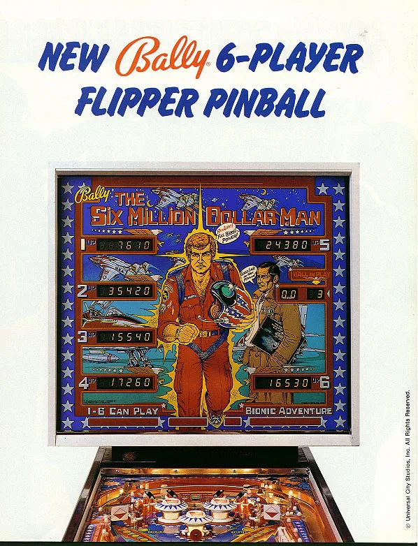
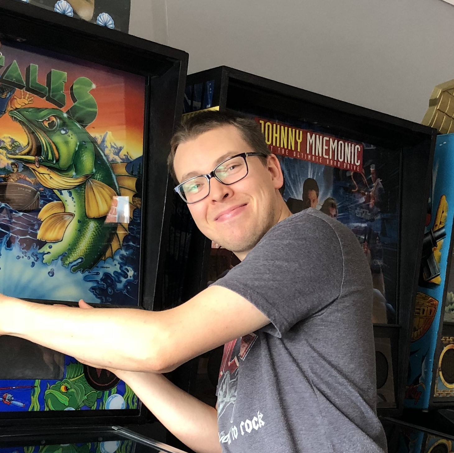
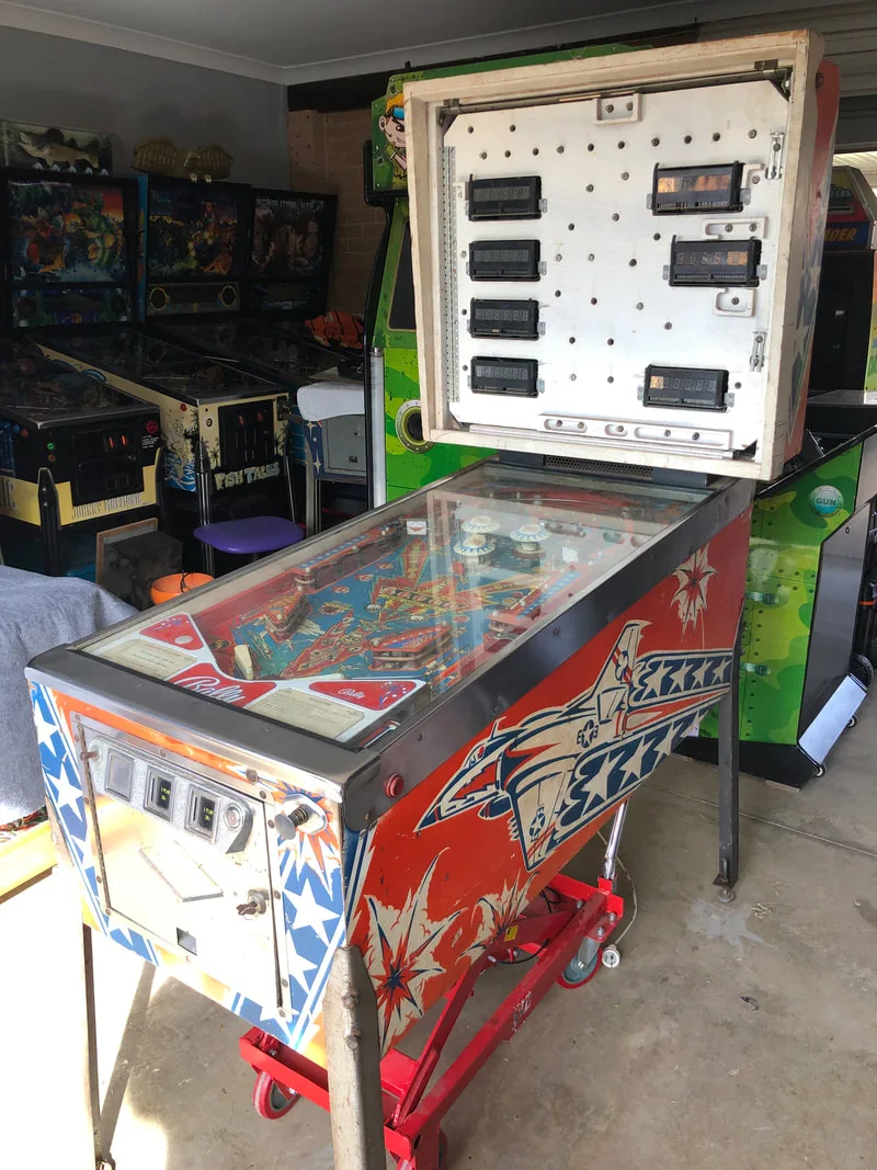
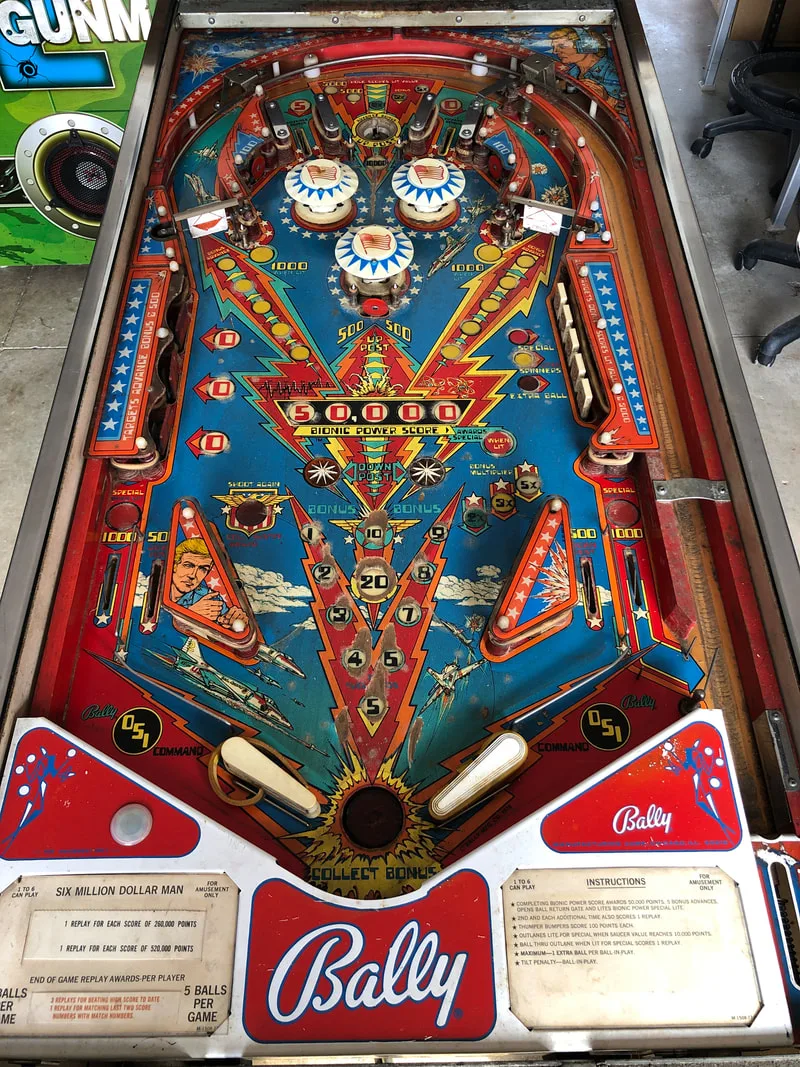
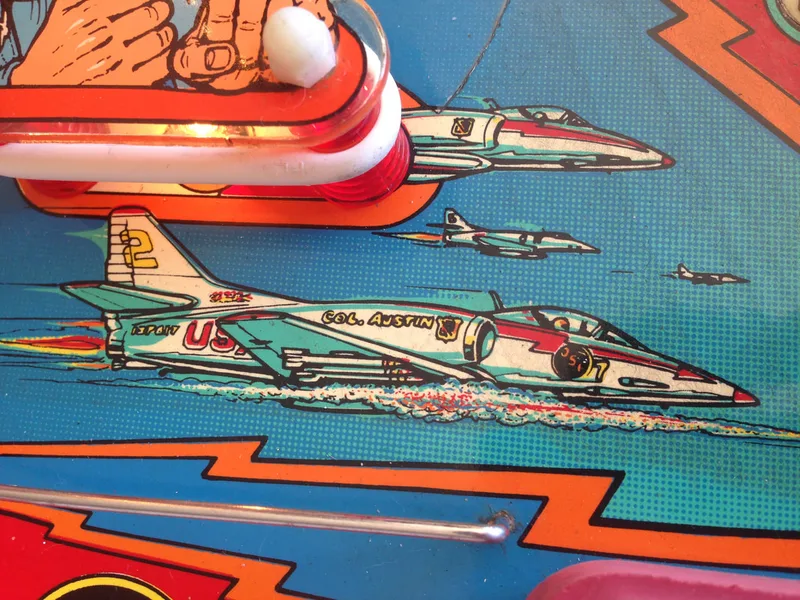
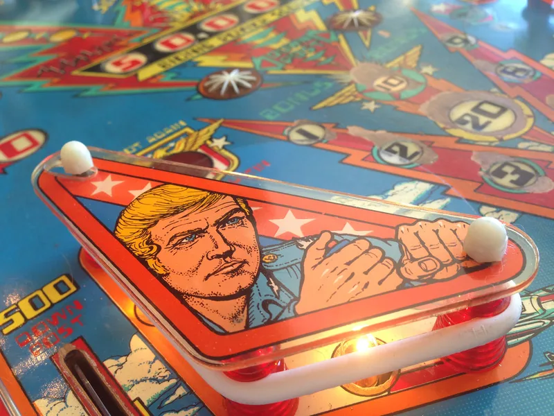
Let's finish off the year by repairing a classic Bally game! But first, I've got to be honest. I've never been much of a fan of late 70s/early 80s Bally games. I generally find the blips and tunes of the early sound boards grating, which makes them hard to play for any length of time. Some say it adds to the nostalgia, but having no nostalgic connection to these games, I can safely say I prefer the sounds of traditional chimes or modern digital stereo. That said, Bally games are classics in terms of gameplay and artwork, so it was a pleasure to get to work on this one for a customer: Six Million Dollar Man (Bally, 1978). This machine had not been working ever since the customer got it from a relative, and they wanted it up and running for their 60th birthday party in a few weeks. We were on a deadline, and there was lots to do!
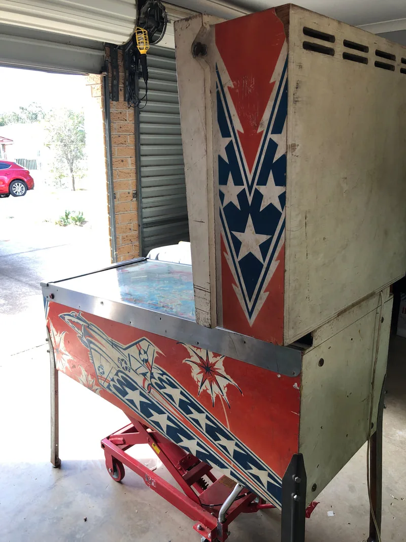
- Timber in good condition.
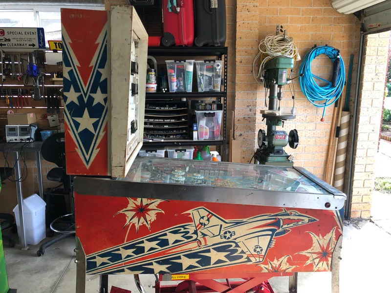
- Side artwork in good condition.
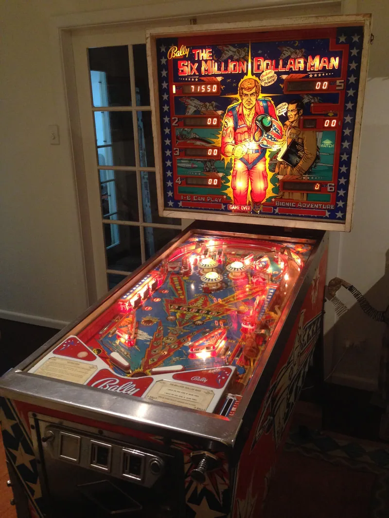
- Backglass in good condition.
- Legs in average condition.
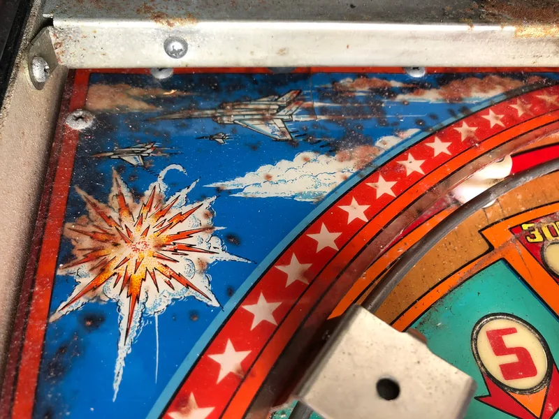
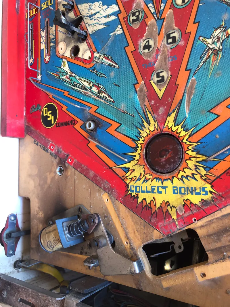
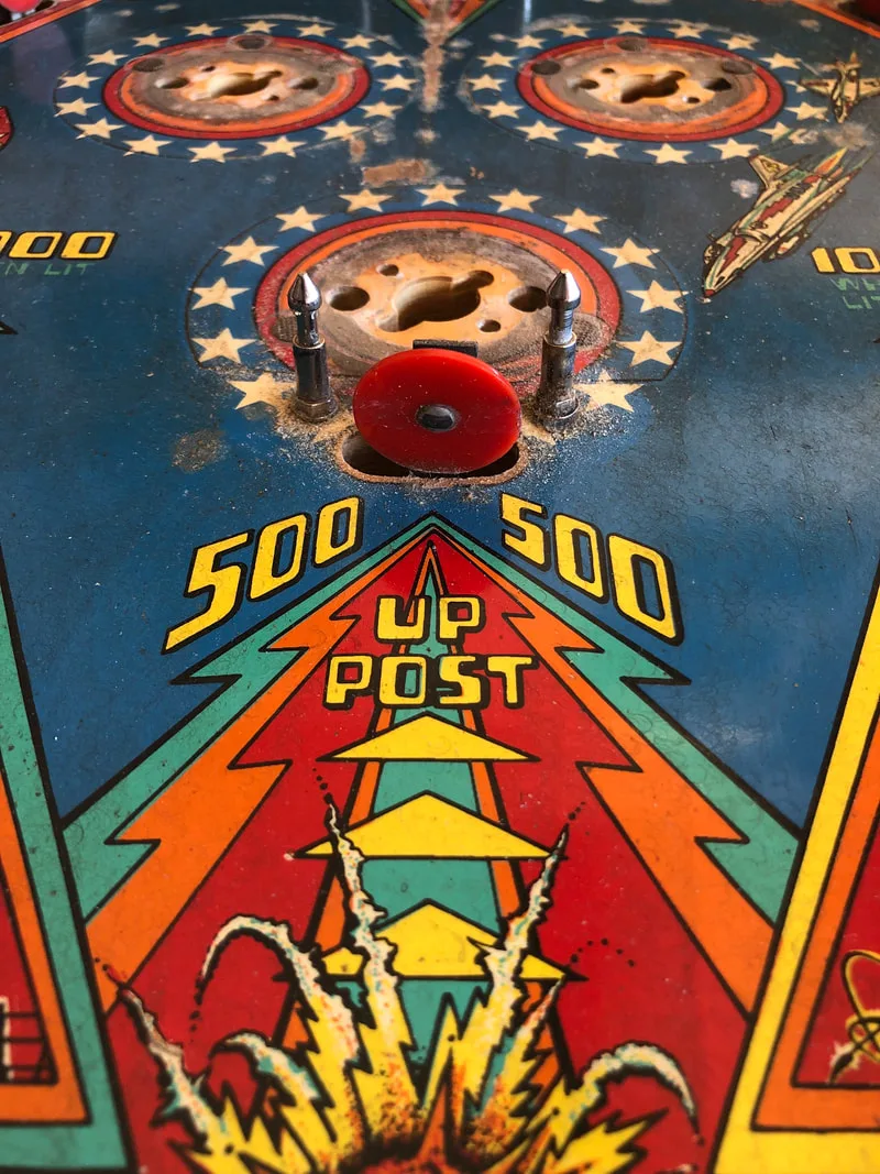
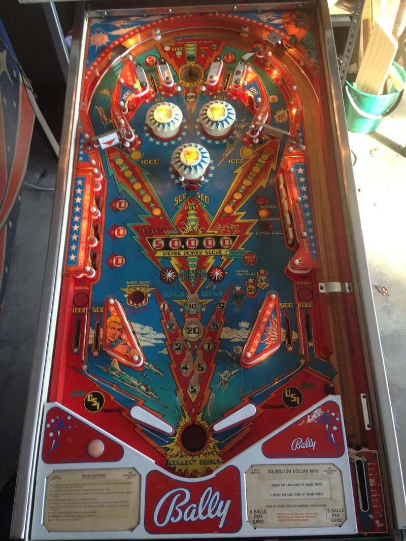
- Playfield was very dirty.
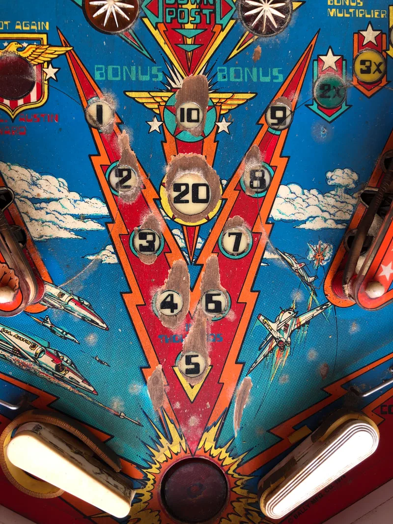
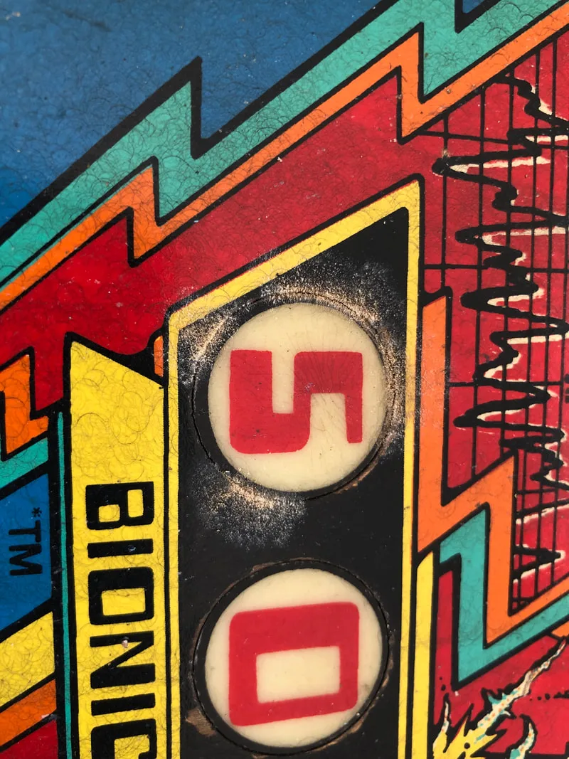
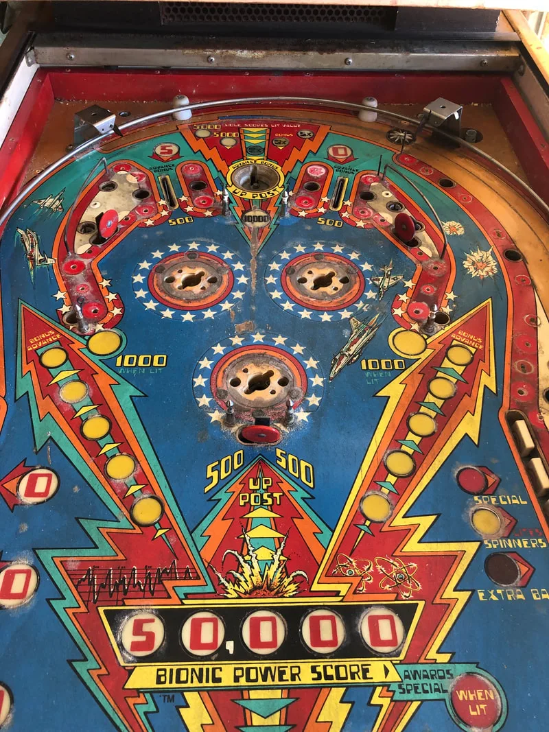
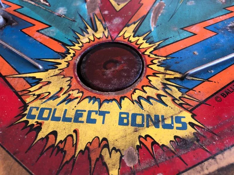
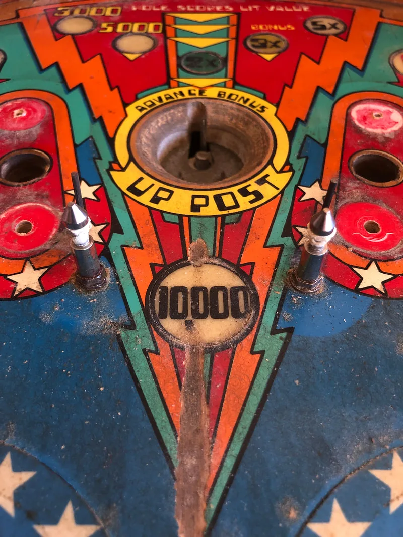
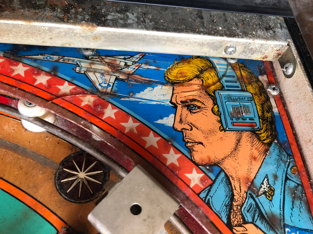
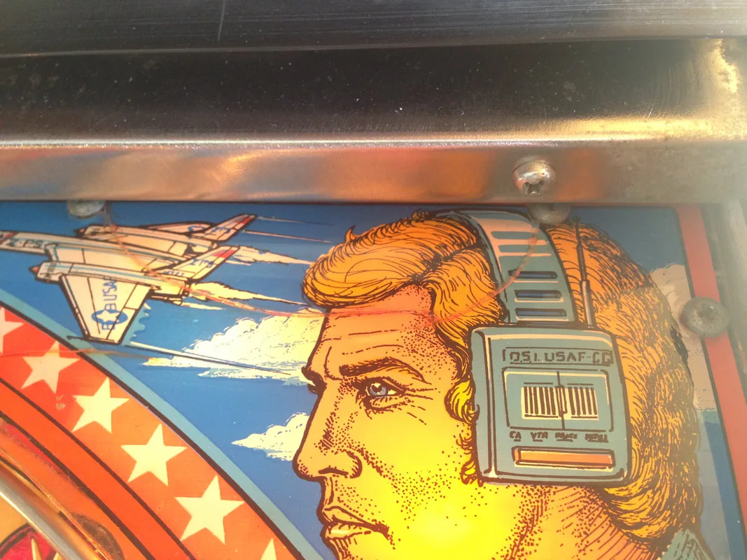
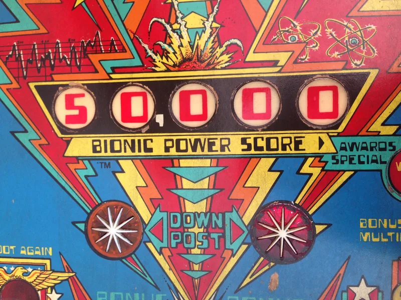
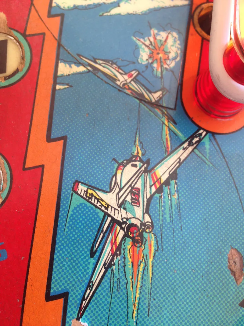
- Playfield artwork in centre was heavily damaged.
- Consumables (rubbers and lamps) in poor condition.
- Plastics in average condition; some broken.
- Playfield mechanisms/toys in poor condition.
- All mechanisms and assemblies in average condition.
- Consumables (coil sleeves, flipper parts) dirty and in poor condition. One flipper coil broken.
- Machine did not boot up.
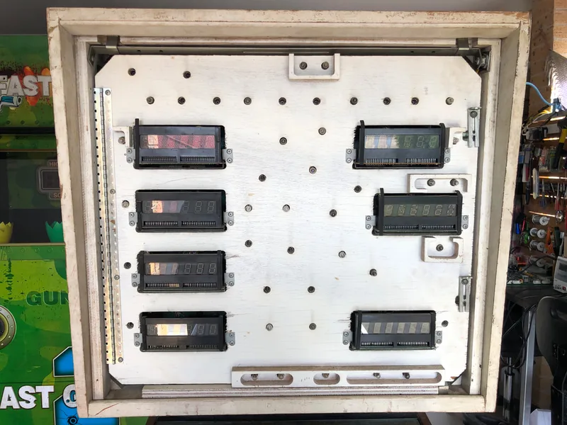
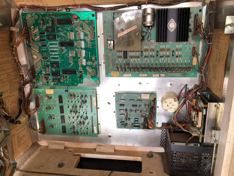
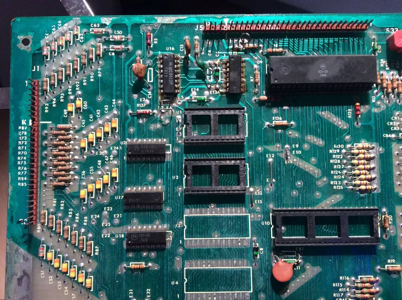
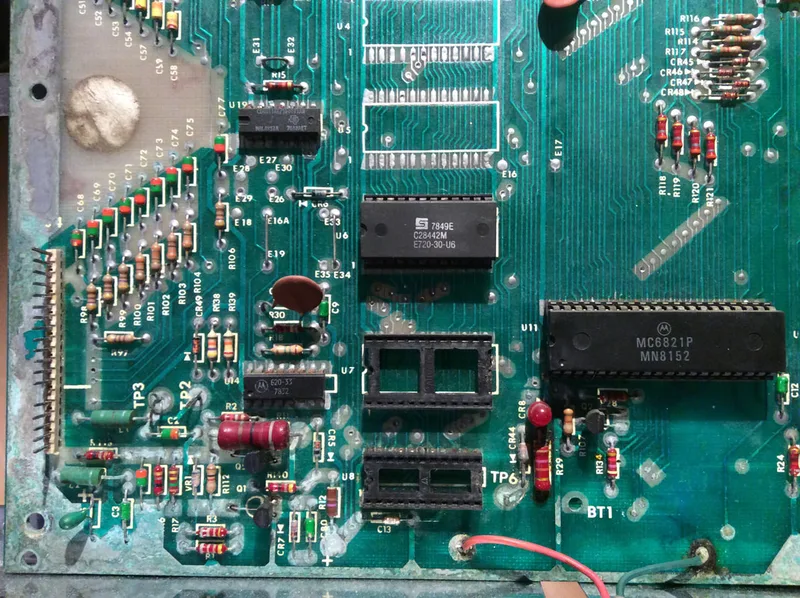
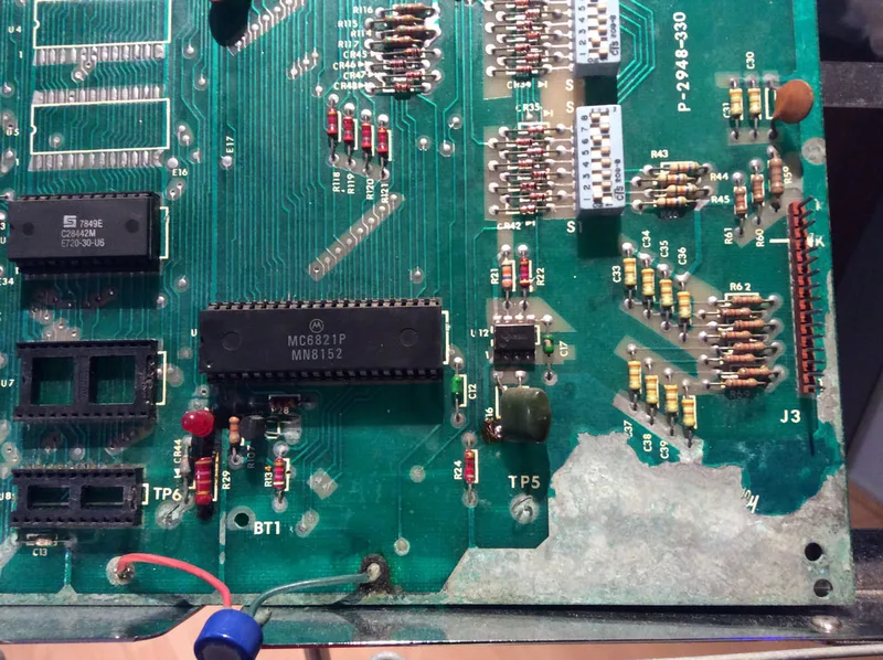
- Backbox circuit boards in poor condition; MPU heavily damaged by battery corrosion.
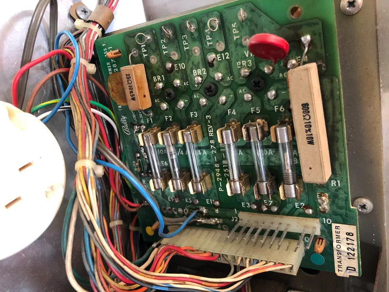
- Line filter varistor blown.
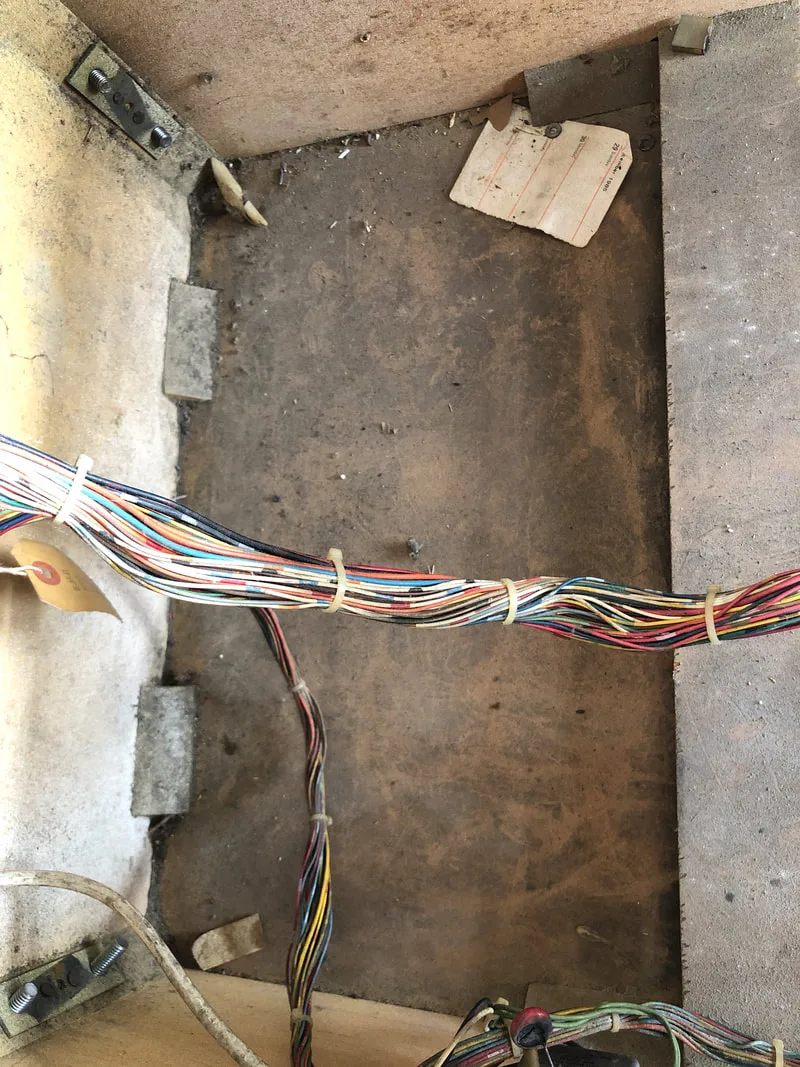
- Cabinet wiring in average condition.
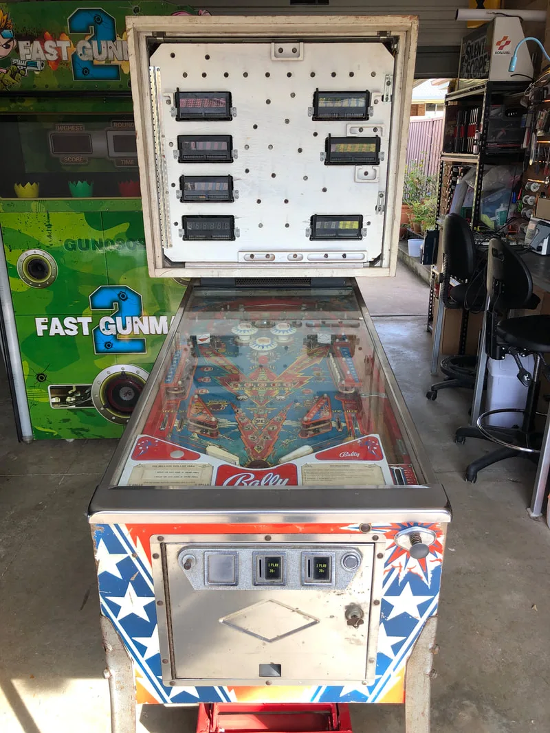
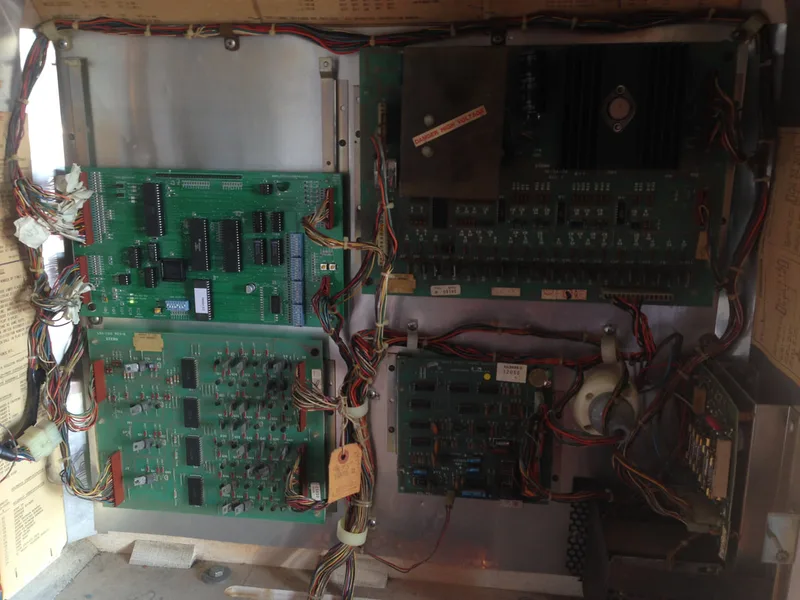
This game had been played a lot in its life, with the centre of the playfield around the inserts being heavily worn. That wasn't too much of a concern, however. The bigger issue was that the game would not boot. I did some cursory checks of the wiring, which had a couple of quirks, but otherwise seemed OK. The voltages on the rectifier board were even within spec (bonus!). However, the MPU board was dead in the water. No LED flashes, no sounds; nothing. I could see that it was heavily corroded by battery electrolyte, which covered most of the board. There would be a fair bit of work involved right off the bat in order to get the game booting and playing at all.
Disassembly
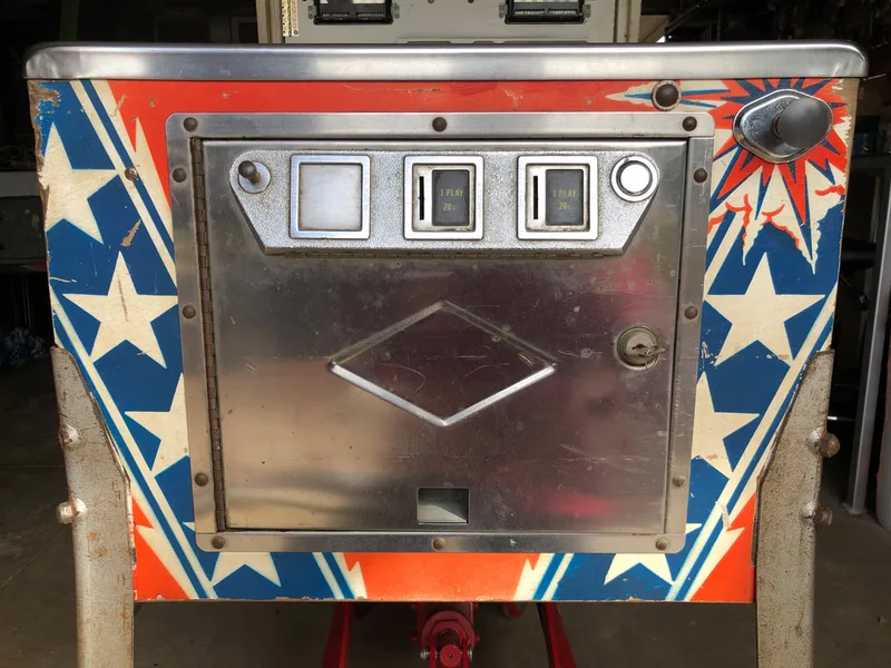
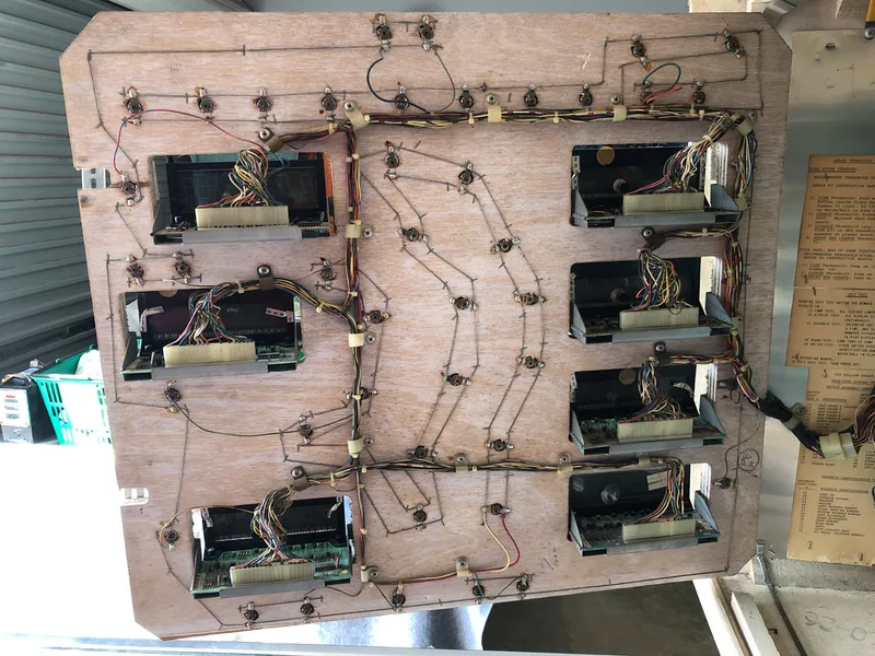
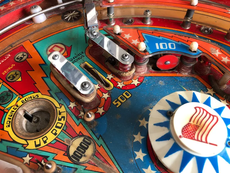
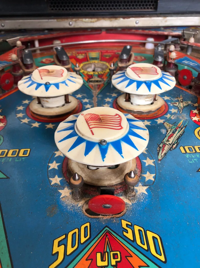
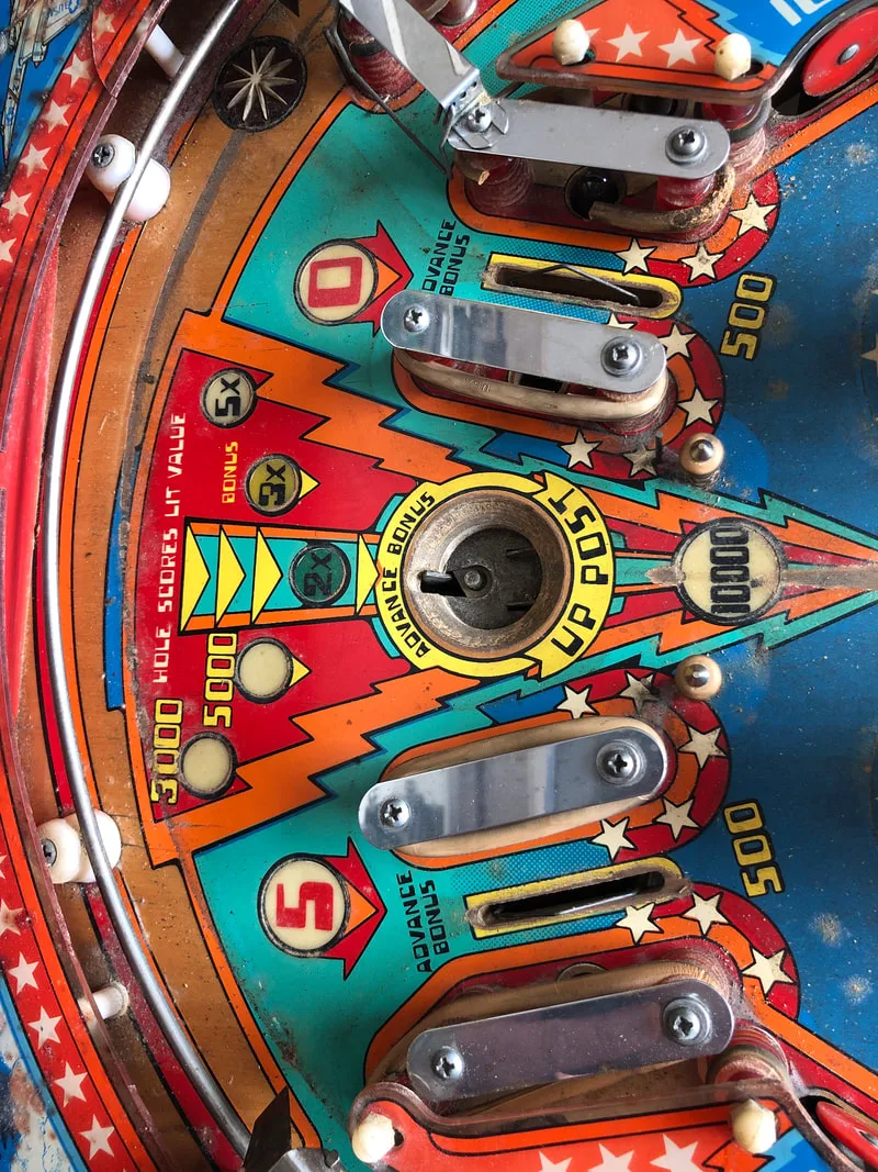
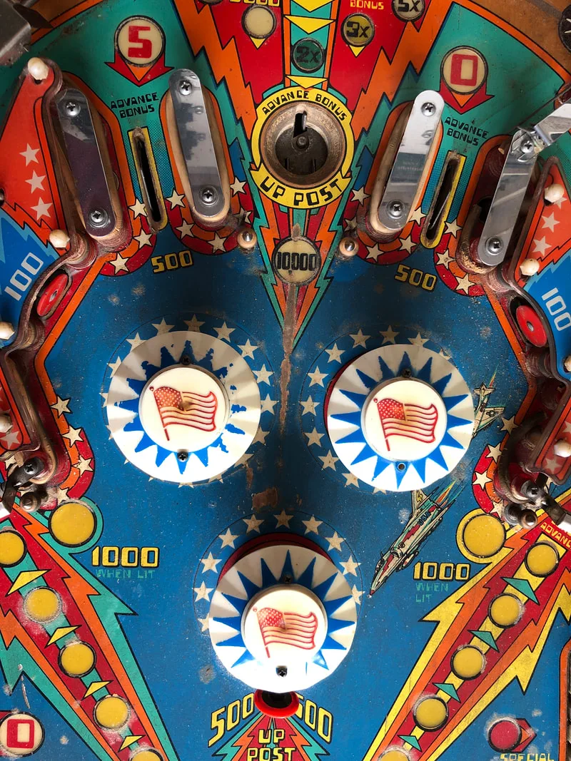
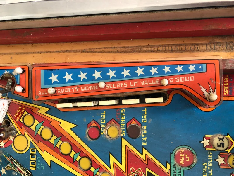
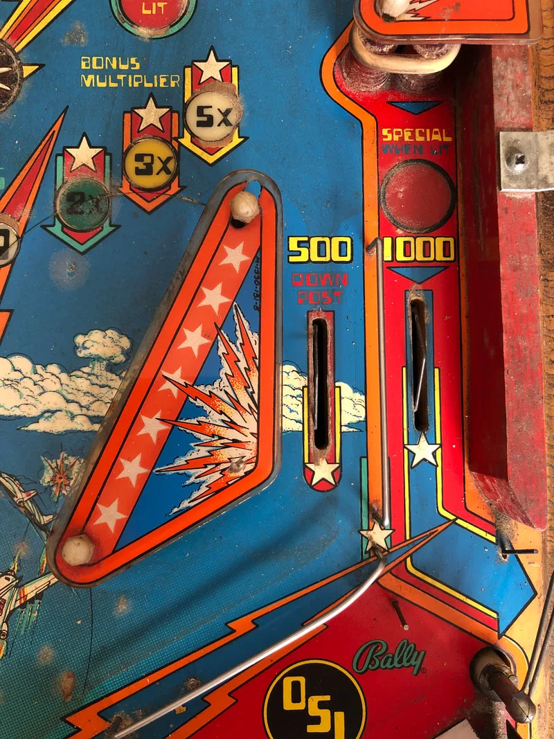
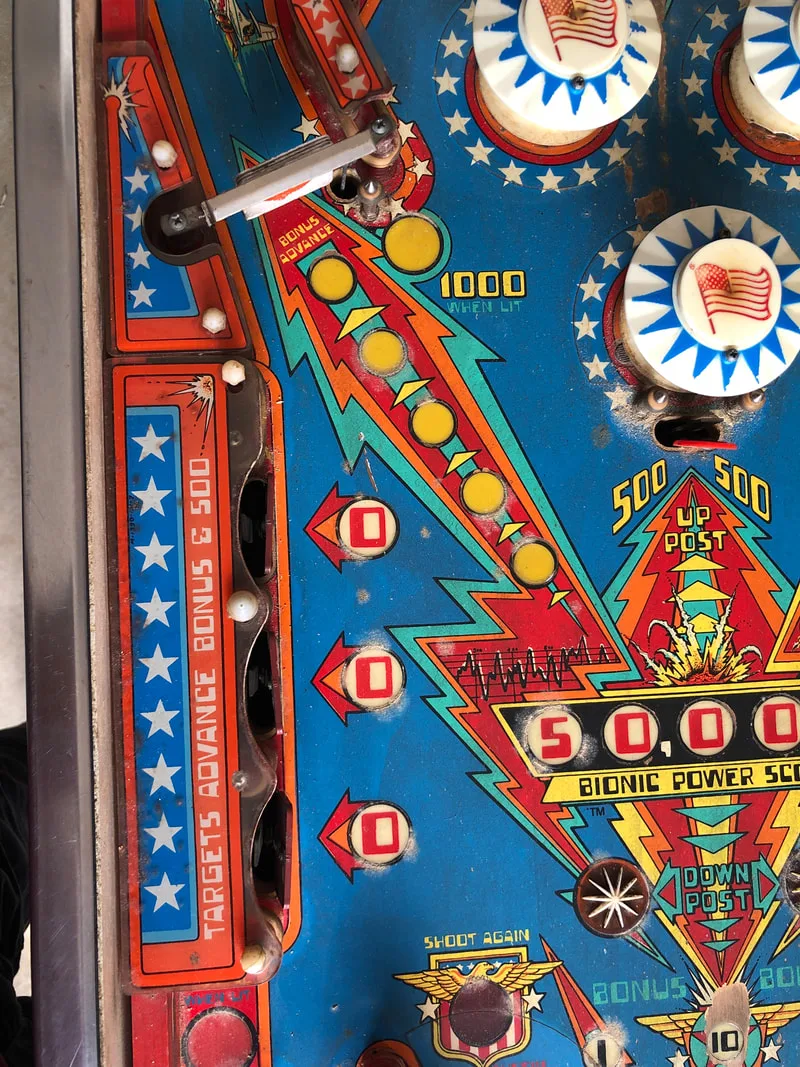
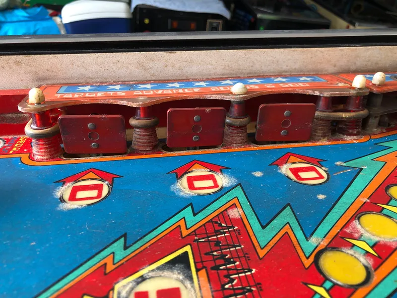
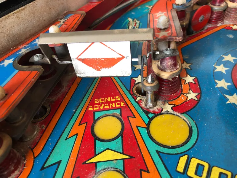
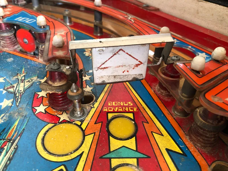
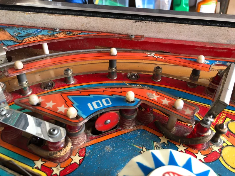
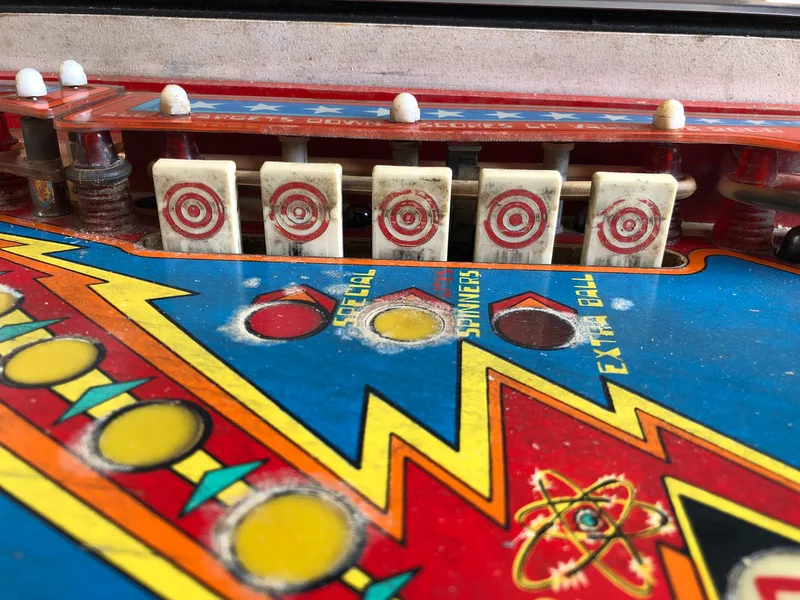
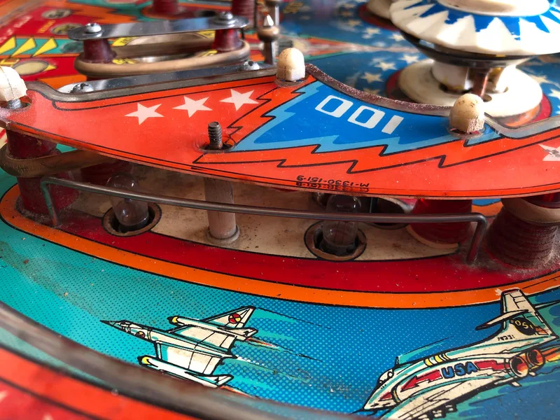
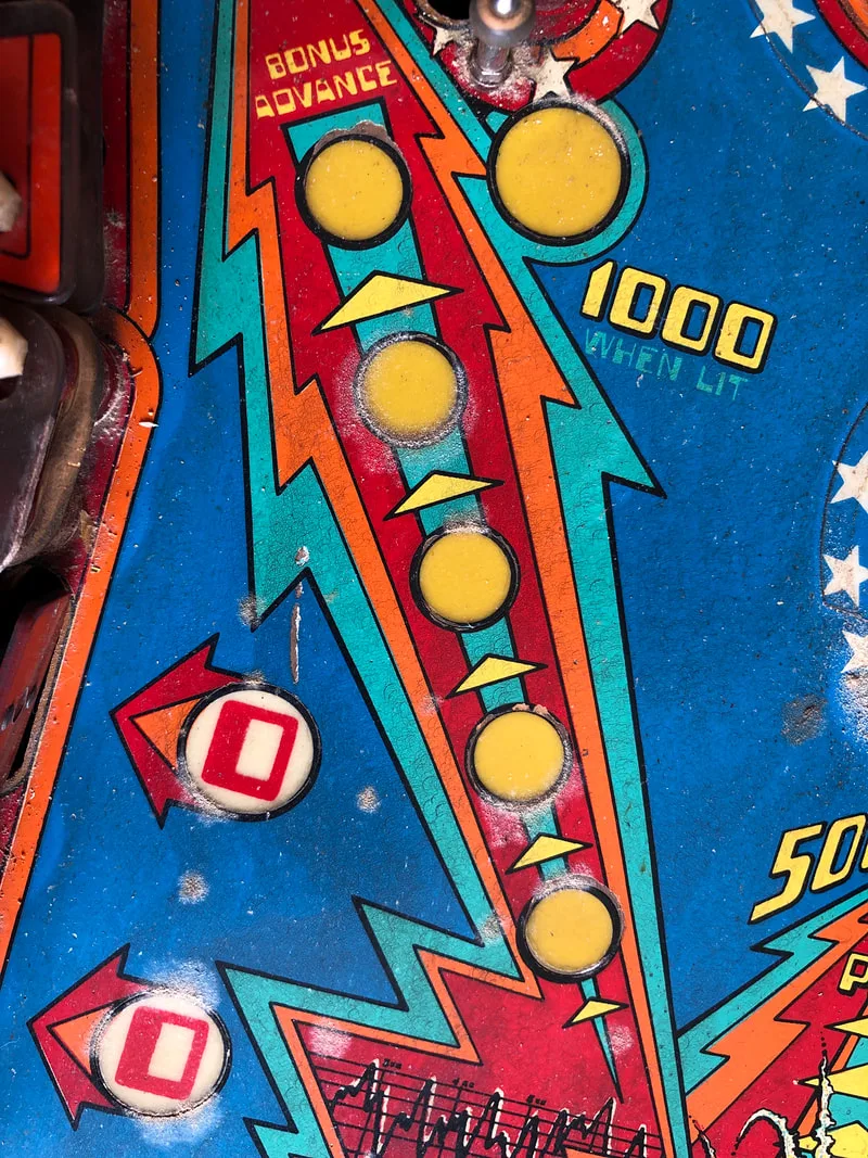
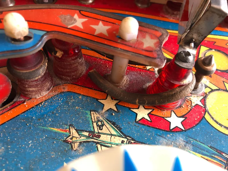
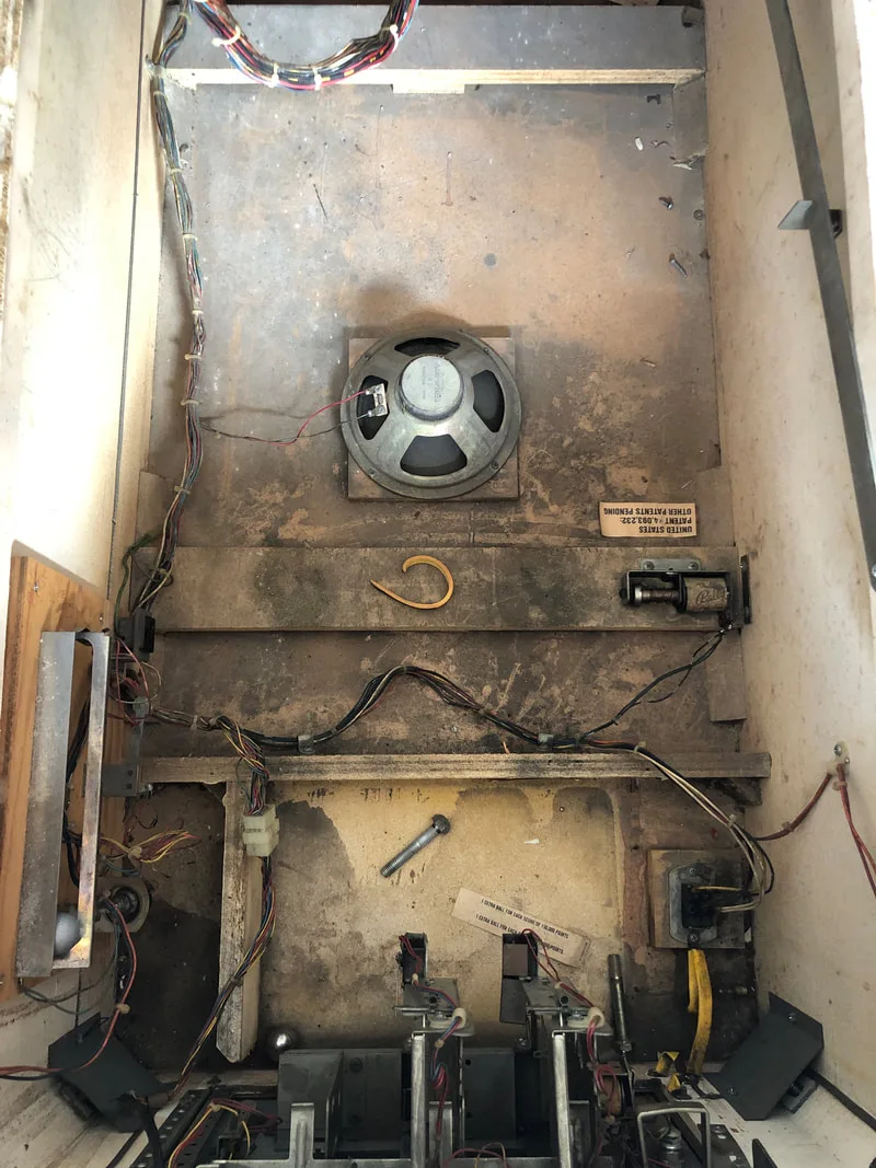
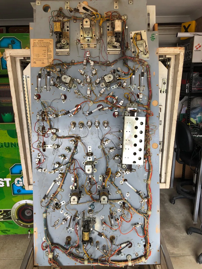
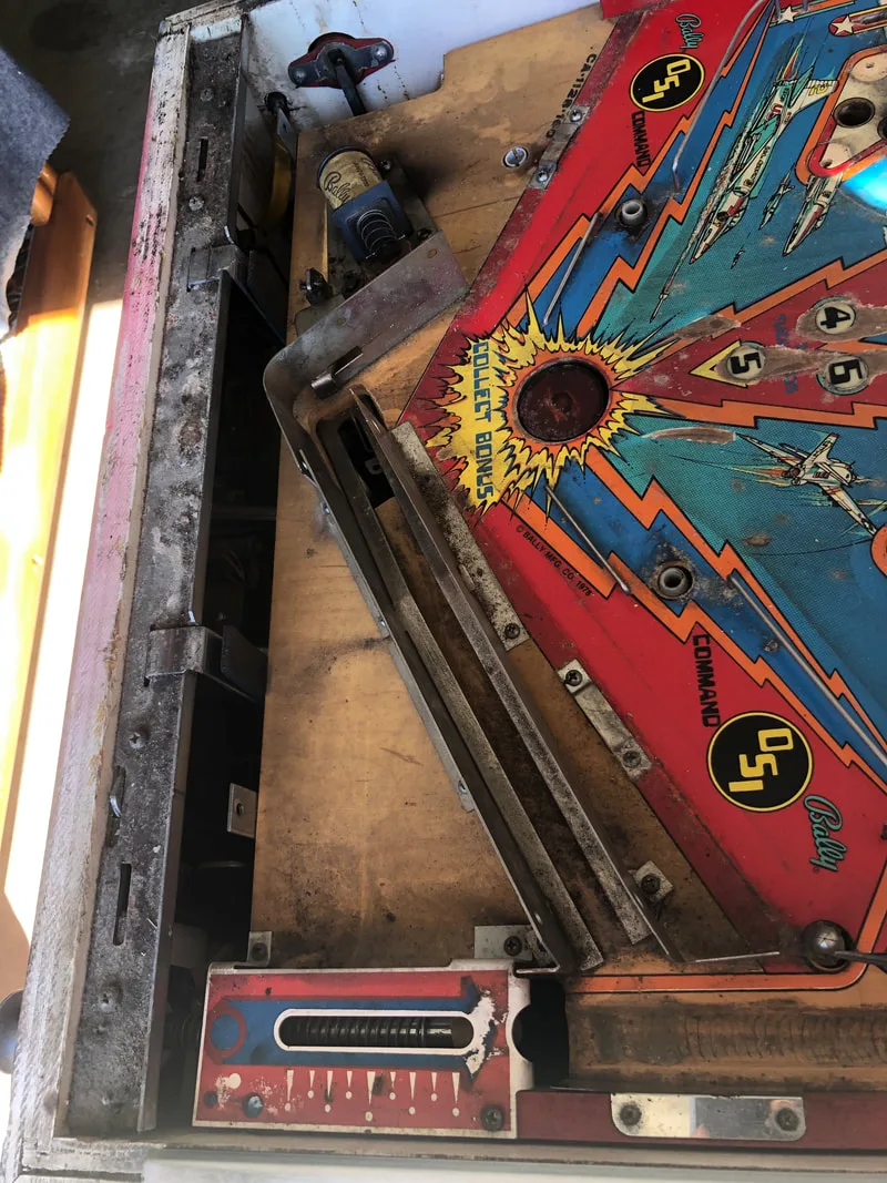
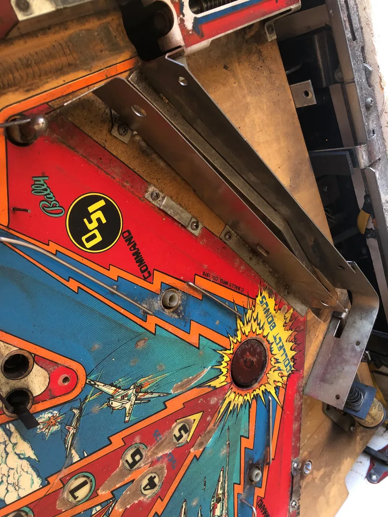
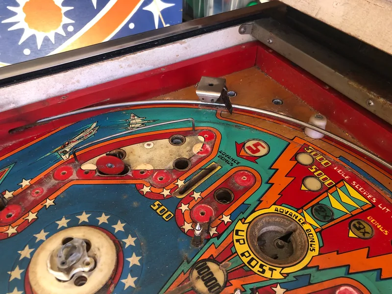
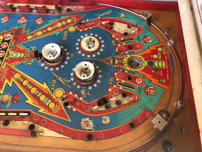
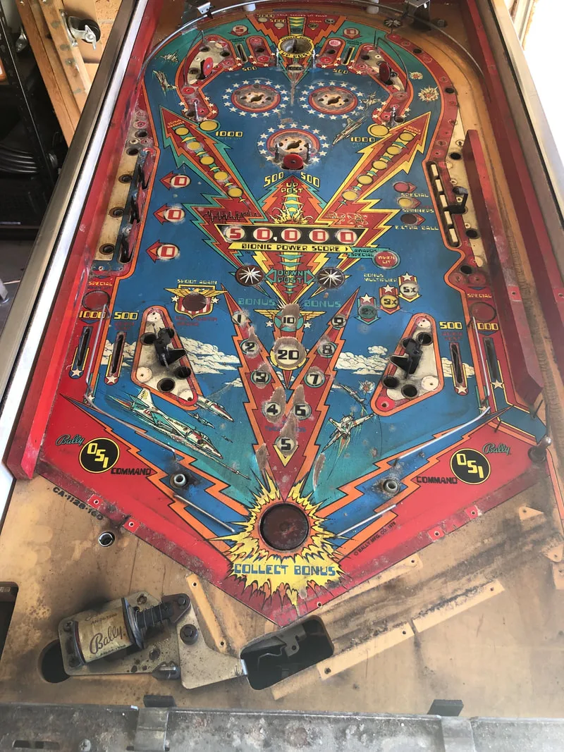
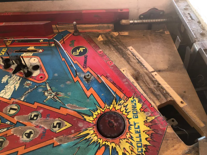
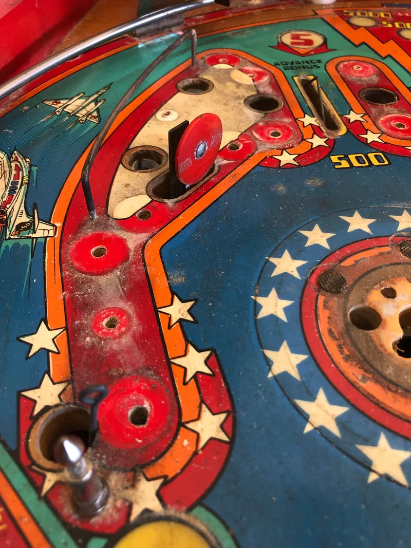
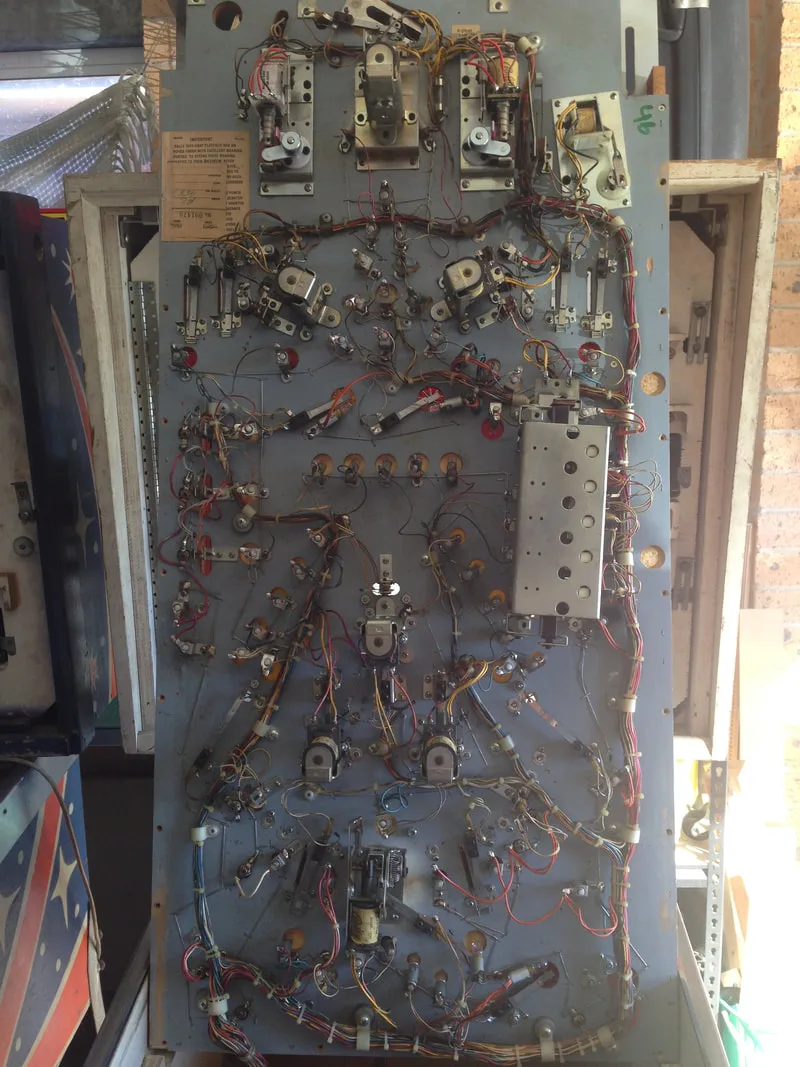
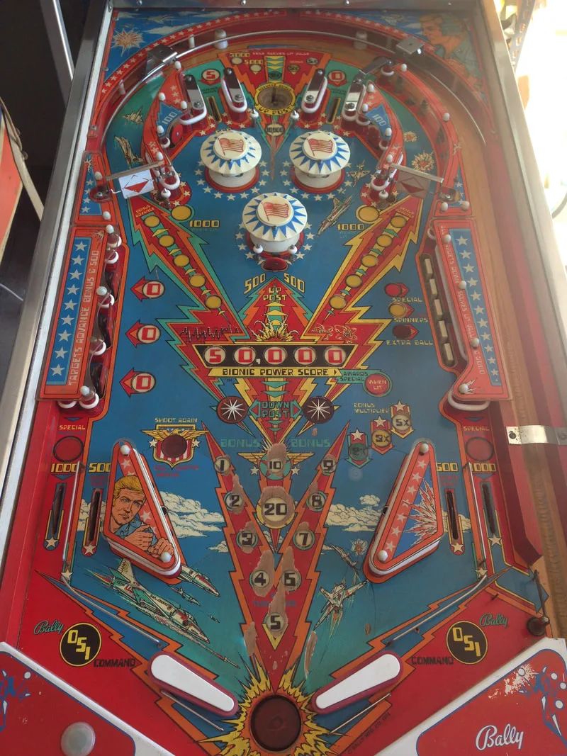
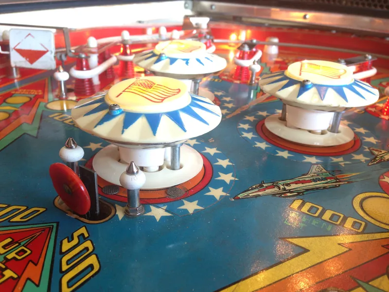
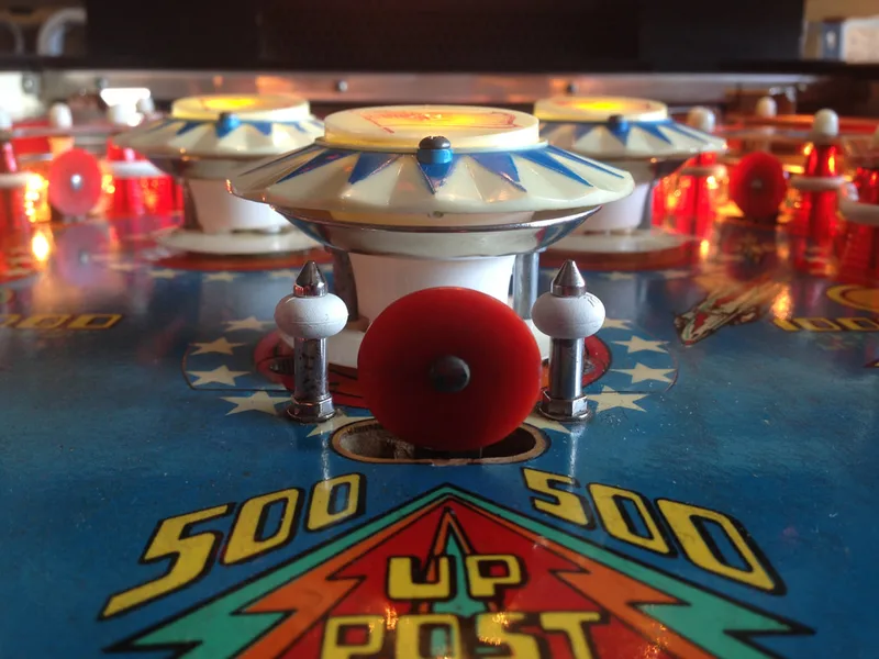
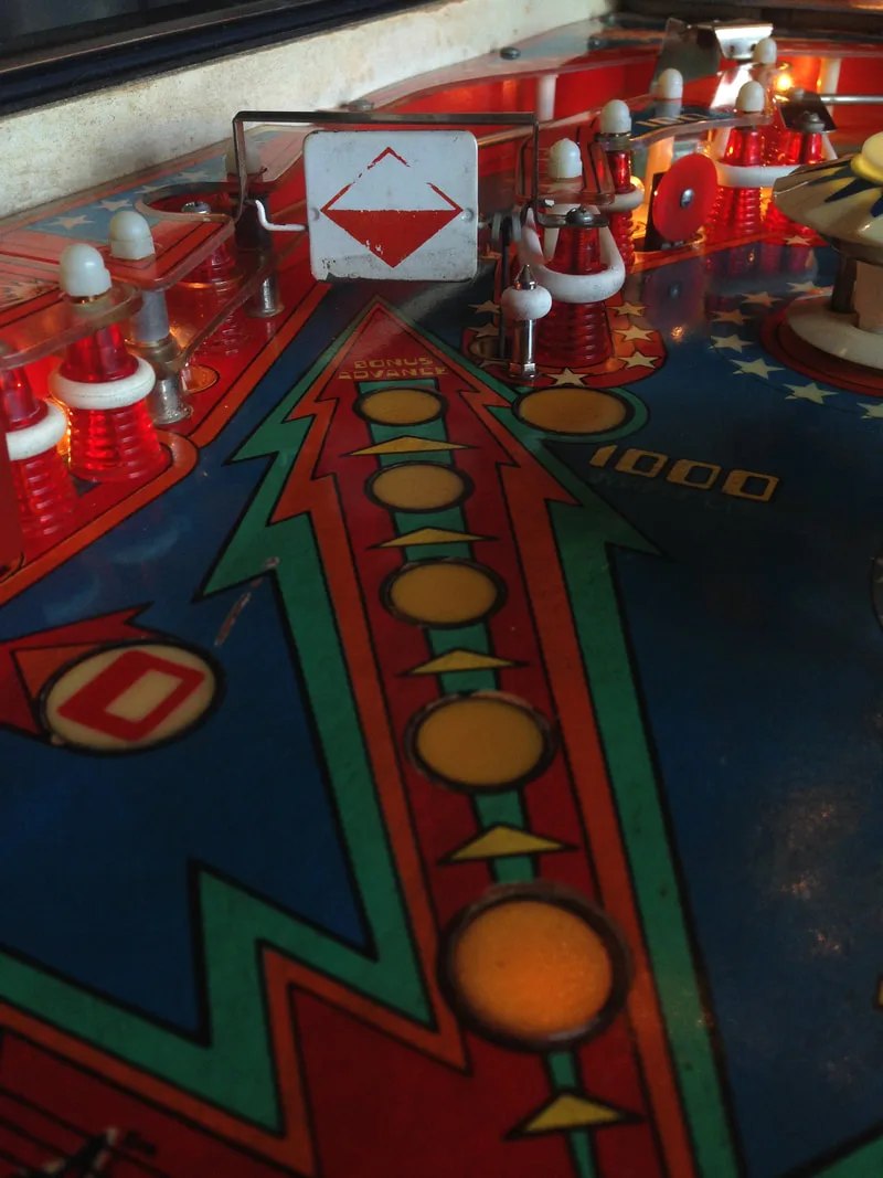
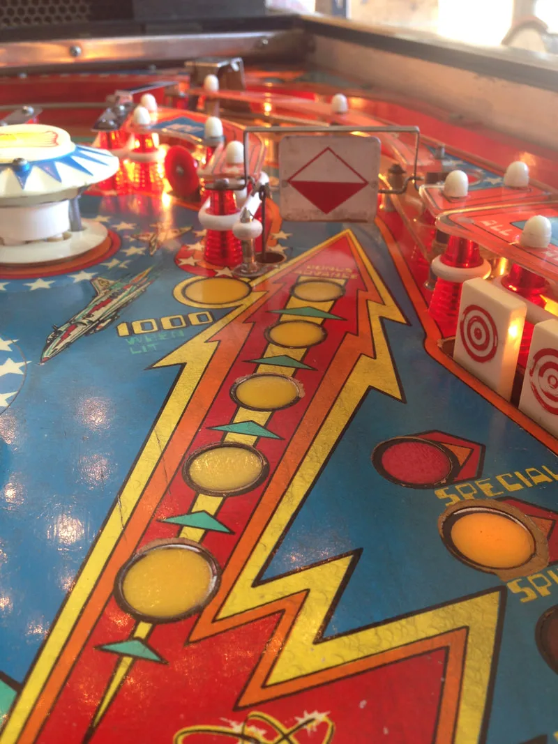
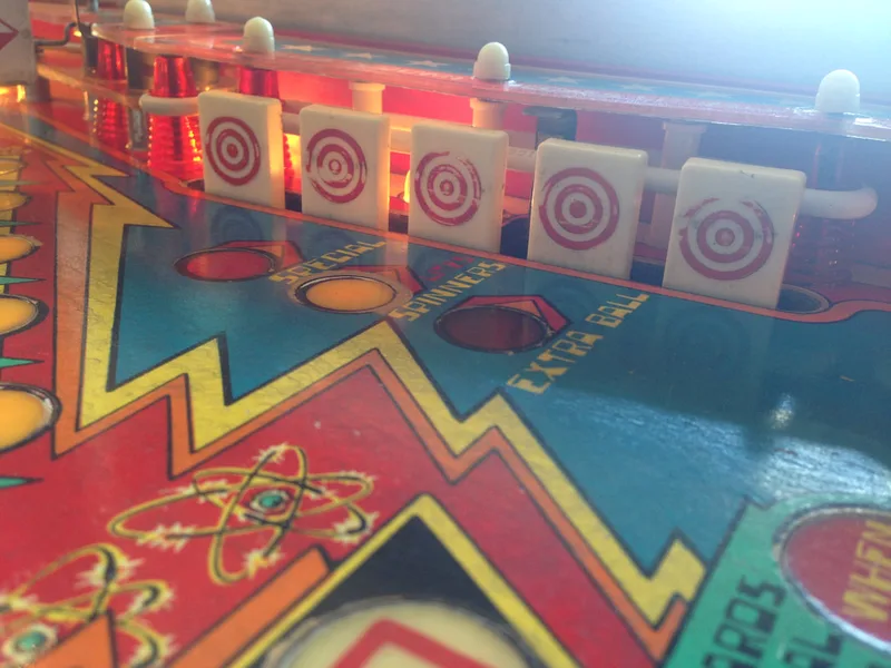
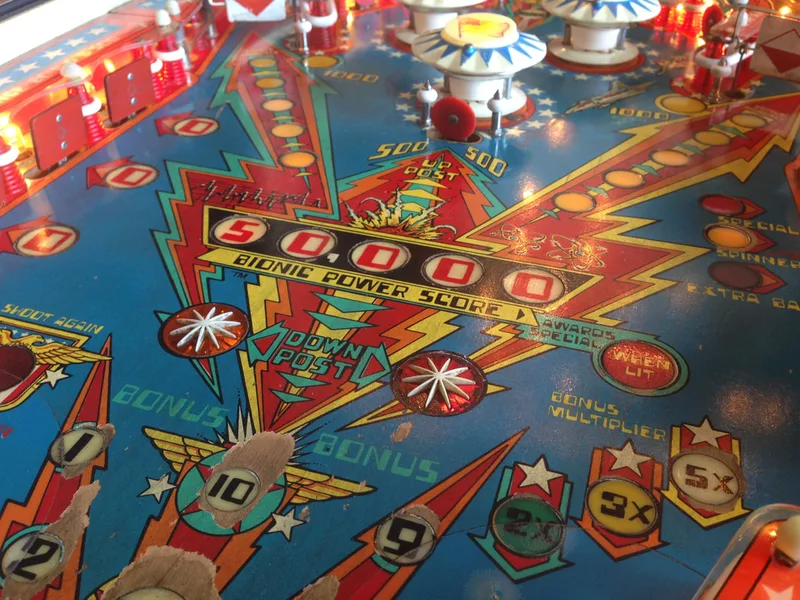
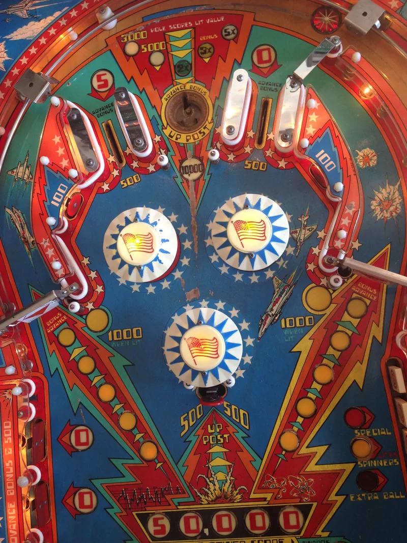
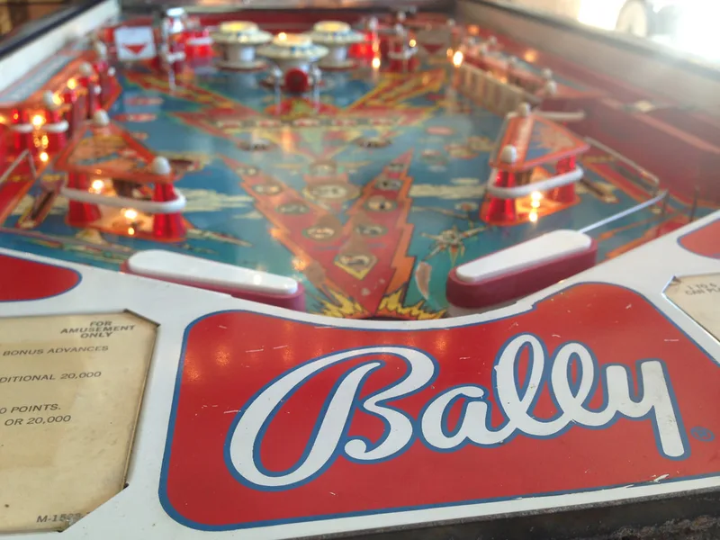
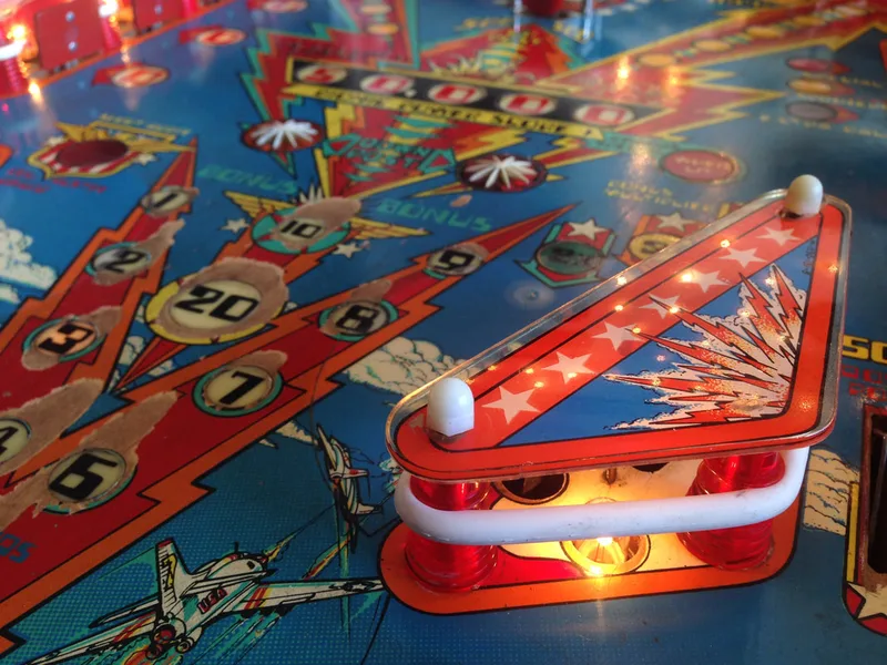
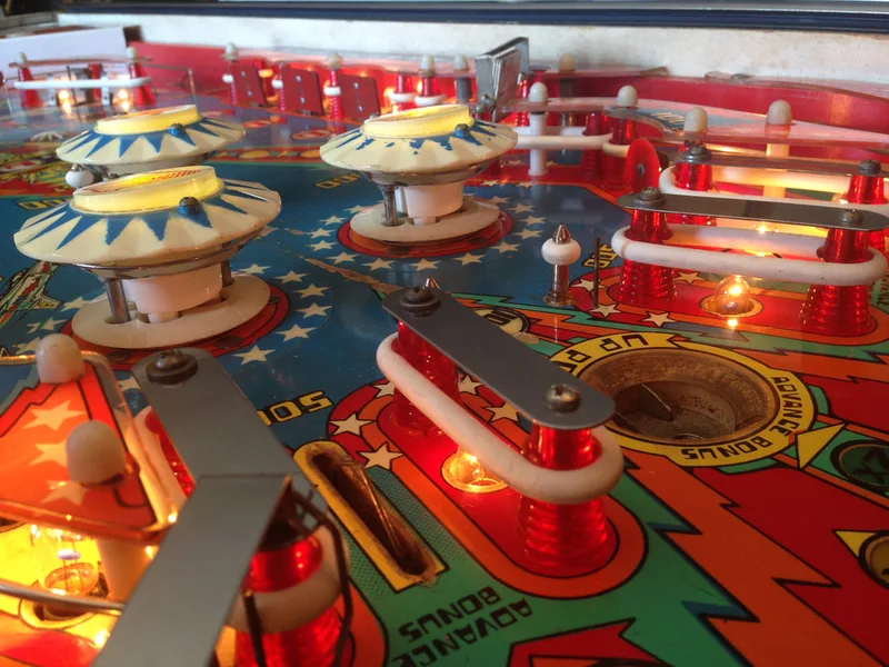
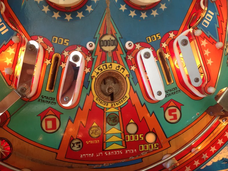
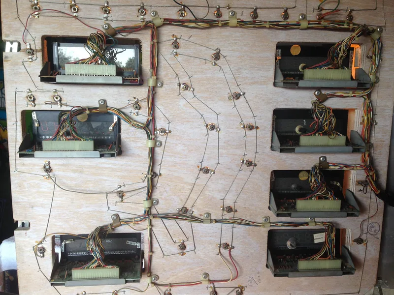
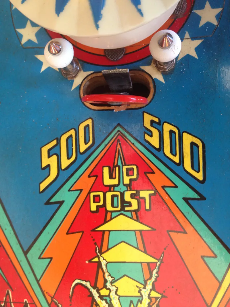
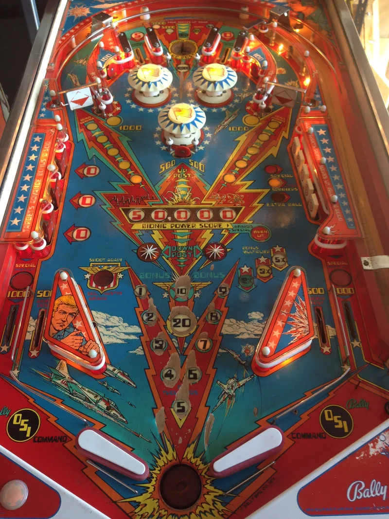
Notwithstanding the fact that the game would not boot, I plowed ahead with playfield disassembly and other repairs while the owner decided on how to deal with the MPU. Classic Bally and Stern games have simple playfields and Six Million Dollar Man was no exception. It has a layout typical of this era: two flippers, two spinners, three pop bumpers and an eject saucer at the top of the playfield. Oh, and some drop targets as well. That's it. Playfield assemblies and parts and wired and put together in the same way on most of these games so once you've taken apart a few, you start to learn where everything goes and how it fits together. But, as always, take lots of pictures if you're not sure! The photos below show the initial condition of the game and the process of disassembly.


After disassembly, the game went through my standard restoration process to get it playing and looking like new. During the restoration process, I dealt with a number of issues, described below.
Tips & Troubleshooting (click on sections below to view details)
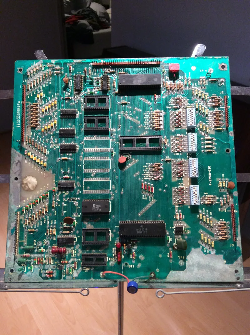
So, there were a couple of options to deal with this. The original board could be repaired, or a new board could be purchased instead. I left this decision with the owner. The reality of this board was that it would have taken many hours to repair. Plus, it had been worked on in the past, meaning that prior work potentially needed to be re-examined. The owner decided to go for a brand new board instead, which ended up being about twice the estimated price of repairing the old board. Given the scale of damage to the old board, I think getting a new one was the better choice. The owner sent me a new Alltek Systems Ultimate MPU board, which I could install in the game. These boards are available locally (PSPA), as well as replacement solenoid driver and lamp driver boards for Bally games. But before I could install the new MPU, there was additional work I had to do.
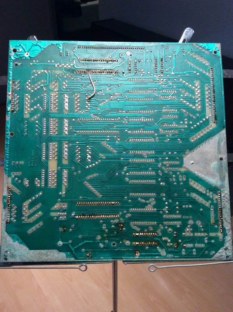
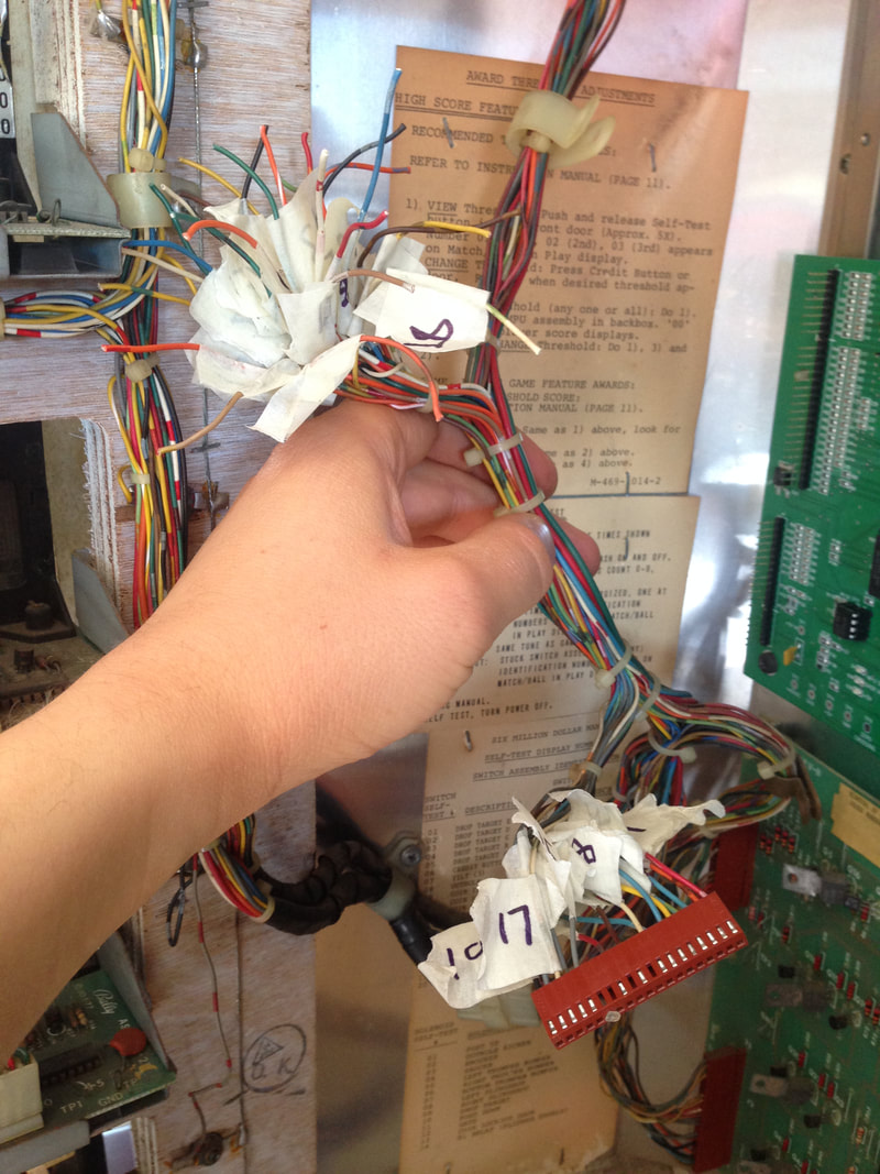
As the battery corrosion had engulfed the perimeter of the old board, some of it may have affected the crimp terminals and connectors on the left side of the board. So, the wires had to be trimmed so there were no traces of electrolyte left, and the crimp terminals had to be replaced. This is a long process, so set aside a few hours to get it done properly!
I extracted the terminals from the connector housings with a pick and labelled them just in case the manual was wrong (never rely on the manual!). I wanted to reuse the connector housings, so these got to soak in vinegar overnight before being rinsed thoroughly with water, then being left to dry in the sun.
To see how far the corrosion has advanced into a wiring loom, strip a few wires from the connector and see whether you can notice any green residues which are evidence of the dried up electrolyte material. They will look like green crystals rather than a goopy, green slime. Don't freak out too much if you see some green, slimy material as this is the plasticiser leaking from the wire insulation. Pinwiki has a good description and photos of this phenomenon. Either way, if you see anything green, you'll need to trim the wire back until there isn't any. Luckily I didn't see any evidence of corrosion advancing into the wiring loom, so I just cut a couple of centimetres off each wire and stripped them back for recrimping.
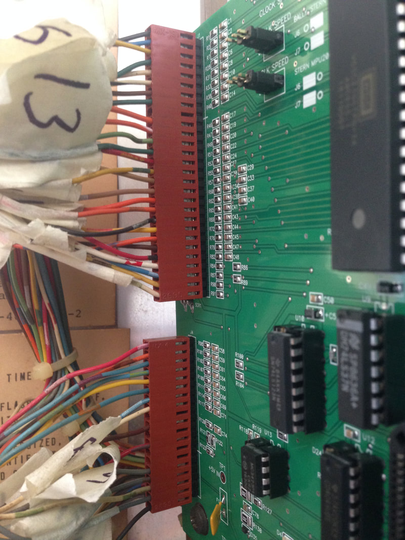
Next was the laborious process of stripping each wire and crimping it onto a new terminal. Normally I baulk at this process because it takes so long and is fiddly. But this was mainly because, up until this point, I had been battling with a pair of decrepit, half-broken crimpers. I bought a new set for cheap (eBay). These SN-28B crimpers might seem like cheap Chinese junk, but they were highly recommended. They did not disappoint! They crimp cleanly and do a nice, two-stage crimp in one go. A couple of crimps required some tightening with pliers, but for the most part, they were good as soon as they were released from the crimper's jaws. Grab a couple of hundred crimp terminals (RS Components). If you're doing all of the connectors in the game, you'll get through at least a hundred.

Labelling and removing wires from connector housings.

New terminals crimped and installed in the original connector housings
Once the new MPU board was installed and the proper game selection switches were adjusted, the game booted and played without issue on the first attempt! While Alltek boards can be expensive, they do save a lot of stuffing around with alkaline leakage repairs.
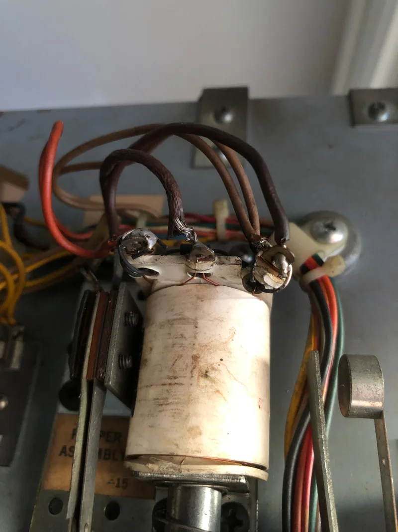
Original coil with damaged plastic bobbin


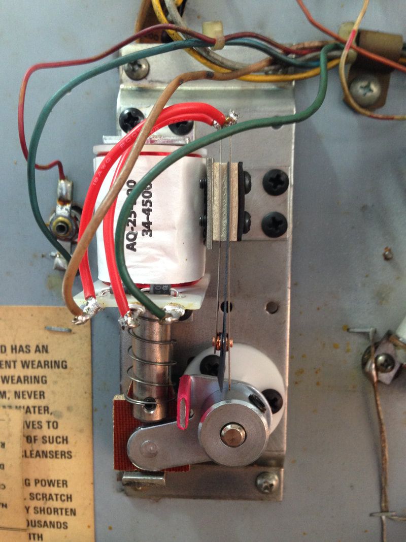
New coil installed with new assembly parts
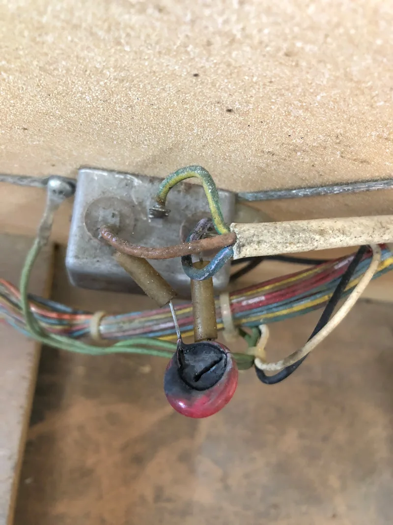
Original destroyed varistor

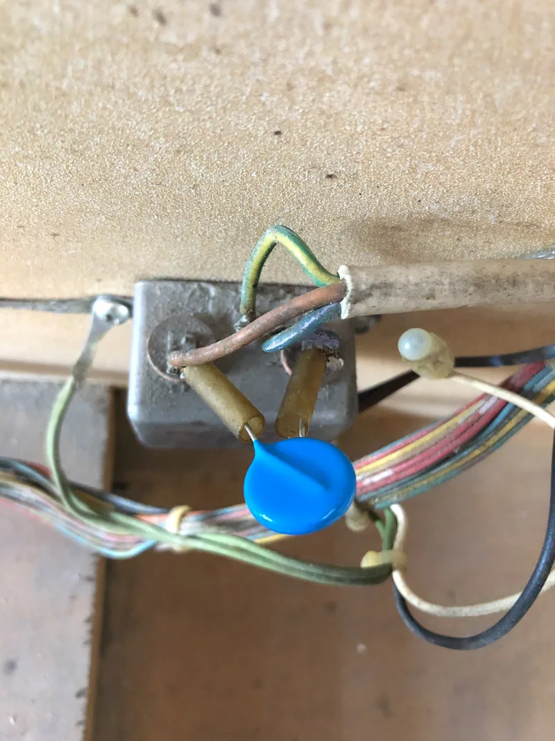
Brand new varistor installed

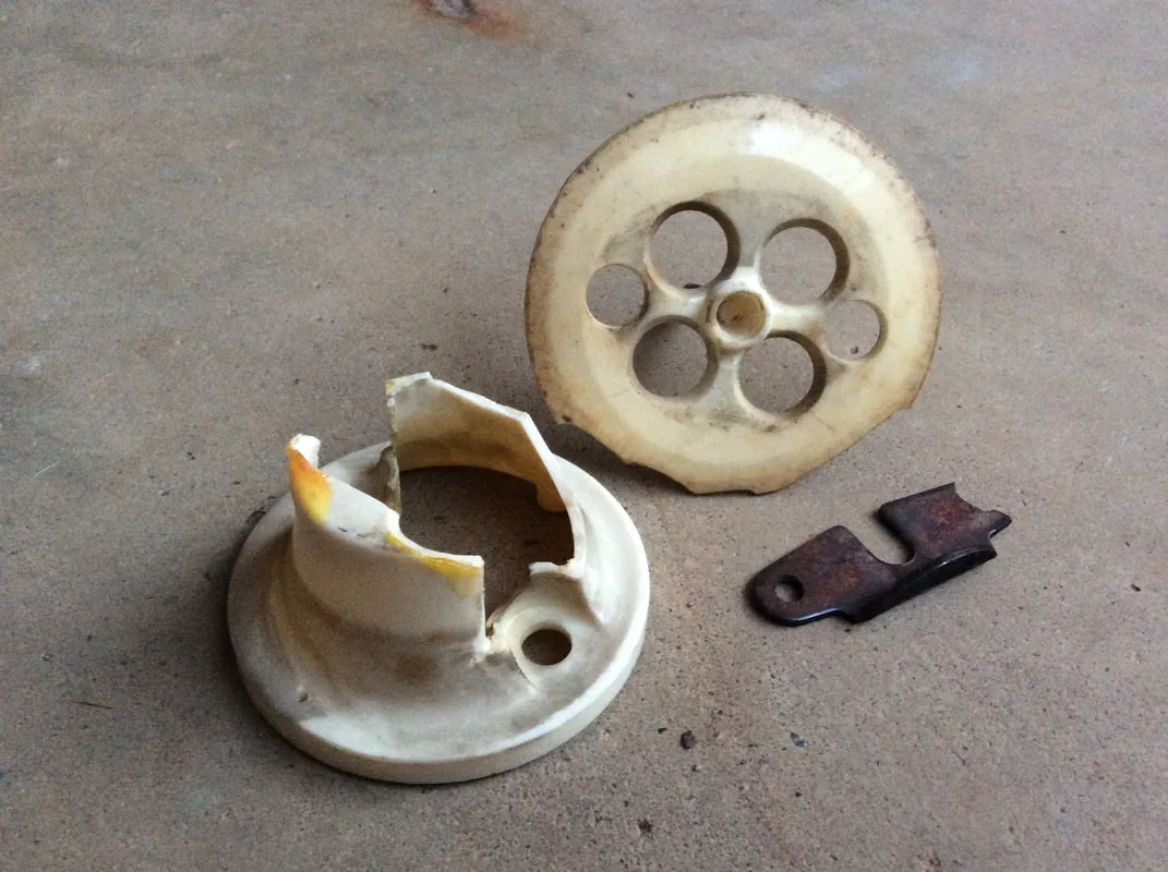
Broken pop bumper body, skirt and yoke


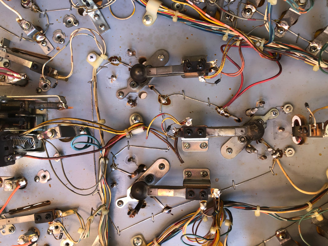
Playfield underside after removal of pop bumper assemblies and coils

Pop bumpers fully rebuilt with new parts


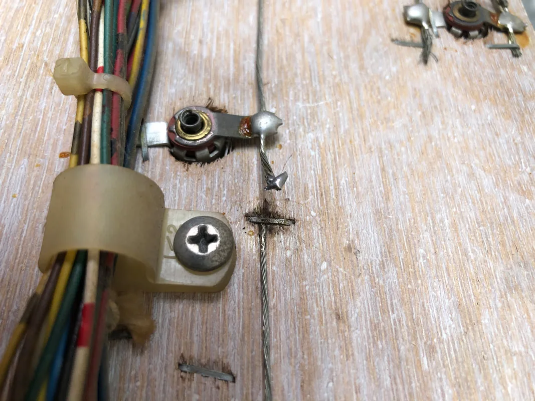
Screw which had fallen into and shorted a lamp socket
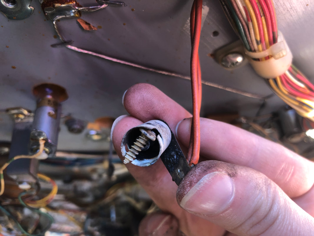

Burn marks on the plastic above the lamp socket
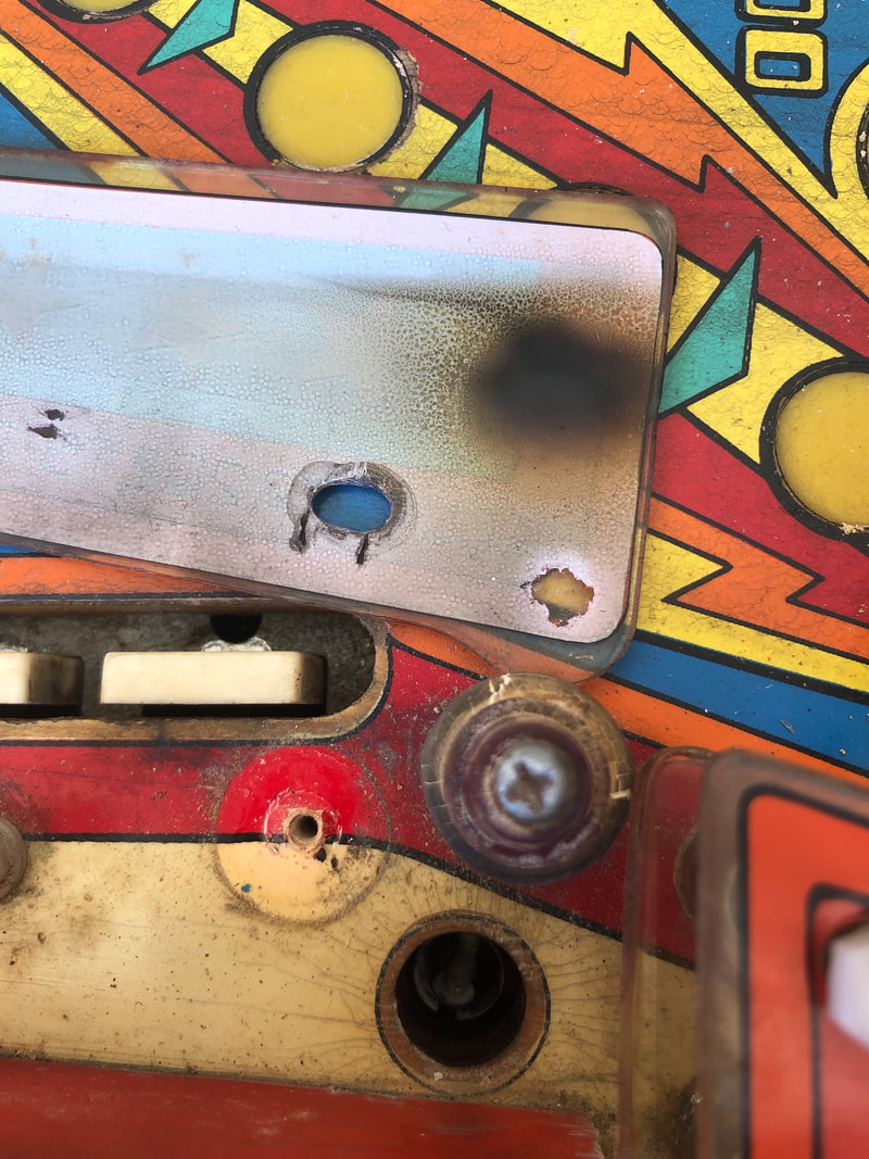
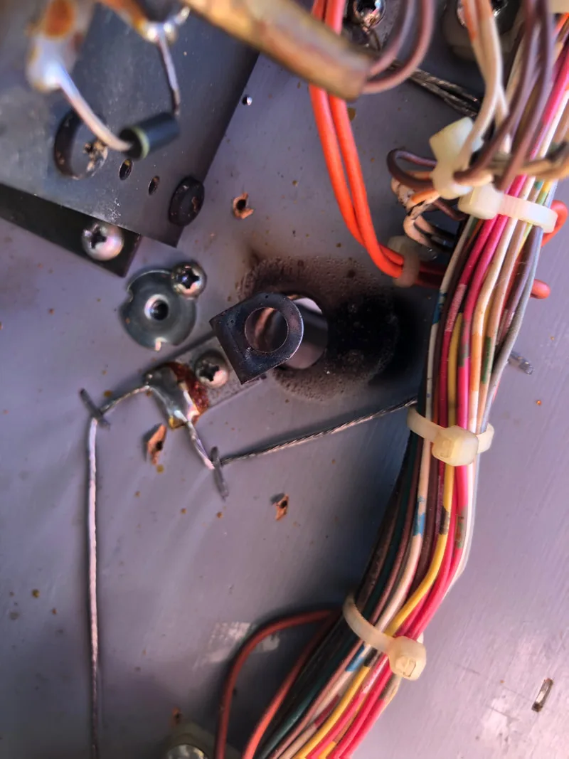
Burn marks underneath the playfield around the socket
I replaced the shooter rod with a slightly longer one, similar in length to the longer Bally shooter rods used around this period (approx. 8.5" total length). Alternatively, if your shooter rod is slightly too short, you can bend the prongs of the metal guide that the ball sits on when it rests in the shooter lane. Bending these backwards will get the ball to sit further down in the shooter lane, giving it better contact with the rod. Some shooter rods of specific lengths are getting hard to procure. Any shooter rod will generally work as long as it still plunges the ball properly.

Original shooter rod which was too short.

Break in backbox lamp wiring.
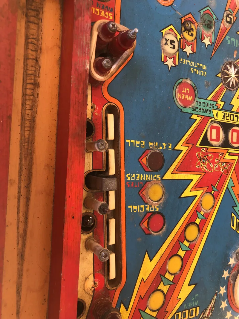
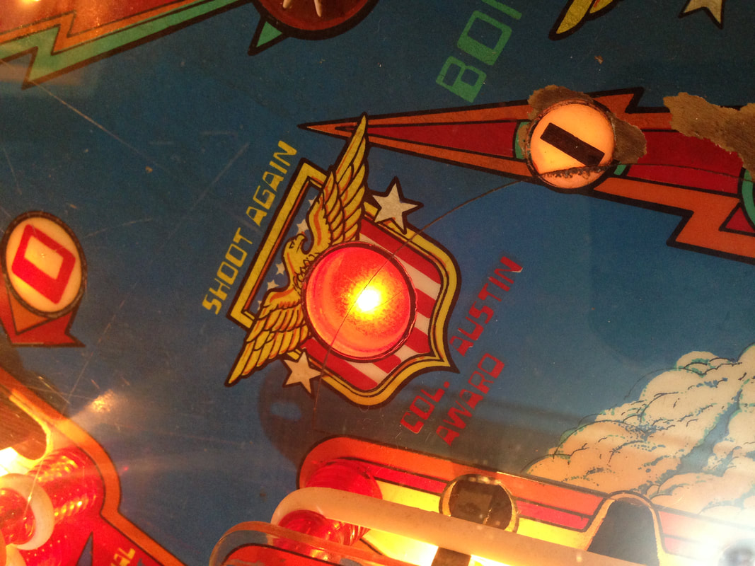
The second lamp issue was related to the shoot again when lit lamp on the playfield. This lamp was locked on, and shone much brighter than a normal lamp. There was too much current going through this lamp for some reason and the only way to get it to turn off was to unplug the connector on the lamp driver board associated with it (J2). This lamp is unusual because it sits on the playfield but is actually connected to another two lamps in the backbox. These lamps light up the "same player shoots again" text on the backglass. While troubleshooting this issue, I unplugged the terminal (pin 21) which feeds the two backbox lamps. Bizarrely, with pin 21 disconnected, the playfield lamp worked as it should have, and was no longer locked on. However, the two lamps in the backbox obviously did not work as they had been unplugged. Fiddling with the connector which supplied the playfield lamp didn't produce any different results. So, I left the backbox shoot again lamps unplugged. This way, at least the playfield lamp works properly, which in my view is more important than the backbox lamps. If you ever come across this issue and find out how to fix it, please let me know!

Shoot again playfield lamp locked on.
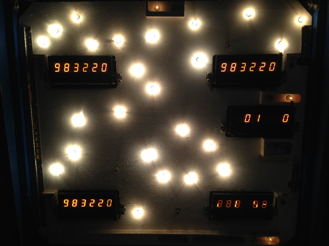
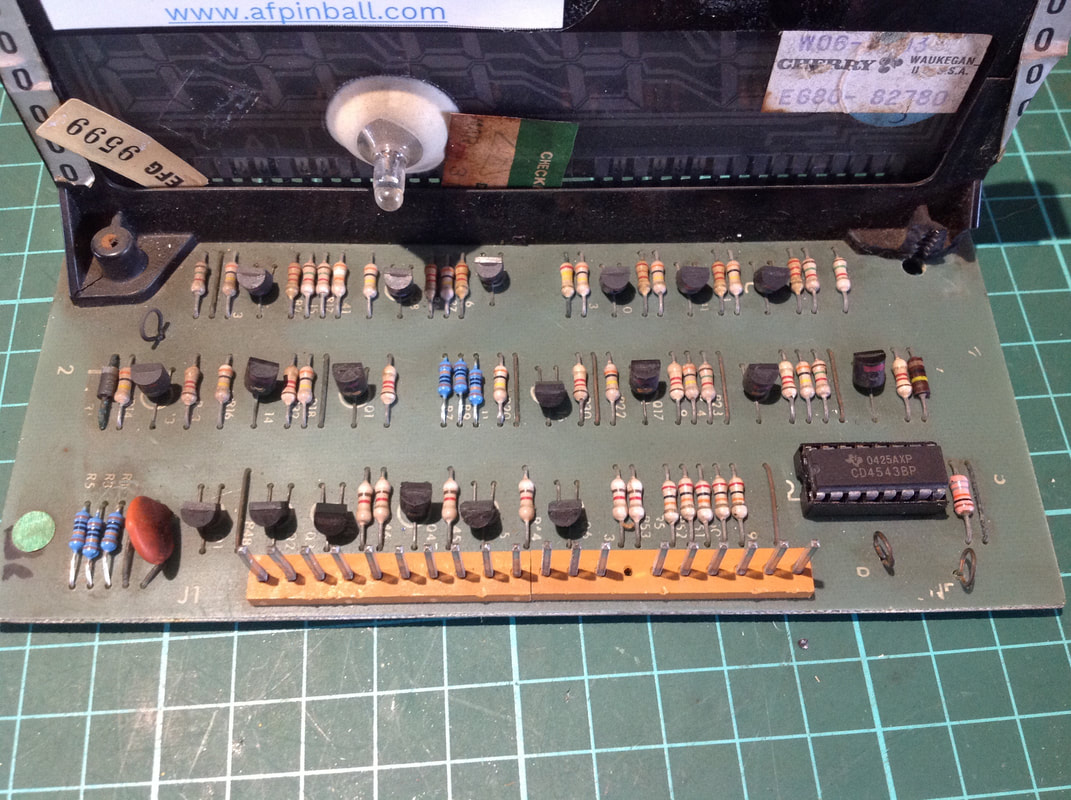
Steve Kulpa's website has all of the information you'll ever need to know about repairing Bally displays and I used this as a guide to troubleshoot the problem. First off, I moved the display to another position to confirm that the issue followed the display. It did. Then I did the basic bulletproofing of replacing the six 100k ohm resistors with larger wattage equivalents. Still no change. At this point, none of the symptoms listed on Steve's website, or anywhere else I could find, actually talked about my specific issue. However, the decoder integrated circuit on the display circuit board is responsible for telling the display which segments to light and when. I figured that this inverse displaying of digits was a data issue associated with the decoder. I replaced the decoder (Jaycar) and socketed it. That fixed the problem, and the display worked normally again.
Inverse display is on the bottom right (installed in a Star Trek for testing).

New decoder IC and resistors installed.
Fiona had recently found some great "glue" called Bondic. There are plenty of posts on Pinside where people have had success using it, or similar ultraviolet-curing welding resins, on plastic items that don't come into contact with the ball (i.e. don't need to resist direct ball impacts). Since this broken plastic is a part of the top arch and should never contact the ball, this seemed like a viable repair option.
The Bondic is simple to use, although the ultraviolet torches that come with it are crap. I used my own UV torch with a bit more power to help things cure more quickly. Ultimately, it took a few coats to build up enough strength, but the plastic held together strongly and doesn't look like it will break anytime soon. The Bondic does yellow slightly and since the edges of this plastic were quite broken, there was not a seamless join between them. However, it looks much better than the broken original! For those that are anal about their plastics, or who just want an upgrade, new sets are available (CPR).

Original broken plastic.
Repaired using Bondic.

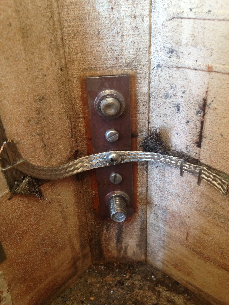
Luckily, I had a spare leg bracket in my parts box (also available from RTBB, PSPA, Mr Pinball), which was the same as the original. I had to break the ground braid that ran across the old leg bracket, so I installed a new length and stapled it to the old ground braid run and checked there was good continuity between the straps. Ensure you screw through the ground braid when screwing in the leg bolt, or alternatively, thread the braid behind the leg bracket, to ensure the leg bracket is grounded.

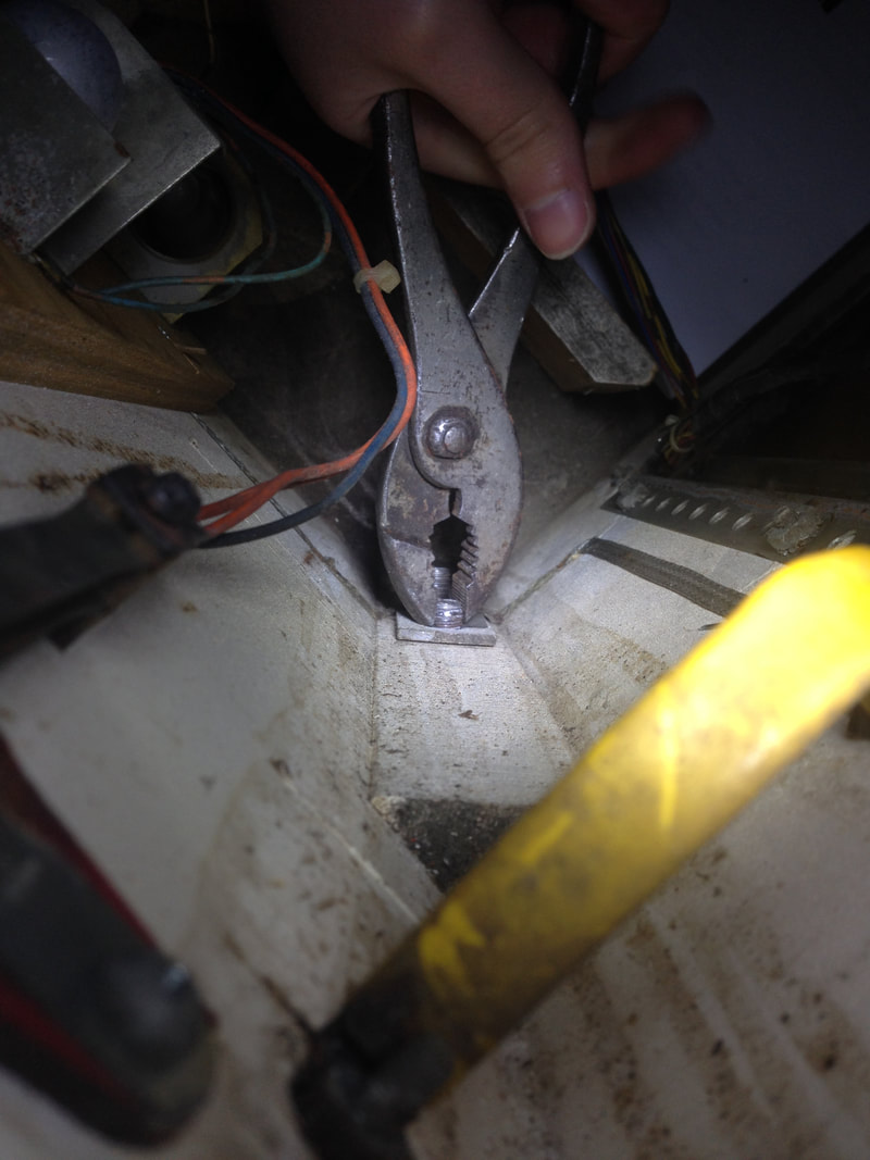
Removal of the old, stripped leg bolt.
New leg bracket and bolts installed with new ground braid.
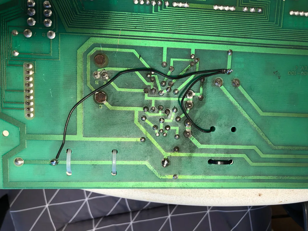
Jumpers on the rear side of the board connecting C23 and C26 to ground.
New capacitors installed at C23 and C26.

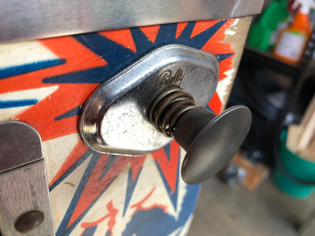
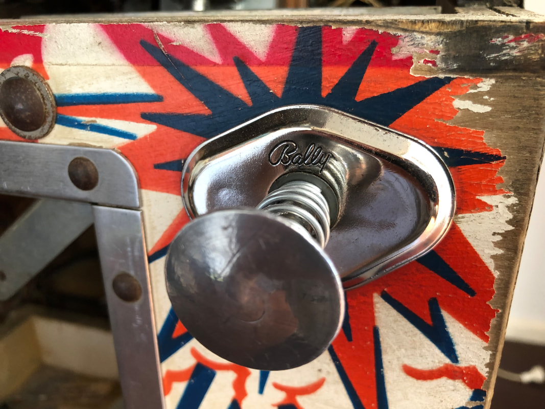
Ball shooter housing as received.

Shooter housing and shooter rod after a polish.
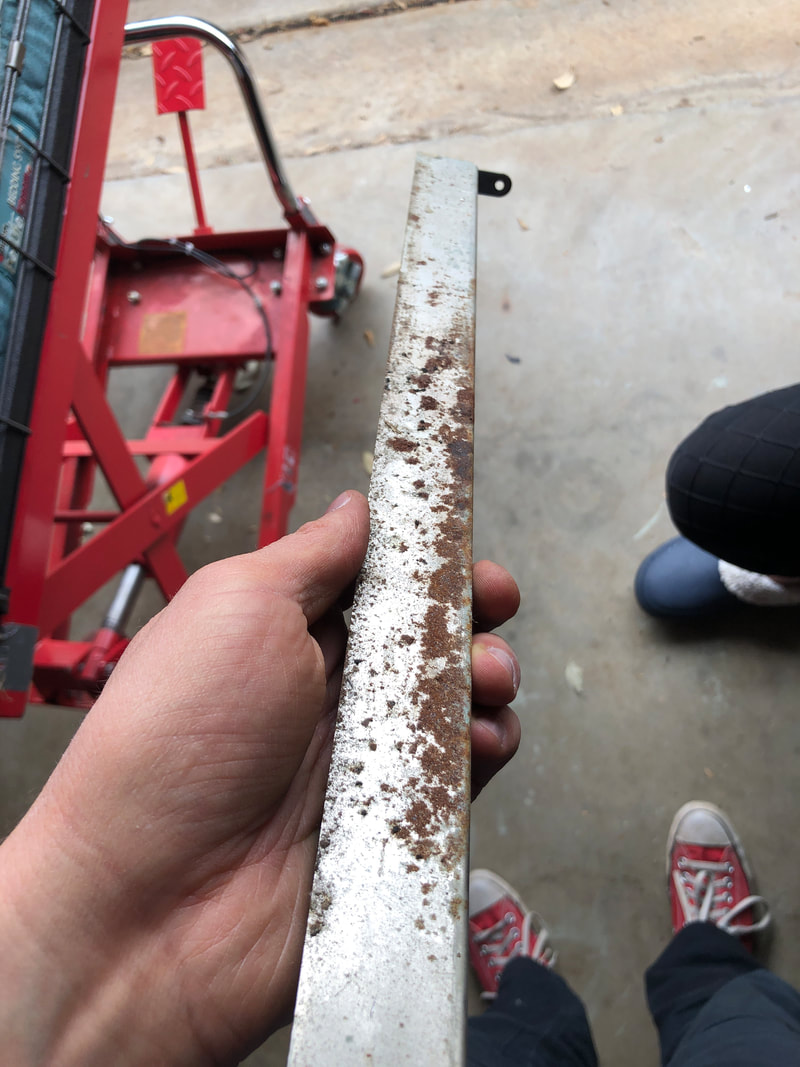
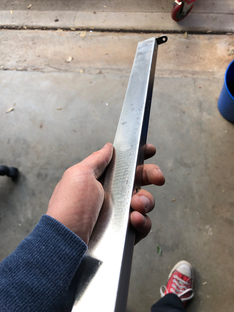
The next part I polished up was the playfield glass channel at the top edge of the playfield. Admittedly, this is a part that hardly anyone ever sees. However it often gets rusty and manky from things spilled on the playfield glass and general grime accumulation. If anything, cleaning the channel keeps the machine rust-free, which is a good thing. A layer of clearcoat on top of the polished metal will seal the previously rusted spots.

Rusty playfield glass channel.

Polished and clearcoated. Shiny!
After the parts had been cleaned and serviced, the machine was back together within a couple of hours. One of the joys of working on classic Bally and Stern games is that they really aren't very complicated games. This means there's not too much to take apart and reassemble, so things can move quite quickly.
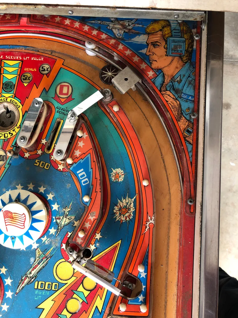
The extreme wear on this game's playfield was unfortunate but it was not something the owner wanted to bother repairing. Games with lots of inserts around the flippers often suffer from this problem as the heat from the insert lamps will raise or lower the inserts, and the playfield will start to chip from the ball rolling over the uneven surface. For playfields such as this, playfield protectors are available. Unfortunately, this playfield has not been reproduced, so repainting is the only way to restore the artwork.
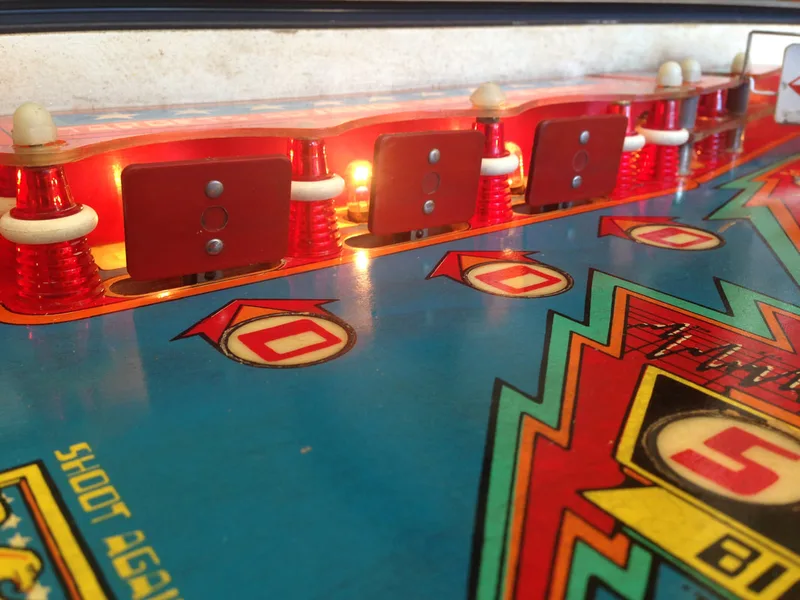
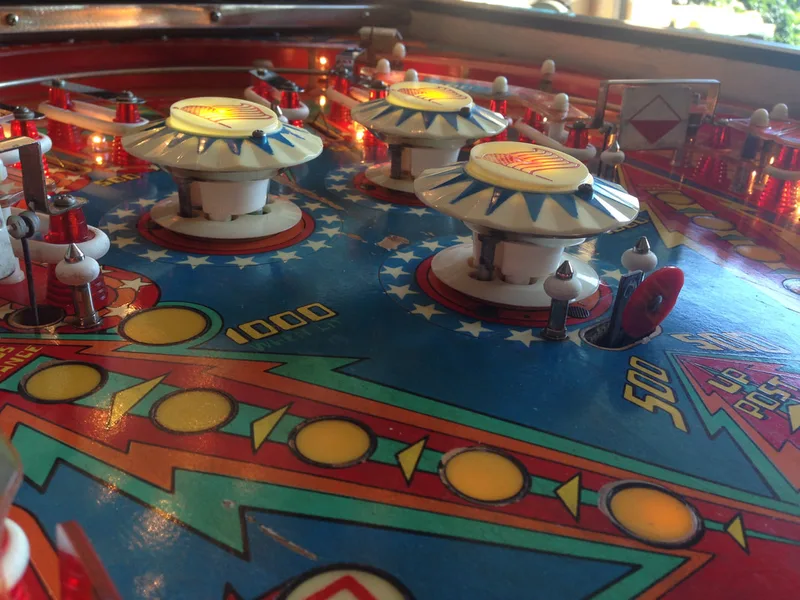
Like most Bally games, Six Million Dollar Man relies heavily on good pop bumper action so make sure you give these bumpers are good work-over. Second to that are the drop targets, which are crucial to getting extra balls and lighting the spinners for 1000 points per hit. Bally drop targets, or "Bally bricks", are unreliable at the best of times, so they need to be clean and free of obstructions to operate as reliably as possible.
I enjoyed testing the machine before it was time to deliver it to the customer. While the sounds aren't the most enjoyable for me, the flipper play on Bally games is pure pinball fun. Hopefully this machine lives on for many years to come.
After such a long time in storage I would recommend that the entire machine needs to be refurbished. This should include refurbishment of the circuit boards. I suspect your main issue is with the rectifier board and the MPU. Start by checking voltages at the rectifier board test points. If they are bad, suspect a component on the board or one of the connectors to it. If they are good, check for 5v on the MPU board and solenoid driver board. If it is missing you will need to trace the signal back to find out why. Hope that helps!
We recently moved our six million dollar pinball machine. Labled everything before removing the head etc. Put it back together but forgot to attach the ground which blew the F5 GI fuse. Took care of that, now the GI works just fine. We are now experiencing a failure of the bumpers setting during startup and the kickout putting the ball in play and the red light for a free ball is constantly lit. Would you know what I should look at before I dig too deep. I bet it is something really simple since it all worked before transport. All fuses look fine, but if you know which one to replace (I think it is F3 and replaced that one) I will try that again. Thanks for any assistance.
Glad you got the first issue sorted. I would suspect an issue with the communication between the MPU and the lamp driver board, as the MPU appears to be working based on the flash codes. The connector between the boards may need to be rebuilt, or there may be a bad solder joint somewhere along the path. Wiggling the connectors on either end may help narrow this down.
Also check to ensure your voltages coming from the rectifier board are all within spec. Problems here will manifest in weird ways down the line.
Hope that helps!