- Published on
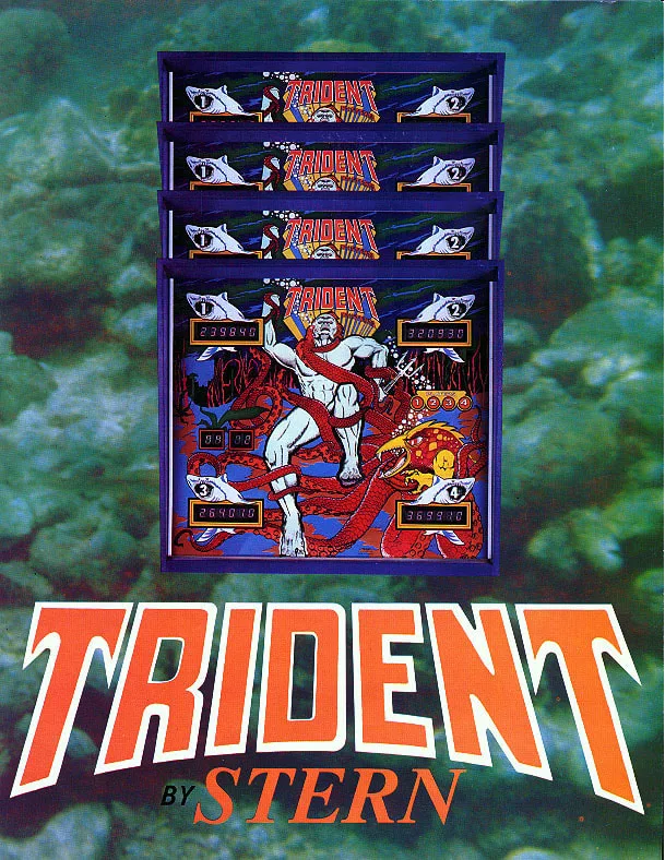
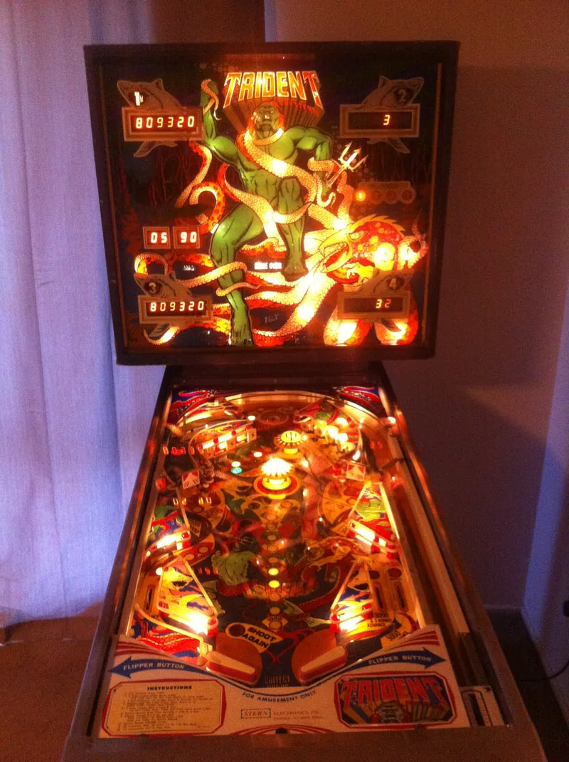
Trident
- Author
-
-
- Name
- Posts
- Posts
-
Initial condition report (click on sections below to view details)
- Timber in good condition. Lots of scuffs and marks.
- Headbox missing two bolts.
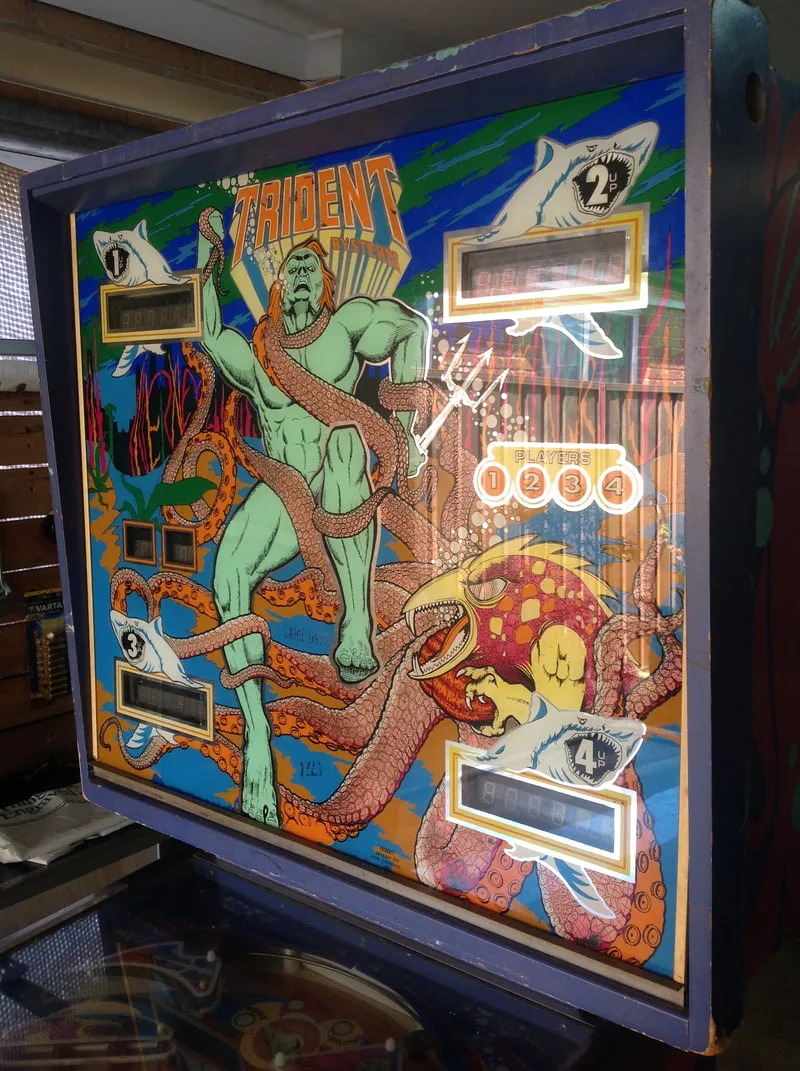
- Backglass in poor condition; bright colours were faded and paint was flaking off.
- Playfield was dirty.
- Consumables (rubbers and lamps) mostly intact and in good condition.
- Playfield artwork in poor condition. Wear below saucer at top of playfield. Most inserts slightly cupped.
- Plastics in perfect condition!
- Playfield mechanisms in good condition.
- All mechanisms and assemblies very dirty. Some metal parts broken.
- Consumables (coil sleeves, flipper parts) dirty and in poor condition.
- Machine booted but could not start a game.
- Playfield and backbox wiring in poor condition. Various wiring hacks present throughout the game.
- Printed circuit boards in poor condition. Severe battery leakage.
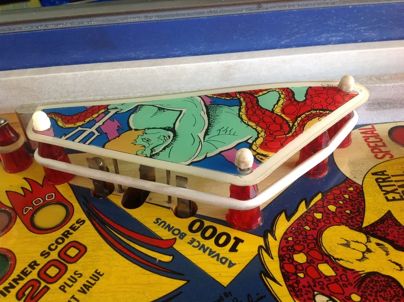
Apart from the apparent burned out coil, the game was actually in very good cosmetic condition. The playfield was a little dirty with some inserts cupped and some damage to the playfield near the saucer, but the cabinet was still nice and sturdy and the plastics were in fantastic shape. They almost looked brand new and were bright white on the edges. I haven't seen plastics on a game this old in this kind of shape before. At least I won't have to worry about replacing any! However, there was an ugly side. There was a lot of electrical work to be done on this game as the wiring had been hacked up in various spots. This would be where most of the work was involved. I decided to give the machine a clean first and do a couple of cosmetic repairs before getting into the nitty-gritty of the electrical repairs.
Disassembly
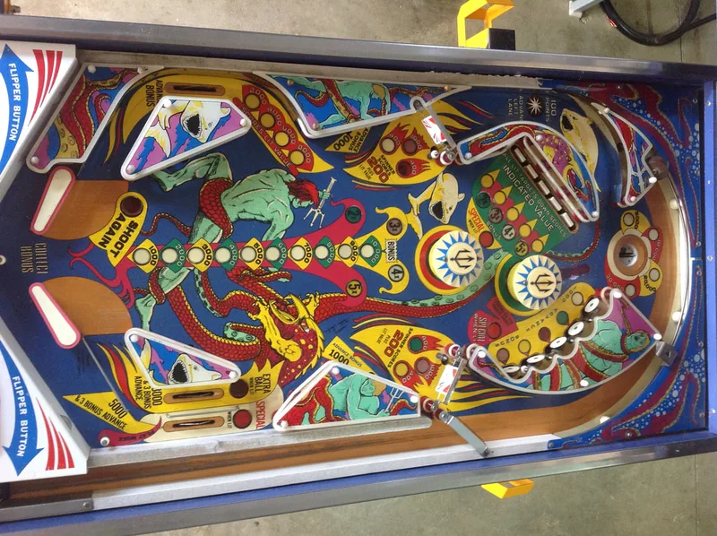
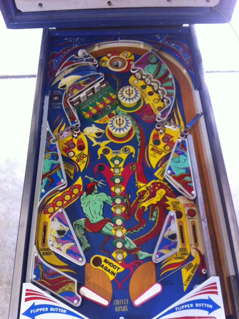
Like most classic Stern games, Trident is simple machine with a single-level playing field, no ramps, and no weird playfield mechanisms. Playfield teardown is relatively simple as long as you take photos to remember where everything goes.


After disassembly, the game went through my standard restoration process to get it playing and looking like new. During the restoration process, I dealt with a number of issues, described below.
Tips & Troubleshooting (click on sections below to view details)
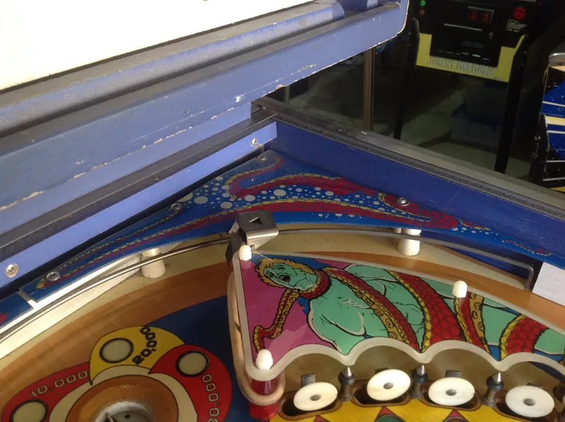
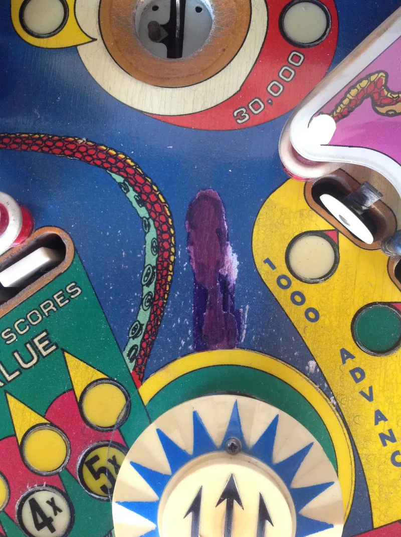
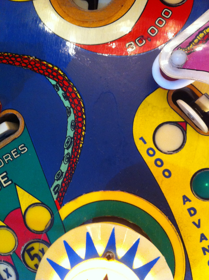
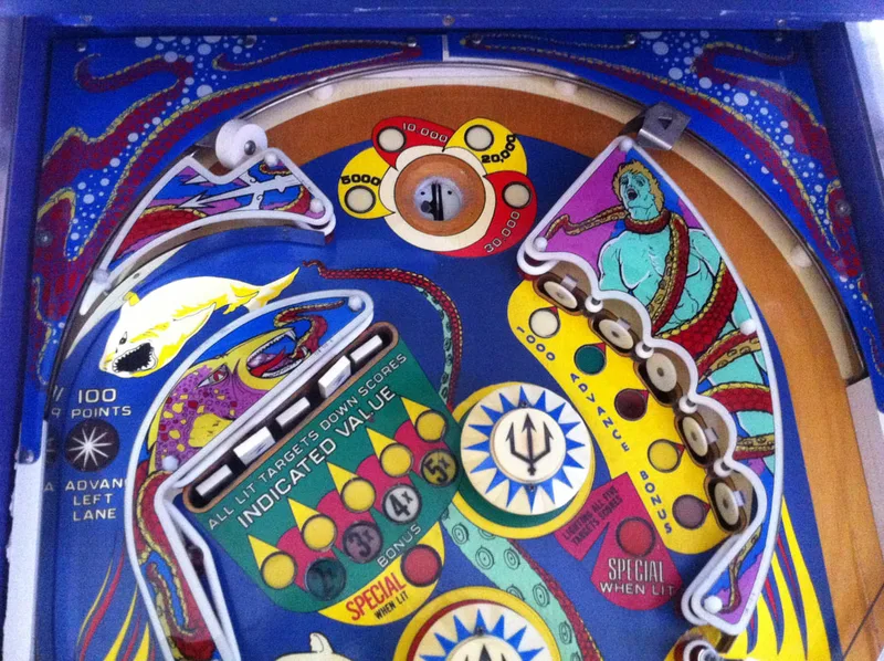
The wear on this machine had worn away the artwork, exposing the wood underneath. Somebody had tried (unsuccessfully) to cover it up with what looked like a permanent marker. It was ugly. So this was a good occasion to Fiona to whip out the paint brushes and make it look good again. This area is a single blue colour so no intricate artwork to reproduce. We used Createx Opaque Blue paint, with some Opaque Black mixed in to give it a slightly darker shade. That's all we needed. Fiona hand painted it and extended the painted area slightly further than the damage, to give the area a more consistent look.
Initially, the customer wasn't too concerned about this area and didn't want to bother having it repaired, but the end result was great and he was very happy with it.
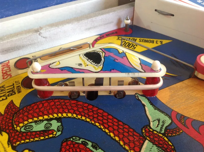
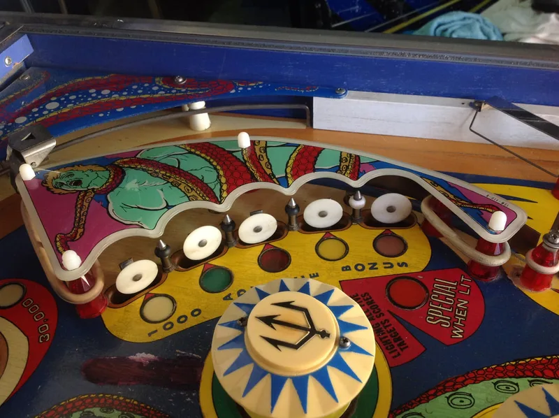
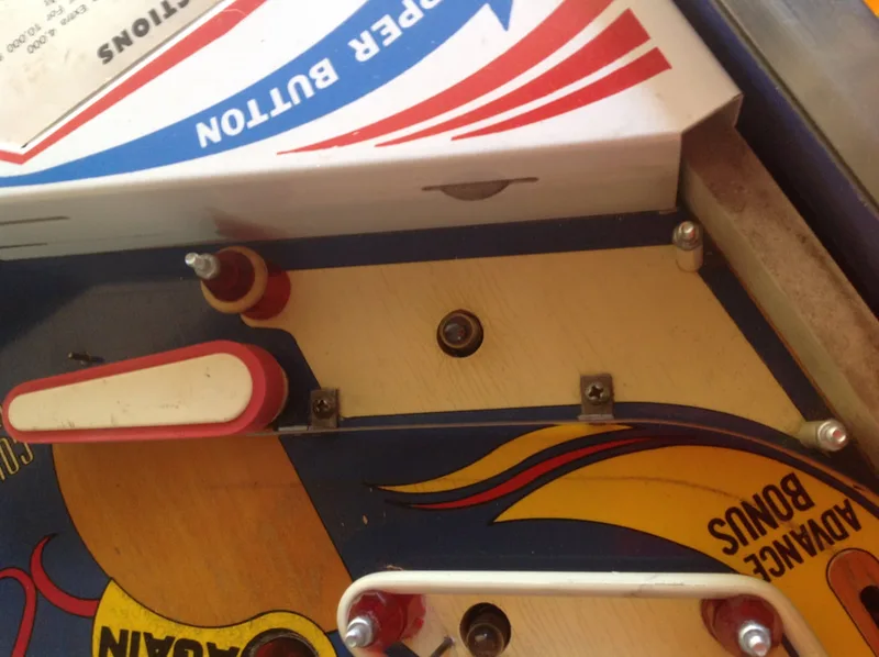
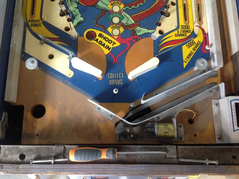
Before repair. Balls kicked out of the saucer land here and then get smacked by the pop bumper.

After repair. Repainted and looking much better.
Other than that, there were some minor touch-ups made to most of the insert borders, which had faded or chipped away. For this, we just traced the outline of the inserts with Createx Opaque Black.
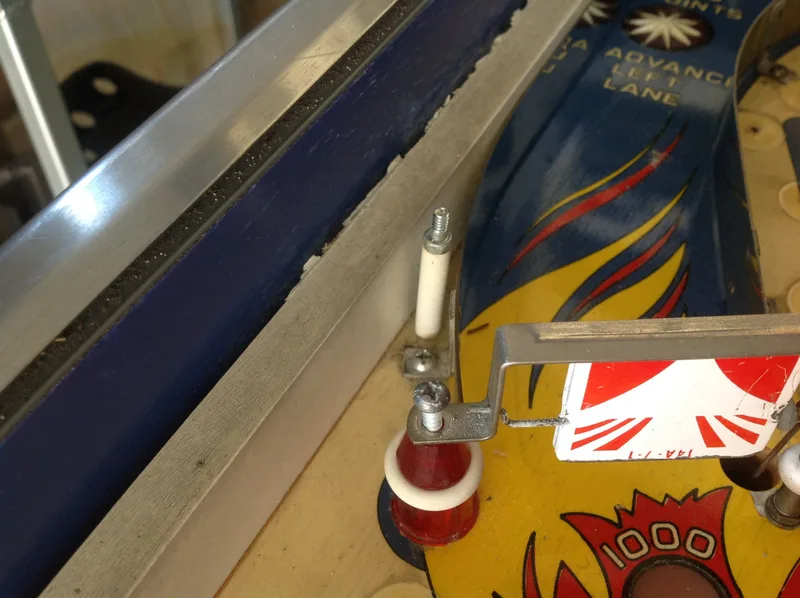
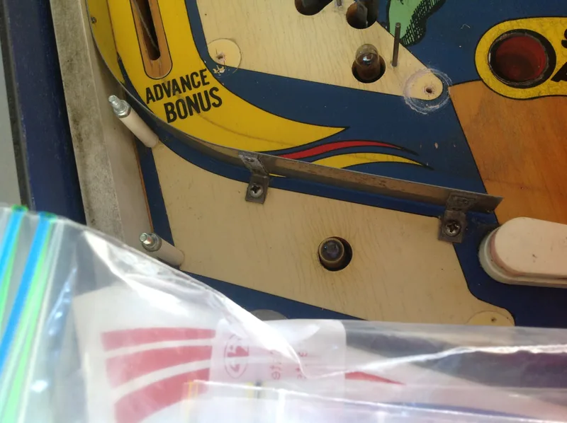
But there was one part that I couldn't find a replacement for: the left flipper mounting plate. These mounting plates are badly designed with one tiny section joining the two halves of the plate together. With impacts of the flipper plunger against the coil stop, force is exerted on this section and it breaks as there is so little metal there. These aren't regularly available anywhere in Australia and the customer did not want to wait for a replacement, so as a temporary stopgap I used a woodscrew in the playfield to hold the bracket in place. It held the bracket in well, so it should be good until a new bracket can be installed.
Broken flipper mounting bracket. The break is visible at right.

Dodgy wiring to the line filter in the cabinet. One section has just had proper insulation added while the other is still covered in electrical tape, awaiting removal.
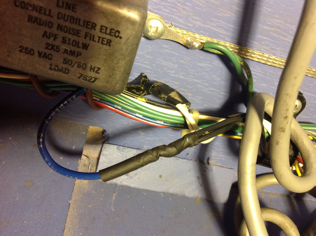
Following power further into the cabinet, there were some pretty serious hacks to the rectifier board - I'll deal with those in the next section. The wiring was otherwise OK until the backbox. One of the backbox connectors to the MPU board (top left) had every wire leading to it wrapped with electrical tape. The connector had obviously been replaced at some point in the past by someone cutting it out and replacing it with another from a different game. Most of the joints held together by the electrical tape weren't even soldered together; they were just held by the tape. Yuck.
I have no idea why someone would go through all of the effort of joining each wire and then wrapping them in tape when it would be less effort to replace the connector. The connector was in good condition so I decided to solder each of the wires properly and insulate them for better protection.

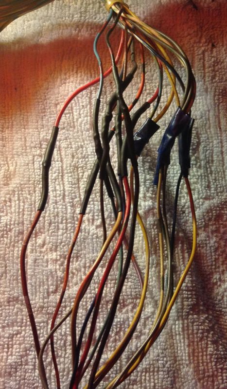
Soldering and insulating wire connections; ones at left have been done while ones on right have not.
After fixing the wiring hacks here it was time to move onto the rectifier board, which needed a lot more work.
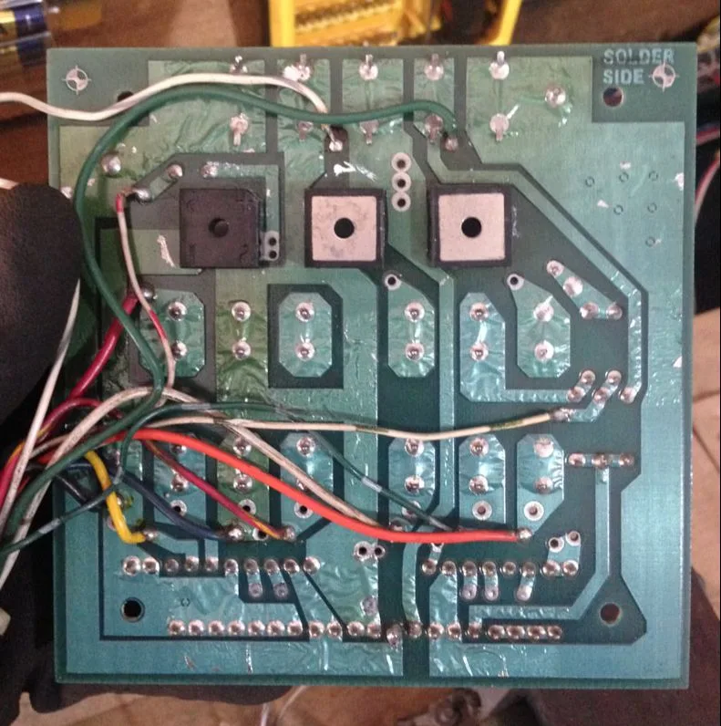
Before I could do any repairs to the board, the first thing I had to do was get it out of the cabinet. This job was hard when someone has soldered the connector terminals straight to the header pins on the board...

View of the front of the rectifier board in the Trident. Ugly!
Lots of things wrong with the board in the image above. The most obvious was that the connector on the bottom of the board (J3) had been split in half and the centre portion of it was no longer present. It probably got brittle due to overheating and broke away at some point. Obviously, the last person to have the machine did not have the time or the patience to repin a new connector, so they soldered the connector wires directly to the header pins of the board. Then, there was the nice touch of the automotive screw terminal connector. It can't be seen in the photo above, but a couple of the fuses on the board were also above the specified amperage rating. Perhaps that is what caused the J3 connector to overheat in the first place. Suffice to say, there were lots of things to look at for repairs. After cutting the wires that were soldered to the board, I could finally take it out and get a look at the rear.
Rear of the rectifier board after removal from the cabinet.
All things considered, the rear of the board looked quite good. It looked like somebody had replaced one of the bridge rectifiers (large squares at the top of the board), but otherwise the board was fairly clean apart from some solder mask lifting and some heat discolouration.
At this point I had to decide whether to repair the old board and whether this was a better use of the customer's money than buying a new board. As is usually the case with these older, decaying boards, repairing them just isn't economical if you're doing it for a customer. It's not worth the time and stress having to replace most of the board's components and reflow most of the solder pads when there are nice, reproduction boards available for a cheaper cost than the labour of fixing the original board. So that's what I did in this case. I grabbed a new Rottendog rectifier board. There are a couple of other manufacturers of similar replacement rectifier boards (including an Australian supplier, Austral Amusements), so shop around if a particular one isn't available.
When reconnecting the new rectifier board to the transformer outputs, you'll basically need to resolder the transformer outputs to the new board and then just drop the board back into the cabinet where the original was. Easy! A picture of the old board's layout is very helpful with this step; you don't want to miswire the board! Schematics can also help you wire the new board correctly, and there is a great description on Pinwiki of where to solder the various wires.
After I connected the new board and installed a new connector for J3 (as the original one was in pieces), I ran into a couple of issues. According to the schematics, there are meant to be two separate wires from the transformer to E7, and another two from the transformer to E8. These are the 7.3 VAC connections for the general illumination. My game only had one wire going to each spot. The wire was a little thicker than the others, so perhaps when these games were assembled they decided they could use one thicker wire instead of two smaller ones. In any case, it doesn't hurt to add another wire, so I ran two lots of wire to E7 and E8.
Another thing that confused me was that there was no wire for connector J3, position 13. According to the schematic, this wire is meant to be for a solenoid connection. This wire is actually only connected on games where the knocker is located in the backbox. This wire leads to that solenoid. Trident, on the other hand, has a knocker in the cabinet, so power doesn't need to be fed into the backbox via J3. Instead, it goes straight to the knocker from connector J2, and no wire should be connected to J3-13.
If you're feeling adventurous (and have lots of time!), Corey's fantastic thread on the MAACA forums covers the process of rebuilding of an original rectifier board. This helped me out with another issue when I first booted up the game with the new rectifier board installed. Test point 2 was only reading 183 volts, when 230 volts was expected. This is the circuit that powers the score displays. According to Corey's guide, a lower voltage is expected when there is no load on the circuit, as was the case when I tested it. So, no problems there.
After testing all of the new rectifier board's test points and verifying they were all OK, I connected the rest of the backbox boards and turned it on. Hooray - successful boot into attract mode! Power supply was steady and working, which was much easier than it would have been trying to rebuild the old supply!
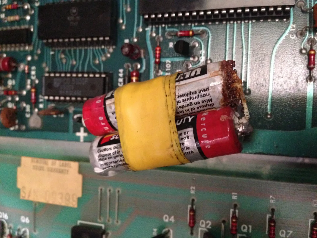
Severely leaking batteries on the MPU board.


Severely leaking batteries on the MPU board (side view).
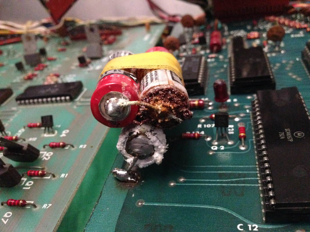
Classic Stern games were built with NiCad batteries mounted to the MPU board. The original battery had been replaced by three AA batteries, wired in series, and held together with electrical tape. Very ugly. However, the bigger problem was the extreme alkali leakage which was evident. All of the batteries were leaking and some of the corrosive electrolyte had made its way to the base of the board. These batteries were cut from the board and the leads completely desoldered. After that, cleanup could begin. Cleaning electrolyte from circuit boards is done via neutralising the alkali with an acid. There is a great write-up on this topic on Pinwiki. I used some vinegar to neutralise the alkali and scrubbed the area clean with a cloth and isopropanol. Luckily, the corrosion had not spread past the battery solder pads on the board, so there was not a lot to clean up and no other components needed replacing.
Next step was to replace the batteries. Once again, there is a great rundown of battery replacement options on Pinwiki. I opted to install a remote battery pack. I used a four-cell AA battery pack and installed a blocking diode across the first cell slot so the batteries wouldn't get charged. Then I put three new lithium AA batteries in and it was good to go. This way, the customer can just replace the batteries themselves, and the lithium cells are much less likely to leak.
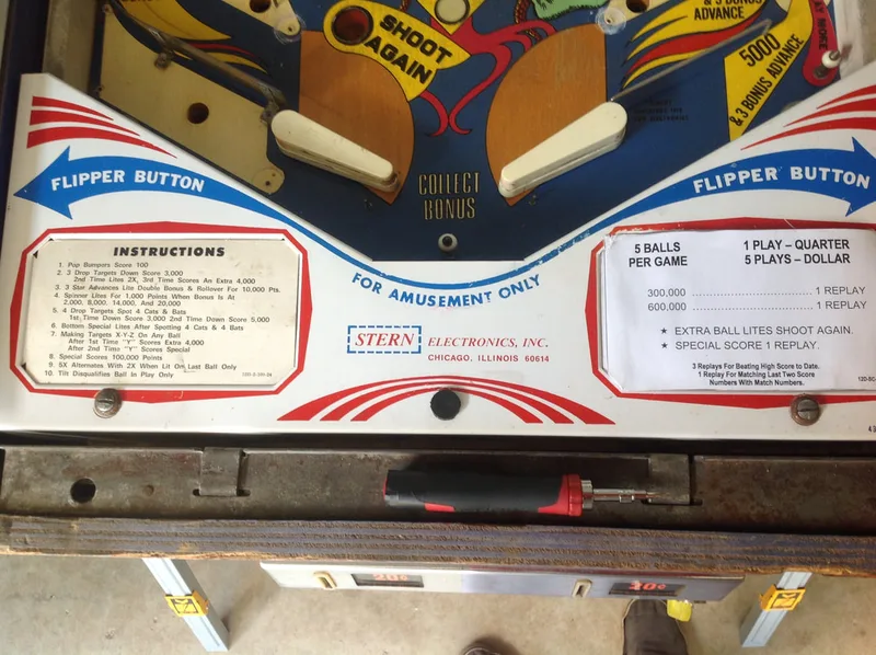
The customer wanted to set the replay score to a more achievable level. I looked through the manual to see if there was a setting to control replays. The only one I could find related to switch settings set via the toggle switches mounted to the MPU board. Switch 6 turns replays on or off, but there's no switch for setting the replay score.
This is actually set in self test mode and changing this setting is described on page 4 of the game manual. You can enter self test mode using the button on the inside of the coin door. You can set three replay levels. So once I found the correct self test option, setting the replay scores was easy. It always pays to have a manual!
This pointed to some kind of wiring or connector issue as the components controlling the lamps wouldn't stop and start working for no reason. I reseated all of the connectors on the MPU and found the issue. The lamps are controlled via signals through J1 and J4 on the MPU. Wiggling these connectors caused the lamps to start and stop working. And that was the issue. The .100" header pins and connectors on classic Stern games are very unreliable as they are vulnerable to cracked solder joints. Reflowing the solder on these joints made the lamps start working reliably again.

Pop bumper coil which had locked on and melted.
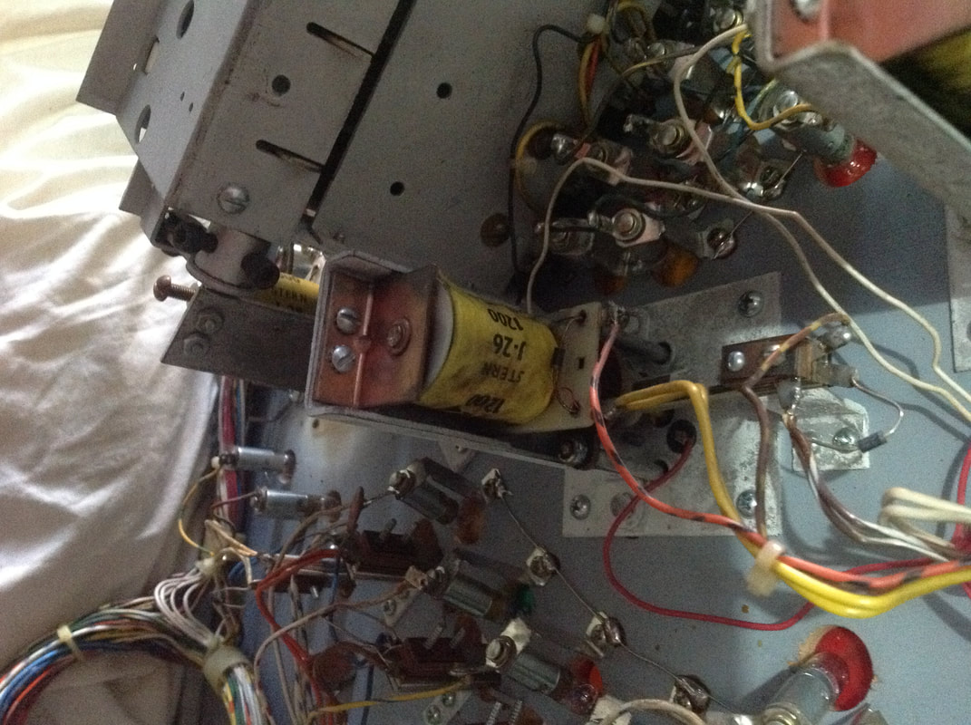
You can't tell from the outside, but this coil had melted and locked the plunger in place inside the coil. I didn't grab a picture of it after disassembly, but it was a mess; totally melted and not salvageable. At this point, I had to order a new coil and wait for it to arrive in the mail. Not many places in Australia stock many classic Stern coils. I grabbed one from Austral Amusements. If you want to continue testing and using the game without one of the coils, you need to remember that all of the coils are daisy-chained together via the thick yellow wires. That's why there are multiple wires on one of the coil's lugs. Keep these wires connected to each other so that current can still pass through to coils further down the chain, or you will have other coils not working throughout the game. Often, one of these wires has come loose from the coil lug, which causes multiple coils further down the power train to stop working. If you're leaving loose coil wires in the cabinet, it's a good idea to tape up or otherwise protect these wires, as they can damage the boards if they short against other playfield components.
Soon enough, the replacement coil arrived in the mail. Before installing it, I had to figure out what caused the first coil to fry in the first place. As the coil had locked on, this was a good indication that the transistor controlling it may have failed. Pinwiki also has a section describing transistor testing for this purpose. After testing all of the transistors on the solenoid driver board, I found one was faulty. It was Q2, which controlled the pop bumper according to the schematics. I replaced it with a TIP102 transistor, which is more robust than the original SE9302 transistors used and is the recommended replacement. The diodes and resistors associated with this coil tested OK, so they were left intact.
I booted the game up to test it and the pop bumper didn't immediately activate. Good sign! In solenoid self test, the pop bumper activated as expected. Success!
The right side spinner on Trident (part no. 14A-7-2) was not working well. It was slow to spin and felt uneven. After disassembly and a good clean, it was working better, but still not perfectly. Some suggest using lubricant, but I'd prefer not to. Comparing it to the spinner on the left of the playfield, I saw that there were a couple of issues. First, the wire connecting the spinner to the switch under the playfield was bent. I straightened it out and readjusted the switch blade it connected to. Next, I had to straighten the spinner target itself. The wire supporting the target face had bowed out, and needed to be bent straight. After these two fixes, the spinner started spinning like there was no tomorrow! Note that if you ever need to work on these spinners, original spinner assemblies are totally unobtanium now. Even PB Resource no longer stocks them. So don't lose them, and don't bend the wires too forcefully. Too much force or too much flexing makes the wire brittle and it will break!
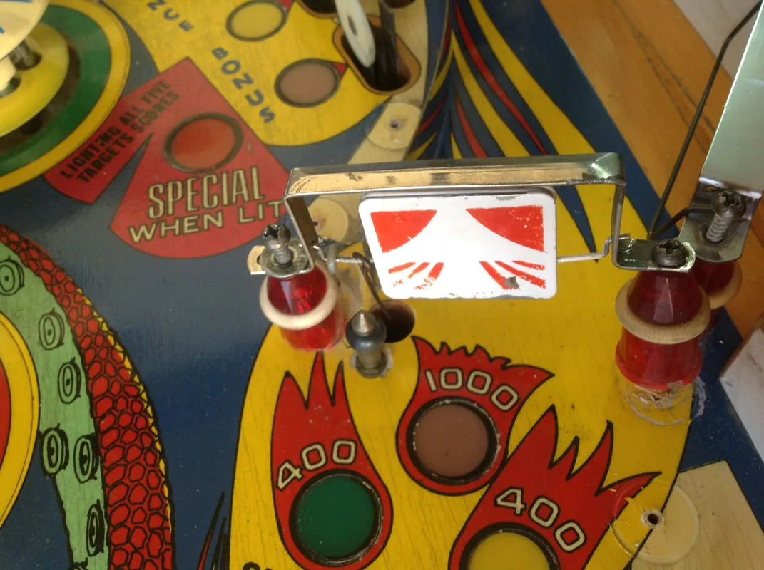
Right side spinner assembly with bent switch actuator wire and bent target support wire.

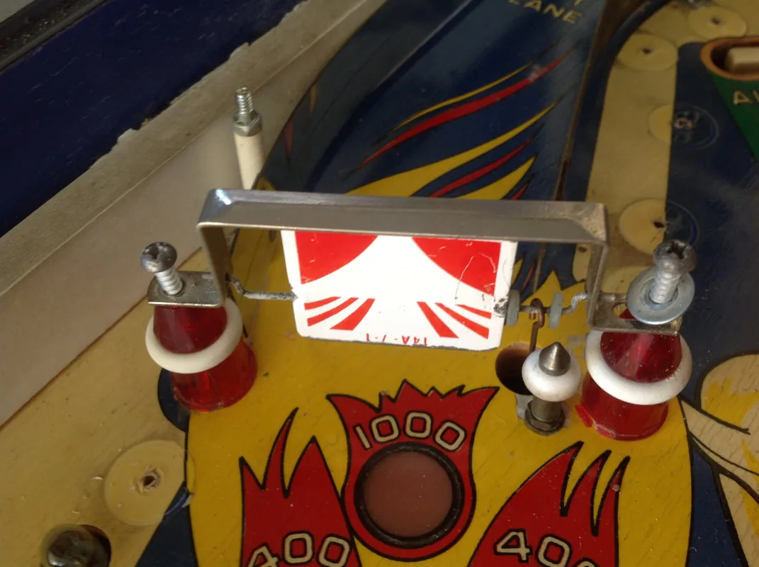
Left side spinner assembly; nice and straight.

Reassembly on Trident was a no-brainer; not much to it. The most complicated mechanism to reassemble was the drop target assembly, but it just needed a good clean and none of the parts were broken.
After replacement of the burned out lamps, there wasn't much else to do. The game was now booting up and playing. The one thing I customised was the pricing card, as the original was yellowed and tatty. This one just featured an image from the backglass, but it works well.
Conclusion
Working on Trident has set me up well for restoring my Stars down the track. I always like to check out images on IPDB of games I restore as a reference point. I was surprised to find that there were no images of LAI-built Tridents on the database at all. So, I submitted some of my own and they are now featured on the LAI Trident page. Unfortunately, they weren't the best shots, but I never took them with the intention of uploading them to IPDB!
I dropped the game off at the customer's house and set everything up. Everything worked well and the game looked good. More importantly, the customer was happy with the work and very happy with the total cost. And so ended my first classic Stern refurbishment!
It sounds like the game is in attract mode and needs to have a credit added in order to start a game. You can find a manual with details on how to start a game here: https://www.ipdb.org/machine.cgi?id=2644.
Hope that helps.