- Published on
Attack from Mars
- Author
-
-

- Name
- Posts
- Posts
-

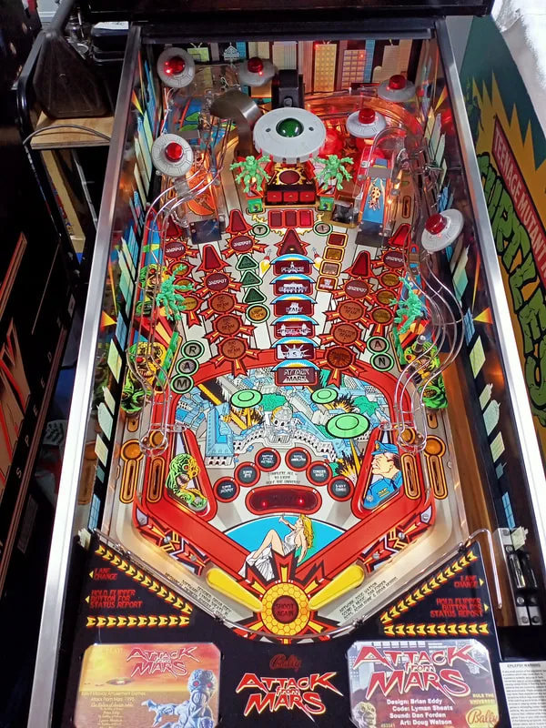
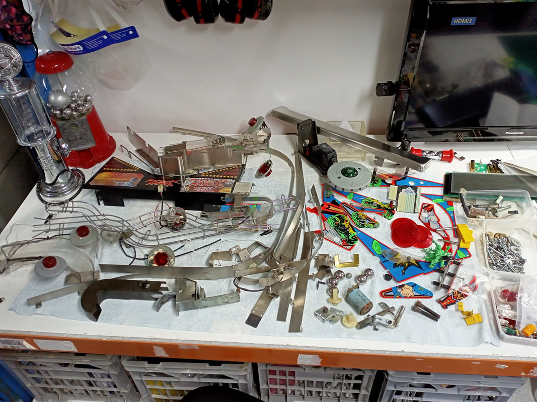
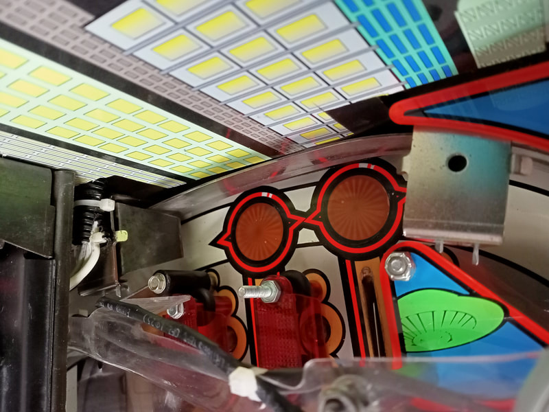
I wish this blog post meant that I had bought an Attack from Mars (Bally, 1995) and was restoring it for my own pleasure. But alas, no! This was a mini restoration for a customer who had purchased the game, taken it apart in preparation for restoration, but was never able to complete the project. So, I offered to help and get the game back together for the first time in over ten years. This project was a little different to previous restorations, as I was starting with a blank playfield and boxes of parts, with no reference photos of my own. Plenty of fun to be had. It helps that Fiona also loves Attack from Mars, so this was a good chance to give it a thorough playtest!
- Timber in great condition.
- Side art in great condition (new decals).
- Side rails and legs in great condition.
- Translite in great condition.
- Playfield a little dirty from sitting open for many years.
- Minor damage to some inserts, which had decals applied to them.
- Consumables (rubber rings and lamps) had been removed previously.
- Plastic and wireform ramps in good condition.
- Playfield mechanisms in average condition. Some in pieces, and some requiring repair. 3 target bank not moving, and switches not registering. Martian figurines missing.
- All mechanisms and assemblies in good condition.
- Popper assembly in pieces.
- Mini saucer lighting mod wiring was present but disconnected.
- Backbox circuit boards in average condition. Some heat damage to general illumination area.
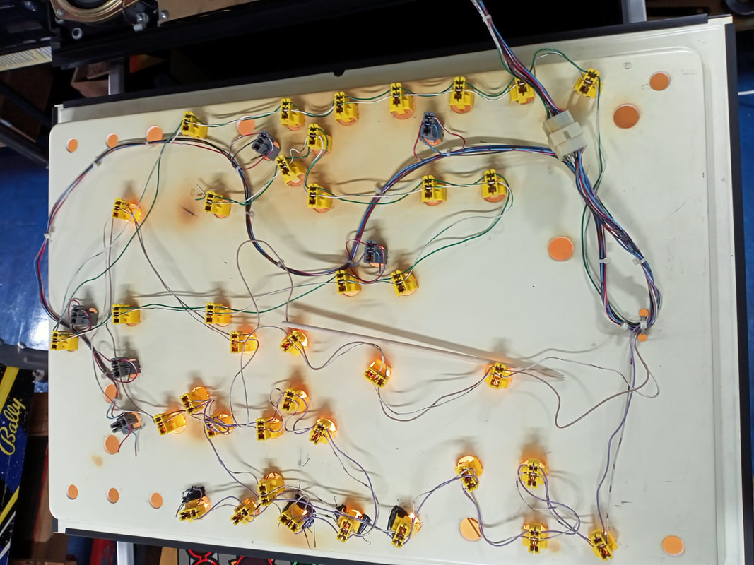
- Cabinet wiring in good condition.
- Game booted up but did not retain memory.
While the game did boot up, it was going to be difficult to actually determine what problems were present until the playfield was back together. All I could do at this stage was test a few playfield mechanisms, lamps, and switches. Some of these were not working, which required some further investigation. The playfield looked to be in average condition, with some inserts having been damaged and repaired with insert decals. Some playfield wear around the Stroke of Luck scoop had also been bogged with wood putty, and repainted. Playfield artwork repairs were not really the focus of this restoration, so I didn't worry too much about these areas.
There was no real disassembly stage to this restoration, as it had already been done for me! So, instead, I set about cleaning all of the parts in the boxes I had been provided, and laying them all out for assessment, pictures of which appear below. Then, I could begin to piece together what was there, and figure out what repairs were needed.
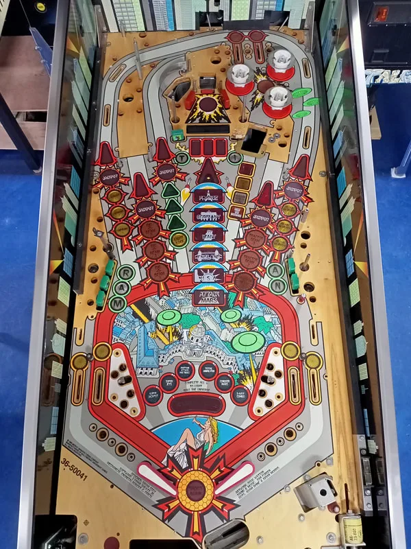
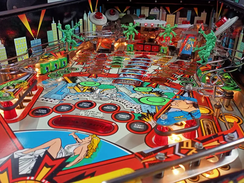
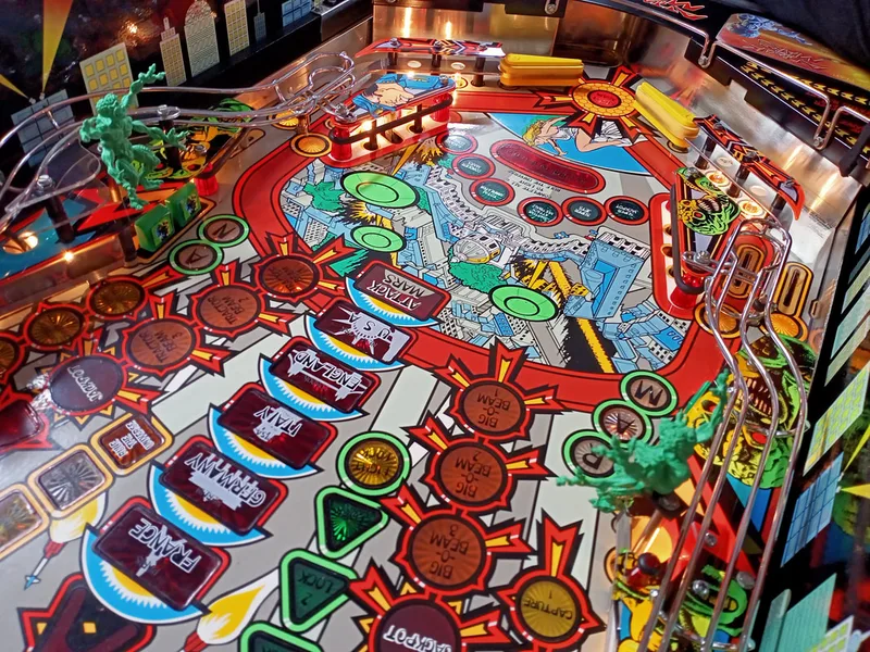
Playfield topside, as received.

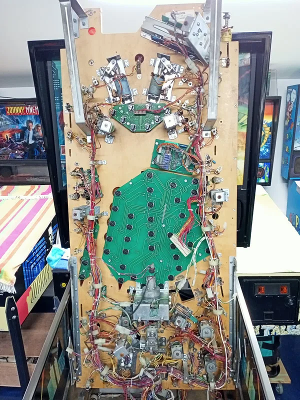
Playfield underside, as received.


All provided parts laid out for assessment.
After parts stocktake, the game went through my standard restoration process to get it playing and looking like new. During the restoration process, I dealt with a number of issues, described below.
Tips & Troubleshooting (click on sections below to view details)

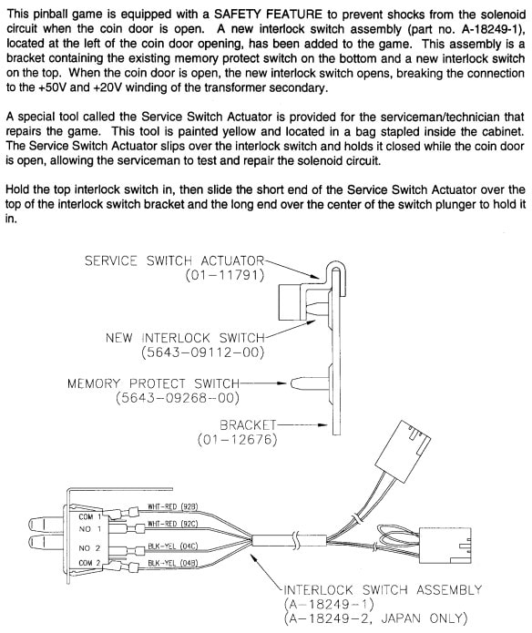
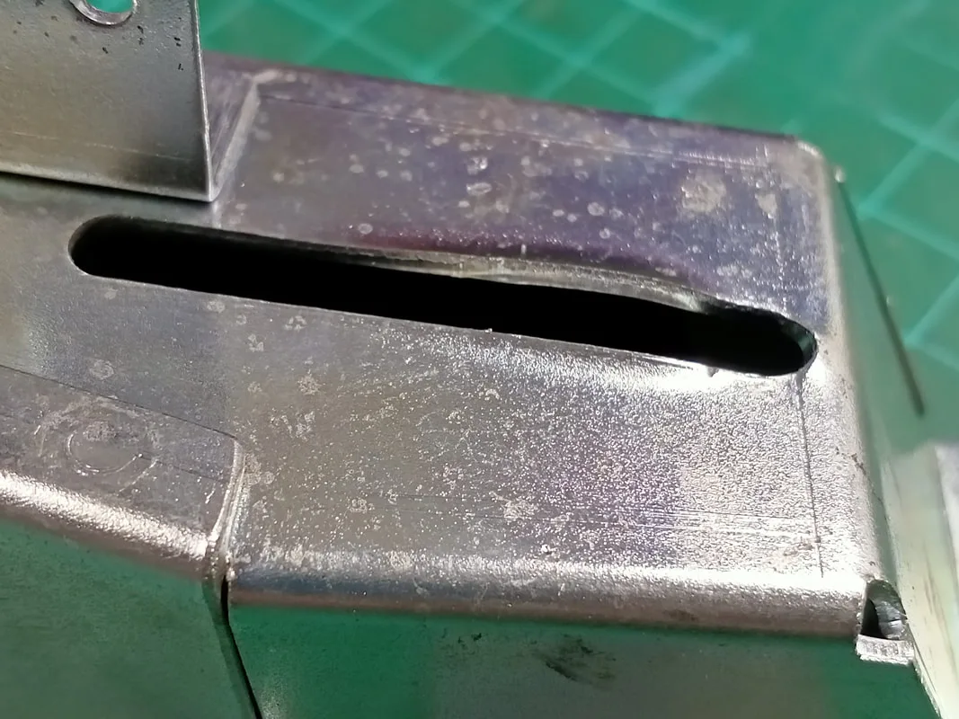
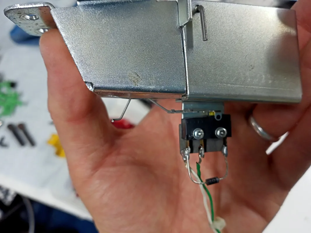
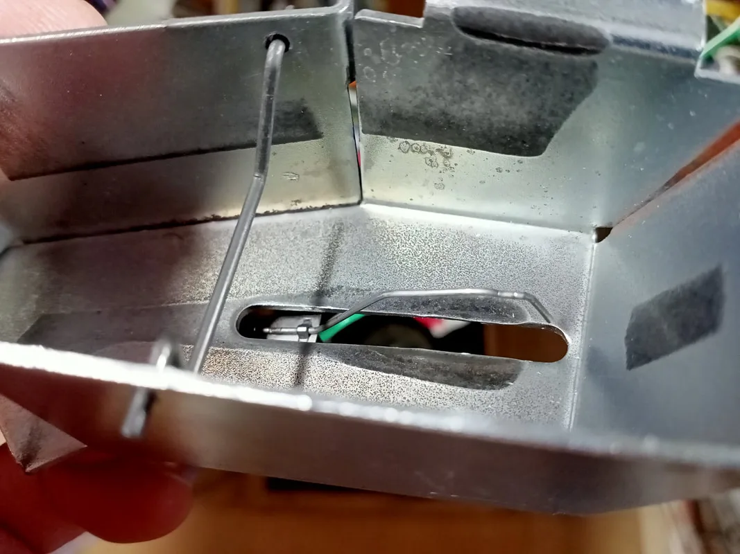
Excerpt from the game manual describing the interlock switch assembly by the coin door.
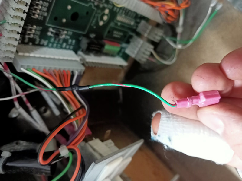
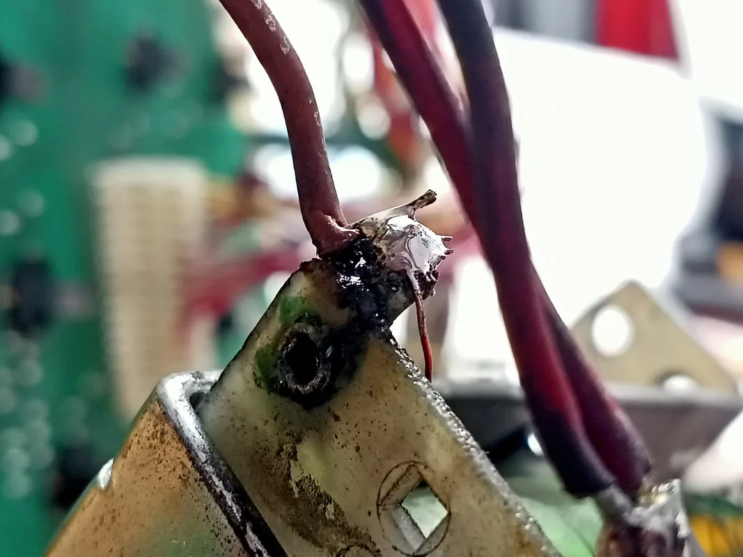
Some fiddling around with the switch assembly eventually revealed the issue. The green-red wire connected to this switch had broken. This wire connects the switch to the coin door interface board (J9-5). With this wire broken, the switch was hidden from the CPU. A bit of solder and heat shrink tubing fixed the issue. The coin door now registered as closed like it should.
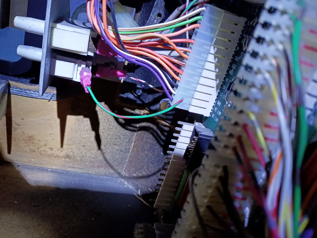
Broken wire for the memory protect switch.

Wire repaired!
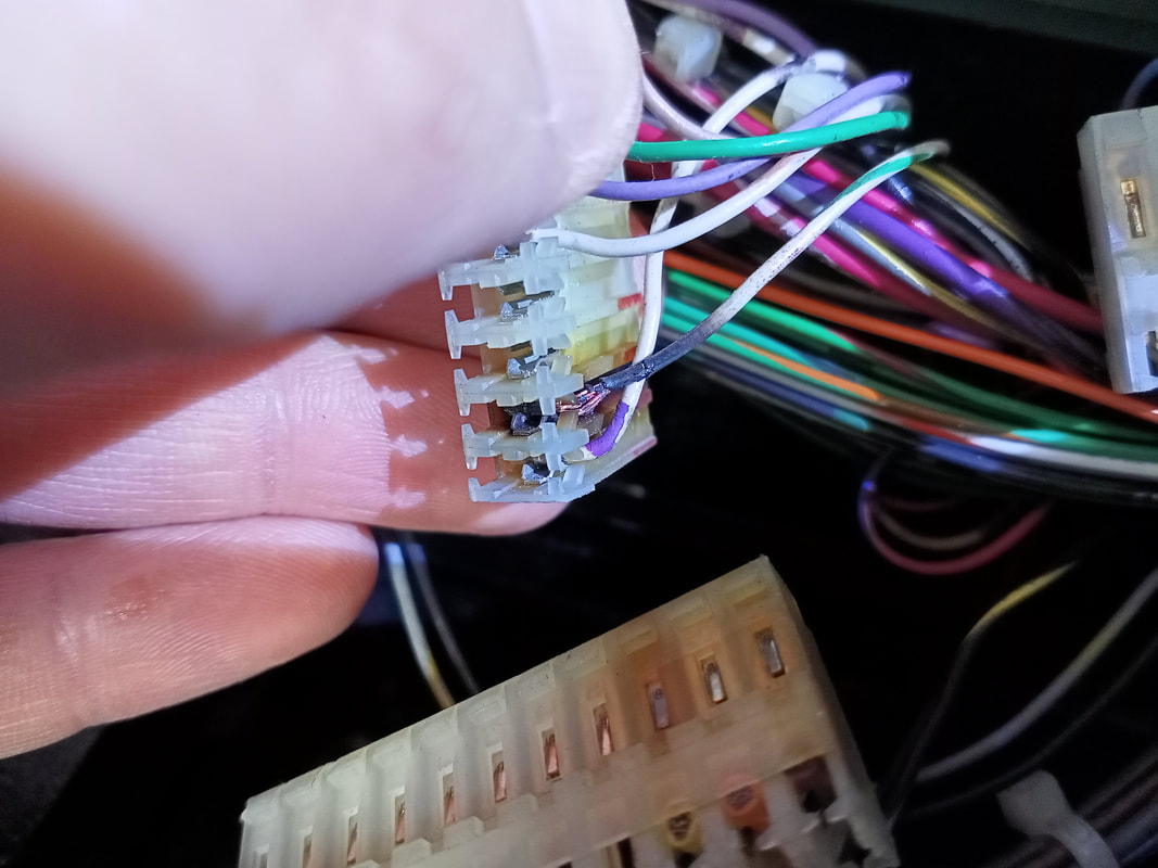
I hate WPC-95 backboxes with the plastic insert panel and IDC-style sockets. These sockets are terribly unreliable, and are often fragile or broken. I had to retention a number of the sockets as they were holding onto the lamps too loosely. The backbox lamps are on three separate GI circuits (green, violet, brown). None of the lamps on the green circuit were lighting up . The lamps themselves were OK, and the sockets didn't have any physical issues. Looking at the power driver board, I found the connector at J106, which supplies the backbox lamps, to be pretty badly burned. The white-green wire had fallen out of its slot, which was causing the lamps on that circuit not to light. I replaced the connector, as well as the general illumination J105 connector for good measure. The lights on all circuits then worked fine.

Burned GI connector at the white-green wire pin.
New GI connectors installed.

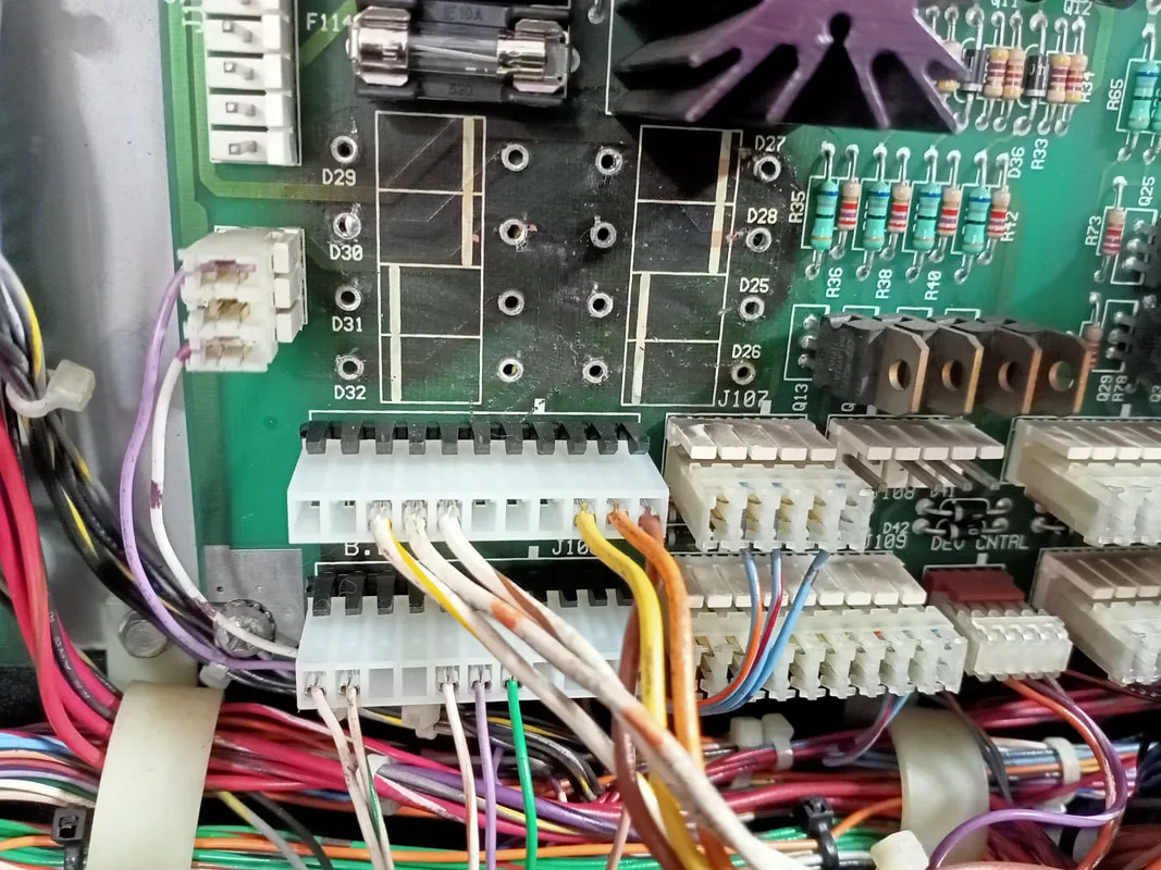
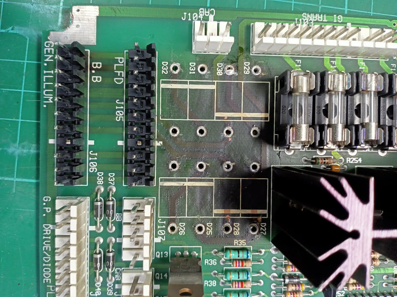
At this point, I thought it was worthwhile removing the power driver board to replace the header pins for J105 and J106, as I had just replaced the connectors and there was no point only replacing half of the connection system. I replaced the header pins, and while I was at it, I also removed the general illumination lamp diodes that are also in this area. This is a recommended upgrade as per Pinwiki. Jumper wires on the back bypassed the (removed) diodes, so this part of the board won't get any more charred than it already is.

Removal of GI diodes and new connectors installed at J105 and J106.
Installation of jumper wires to bypass GI diodes.

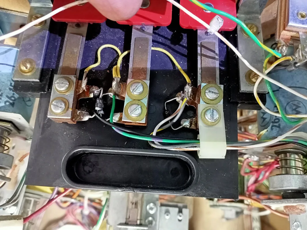
Then the next general illumination problem turned up. The symptom of this problem was a blown F114 fuse, which supplies the white-brown general illumination circuit on J105. According to the lamp table, this circuit services the lower playfield general illumination lamps. It helped to disconnect J105 and J106 one at a time to narrow down the issue to the playfield instead of the backbox.
It took me a while (and a couple of fuses) to finally figure out the problem. The two AC supply wires for this lamp circuit were shorted together at one of the lamp sockets on the lower left of the playfield, near the inlane. This was blowing the fuse. I moved the solder tabs further apart so they were no longer touching, and the problem went away.

Lamp socket with shorted supply wires.
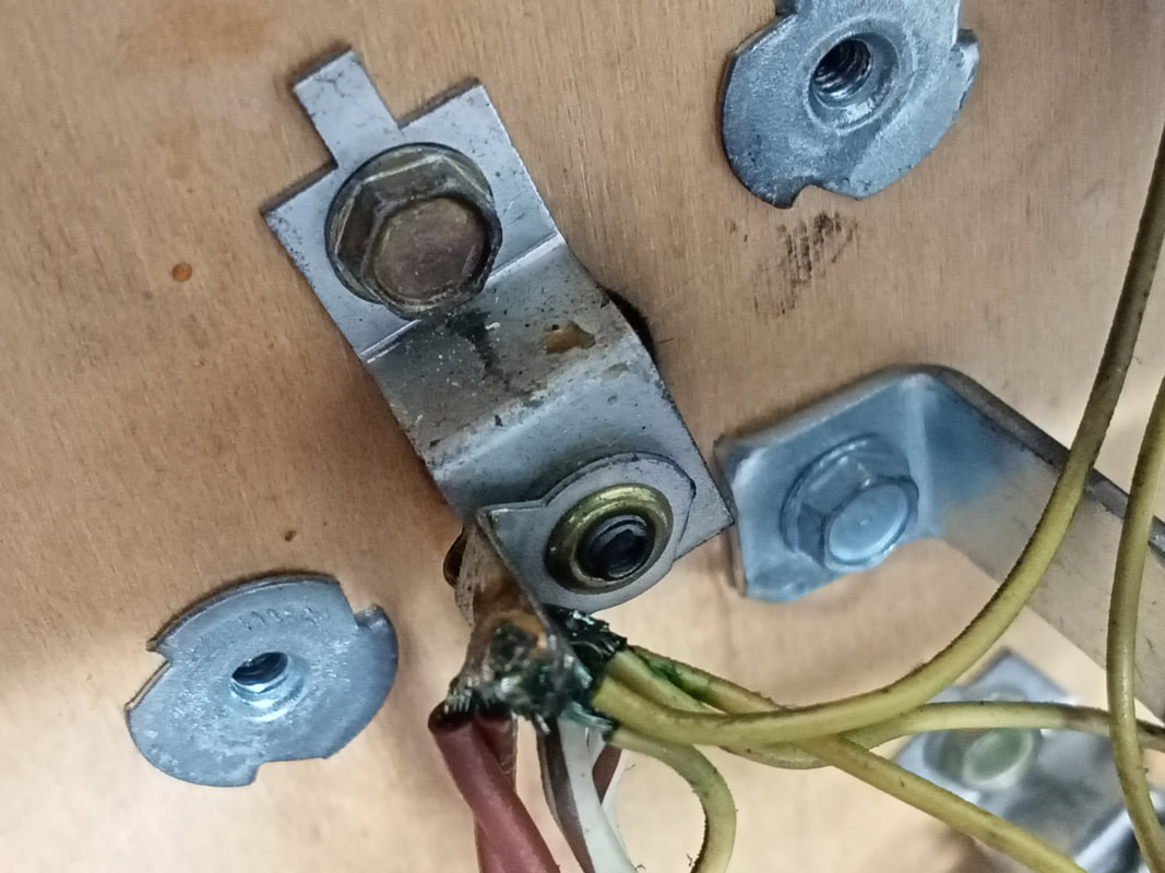
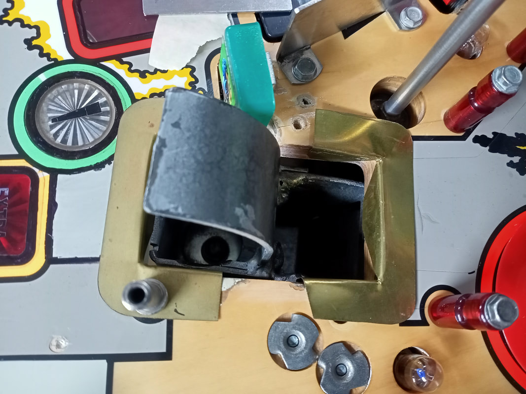
The target assembly comes out of the playfield easily, however it is easier to remove the motor assembly first (four screws) before removing the target assembly (two screws). I found it best to remove the lamp board adjacent to the motor assembly to make things easier.
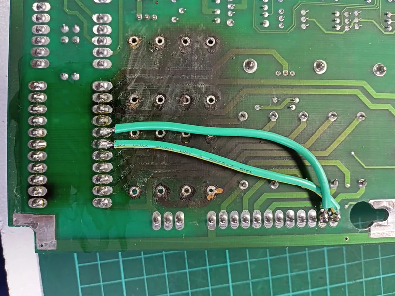
Once the assembly was out, I noticed the problem. None of the switches were actually wired up. A single white-red wire was attached to one of the switches, but that was it. There were no other wires or connectors to actually interface the switches to the game, and the single white-red wire was also broken.

3-bank target assembly after removal. Single, broken white-red wire visible.
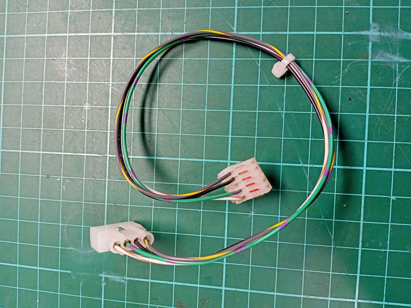
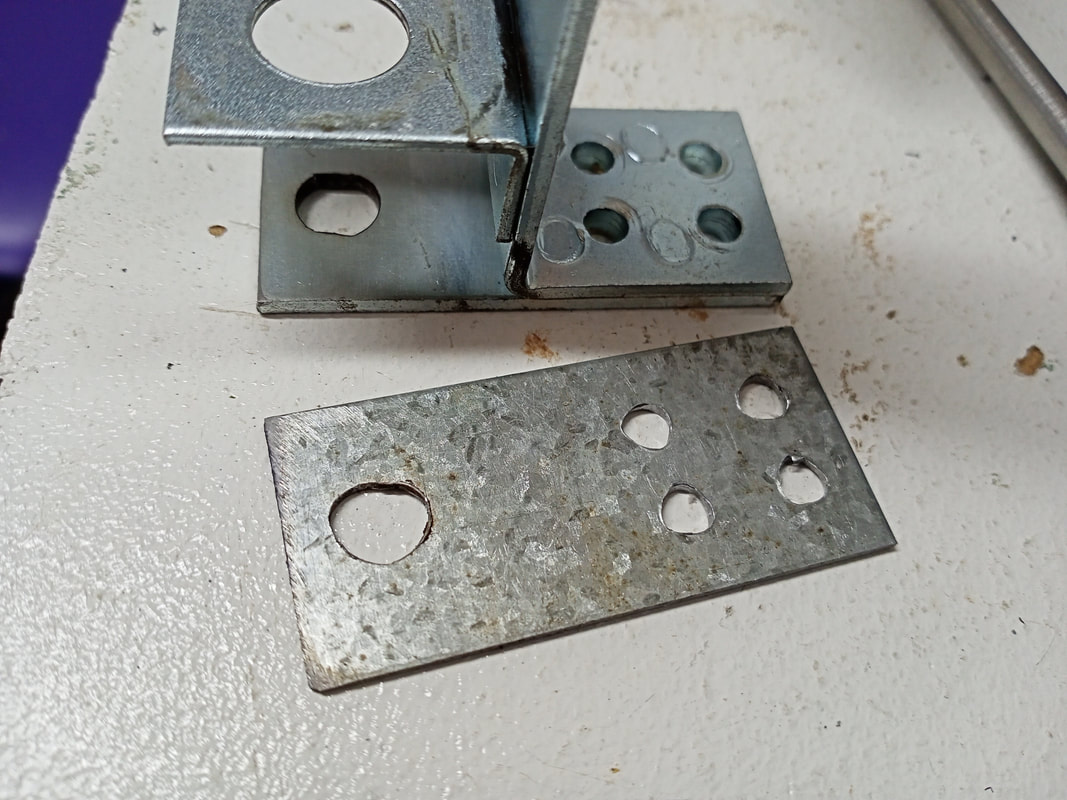
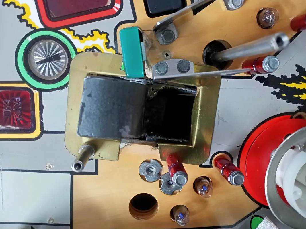
Time to check the switch matrix in the manual. The 3-bank target switches are in the same switch column, which is supplied by a green-yellow wire. This should be connected to all of the switches on the banded side of the diodes. The target switches are connected to three separate rows (white-green, white-blue, white-violet). So the left, centre and right switches should be wired to those, respectively. First, I had a look around the cabinet for a connector that had these wire colours. It didn't take me long to find it, just above and to the left of where the assembly usually sits. This was a four-position connector with all column and row connections needed for the 3-bank. It looked like the wiring harness that connected the targets to this connector had simply vanished. It was not in the boxes of parts I received with the game, and was nowhere to be found in the cabinet.
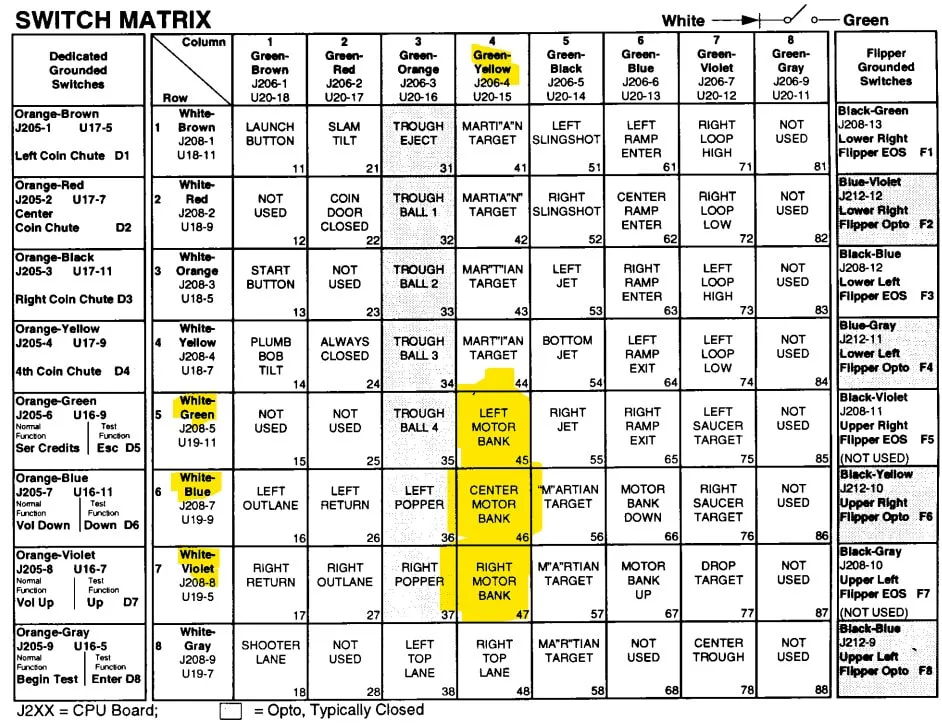
Switch matrix with 3-bank targets highlighted.
Luckily, I had a similar wiring harness in my spare parts. Of course, the wire colours didn't match, but I'll put a label on the harness to indicate that the colours aren't original. If I didn't have a spare harness, it would be easy enough to make some with the wires, a 4-position plug (element14) and pins (element14). All I needed to do was cut off one end of the harness, and solder it to the appropriate switches. I also installed a small wire "C" clip to make sure the wires don't get caught up in the carrier mechanism.

Replacement target switch harness.
3-bank target assembly back in the game and wired up.
At this point, the switches were working again and registering correctly. Yay!

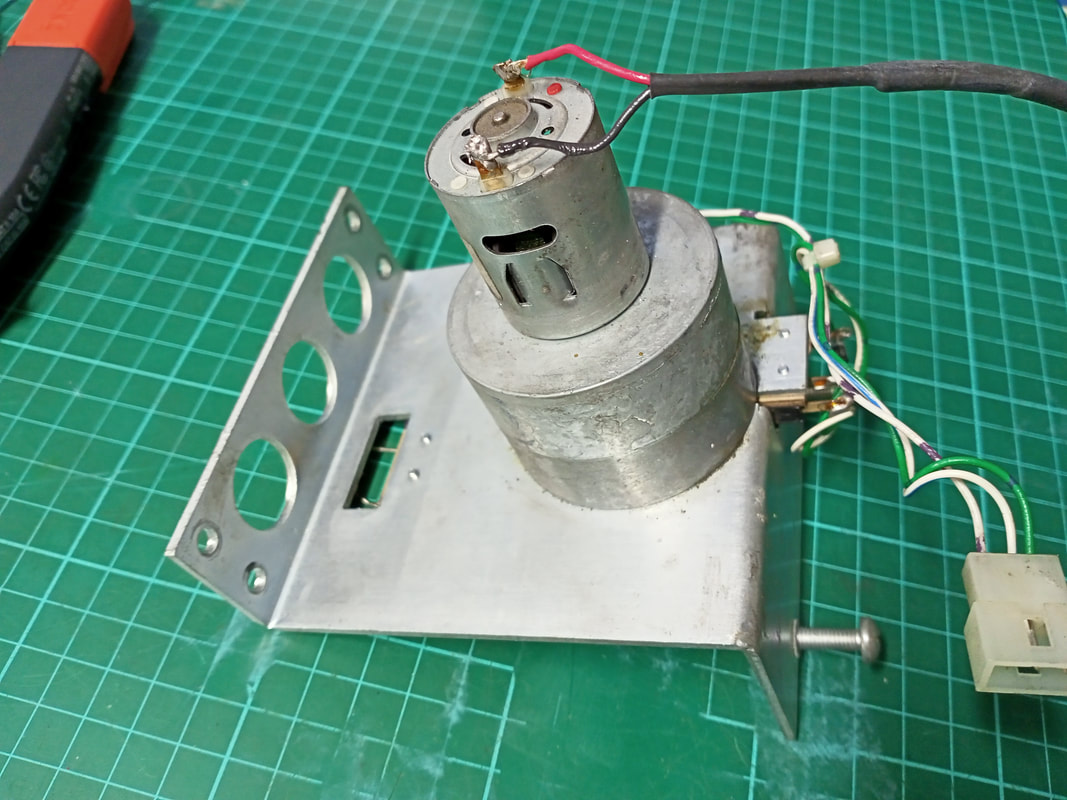
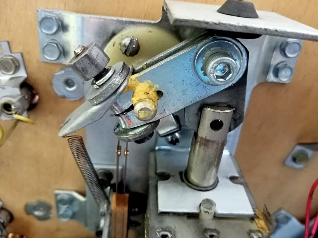
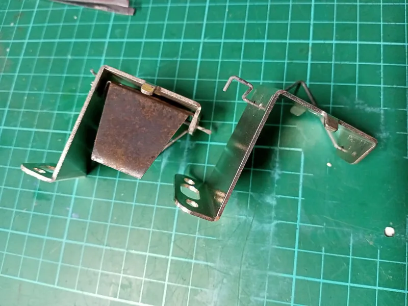
Motor assembly including mounting bracket, motor and gearbox after removal.
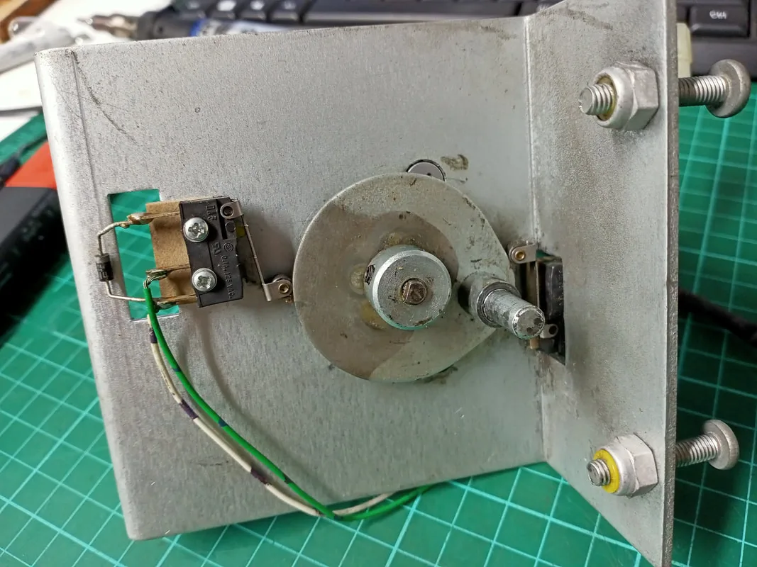
Lifting cam and up and down position switches on the mounting bracket.

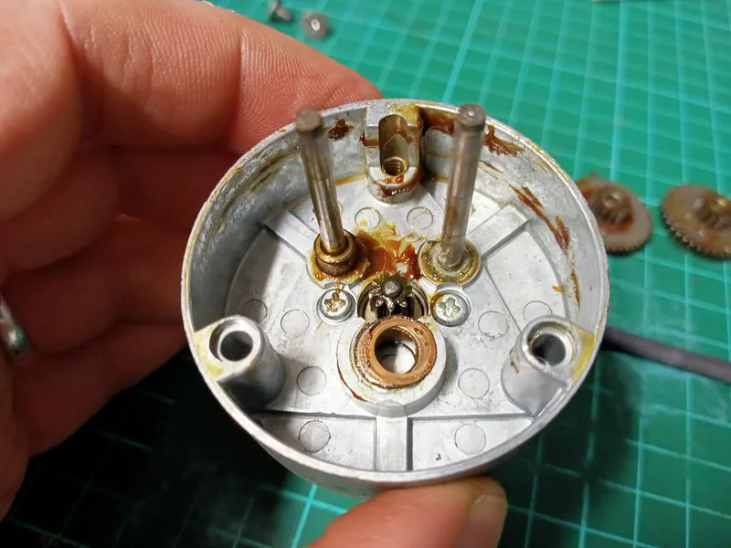
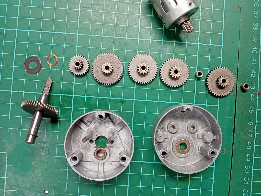
I already had the motor assembly out, so I hooked up the motor to a 12VDC power supply. No dice. I could see the motor engage as it if it was trying to spin, but there was no actual movement. I couldn't move the lift cam manually, either. So, time to do some gearbox servicing! Getting to the gearbox is a breeze on this game. Remove the lift cam (grub screw), unbolt the gearbox from the mounting bracket (two screws), and undo the screws that secure the gearbox casing (three screws). That's it! You're in! The gallery of photos below show the stages of disassembly and the positions of the gears.
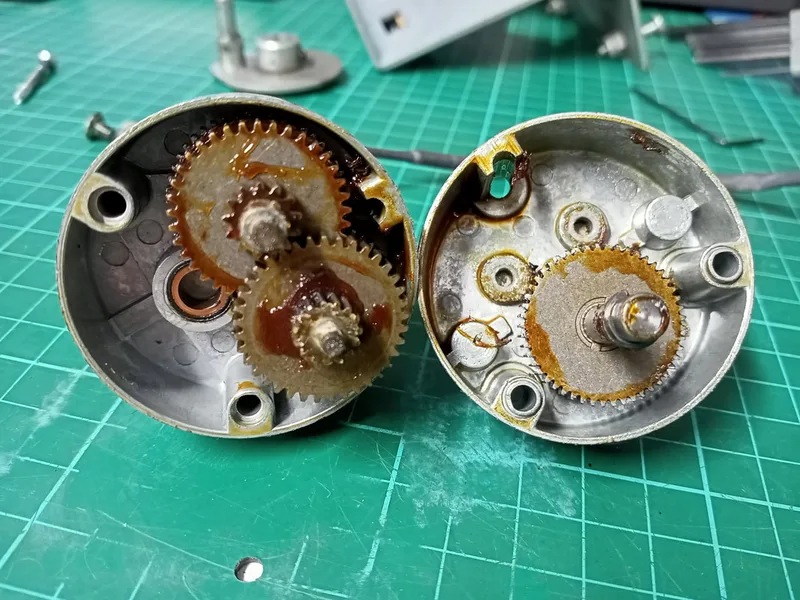
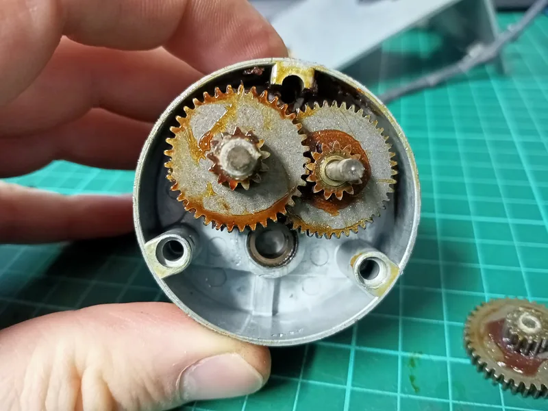
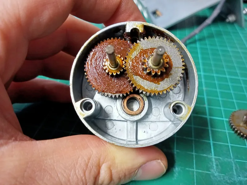
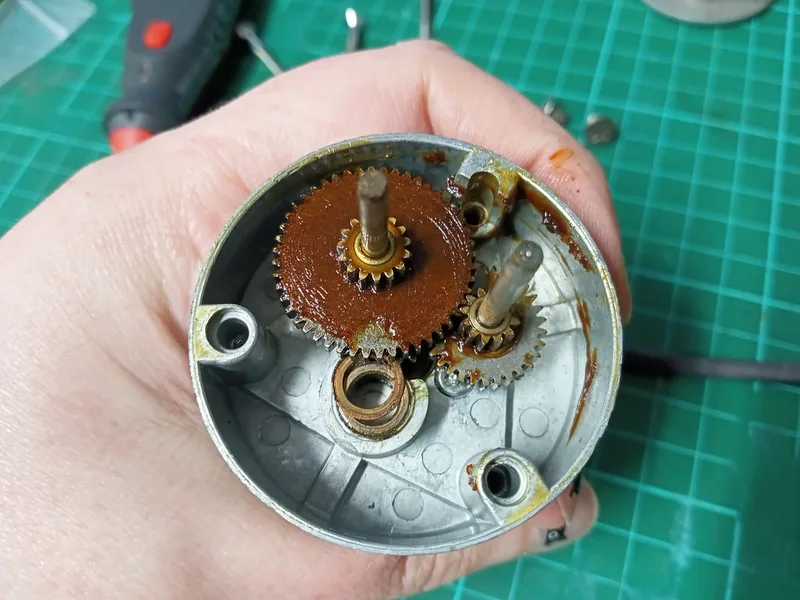
Once I started taking the gears apart, it became evident that the old grease had gummed up and solidified. None of the gears were able to move. Once of the spacers exemplified this well; the grease had solidified into a thick layer that came off it in one piece.

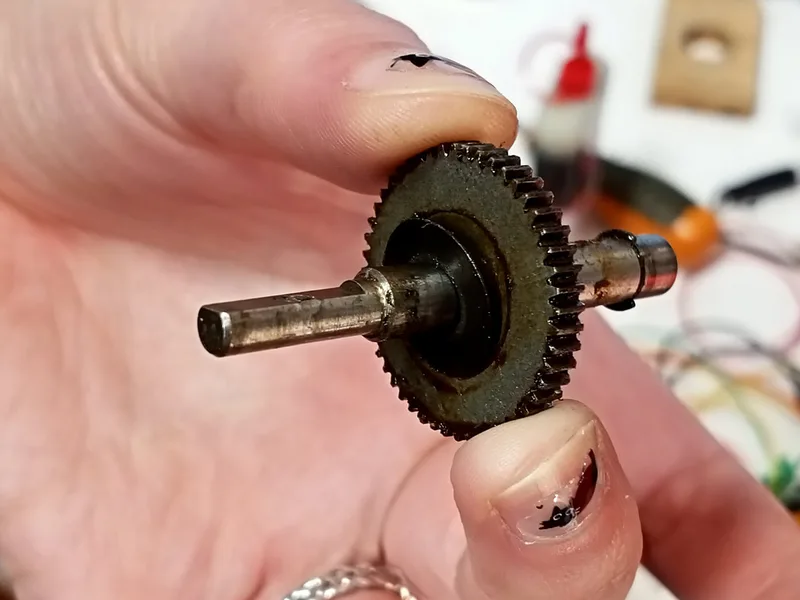
Solidified grease on one of the spacers.
Once I got down to the base of the gearbox, I could undo the two screws that held the motor in place. With the motor free from the gearbox, I could test it again with my power supply and verified that it did indeed work. So, the problem was definitely the gears. Then came the job of degreasing and cleaning each of the gears and spacers until they were nice and shiny. Then, a new coat of grease over everything to lube it up again. Once it was back together, I hooked it up to my 12V supply again and the whole thing came to life. We had movement! I reinstalled everything into the assembly, and mated it with the moving target bank. The bank now moved up and down like it should. Motor repair success!
Cleaned gearbox and gears.
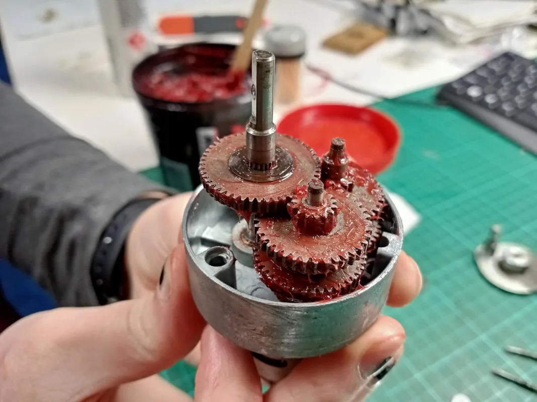
All lubed up and ready to go!

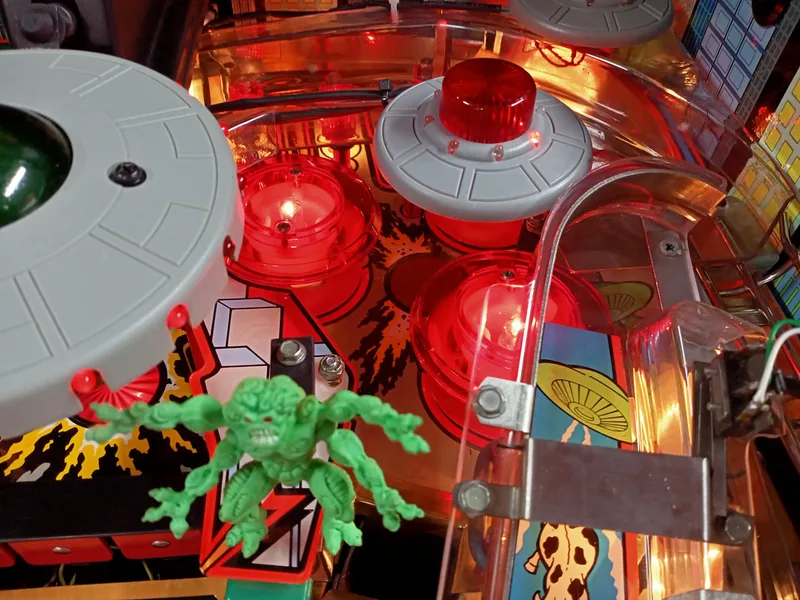
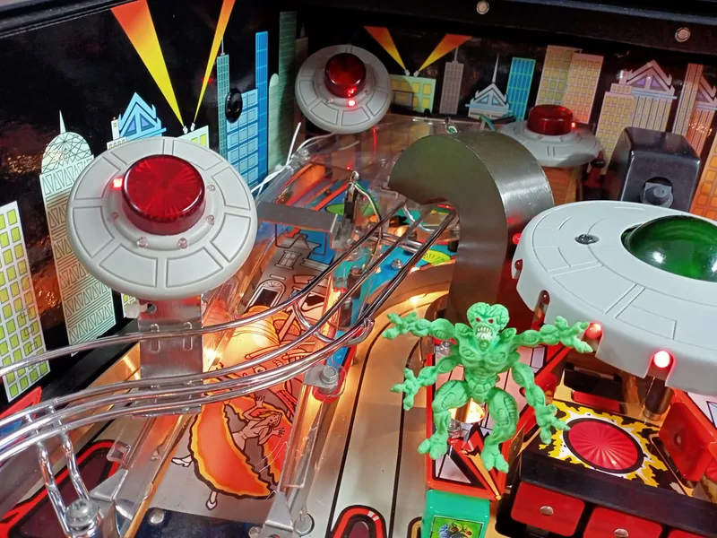
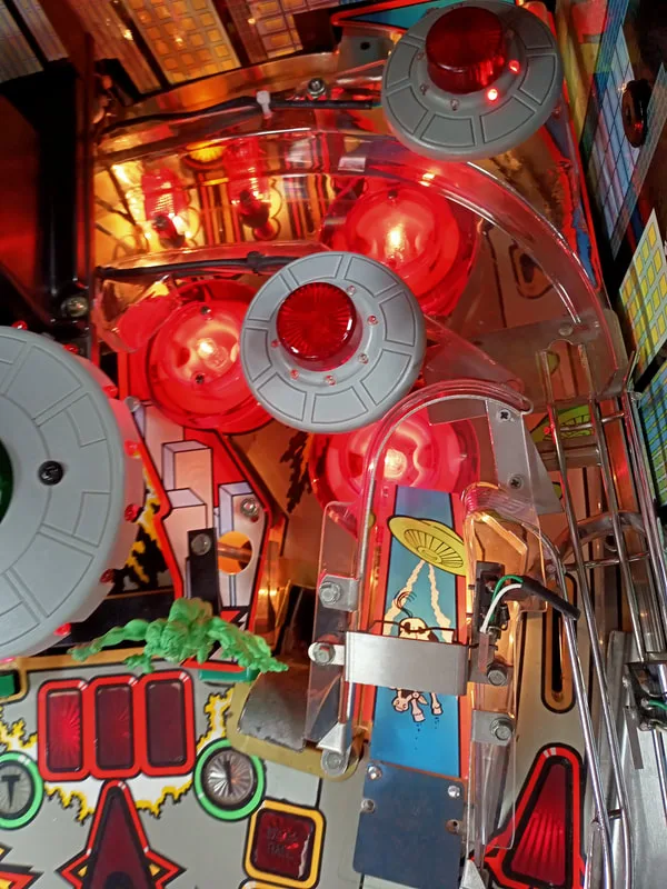
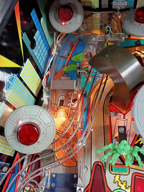
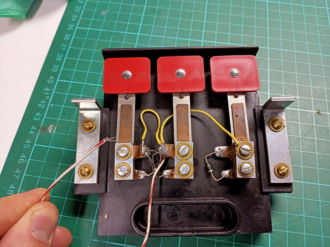
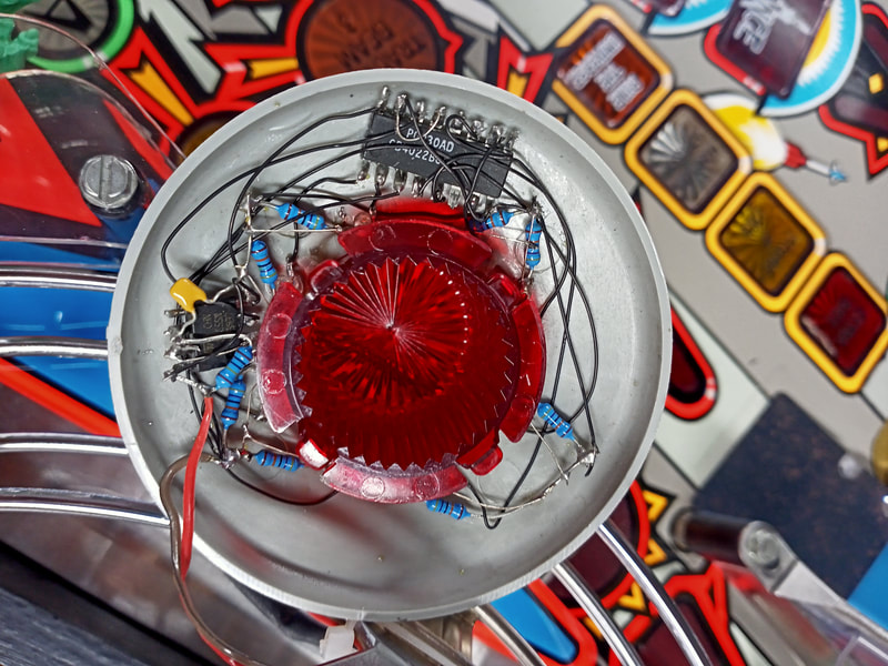
This game had the "Temu version" of the saucer LED mod. I spent a couple of hours studying how it worked and wiring it back up correctly so that it would operate properly, as it was missing power cables and had some wires broken when I first got the game. Like the Bill Ung version, each saucer on the playfield has an array of LEDs installed in the mould holes around the flasher dome. However, with this mod, the LEDs are connected to a 555 timer and a CD4022 octal counter integrated circuit mounted under each saucer. The basic design of the circuitry associated with each saucer is described here. It's a simple circuit which pulses each LED in sequence, like a chase light. It's a cool effect, although the implementation (i.e. how it is installed under the saucers) is a bit haphazard.

A view of the LED chase light circuitry.
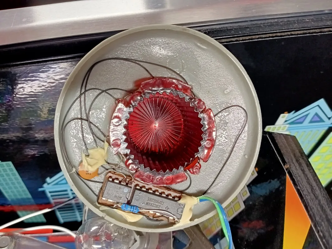
Circuitry under another saucer with a neater installation.

Each of the saucers are connected to power via an RCA cable. In fact, any simple wiring method with at least two conductors will work for this mod. I found one of the saucer wires had been cut, probably so the ramp the saucer was on could be removed from the game. I installed a connector on it to make removal easier in future. I also had to resolder a couple of wires and LEDs within a couple of the saucers, as the wires are very thin and fragile. Once I got this done, each of the saucers was getting power and the LEDs were lighting up as they should. I did need to buy an additional 2-in-1 RCA cable (Jaycar) as I was one power supply socket short.
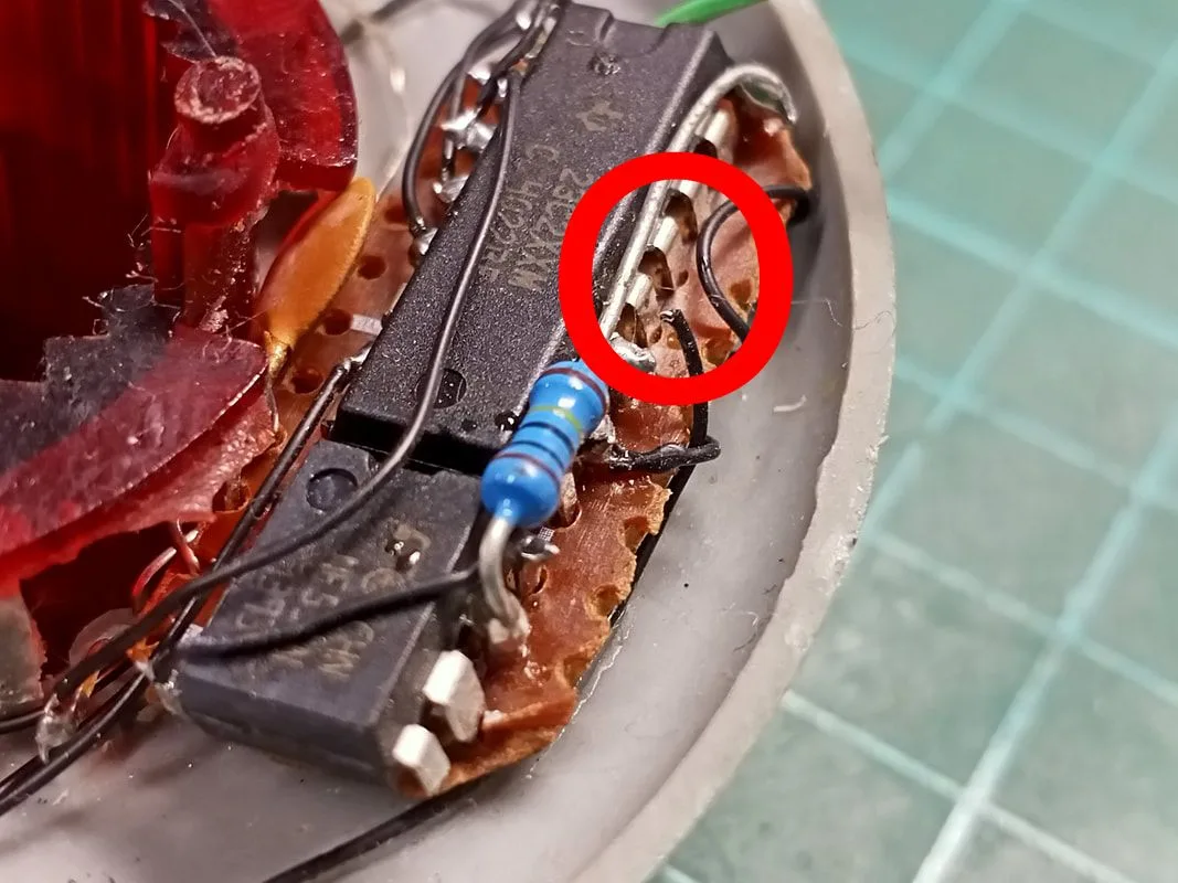
Broken wire on one of the saucers.


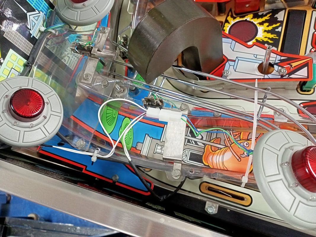
New connector installed to supply power to saucers on the left ramp.
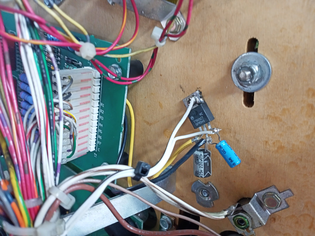
The RCA cables are all supplied power via an MCT7805 5-volt voltage regulator, which was soldered to the nearby opto board under the playfield. This supplies the regulator with a 12-volt input voltage and ground. Each saucer is then simply connected to the regulator output and ground, with the saucers being daisy-chained together.
Voltage regulator that supplies the saucer LEDs.
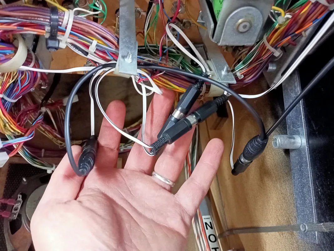
RCA cables used to supply power to the saucer LEDs.

Catastrophic flipper bat failure.
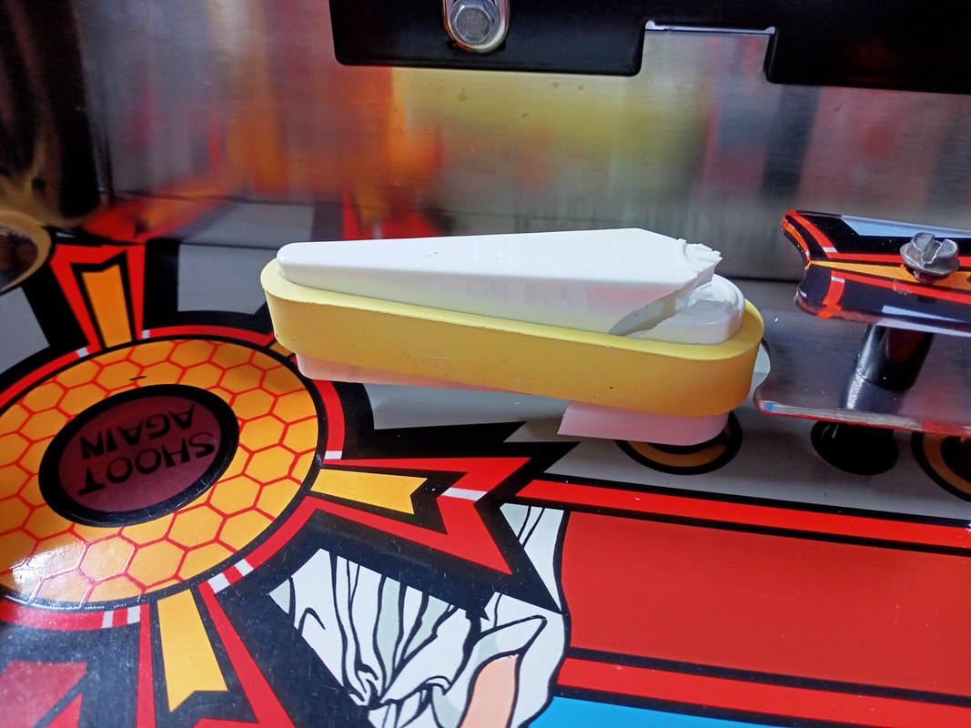
Use of glue to secure the flipper bat in the crank assembly; not cool!

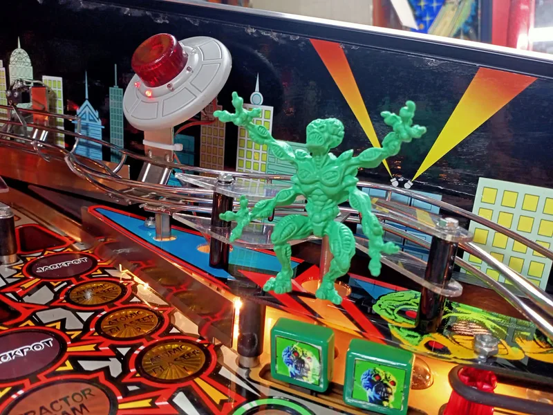
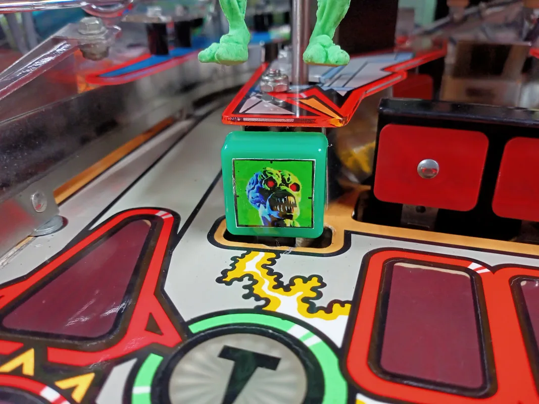
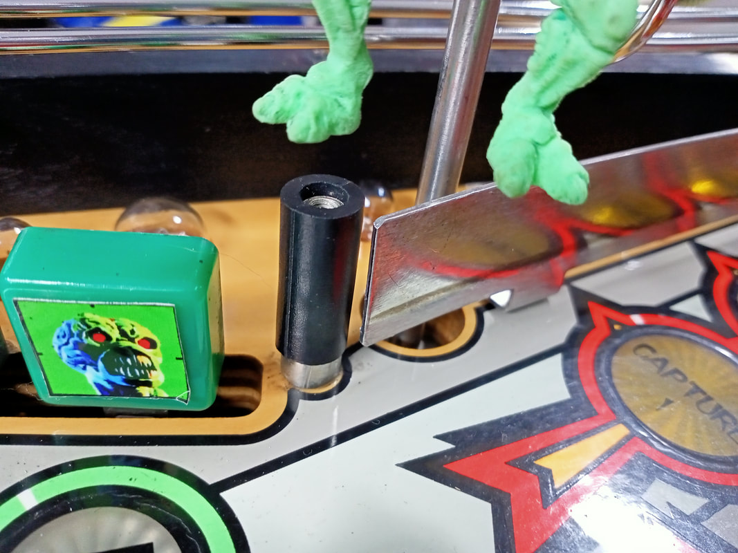
I posit that the FL-11629 coils used here are actually a little too strong. They send the balls into the "T" and "I" martian targets at high speeds which cause the balls to deflect off the targets and go airborne. A cool effect, to be sure, but I can see why these targets, and the Stroke of Luck scoop, are commonly broken on these games.
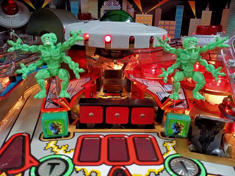
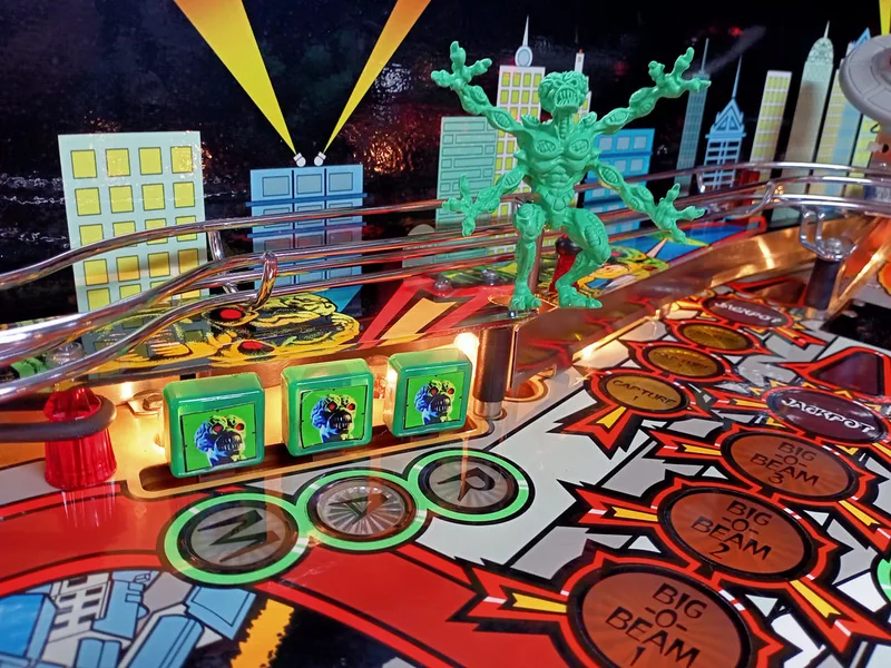
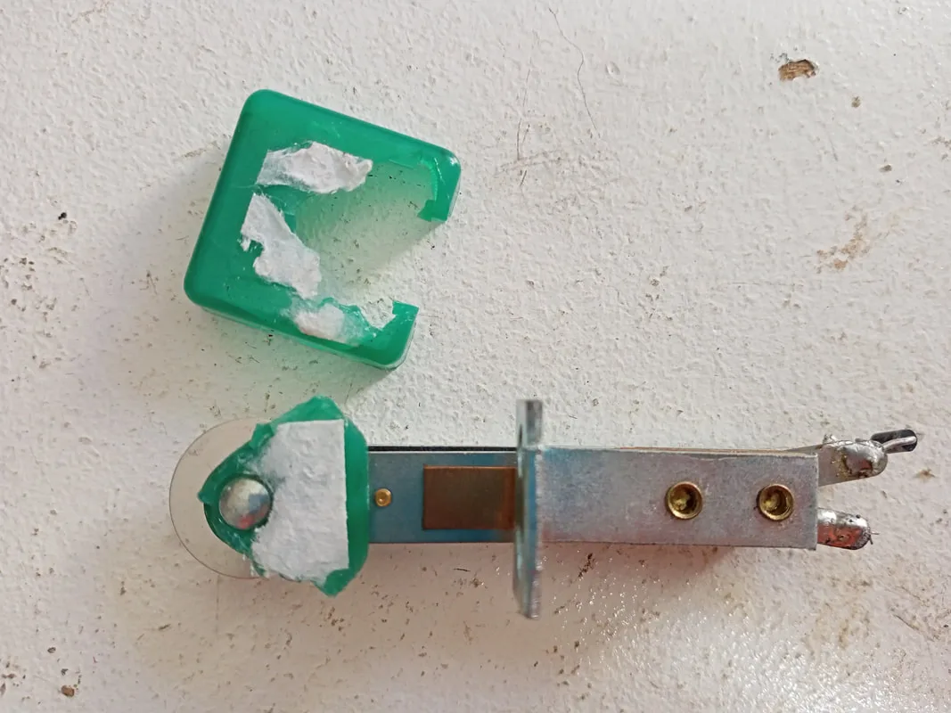
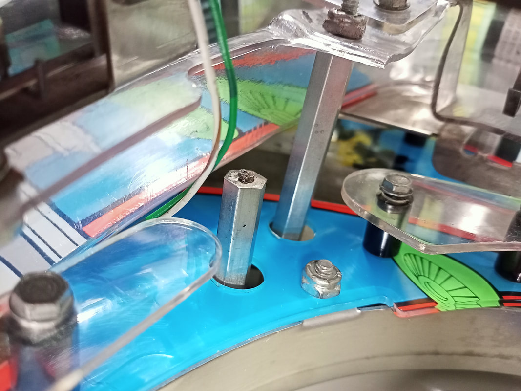
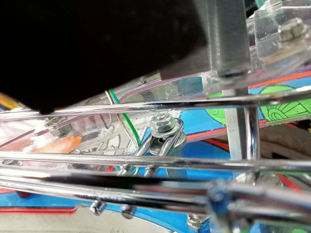
While the jumping around is cool, there was a problem. The martian on the left side of the playfield was actually spinning around on the shaft when jumping around, such that he would turn into the wireform ramp and block the balls. The martians are not supposed to spin around like this; they are meant to be locked in place so they only move vertically up and down, but stay facing the one direction. The assembly is constructed such that the martians are mounted to a long shaft that is kept in place by the main mounting bracket/weldment. This weldment has a notched hole while the shaft sits in. The shaft is also notched, so that it cannot "spin" in the hole. However, over the course of many years, the shaft wears out the hole in the weldment, making it wider. This provides enough space for the shaft to rotate, as the notch is basically worn away. So, the shaft will spin, and the martian will spin with it.
One solution is to buy a new bracket/weldment (PSPA). However I decided on a simpler solution. I cut some sheet metal to the same size as the topside of the weldment. This new piece would sit between the weldment and the underside of the playfield. Then, I cut a new hole in the piece which matched the size and notch arrangement of the shaft. In effect, I was replacing the worn out hole in the weldment. After some test fitting and drilling new holes for the mounting screws, it was done. I had to make up three plates in total, as three of the martian assemblies were spinning around. Once the new plates were in, they stopped spinning around. Similar pre-fabricated plates are also available on eBay.

View of the martian weldment assembly, showing the worn out hole which the plunger rubs up against.
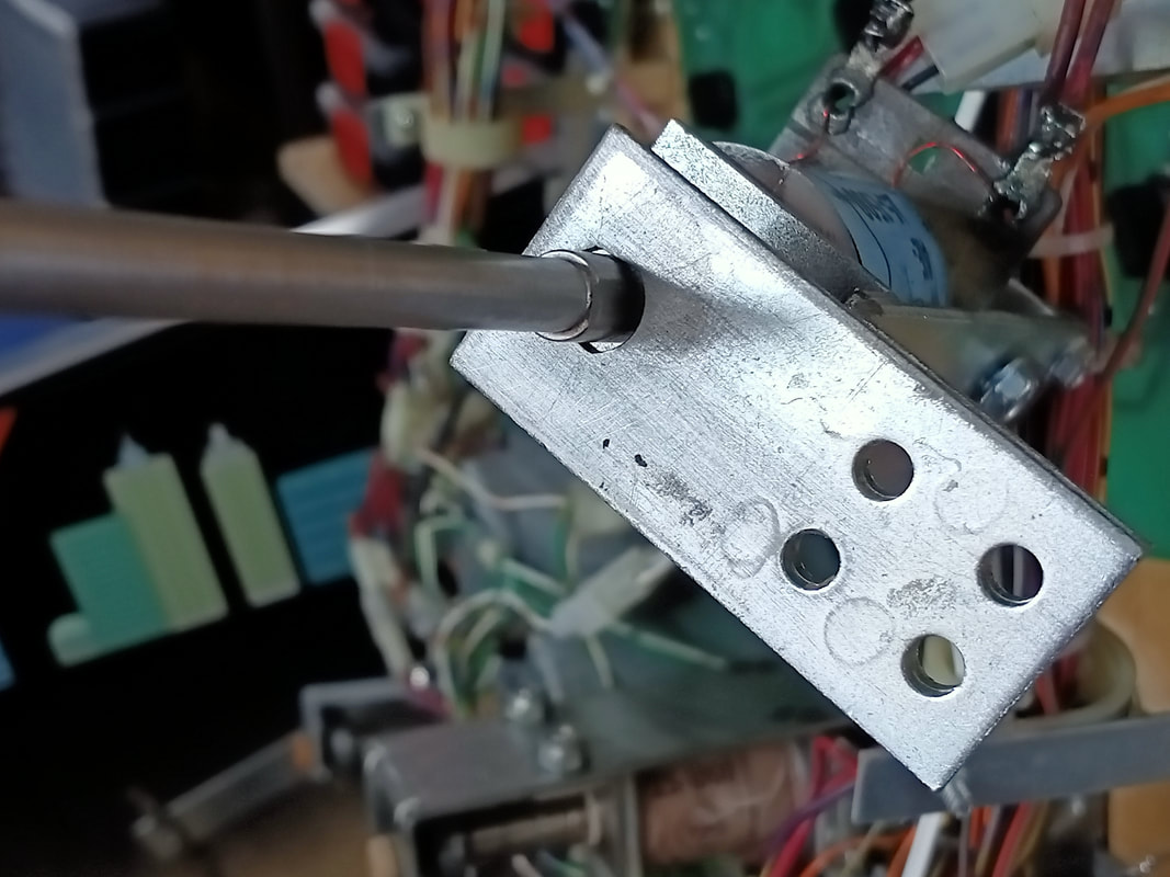
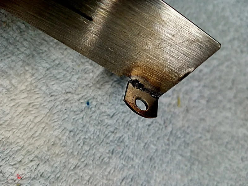
Plate fabricated to lock the martian plunger in place.
Broken "T" target face.
New "T" switch installed and decal reapplied.


Broken spacer thread.

New spacer installed with new thread.
What causes this spacer to break? I think the coil in the left popper is way too strong, because it kicks out balls with enough force onto the wireform ramp that the whole playfield shakes. This much force has to go somewhere, and the thread on this spacer happens to be the closest anchor point that absorbs the brunt of the force.
Complete gate assembly on the left, and gate assembly missing the flap on the right.
The only difference between the left and right gate assemblies is the position of the flap, and the shape of the gate wire. The flap and wire can be swapped around to turn a left-hand gate into a right-hand gate. Parts to do this are available, including the flap (Mr Pinball), left gate (PSPA, Mr Pinball), right gate (PSPA, Mr Pinball), and swaged hinge wire (PSPA, Mr Pinball). I bought all of these parts, installed the missing parts, and the gates were operational again.

Complete gate assemblies reinstalled into the game.
First, taking out the trough to have a good look at it revealed the first potential problem. The switch slot had been dented by thousands of balls hitting it over the years, creating a bit of a divot. The ball would then sit in this divot, and couldn't get out. A hammer and punch tool to bash the divot back to a flat plane solved this problem.
Divot beaten into the switch slot of the centre trough.

But the issue remained, and the ball kept getting stuck in the switch slot of the trough. Further investigation revealed that the rollover switch actuator was not being depressed by the ball, and it was "holding" the ball in place if it dropped into the trough at a certain angle. The bend in the actuator creates a high point, which the ball can get stuck behind. Because the switch is mounted leftwards, rather than rightwards, simple gravity and momentum was not enough for the ball to roll over the switch. It needed an extra push to overcome the natural resistance of the switch mechanism (which is minimal at the best of times).
Switch mounting position and actuator shape. The apex of the actuator is too far to the right.

Ultimately, this switch mounting bracket is poorly placed, and the switch actuator is the wrong shape. I had to flatten out the switch actuator so that it covered more of the switch slot, which meant that balls would fall on top of it and close the switch more easily by falling into the trough. It's much easier for gravity to do all of the switch closing work here, compared to the minor force of a rolling ball.
Switch actuator after bending to a more reliable shape.
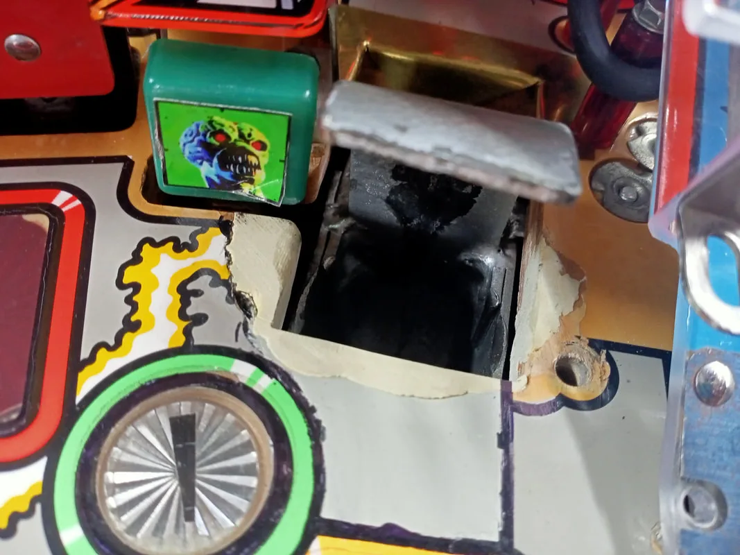
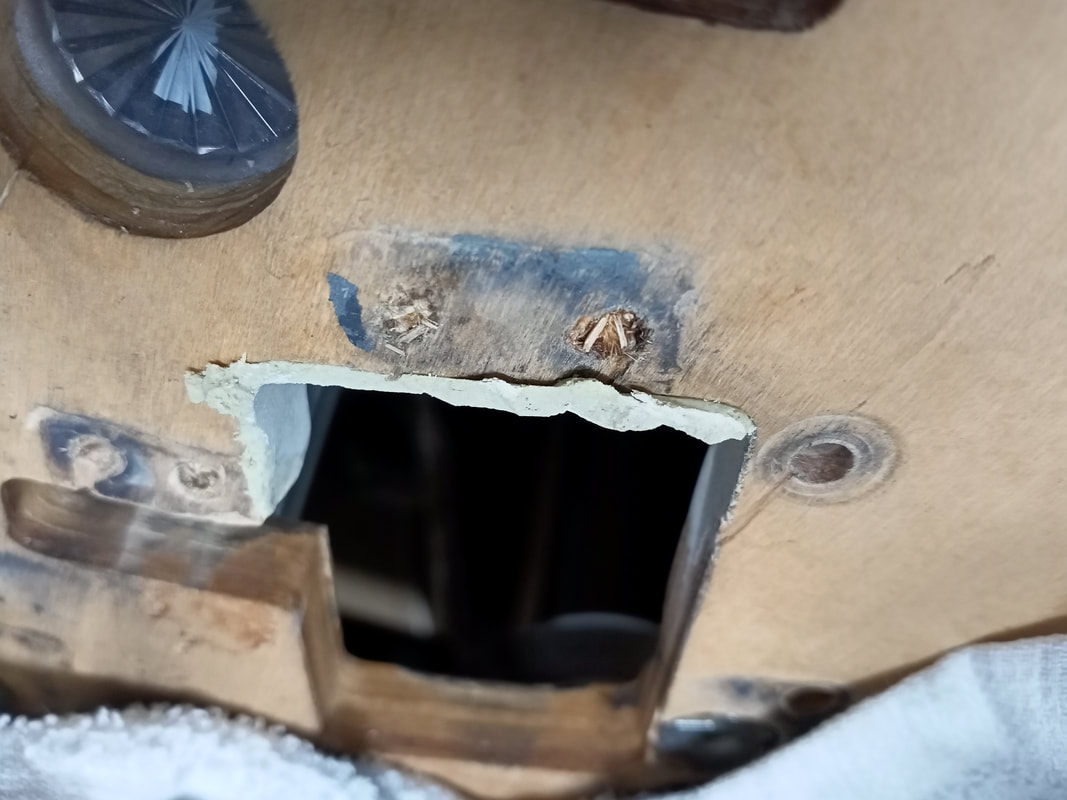
Stroke of Luck hole; topside after timber repair.

Stroke of Luck hole; underside after timber repair.
After some initial fiddling around with proper positioning and some bends and adjustments to the protectors, they were ready to fit. There was a hole cut into the front protector already, but I needed to add some holes to the rear protector which covered up a couple of mounting holes for a ball guide and a post.

Protectors checked for fitment.
Holes cut and posts installed. Note the screw for the leftmost red plastic post is shorter than normal.
Once they were installed, they covered up the damaged areas reasonably well. A quick and cost effective alternative to brand-name protectors!
I needed to adjust the metal ball guide on the left side of the playfield a little. Balls coming down this orbit would strike the rubber post, which sent them straight down the middle. The ball guide needed to be bent towards the centre of the playfield to keep the ball away from the post. Some pliers and protective matting let me bend the guide without damaging it.
Ball guide which needed adjustment so balls wouldn't hit the rubber post.
One additional ball guide repair was needed. The mounting tab for the ball guide closest to the shooter lane had broken off. The autoplunger coil bracket was misaligned, which meant balls were being fired to the left side of the shooter lane instead of straight up it. The ball guide was taking most of this force, which eventually snapped the mounting tab off. A few small welds got it back together again.
Ball guide mounting tab after repair.

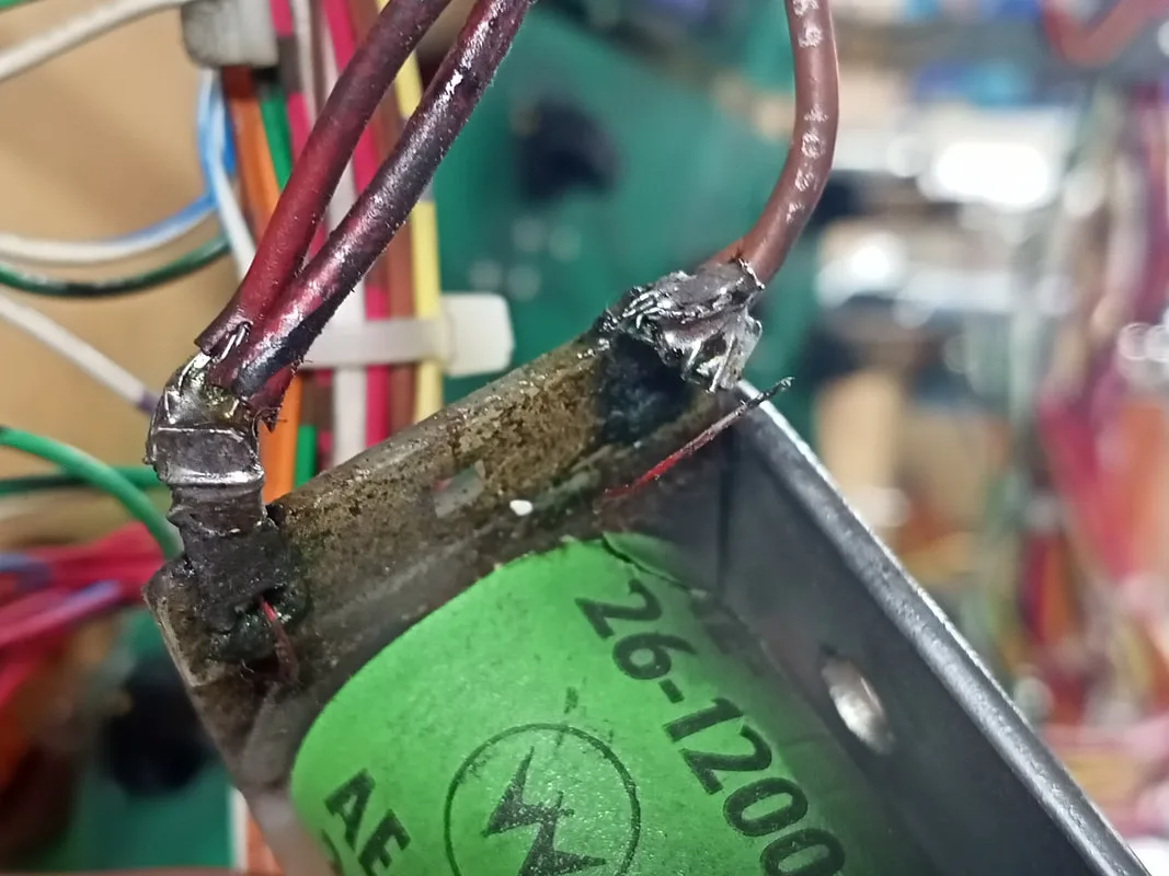
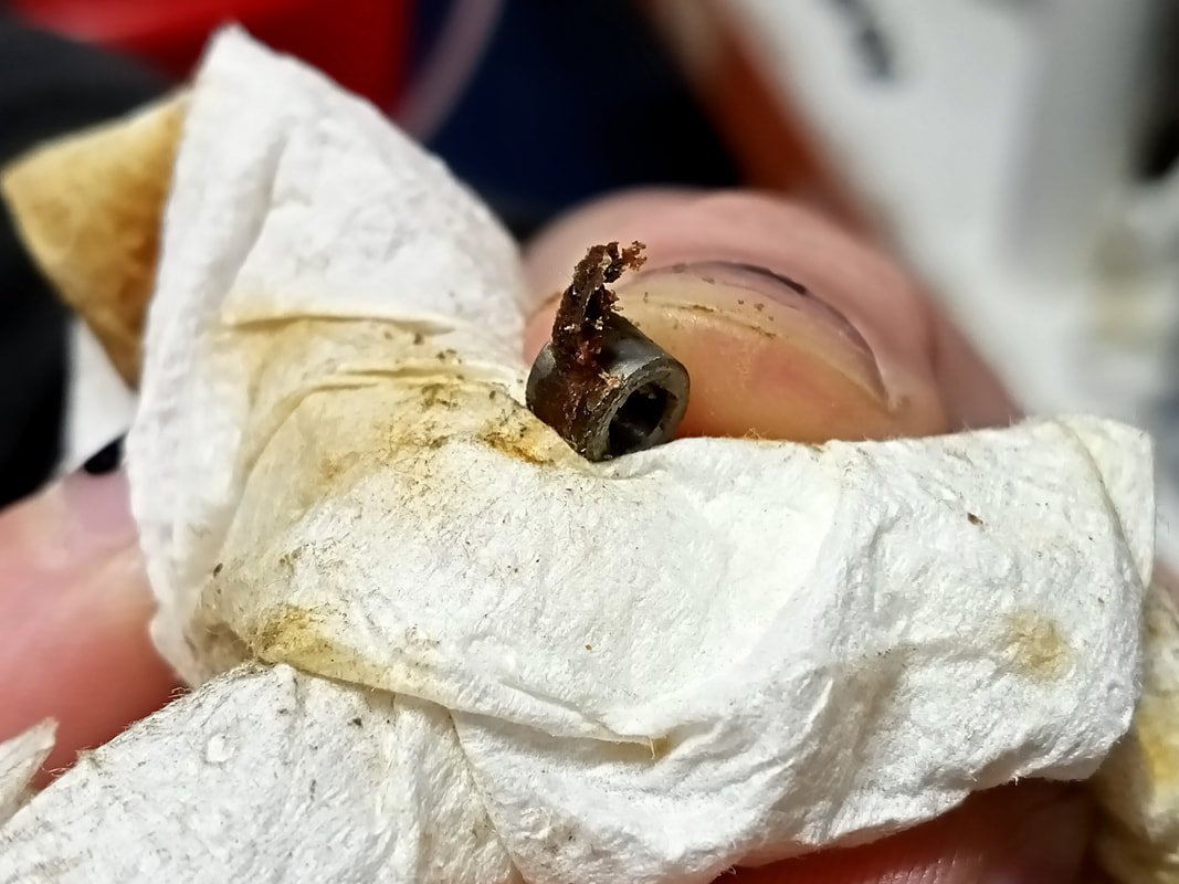
Coil winding detached from lug.
Coil winding reattached.
This was caused by divots in the metal trough trapping the balls and preventing them from rolling down the assembly as they should naturally be inclined to do. A simple, effective solution to this, short of purchasing a brand new trough assembly (RTBB, Mr Pinball, Pinball Haus), is to purchase a shim (RTBB, PSPA, Pinball Haus) which slides into the trough and sits below the balls, creating a smooth, even surface that helps the balls roll down towards the trough coil. This solved the ball hang-ups in my case.
Ball trough shim installed.

As this game had been disassembled before I go it, reassembly was interesting because I had to reply on my own knowledge about how Williams and Bally playfields were constructed to put it back together. I found some detailed teardown pictures which also helped the process.
I noticed one main issue with the way the game was put together that needed rectification. The backbox lamp insert panel was a little odd. It connected to the lamp connector on the right side, whereas most games connect to it on the left side. Also, the positions of the lamps seemed a little "strange". The flashers, in particular, were not where they were supposed to be. Several flashers are meant to light up the explosion on the bottom right of the backglass, but these were not present at all.
Turns out, this lamp insert panel was actually installed upside-down. Someone had replaced the plastic trim on the edges, and had put the panel back on incorrectly. Flipping it upside-down put the flashers back into their correct positions relative to the imagery on the backglass, and also put the connector on the correct (left) side of the game. This post on Pinside helped me figure out that mine was the wrong way around.
Backblox lamp insert installed upside-down.
Conclusion
Attack from Mars is always at the top of most peoples' most wanted pinball lists, and I can see why. It's a damn fun game. Destroying saucers is one of the most fun things to do in a pinball machine, and the saucer is one of the best integrated toys in pinball machines of the 1990s. Plus, the jumping martians are a lot of fun (particularly when they're not spinning around and blocking the balls!). This is a very quick and deadly game. Shots to the centre bank or the martian targets send the ball straight back to the flippers. Ramp and orbit shots are fast and mean. A good game for fast thinking players, and those who like to "run and gun".
However, it's not a particularly deep game, and after a while the game can feel a little like chopping wood due to the repetition of certain shots. The 3-bank targets and the saucer are the only real shots you need to make to get to the end of the game, so it's probably not a good game to have in a small collection. But it's the perfect game to just pick-up and play, particularly when you don't want to spend a lot of time progressing through modes and navigating a deep ruleset.
The customer was very happy with the finished product, not least because he could finally play one of his favourite game after ten years of it sitting idle in his house in pieces!