- Published on
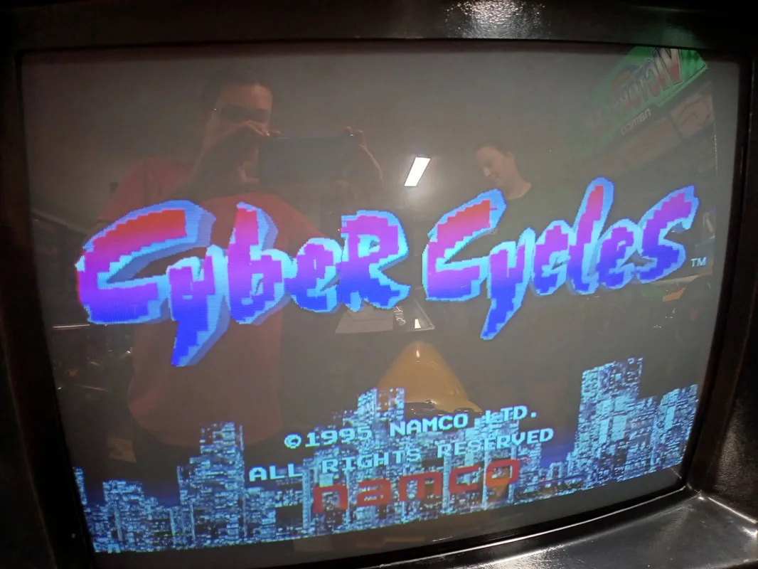
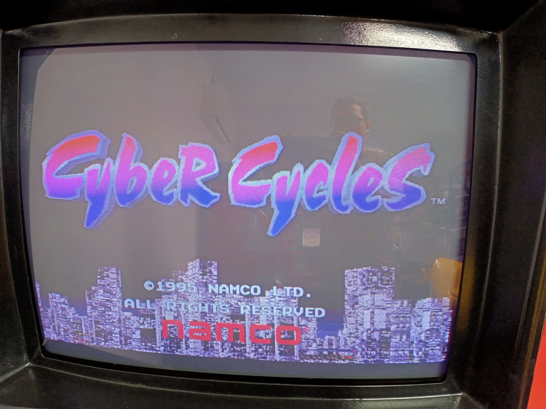
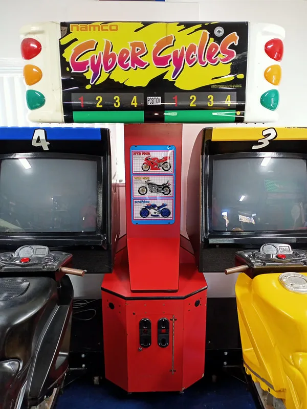
Cyber Cycles
- Author
-
-
- Name
- Posts
- Posts
-
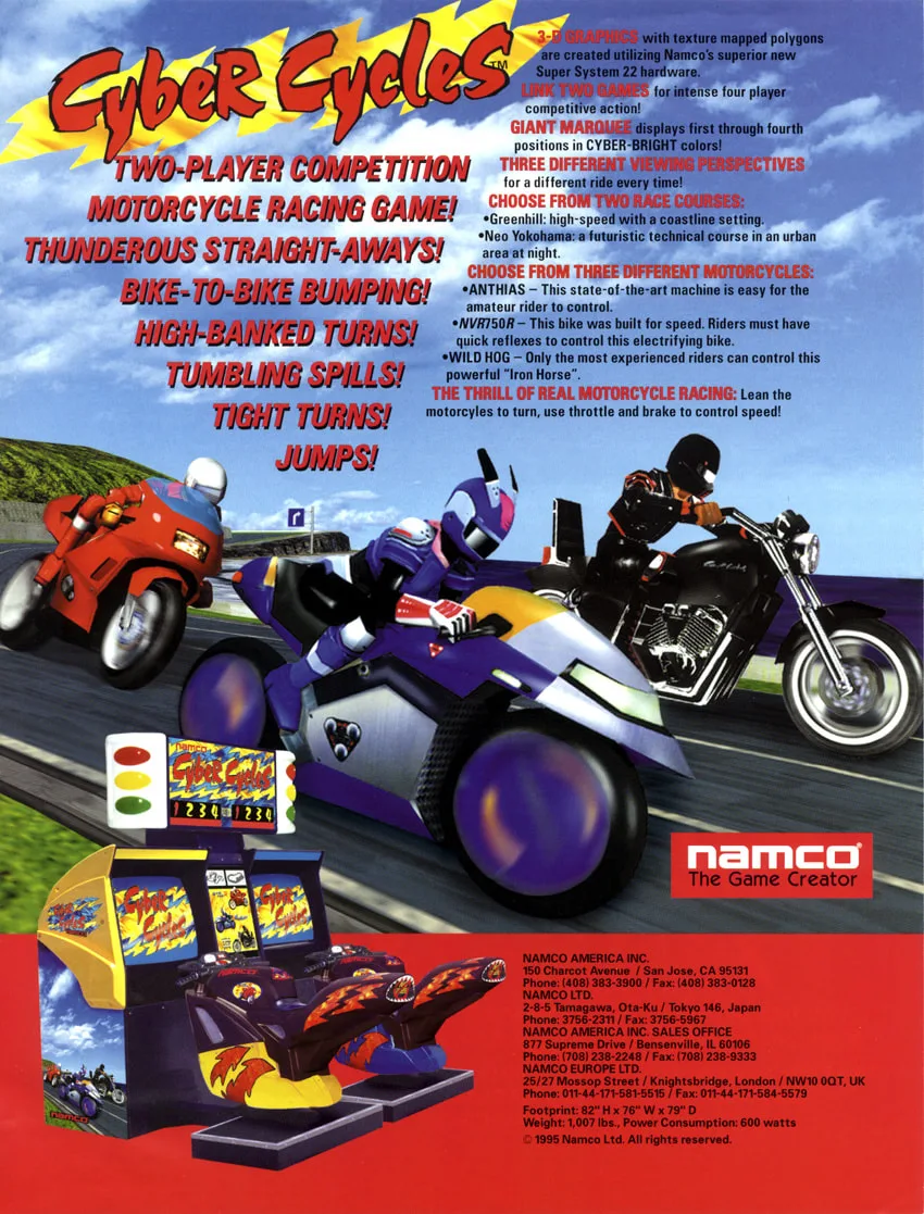
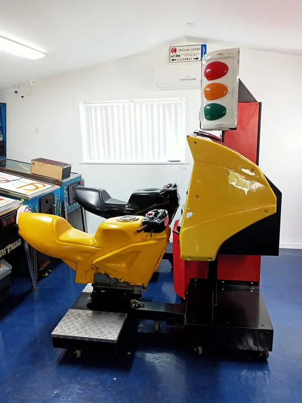
It's not often I work on arcade machines, but after grabbing this Cyber Cylces (Namco, 1995) as a part of a bulk arcade machine deal, I found that it was in need of a fair bit of work. So, I figured this blog post would be a good way to record the journey of learning about this game and board system. The pinball purists will have to forgive me, but even though I am a pinball die hard I still have a soft spot for video arcade games, particularly driving cabs. Cyber Cycles runs on Namco's Super System 22 hardware system, which I would say is a difficult system to repair due to a lack of schematics and general repair information. However, if I decided to sell this game, it would need to be in good working condition for the next owner, so I figure that posting some of my successes (and failures) during this repair may help out other Cyber Cycles owners in the future. Jump on, and let's ride...
Initial condition report (click on sections below to view details)
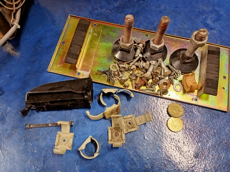
- One side of main cabinet tower was not attached.
- Various cabinet nuts and bolts missing.
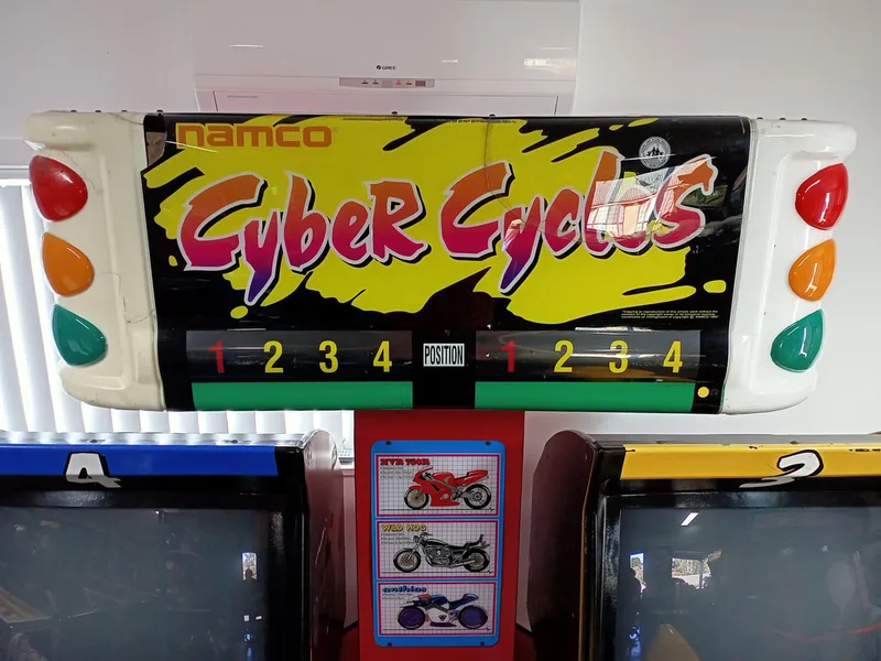
- Topper had multiple cracks.
- Motorbike controllers with various missing parts.
- Plastic surrounds on monitor stands had multiple cracks.
- One motorbike controller was full of rubbish.
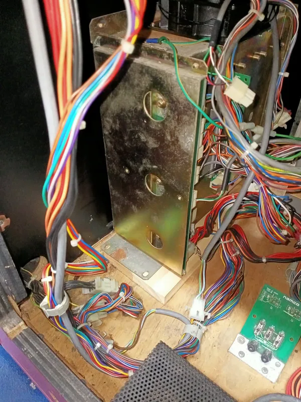
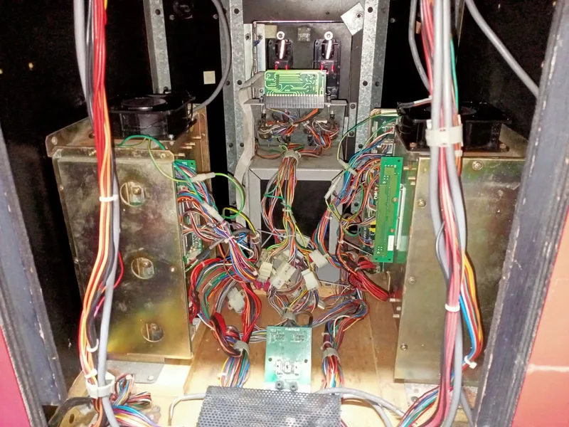
- Circuit board stacks were not securely mounted.
- Most cable management devices/holders were broken.
- One monitor chassis was not securely mounted.
- Wiring throughout the cabinet was a mess.
- One speaker not working.
- Some lights in topper not working.
- Various circuit board issues relating to display, sound, and switch logic.
- Coin mechanisms not registering coins properly.
This machine was going to need a lot of work. And, unfortunately for me, this was my first foray into Namco cabinets. So, what better way to learn more about them than to dive right in? After an initial check of the cabinet interior and monitor chassis for major issues, I found that most of the connectors for each game board set had been disconnected. Luckily, it was easy to tell where they went based on how they were keyed, and the two board sets mirror each other, so I could cross-reference each connector. Once everything was plugged back in, the game came to life, but only one side was working. The game booted into attract mode on the left side only. The right side stayed blank. I couldn't really tell whether it had booted as there was no sound coming from the speakers, and as the coin mechanisms weren't functioning properly, I couldn't coin the game up and start it.
I decided that, with one side working, I could at least swap boards and other components around to test what was and was not working. This is always a good starting point with any twin driving (or shooting) game, as it allows you to troubleshoot using the process of elimination to narrow down the cause of specific issues to a single circuit board, controller, switch, or other component.
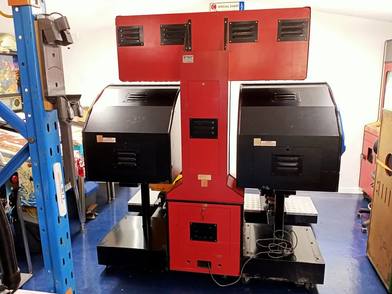
Disassembly
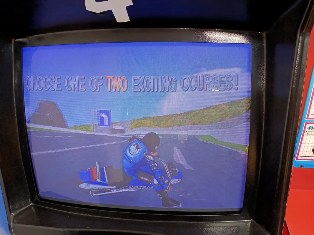
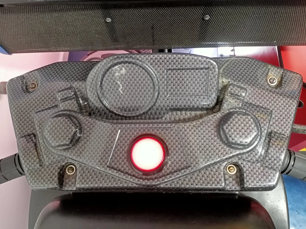
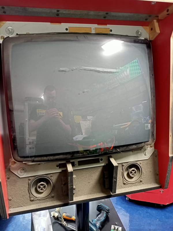
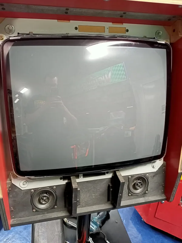
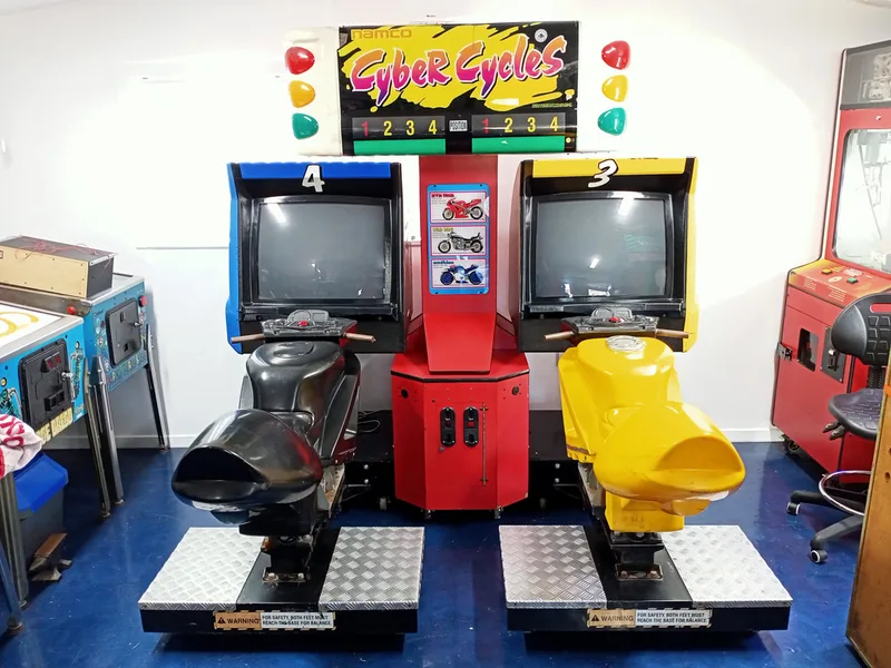
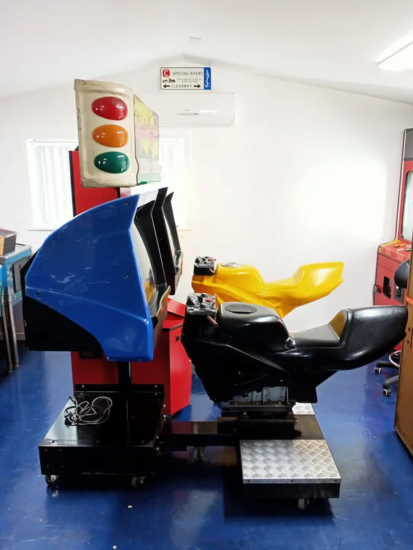
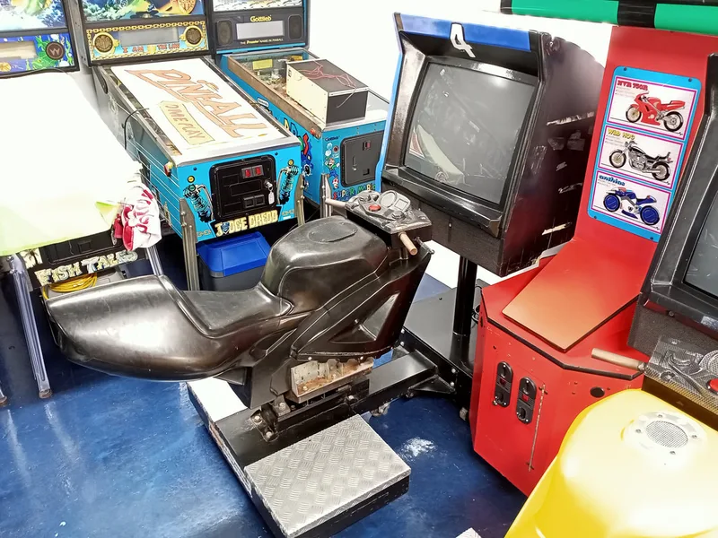
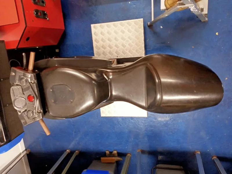
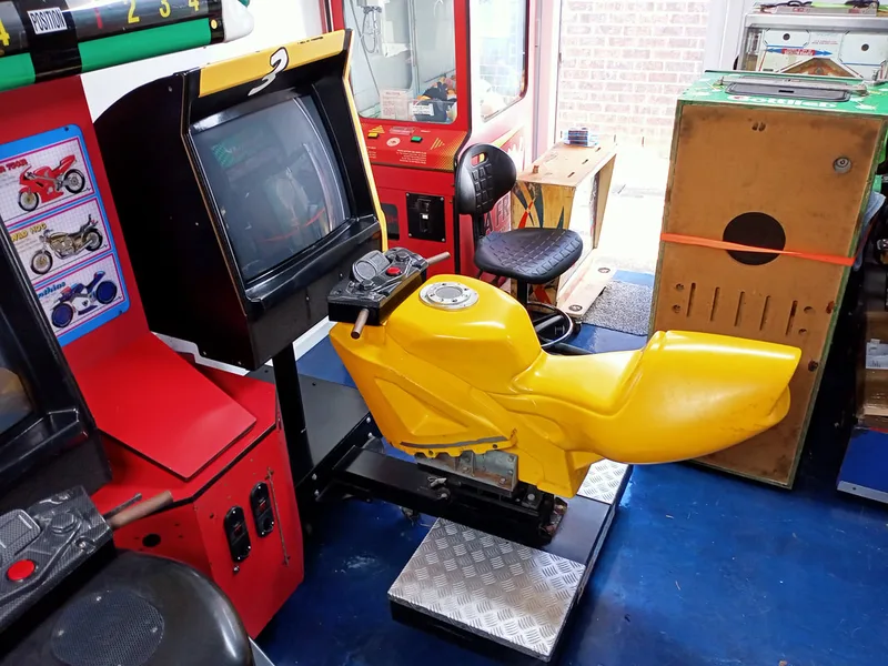
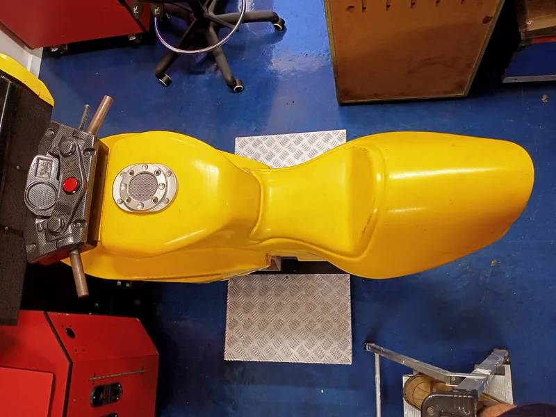
Unlike a pinball machine, there's not much to disassemble on Cyber Cycles. Luckily for me, when I bought the game, it was already disassembled and in parts. I didn't have to figure out the (dis)assembly part until after I got it back together and working. My version of the cabinet is the standard version, and is much simpler than the deluxe cabinet, which features two massive 50" projector screens. Instead, the standard (SD) cabinet utilises two 29" Toshiba monitors mounted on pedestal stands, with a tower that sits between the two pedestals and supports the topper.
From what I can tell, a couple of different variations of the standard cabinet exist. Mine is the simplest, but other pictures online show a more enclosed cabinet with sides that surround the pedestal stands. I'm not sure how common this cabinet was or where it was sold. My cabinet also appeared to be manufactured by Leisure & Allied Industries in Perth, which may account for some differences between this cabinet and pictures of others from overseas. I've uploaded the LAI version of the manual for reference. Apologies for the poor quality of some pages. The copy of the manual that came with this machine was horrible quality to start with. Some pages, such as the monitor schematic, were totally indecipherable.
The cabinet is basically split into four main parts, being the main tower assembly, topper assembly, monitor pedestal, and motorbike assembly. The motorbike assembly is attached to the monitor pedestal with four bolts on the front face, and slides onto the support bracket at the front of the pedestal assembly. There are two more bolts on the left and right sides of the support bracket which are installed once the bike has slid all of the way on.
The monitor pedestal is attached to the main tower with three bolts. A base plate on the pedestal can be swapped to the left or right side of the pedestal, depending on which side you want the main tower to sit on. Finally, the topper assembly attaches to the very top of the main tower with four bolts on the topside of the tower. Once those bolts are all removed, connectors at each section can be disconnected to separate the cabinet parts. For reference, M8 bolts (Bunnings) are used to secure the motorbike assembly to the pedestal, and the pedestal to the main tower. Each bolt should have a split washer, too. The fully assembled cabinet with topper stands quite tall (about 2.1 metres), and I had to take the topper off multiple times to get it in and out of my garage door.
Once the game was (mostly) back together, it was time to start digging into its issues. I dealt with a number of them, described below.
Tips & Troubleshooting (click on sections below to view details)
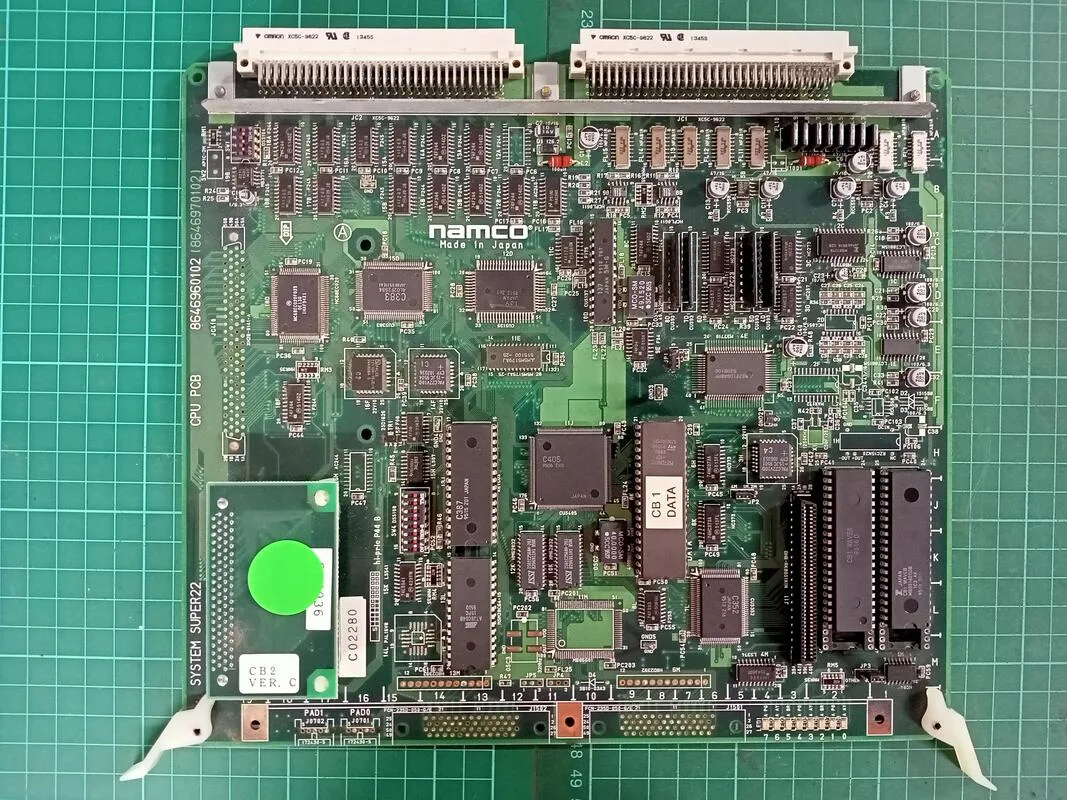
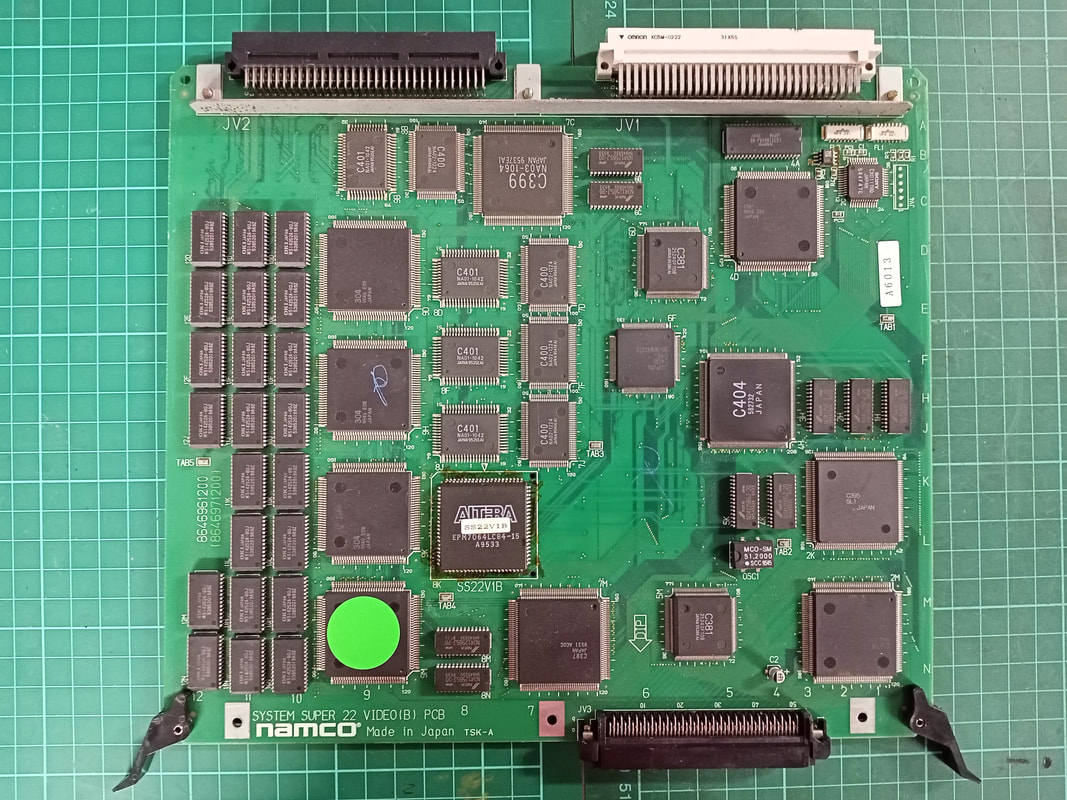
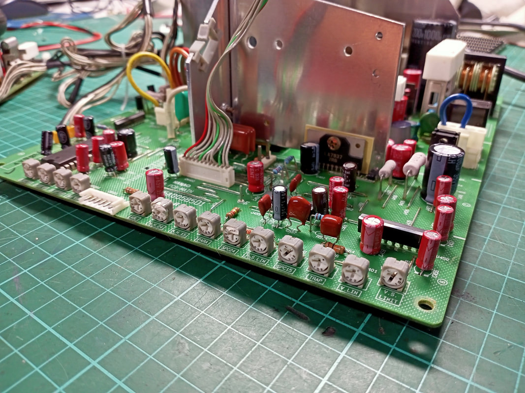
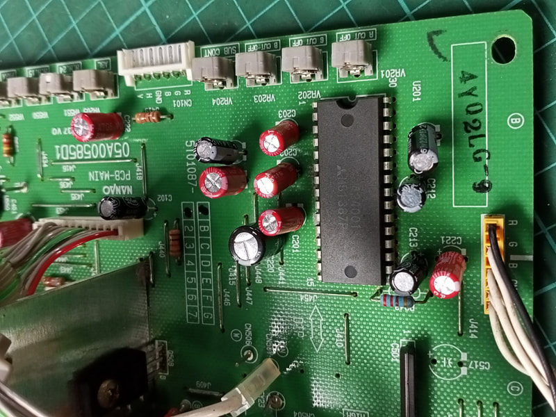
Super System 22 CPU PCB

Super System 22 Video PCB

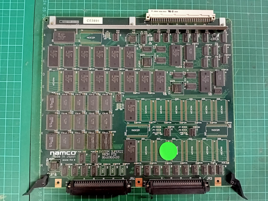
Super System 22 MROM PCB
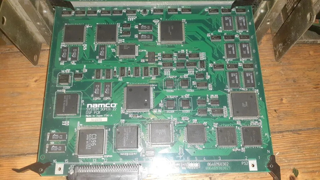
Super System 22 DSP PCB

In the process of inspecting the boards before taking them out of the cages, I realised that the board set on the working side behaved differently to the non-working side. There are a series of LEDs on the CPU board and DSP PCB which flash in a certain sequence once the game has booted successfully. The CPU board flashes its green, yellow and red LEDs in sequence (looks quite pretty!) while the DSP PCB alternates two red LEDs on and off. This is a sign of a successful boot. The video below shows a successfully booted game and how the LEDs on the CPU board and video PCB act when everything is working normally.
The non-working side only had one LED illuminated on the DSP PCB, and nothing else. So now I knew that the blank screen on one side of the cabinet was not because of a monitor issue (at least at this stage!), but was caused by a non-booting game.
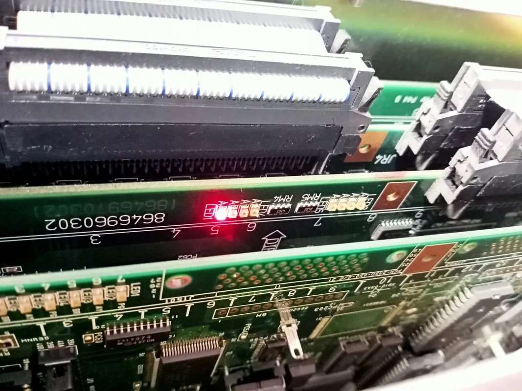
Single LED lit on the DSP board indicating an unsuccessful boot.

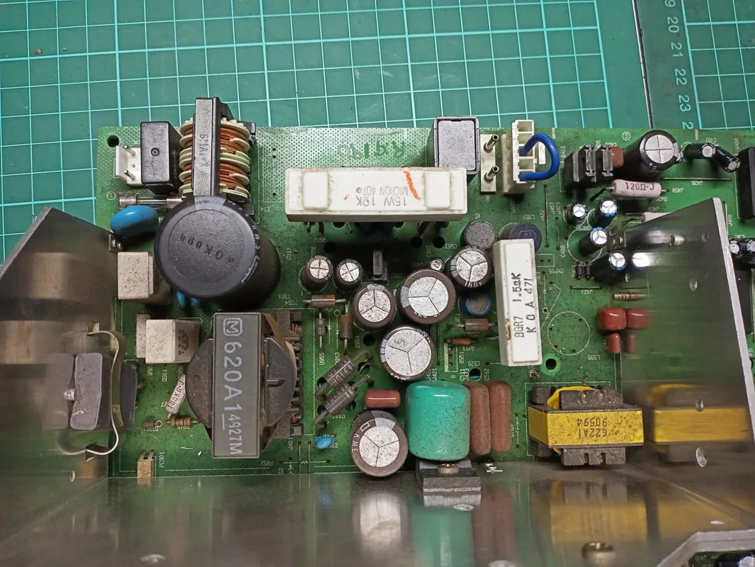
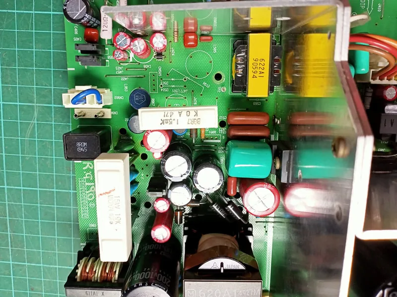
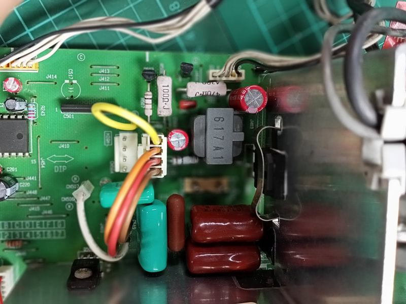
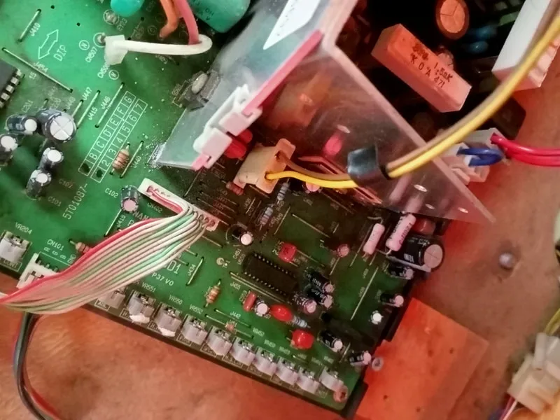
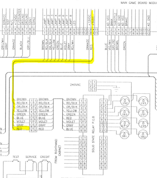
First port of call was to check that the boards were receiving the correct voltages. Cyber Cycles originally shipped with two large power supplies mounted to the side walls of the main cabinet tower. However, my cabinet was a little different and had two switching power supplies mounted to the central timber bracket which the fluorescent light fitting sits on in the main cabinet tower. I'm not sure whether these power supplies were fitted by LAI, or fitted as replacements much later down the track. It's an odd setup.
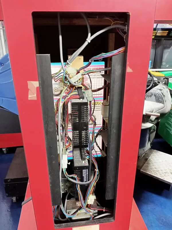
Rear of the tower cabinet with door removed showing the switching power supplies (mounted vertically).

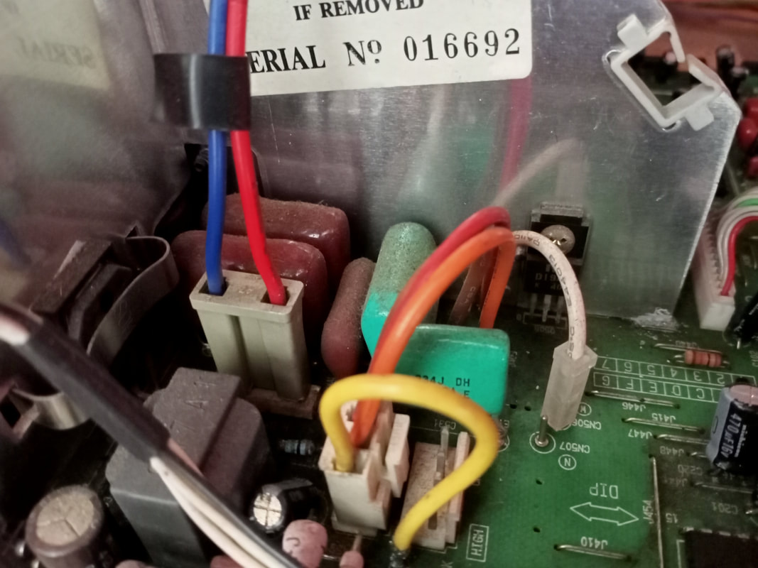
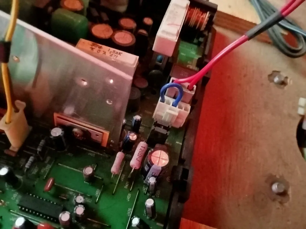
The game only needs +5 VDC, +12 VDC and GND connections in order for the game boards to boot. Other hardware such as the monitors and lamps are powered by a mains supply. A check of the voltages at each power supply showed that voltages were in spec and stable. So, probably not the source of the issue.
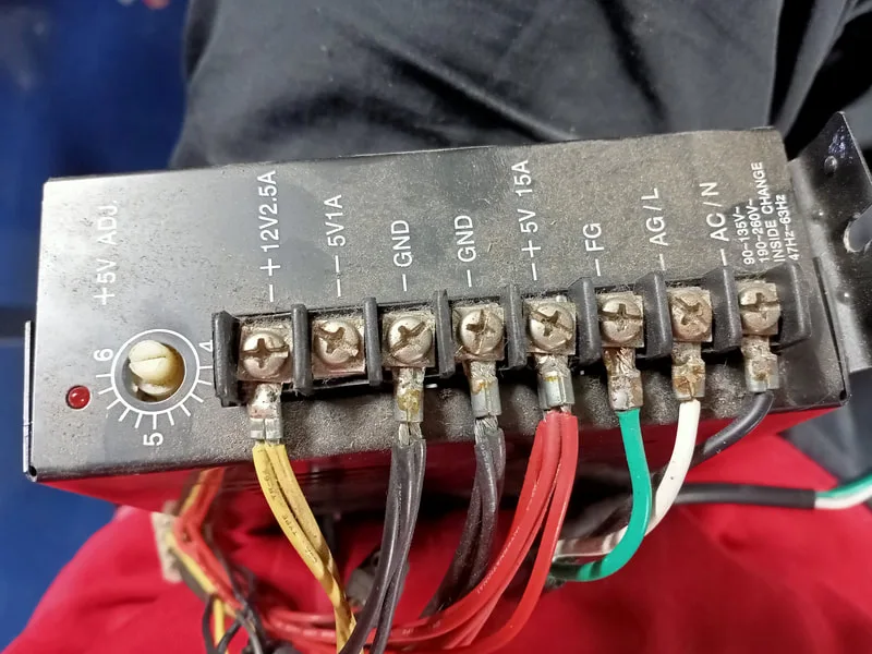
Power supply connections and wire colours.
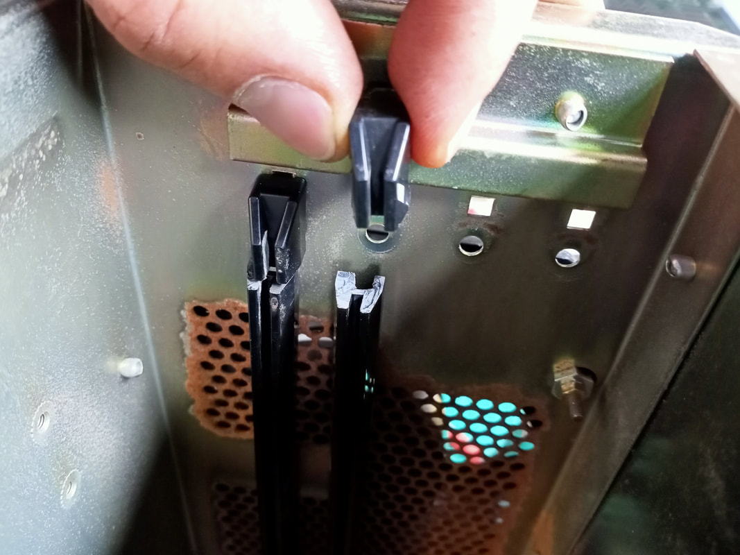
At this point I decided to swap some boards between sides to see if I could get a successful boot on the non-working side. Be careful when removing and inserting boards in these Super System 22 cages. The plastic rails on either side of the cage, where the boards are inserted, are very fragile. A number of them were broken in both cages. They screw into the cages at either end, and over-tightening of the screw can snap the rail. This is not a massive issue, but can contribute to the board not sliding into the cage properly, and therefore not mating with the PCB at the base of the cage. I wasn't able to find a replacement for the rails but they can be glued together with some success using epoxy.

Breaks in the PCB support rails.
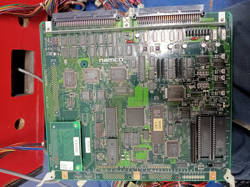
After swapping boards to and from each side, I was able to get a successful boot on the non-working side. I narrowed this down to the CPU board. The only odd thing I saw on this board was some debris in the socket for the sound sample ROM (WAVEB), but cleaning this out had no effect. I noticed one main difference between this board and the working one. There is a small daughterboard mounted in the corner of the CPU board which houses the four main program ROMs. This daughterboard is the Type 1 revision. Interestingly, the labels on each daughterboard specified different ROM versions. The non-working board was labelled with CB2 Ver C and the working set was labelled with CB2 Ver B. According to the MAME dump, the correct version number should be "CB2 Ver C". But, as is the case in my game, both versions can be used interchangeably.
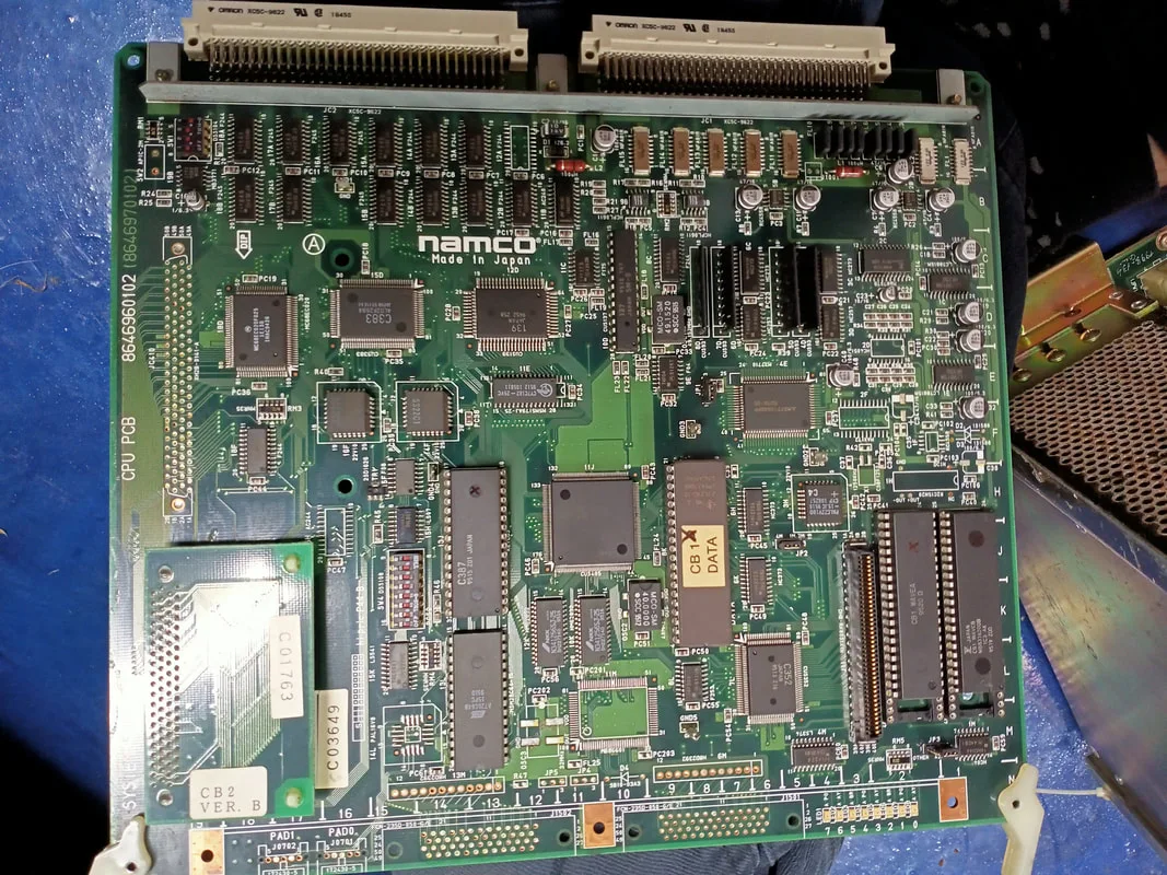
Overview of the working CPU board.

Overview of the non-working CPU board.
I swapped the daughterboard from one CPU board to the other. With the working CPU board and non-working daughterboard, I was still unable to get a successful boot. This suggested to me that the daughterboard was preventing the game from booting. I noticed nothing wrong with the connector socket, the traces on the board, or the ROM chips themselves. However, it is possible that one of these ROMs had failed. These pop up from time to time on eBay and other sites, so you may be able to get a replacement. Otherwise, you can buy a new ROM chip (Intel E28F008SA) and burn the appropriate image to it.
I cracked them open to have a closer look and check for any obvious issues. One of the power supplies looked OK, and I didn't see anything which warranted repair. The other was in poor condition. The circuit board had gone brown from thermal stress over many years. A lot of the filter capacitors were also bulging and looked like they were ready to burst! Even though they appeared to work OK, these capacitors needed changing ASAP because I didn't see them lasting too much longer in this condition.

Power supply 1: looking OK.
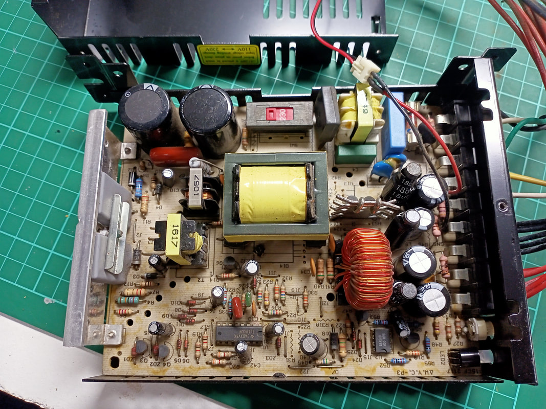
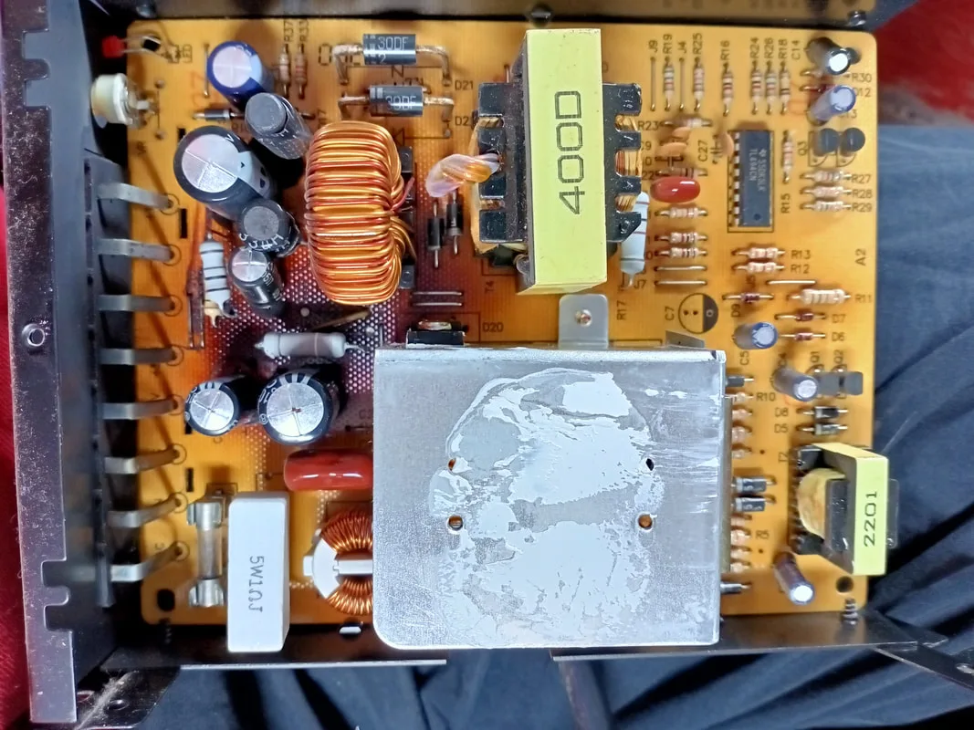
Power supply 2: looking bad!

Close up of the bulging capacitors on power supply 2.

Replacing the caps was simple enough. Luckily, I had most of the required capacitors on-hand. For power supply output filtering applications, you generally want to use low-ESR capacitors because they produce less heat, and produce less ripple voltage than high-ESR value capacitors. For cheap and nasty switching power supplies such as these, cheaper low-ESR capacitors will suffice (Jaycar), however better quality capacitors would be a good choice for a more expensive unit.
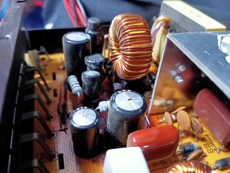
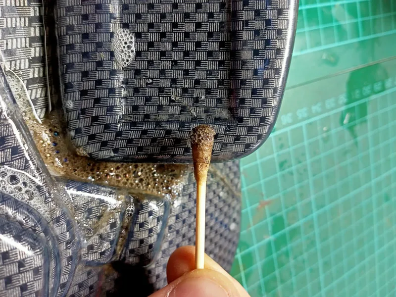
There was some crusty residue on this board which took a lot of effort to remove. It looked like the heat from the board had caused the substance to liquefy and run, but luckily it hadn't caused any corrosion or other issues.
Capacitor removal and gunk cleaning.

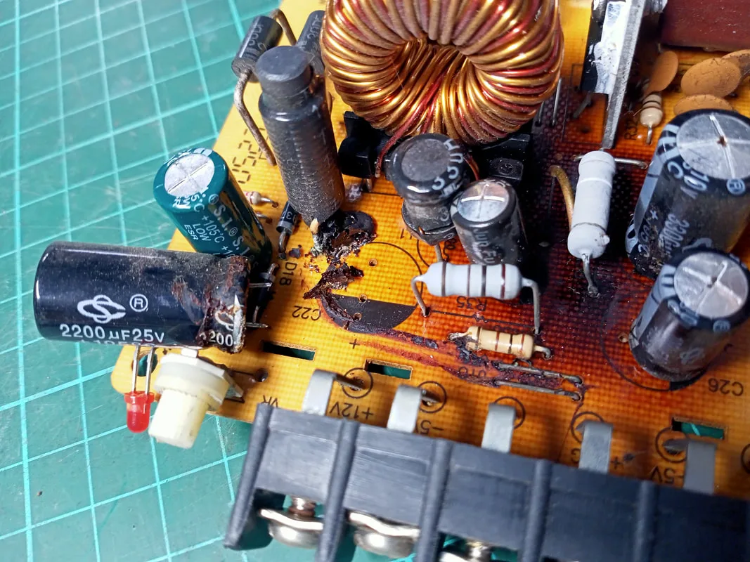
At this point things had been progressing well and I had replaced most of the bulging capacitors. There was one left, a 3300uf capacitor at C24. My problem was that I didn't have a 3300uf capacitor in my parts box. Time for some creative thinking! When capacitors are connected to each other in parallel, the total capacitance of the circuit is equal to the sum of the capacitances of each individual capacitor. There is a great tutorial on the electronic theory of this here. So, while I didn't have a single 3300uf capacitor, I did have some 2200uf, 1000uf, and 100uf capacitors spare. So, I simply connected them in parallel (each negative leg soldered together, and each positive leg soldered together) to get my desired 3300uf capacitor. Of course, you'll have to make sure there is enough physical space to install multiple capacitors where there would normally be one, but that wasn't a problem in this power supply casing.
Three capacitors connected in parallel to replace a single one.

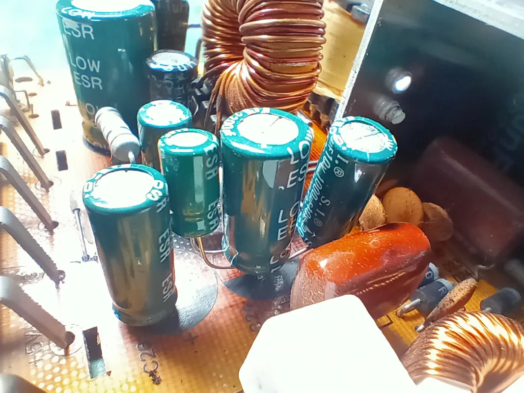
At this point, the power supply was rehabilitated and good to go. While it didn't fix any specific issues it was good to know that I wouldn't have to worry about voltage fluctuations while trying to solve other issues down the track!

Dodgy capacitors all replaced!
There are plenty of guides and videos online which describe this process, so I won't bother to regurgitate that information here. Below is a video I found particularly instructive. There are also a number of references which describe the risks, safety considerations, and discharge procedure:
- Arcade Otaku - How to discharge a monitor
- Procedure for monitor discharge with pictures
- WikiHow - How to discharge a CRT monitor
- Aussie Arcade discussion - Discharging monitors
There are heaps of videos on Youtube which document this process, too. You simply need to connect (short) the anode of the monitor to ground, most simply by inserting a probe into the hole at the top of the monitor tube (anode).
I made up my own monitor discharge tool consisting of a screwdriver and some old jumper cable clamps. Be careful if you're considering buying a cheap discharge probe from eBay or similar, as most of these are not rated to carry currents and voltages which you'd expect to see in an arcade monitor.
When discharging the monitor in a standard Cyber Cycles cabinet, you'll have to access the anode cup from the rear of the unit. A small access door can be unlocked to gain entry to the interior of the pedestal cabinet. Be careful when poking around here with the discharge tool. As is common with a lot of arcade cabinets, there is not a lot of space to manoeuvre.
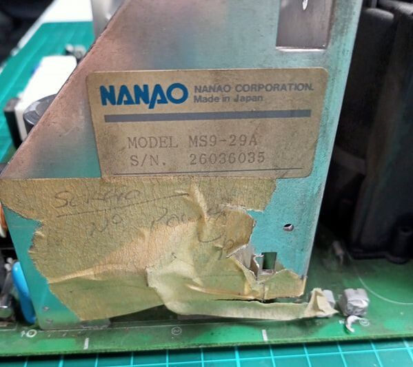
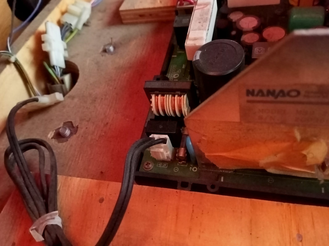
With the monitor discharged, I was able to disconnect the anode cup from the rear of the tube. Then I was able to disconnect each of the connectors from the chassis and remove it from the cabinet. The chassis used in these cabinets is a Nanao MS9-29A. This is a very common chassis used in a lot of Namco and Sega arcade cabinets. Anyone working on arcade machines would be well advised to study this chassis in detail. Michael Moffit's website has an excellent breakdown of this chassis, including specifications and maintenance tips. Arcade Otaku also has some basic information, including schematics.
The monitor chassis within the pedestal stand.
The first problem I noticed was that the chassis was sitting loose inside the cabinet. It was not mounted to a metal frame, as it would have been from the factory. Somebody removed the frame, forgot to put it back, and simply screwed the plastic chassis mounting bracket to the cabinet timber. Not cool! The frame serves as a grounding point as well as a structural support for the chassis. Most chassis are mounted to the rear of the monitor tube on an L-shaped frame, however in Cyber Cycles the chassis sit separate from the monitor. While this would not make much of a difference in terms of whether the monitor worked or not, I decided to install a new metal frame for the sake of completeness. This would also ensure the chassis could be transported inside the cabinet safely. I simply bought a sheet of galvanised steel (Bunnings) and cut it to the appropriate size with an angle grinder. Then, I drilled holes for screws to mount the sheet to the timber supports in the cabinet. Finally, I drilled holes for screws to attach the plastic chassis mounting bracket to the metal frame. Hey presto, the chassis could now be safely secured, and I could continue trying to figure out what it's problem was.

Newly fabricated chassis mounting plate.
I checked some of the basic stuff, including continuity from the power input connector to the fuse, the fuse and fuse clips, and solder joints at each connector. These all seemed OK. Curiously, somebody had discovered this issue with the chassis a long time ago and had already stuck a piece of tape to the heatsink which said "NO POWER". Looks like he got about as far as I have so far!

"No power". You got that right!
While the initial components I checked were OK, looking at the rest of the chassis, I could see that it was in poor condition. Aside from the dirt, a lot of the electrolytic capacitors had started to leak and corrode. I was sure that most, if not all of these, would need replacement. As a test, I installed this chassis into the other monitor pedestal and turned on the game. No dice! Even though this monitor was confirmed working, it wasn't displaying anything with this chassis. Then, I put the working chassis into the non-working side. The tube turned on and functioned normally. Colours were nice and bright and the image was stable. So, the tube was OK. The source of the problem was definitely the chassis. As an aside, I also broke a resistor off the board when unplugging the blue and red (horizontal yoke) connector, so that needed replacement as well.

Non-working chassis - top down view 1.
Non-working chassis - top down view 3.


Non-working chassis - top down view 2.
Non-working chassis - top down view 4.


Broken resistor (R516) near the horizontal yoke connector.
At this point I have to admit I really don't have time in my life to study the things I wish I knew more about. I am not particularly familiar with chassis repair and there was a lot of other work to do on this game before I could get it going again. As a result, I wasn't keen on dedicating the time to learning how to repair this chassis properly. So, I decided to outsource the repair. Luckily in Australia we have Joey at JOMAC who is a whiz at repairing monitors and chassis of all types. I highly recommend Joey's services to anyone who needs a chassis repaired. He does a great job for a reasonable price. The chassis came back looking brand new, with high quality Wurth Elektronik capacitors installed throughout. The whole chassis had been washed and cleaned, too. It looked brand-spanking new!
Repaired chassis - top down view.


Repaired chassis - top down view 1.

Repaired chassis - side view 1.
Repaired chassis - top down view 3.

Repaired chassis - underside.


Repaired chassis - top down view 2.
Repaired chassis - side view 2.


Repaired chassis - top down view 4.
As could be expected, once I installed the repaired chassis onto its new metal mounting frame and turned the game on, it worked like a charm. Monitor issue fixed! For reference, below are a number of images showing correct orientation of connectors on the chassis. Connecting the yokes upside-down will result in some funky image orientation, so make sure they are oriented correctly.

Position of horizontal yoke connector (blue and red wires).
Position of degaussing coil connector (red wires).

Position of vertical yoke connector (yellow and brown wires).

Position of power input connector.

Chassis reinstalled into cabinet with new mounting plate.
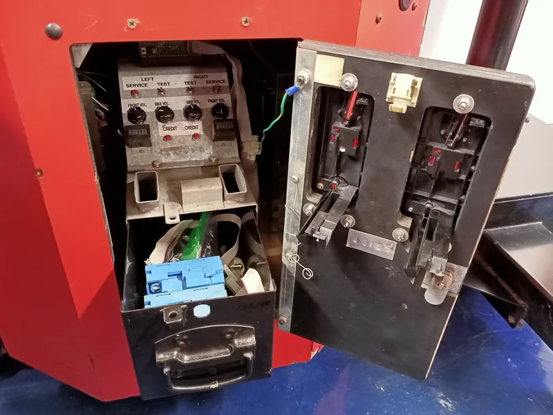
Microcoin mechanisms work by comparing an inserted coin to its library of programmed coins to assess whether it is a valid coin. If it is, it diverts the coin to the accept path, and drops it into the coin box. The mechanism them sends a "pulse" to the game CPU to register that a coin has dropped and a credit needs to be added to the game. Each coin is programmed to have a specific value, such as 100 for a $1 coin. An accumulation threshold value is set, such as 200, which will trigger the mechanism to pulse the game CPU when the threshold is met. In this example, two $1 coins would meet the threshold, and would result in a single credit being added to the game.
Luckily, I have a Micromate programmer from when I bought a bunch of spare parts a couple of years ago. I had debated selling this thing multiple times but I figured it would eventually become useful one day. Well, today is the day! The issue is that the programmer must be connected to a power source as well as the mechanism being programmed. I needed to do a lot of checking and research into the programmer's settings, which was going to be hard to do while sitting in front of the game coin door with the programmer. So, I decided to do all of the mechanism programming on the workbench. To do this, I used some pins and alligator clips connected to my benchtop power supply to supply 12 volts and ground to one end of a ribbon cable. Pin 1 of the cable is for 12 volts, and pin 16 is ground. The other end I plugged into the interface board, which was connected to the programmer and the coin mechanism. This setup worked well for programming the mechanisms out of the game.
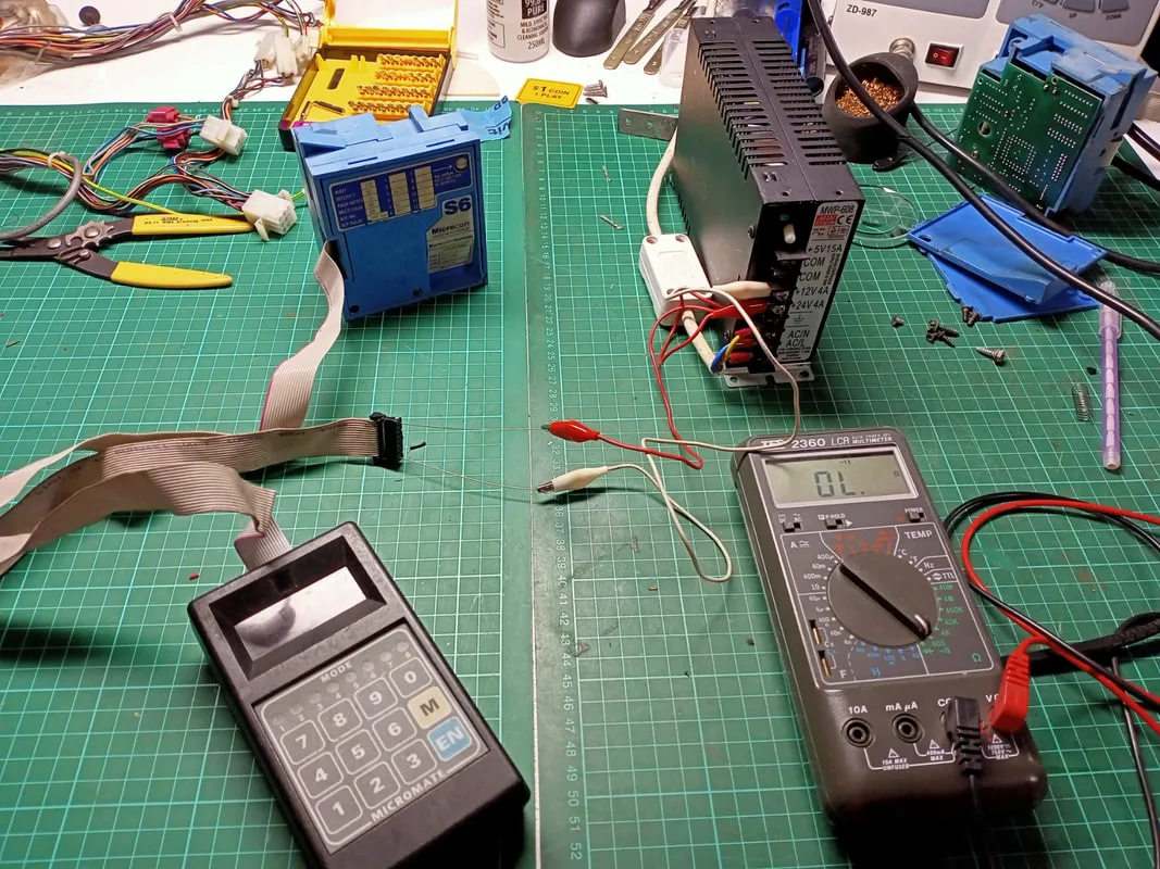
Setup used for programming the S6 coin mechanisms on the bench.

As I did not have an S6 mechanism manual, it took me a bit of trail an error to figure out how the settings differed from the S5 manual I found online. Eventually, I found an archived website which contains instructions specific to the S6 mechanism, which made everything a lot clearer!
The first step was to start with a clean slate. I cleared all programmable variables using Mode 8. Now I wouldn't be hamstrung if there were some weird settings programmed into the mech previously.
Next step was to decide what coins I wanted the mechanism to accept. I decided I'd set it up for 10c, 20c, $1 and $2 coins. Mode 6 on the programmer allows for new coins to be programmed. Enter Mode 6, Select a coin category, and then feed 10 exemplar coins into the mechanism. I set the coin categories to 2 for 10c, 3 for 20c, 5 for $1 and 6 for $2. The display goes blank when the last coin is dropped. Enter 1 to select normal discrimination rules and press EN to finish.
I then entered Mode 5 to set the values for each coin. I used 10 for 10c, 20 for 20c, 100 for $1 and 200 for $2. You'll need to select the appropriate coin category (as set in the previous step) to adjust the right value.
Next, I made sure that the newly programmed coins were enabled for use. This is set in Mode 3. Make sure this is set to 1 (enabled) for each of the coin categories above. For some stupid reason, newly programmed coins are not automatically enabled, which caused me a lot of confusion initially!
The final step was to set the accumulation threshold in Mode 4. This was the value at which the coin mechanism would actually issue a credit. I set this to 200 (based on the coin values I set above, 200 is equivalent to $2) however this can be adjusted depending on how much you want to charge per game.
Note that Cyber Cycles additionally allows you to set credit values in the coin options menu. The game can be programmed to require from 1 to 9 credits for a game. I set it to 1 credit per play. Combined with the accumulation threshold of 200 from the coin mechanism, this meant that the game was set to $2 per play.
The combination of game coin settings combined with the coin mechanism programming means there are two ways to get the game to accept a credit. If the credits required setting in the coin options menu is set to 1 per game, the accumulation threshold in the coin mechanism must be set to the value of a single credit. If the credits required is set to 2 credits per game, the accumulation threshold must be set to the value of half a credit. For example, with the settings I used, a single $2 coin would credit up the game. Alternatively, I could set the coin mechanism accumulation threshold to 100 ($1 equivalent) and set the coin settings in-game to 2 credits per game. This would still require a total of $2 for a game. Insertion of only $1 would result in an "Insert another coin" prompt in this case.
I had no reason to fiddle around with the discrimination band, pulse width or output line settings. I left these at default vales.
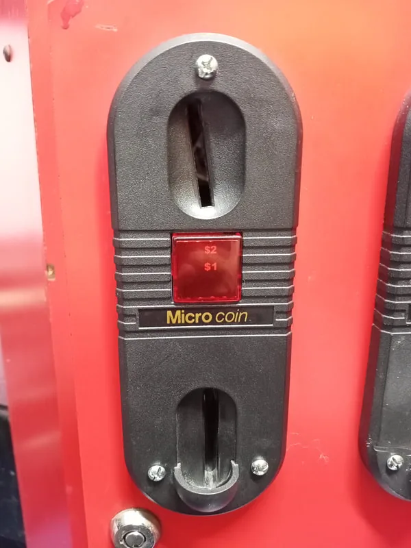
Another issue with these Microcoin mechanisms is that they require a specific faceplate on the coin door. The faceplate has bolts moulded into the plastic of the faceplate which the coin mechanism attaches to. The problem is that the plastic holding these bolts eventually breaks or snaps off, which causes the bolt to fall away, where it can no longer support the coin mechanism. Some excellent pictures of how these faceplates are supposed to look were posted by poidapoida on Aussie Arcade. Unfortunately, the one faceplate I did have had the bolts broken off, so I wasn't able to mount the coin mech to it. This is the problem when using bolts embedded into plastic housings which break easily!
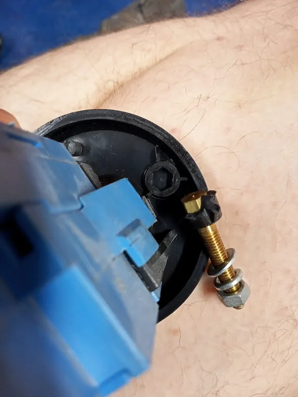
Bolt broken from its housing on the faceplate.


Three broken bolts, all with plastic from the faceplate still stuck to them!
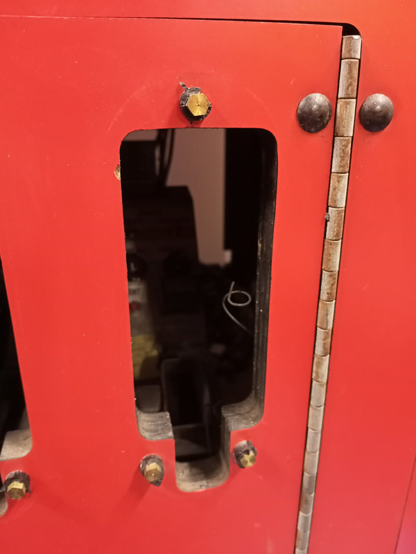
These older style faceplates are no longer available anywhere, so unless you can purchase a second hand unit, you are out of luck. I decided to try and make my broken faceplate usable by drilling some holes into the faceplate through which I could install some bolts. These could then be secured with nuts on the other side, locking the faceplate into place. This solution isn't ideal because there are now screws facing outwards to the customer, but you can use security screws if you want to prevent any tampering. For home use, this isn't a big deal. But now I had a useable faceplate instead of junk!
Coin door front view showing new bolts for faceplate mounting.
Coin door rear view showing nuts holding faceplate bolts in place.

This Cyber Cycles only had one faceplate, so I had to try and find another. I put out a call for help on Aussie Arcade, and AskJacob came to my rescue by selling me one of his spares. Thanks Jacob! A couple of the plastic sections around the bolts had been broken, just as they were on my first faceplate, so I performed the same procedure as above to secure the faceplate to the coin door. It worked, and now I had a place to install the second coin mechanism. Nice!
Two faceplates, repaired and installed.
Blurry "Cyber Cycles" text.


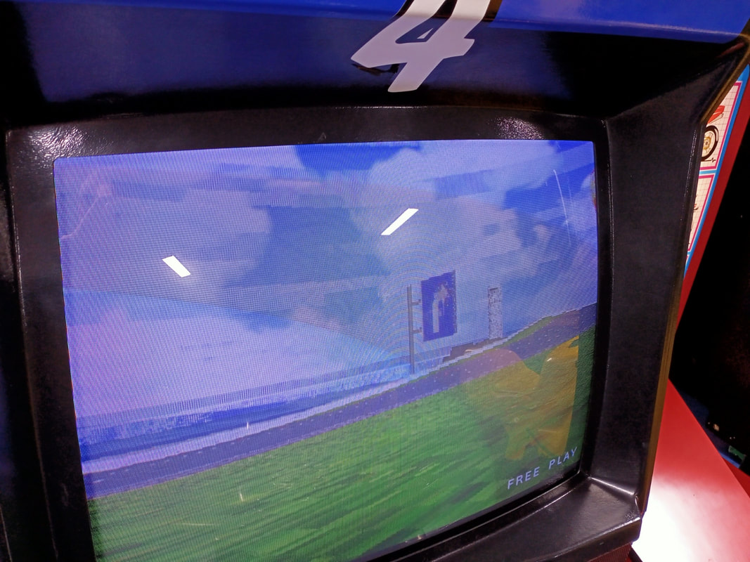
Horizontal lines appearing in the sky.
Blurry "RANKING" text at top of screen.

More lines in the sky, and a blurry street sign texture.
First step was to swap some PCBs between board stacks and narrow down the issues to a specific board, or boards. In doing so, I found that two of the boards were at fault.
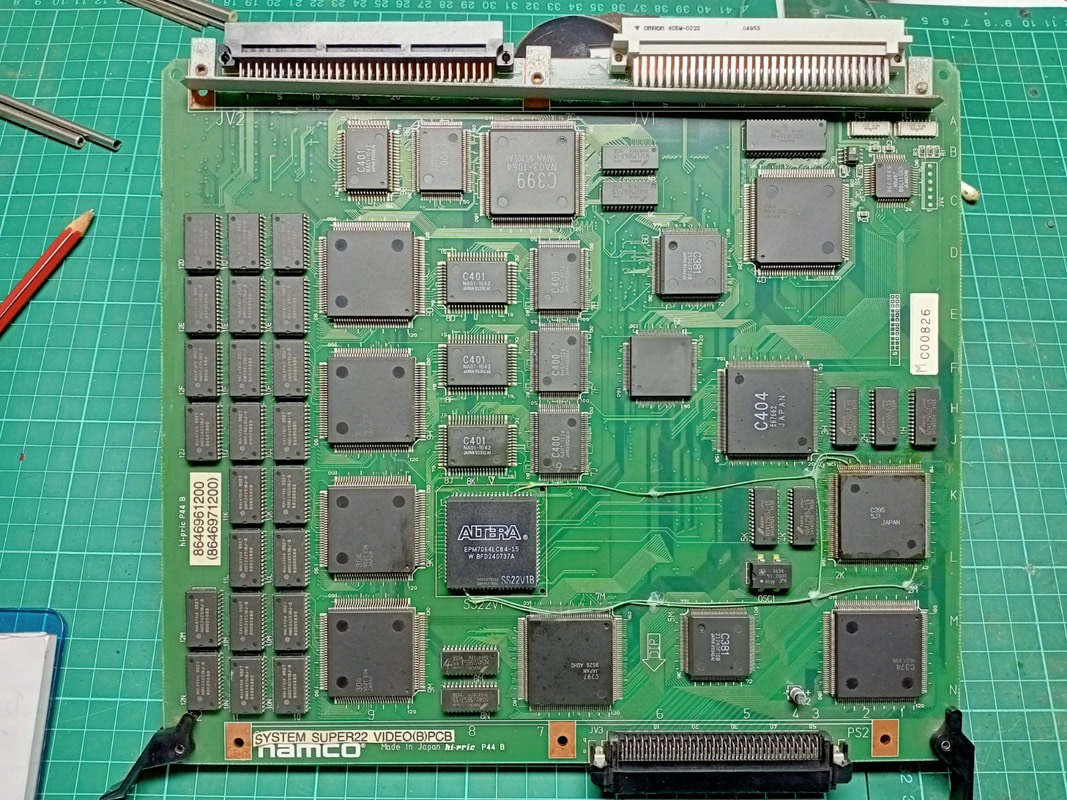
The video PCB was responsible for the low resolution textures and garbled text. In terms of the video PCBs, there were two PCB revisions represented in the board sets I had. These were: an unmarked A revision, and a marked B revision board. The B revision board had a number of jumpers installed on it connecting the ALTERA FPGA chip to the custom Namco C395 chip. The sticker covering the original board designation leads me to think that this modification was done at the factory, and is the main difference between the A and B revisions of the board. A C revision also apparently exists, which replaces the ALTERA chip which tends to get incredibly hot and fail. The sticker attached to ALTERA chips on my revision A board had started to char a little - pretty good evidence of thermal stress!
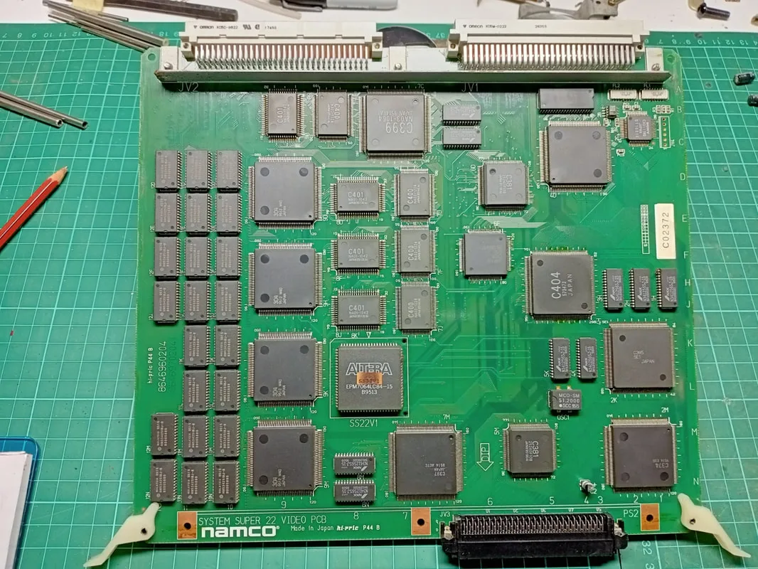
Revision A of the Video PCB.


Revision B of the Video PCB, with jumper wires.
The MROM PCB was responsible for the intermittent vertical lines which appeared randomly across the screen. I couldn't see anything wrong with the board from a visual inspection. As this board is covered in masked ROMs, any one of them could have been the one causing the issue. Guru also suggests that mask ROMs are responsible for these kinds of issues (scroll down to his post on 15 May 2020). That advice seems to be fairly well known. I probed all of the ROMs with my multimeter in diode test (this took forever) but couldn't find an issue. However, that type of testing wasn't in any way conclusive. Doing some research I found one other person who seemed to have similar graphics glitches, but there was never any update on whether the problem was fixed or not.
When I got them back, I realised that they were different boards. Joey had swapped my boards for known working ones in order to expedite the repair process. All cool with me! They both worked without issue, and the graphics issues were gone.

"Cyber Cycles" text now displaying properly.
No more weird horizontal lines in the sky!

"Ranking" text displaying properly.

Street sign textures were readable again.

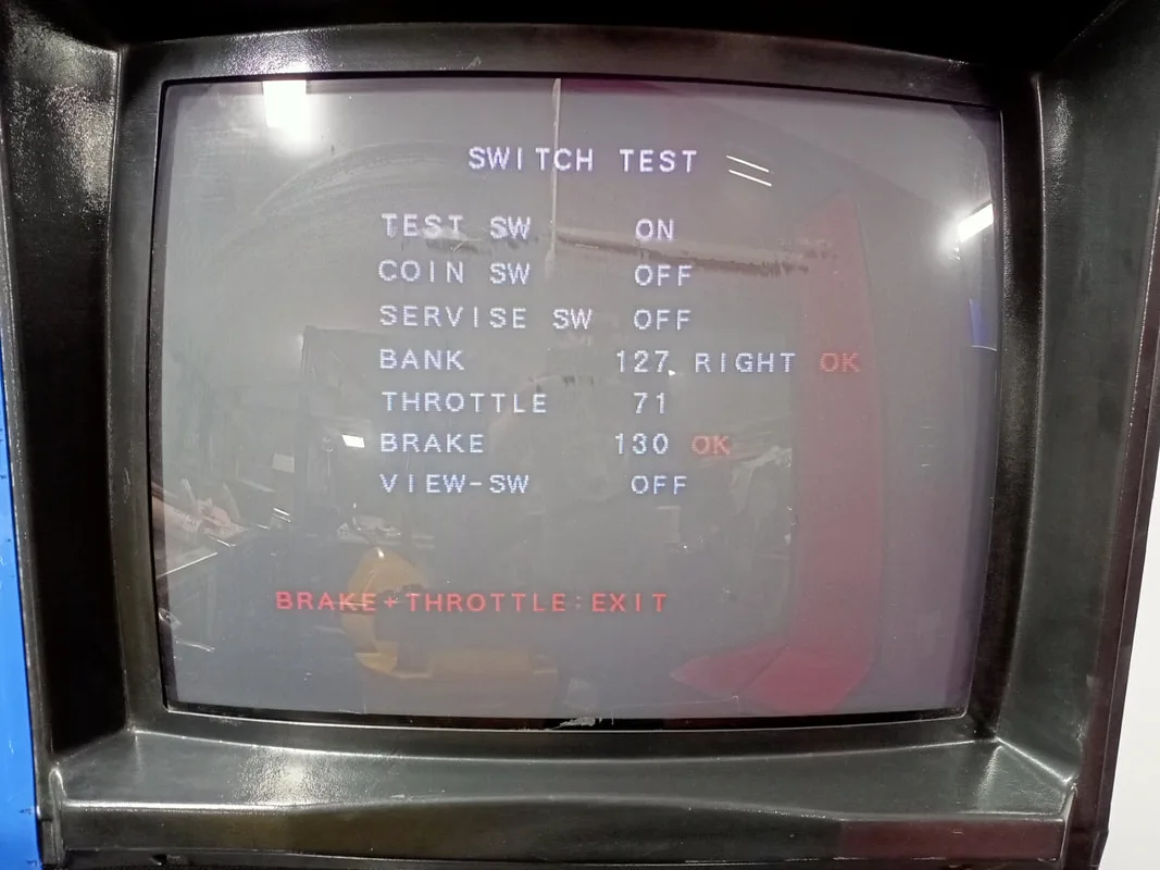
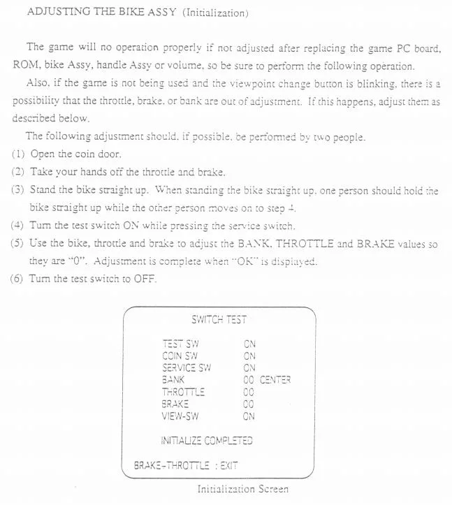
Switch test showing brake and bank potentiometers fully engaged.

While this may have been a hardware issue such as a fault on the board, I considered that the CPU board also stores all of the game settings. Part of these settings are the potentiometer range adjustments. There is an in-built initialisation function which zeroes all of these adjustments, and the manual states everything should be initialised whenever a potentiometer is replaced, or when the CPU board is replaced. This has the effect of basically resetting all of the potentiometers, so if they have been adjusted or replaced, the game knows that their new position is the new "zero point". I initially thought that initialisation was performed at game start up (as many other manufacturers' game system do). However, Namco does not do this, and initialisation must be done manually. Simply hold the service switch on, and flick the test switch at the same time. Ensure the motorbikes are centred, and the brake and accelerator are not being activated. Once the potentiometers were all initialised, the issue went away. The bike performed normally in-game and the test menu options could be scrolled through as intended. This turned out to be an easy one!
Game initialisation procedure.

Metal strap holding the cabinet base together.


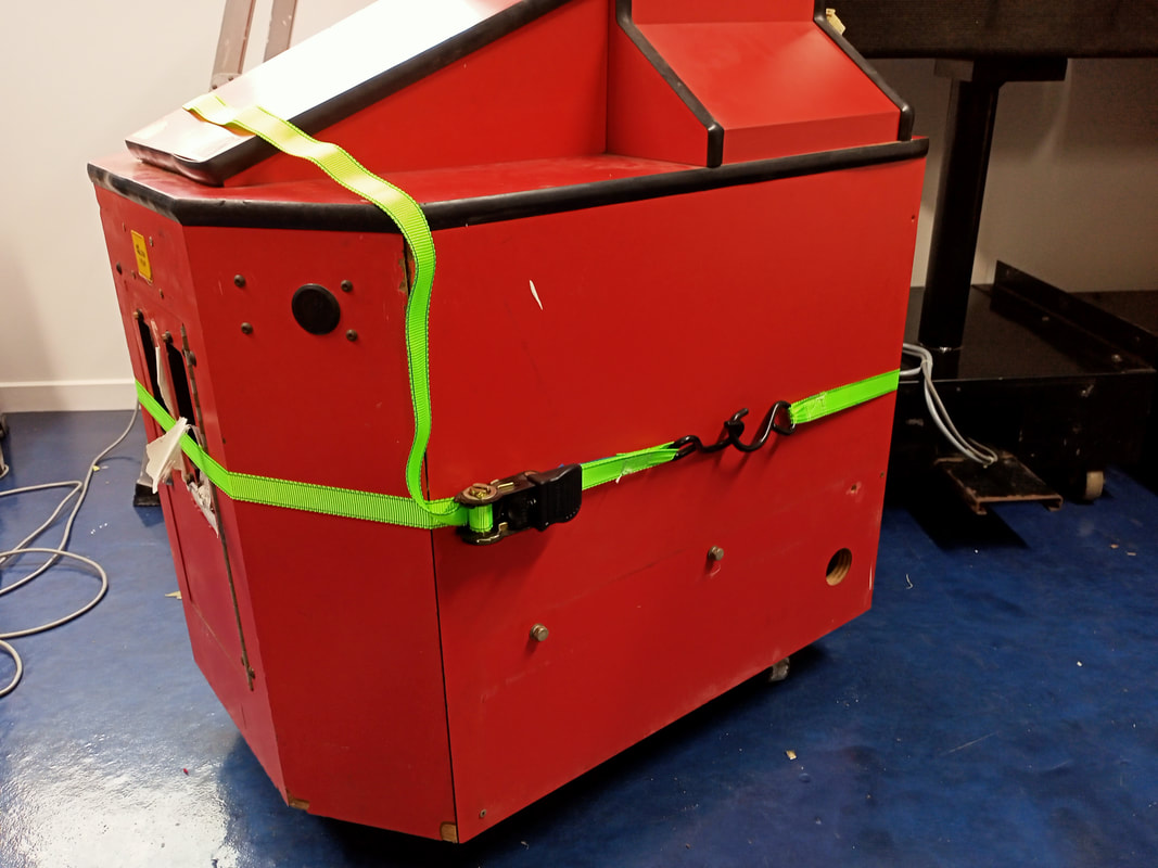
Removal of the side timber panel which was loose.
The metal strap was cut with tin snips and with a little encouragement, the timber panel was worked free from the cabinet. It was held in place by one small section of timber that was still intact, but this broke off fairly easily once I started prying at it. Once the piece was cleaned and stray fragments of timber removed, it was ready for reattachment. A thick bead of liquid nails (Selleys) was enough to reattach the timber piece, and a couple of ratchet straps (Bunnings) were used to clamp it into place while the glue cured. Additionally, there are a number of screws that secure the side timber panels to the floor and ceiling of the cabinet. I found these screws on the floor of the cabinet, so they went back in at this point as well.

Using a strap to secure the timber panel after gluing.
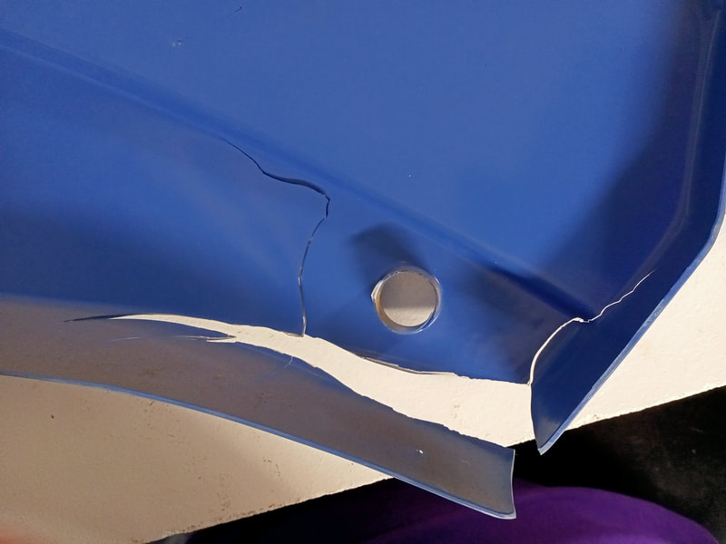
That was all the work necessary for the bottom part of the main tower assembly. However, the topper also needed attention. This topper was in very poor shape and had obviously had a hard life. It had been smashed and cracked in several places. There were some large cracks in the front acrylic which had been glued together previously. Another piece of acrylic had been glued to the rear, to support either side of the crack. Not a bad repair! Unfortunately, a piece had broken off from the top left of the front acrylic as well, and that was nowhere to be found. As the cracks had already been repaired by someone, there wasn't much else for me to do to this piece.
However, the traffic light plastics on either side of the topper needed attention. The traffic light on the left was cracked in many places, while the one on the right was pretty much intact. Somebody had attempted to patch some of the holes in the left light with fibreglass resin, as well as gluing some of the cracked sections back together. They actually did a pretty good job, but some of the cracks had broken again and it was going to be hard to attach the traffic lights to the topper without putting a lot of strain on the remaining plastic. So, they had to be glued back together.

Evidence of previous repairs on the rear of the traffic light plastic.
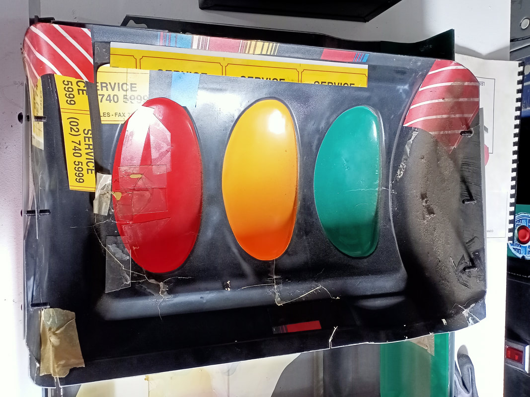
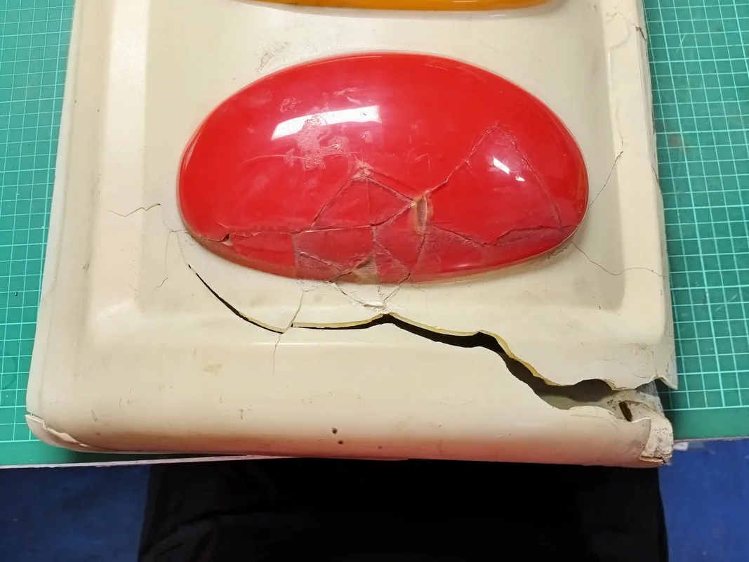
Some of the cracks opened up again!

For these kinds of plastic repairs, I like to use 5-minute Araldite (Selleys). This is a two-part epoxy mixture which dries clear and hard. I like the 5-minute version as it dries quickly enough that you can hold the pieces together for long enough for the initial cure to complete. You actually have a working time closer to two minutes, so you still need to be fast. Don't bother with the 90-second version of the product as it sets way too fast to be useful. A few beads of the two-part glue on each side of the crack, and then clamp together. Get someone to help you hold things in place as it is hard to work quickly enough when the cracks are this large. After leaving for a day to cure, the traffic lights were ready to reinstall.
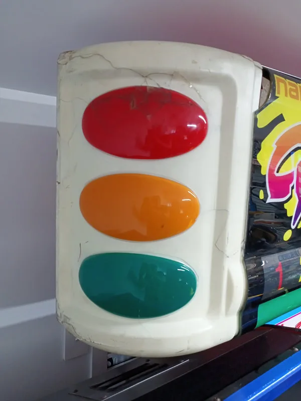
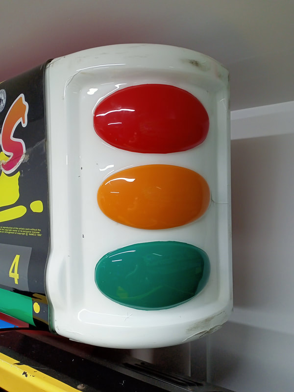
Repaired traffic light on left side.


Intact traffic light on right side.
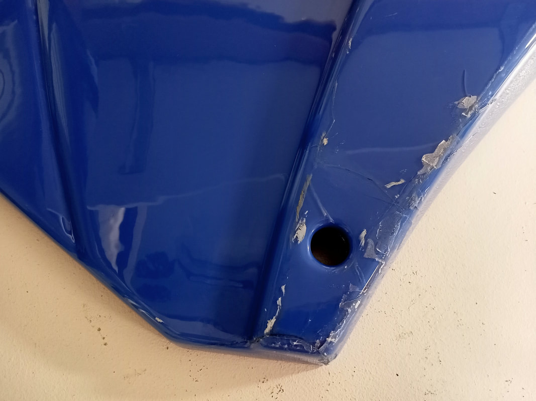
The one issue remaining was that pieces of plastic had cracked off the traffic lights as well as the front acrylic at the top edges. This was probably from over tightening of the bolts which secure the plastics to the topper. However, without enough screws holding the plastic in place on the top edge, there was a risk that the traffic lights and the front acrylic would not be well supported enough, and would eventually fall down.
To deal with this, I decided to reinforce both the top and the bottom edges of both traffic lights and the front acrylic. For this I simply used a length of aluminium (Bunnings) and cut it to the length of the plastic. Then, I drilled holes in it to match the position of the bolt holes in the traffic lights and the front acrylic, respectively.
Determining position of bolt holes to match spots where the plastic is gone.


Holding the aluminium up against the plastic to determine bolt positions and length.
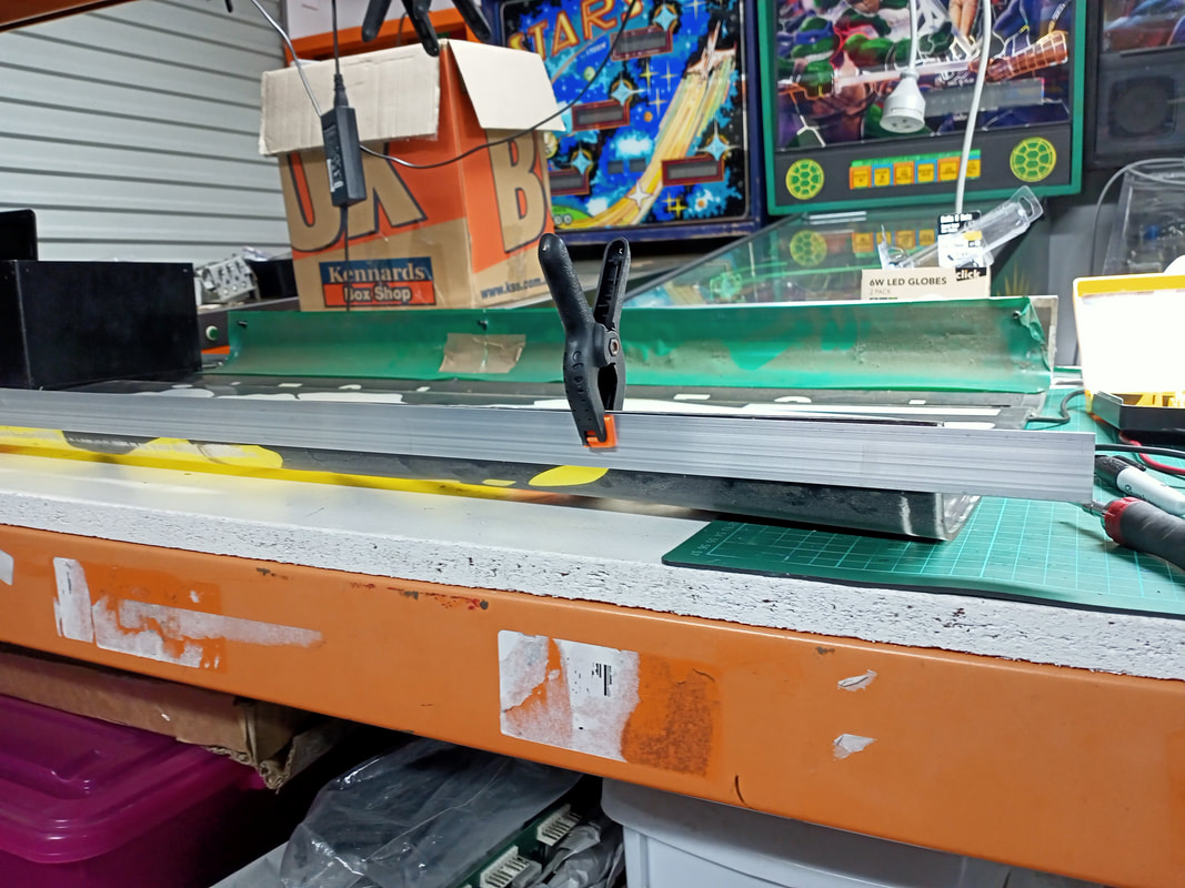
Then, I bolted this into place over the top of the original plastics. This provided some additional support in the areas where the plastic was compromised. In the absence of complete replacement plastics, this is a pretty good fix to ensure the plastics don't break further. There should have been some kind of channel or bracket which the plastics could slot into before being bolted down, but alas, they didn't think about this at the LAI factory!

Aluminium strip bracket added to topper (topside).
Aluminium strip bracket added to topper (underside).

One part of the cabinet left to go! Like the topper, the plastic sides of the monitor pedestal assemblies were in rough shape. They had also cracked in various places, which made it difficult to reattach them to the sides of the monitor assemblies because they were so flimsy. Luckily, 5-minute Araldite (Selleys) came to the rescue once more, and both the blue and the yellow sides had some cracks repaired. The repaired plastics were much stronger and stayed properly in place when finally bolted to the sides of the monitor pedestals.

Cracks to the blue plastic on the side of the monitor pedestal.

Cracks repaired!

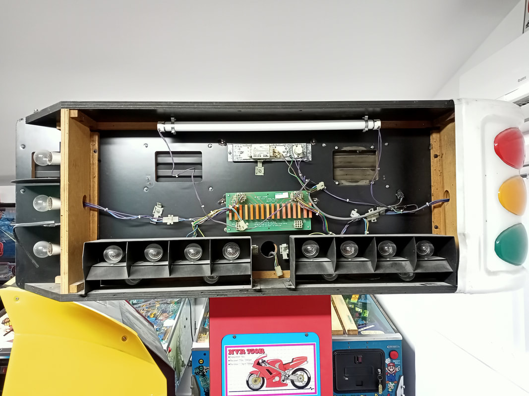
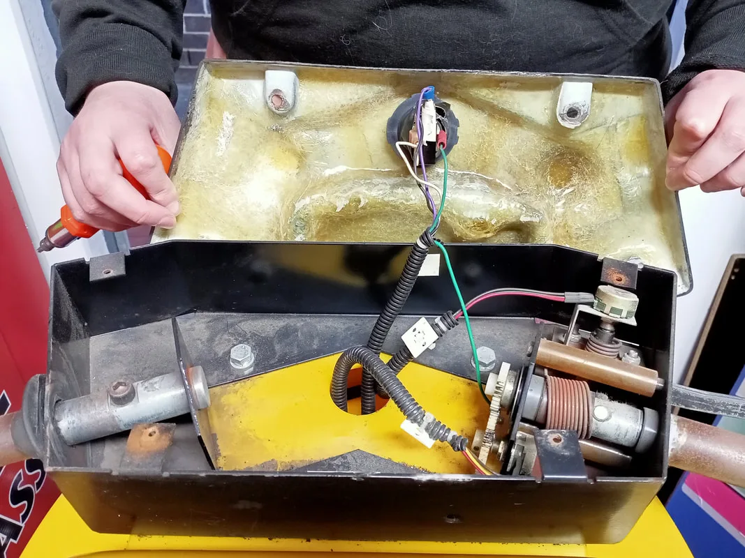
Original state of the topper internals, showing fluorescent tube and incandescent lamp fittings.
Let's deal with the fluorescent lamp first. The tube was not lighting up, and due to the blackening at one end of it I thought it was a safe bet to simply replace the tube. This is no big deal, as the tube is a T8 tube, 600mm long. Plenty of replacements are readily available (Bunnings). Don't forget to replace the starter, too (Bunnings). However, I ran into some issues when it was time to replace the tube. While checking all of the wiring was intact, I accidentally snapped the end off the ballast where the active and neutral wires connect to it. Bugger. This is the problem with fluorescent lights, as they emit ultraviolet radiation which damages plastic and makes it brittle.

Broke the wiring off where it connects to the ballast.
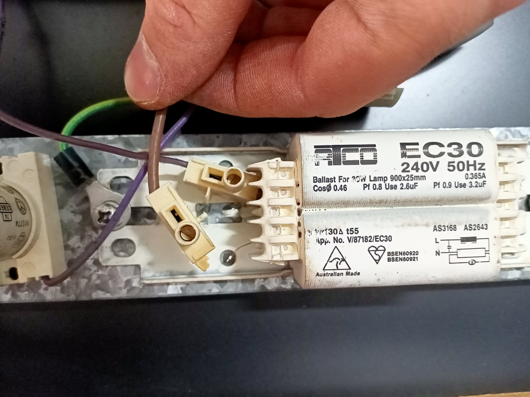
There was no way I could reattach the conductor to the ballast in a safe manner, so off I went to buy a complete fluorescent lamp fitting. Normally I would just replace the ballast, but it is easier to simply buy a complete fitting and remove the ballast from that. However, once I got the fitting home, I decided it would be simpler just to install the new fitting as a complete unit (Bunnings). Much less messing around that way. I mounted the fitting to the top edge of the topper with a couple of screws, and had it wired into the existing wiring. And now, we had general illumination again.

Testing the new fluorescent lamp fitting for proper fitment.

Lamp fitting installed, just need to put the tube in.
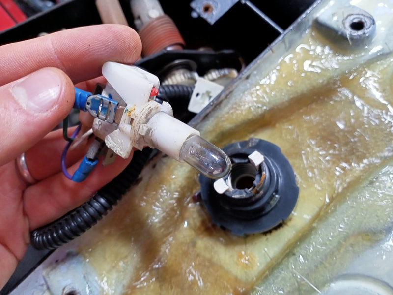
The next issue was the replacement of the incandescent controlled lamps. All of the lamps were dead with broken filaments. I normally expect to see a few blown bulbs but seeing all 18 lamps broken was interesting. Anyway, time to replace them. I prefer to replace incandescent lamps with LEDs, as they run much cooler, draw less current, and last much longer. Purists may not like it, but just like replacing general illumination lamps with LEDs in a pinball machine, I think the pros outweigh the cons. Suitable LED lamps are readily available (Bunnings). However, the problem with these is that the opaque plastic shroud which covers the LEDs is much larger than the original glass bulb. So, it doesn't actually fit into the metal lamp enclosures. The solution to this is to simply cut or break the shroud off the base of the lamp, leaving only the flat surface with LEDs mounted to it. This allows it to be slid into the enclosure and inserted into the bayonet fitting. You only need to do this to the four lamps on the very bottom row, which light up the green strips at the bottom edge of the topper.
Removal of the shroud around the LED so it can fit into the enclosure.

When I turned the game on to test all of the lamps, I noticed another problem. One of the lamps, the one for position no. 4 on the left side, was constantly lit. It wasn't an issue with the lamp itself, as swapping it to another fitting showed that it worked properly. In the photo below, the game is in lamp test. All lamps on the right side of the topper are meant to be on. However, there is a single lamp on the left side which is on when it should not be.

The lamp under the circuit board and to the left is not meant to be lit.
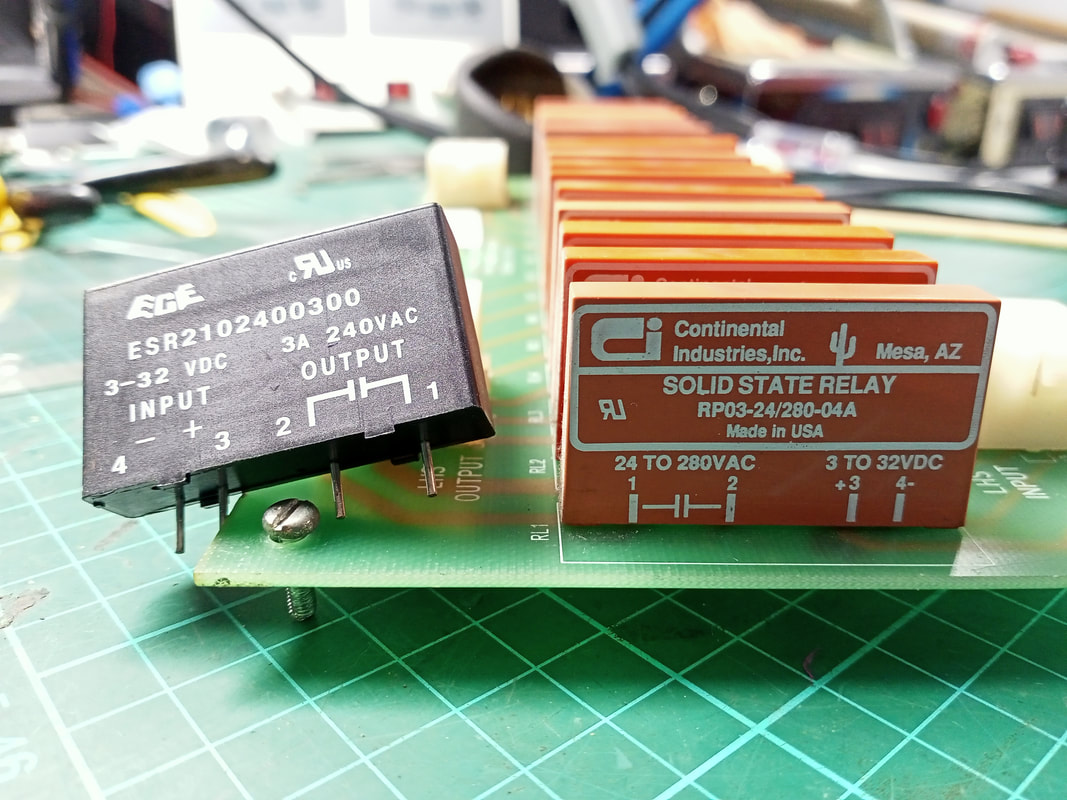
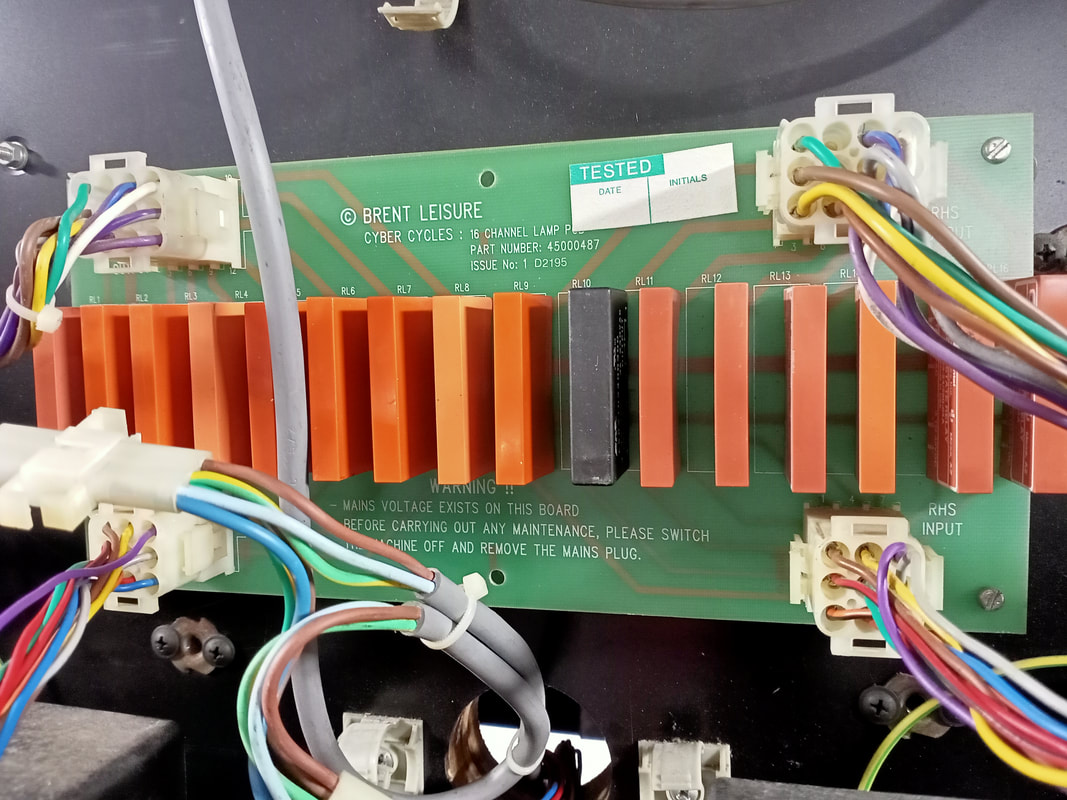
The lamps are controlled by a relay board in the centre of the topper. This inputs from the CPU, and sends mains voltage to each lamp holder via a relay. I suspected an issue with this board. As the only components on the board are identical relays, I just followed the wires from the problem lamp holder to the controlling relay on the board. To confirm this relay was the problem, I actually desoldered it as well as a working relay, and swapped them over. The problem moved to the other lamp, and the previously non-working lamp started working again. That confirmed the relay was the issue. Although expensive, you can buy suitable replacements relatively easily (Jaycar). The main consideration is that the relay needs to be able to supply 240 VAC to the load, and it needs to be turned on by a 5 volt signal from the CPU. Any relay meeting those specifications will suffice. Once the new relay was in, the lamp worked! Problem solved.

New relay (left) compared to original relays (right).
Lamp control board reinstalled.
Highlighted 5 volt signal from the CPU makes the lamp relays turn on.
The use of LEDs does introduce one other problem, though. Because the LEDs respond to very small amounts of current which incandescent lamps would ignore, most of the topper lamps "ghosted" a little. This meant that, even when off, they stayed very slightly lit. There's not really a way to fix this issue without modifying the circuit, but I didn't consider it a major issue. A turned on lamp is very obvious compared to a ghosting one, so it doesn't affect the player's experience at all.

Topper lit up and fully working!
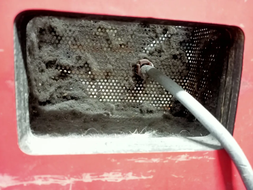
Dust accumulating on the air intake grille. Yuck!

Air movement inside the cabinet is not ideal, as the fans are trying to move air up and out, but the air has to move laterally across the cabinet floor to get under the board cages first. A better design would have been to have holes in the cabinet floor, so air could be entrained from under the cabinet, into the board stacks, and then out the top of the main tower. This is probably why Super System 22 boards have thermal issues, such as the ALTERA CPU on the video PCB, which tends to become thermally stressed and fail.
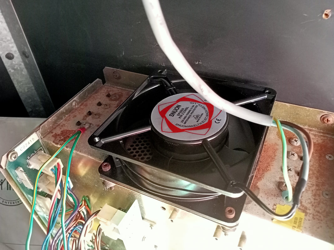
The fans in Super System 22 games live a hard life. They are huge fans that push a lot of air (probably because Namco realised how hot their boards get!). Of course, they eventually wear out and fail, especially if not cleaned regularly. The fans were all pretty old and grimy. I knew they were old because they were branded Dick Smith, and Dick Smith was out of business, and hadn't sold component fans for a long, long time even before it went bust!

Dick Smith rotary fan - a blast from the past!
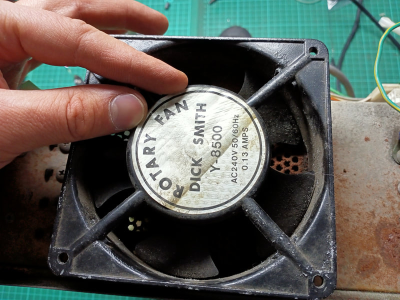
There are a lot of fans throughout the cabinet. One on each board cage, one in the lower section of the main tower, one at the top of the main tower, and one in the topper enclosure. One of the board cage fans wasn't working, one of the main tower fans was extremely noisy, and the fan in the topper enclosure also wasn't working. The other two appeared to be OK. So, I purchased three new ones to replace the dodgy ones. These fans are mains powered (240 VAC) and hook up to the mains supply cable routed throughout the main tower cabinet. Replacement fans are easy to get from a number of sources, but I bought some cheapies (eBay). The replacements need to be 120mm in length and width to fit the original bolt holes. The fan will have two wires; simply solder these to the active and neutral from the mains supply cable. The ground should be connected to the board stack cage (for the board cage fans), and to the fluorescent light fitting mounting bracket (for the topper fan).

New cooling fan installed on one of the board stack cages.
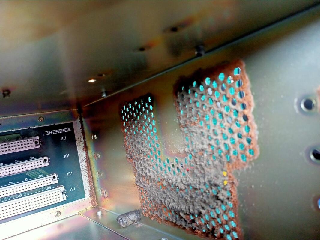
As an aside, there was evidence of corrosion within the cages, with rust having formed around the top (where the fan mounts) and bottom (adjacent the cabinet floor) of the cage. It wasn't causing any apparent issues, but evidence of corrosion like this doesn't bode well for the future of the boards; moisture is the worst enemy of electronics. I placed some desiccant packets (Bunnings) in the cabinet to make sure it stayed dry.

Rust in the board stack cages - a good indicator that you need to keep these cabinets dry.
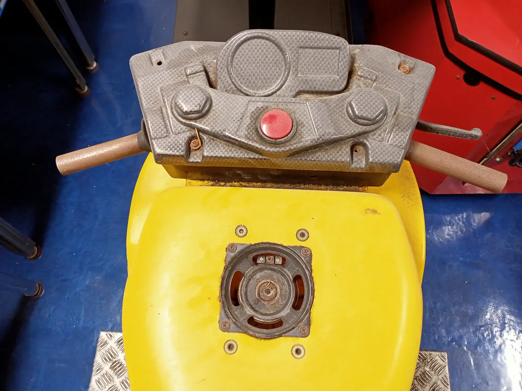
The speaker on this bike was completely missing its cone!

The fix for this was simple: replace the speaker. As luck would have it, I actually found an eBay listing where somebody was selling a number of spare speakers and plastic grilles. Brilliant! The only problem was that he was in the US, and wasn't willing to sell me a single speaker and grille on their own. I didn't want to pay $100 and end up with a bunch of spares I would not be able to get rid of, so I decided to find my own solution.
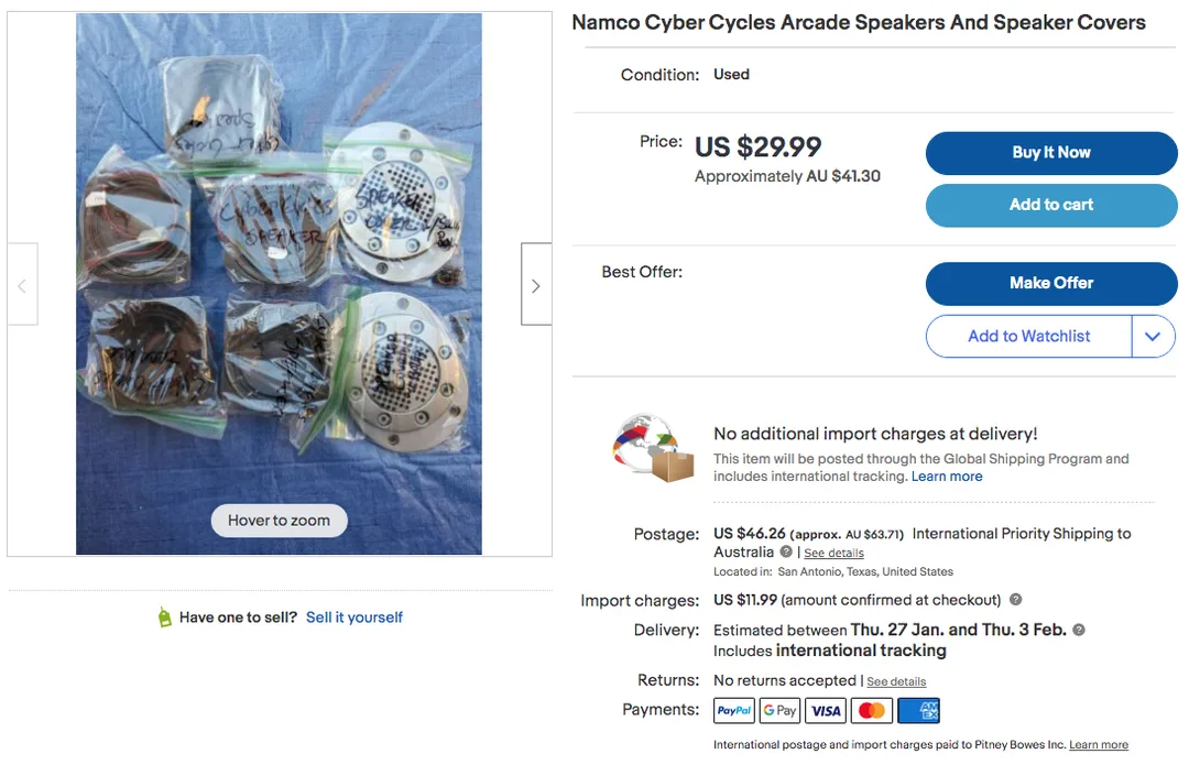
eBay listing for Cyber Cycles speakers and grilles.

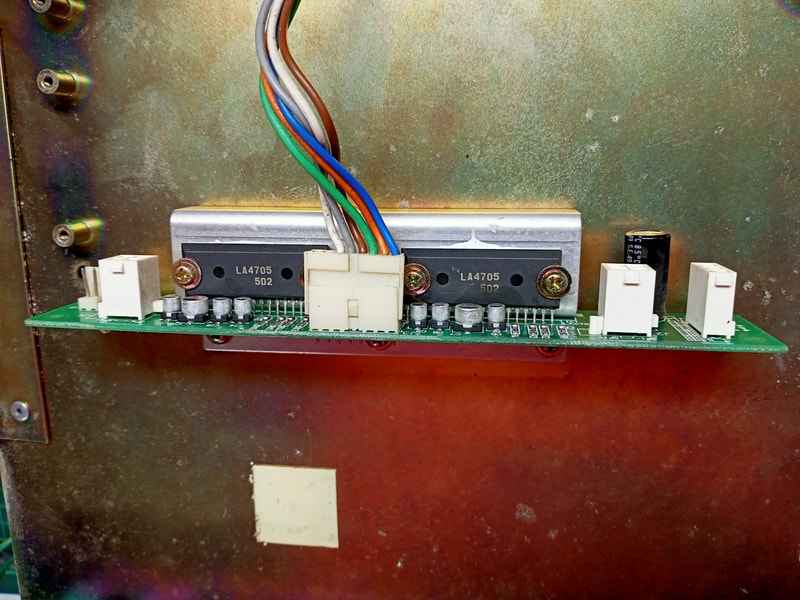
The speaker replacement was pretty straightforward. The original speaker specification is a 4 ohm and 40 watts, with a 4" (100mm) speaker cone. The LAI manual doesn't list the required speaker specifications at all, however a different version of the manual specifies a 20-watt speaker rating. For testing purposes, and in a pinch, you can use a general-purpose component speaker (Jaycar). The Jaycar speaker is rated at 4 ohm but only 2 watts. The problem with using a lower wattage than specified is that the amplifier may drive the speaker with too much power. This may be more than the speaker can handle, especially if the volume is turned right up, and "blow" the speaker. I used this 2-watter for some testing while I waited for a more compatible speaker (element14). This one had the same impedance (4 ohm), which is important to match as it affects the entire amplification circuit. I could not find a reasonably priced speaker with a similar wattage rating, however this one is 30 watt, which is quite close to the original 40 watt speaker. The datasheet for the amplifier (LA4705) specifies it is a 15-watt amplifier, which is well below the rating of the speaker in any case. A great primer on matching speakers to amplifiers is presented by Tony Dziedzic. It relates to replacing pinball speakers, but the guidance is equally applicable to arcade cabinet speakers.
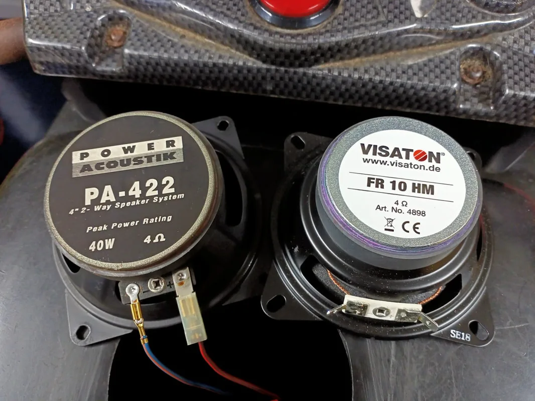
Original bike speaker on left, and compatible replacement on the right.

Once the speaker arrived and installed, it was a simple matter of hooking the wires up to it. I crimped some spade connectors onto the speaker wires, and attached them to the lugs of the speakers. The red wire goes to the positive speaker terminal, and the blue wire goes to the negative. I also made a makeshift replacement for the speaker grille, using a pinball speaker grille leftover from one of my restorations (part no. 545-5072-03, PSPA).
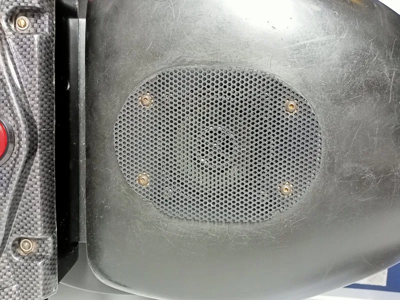
Replacement speaker grille cut to the size of the original plastic.
Once it was all wired up, I booted the game and started a game to test the sounds. Hmm... I could hear sound coming from the other bike, but not this one. I swapped the new speaker to the other side, unplugging the already-working speaker. The new speaker worked fine here! So why didn't it work on the other side? After some further investigation, I realised that the two speakers on the monitor pedestal weren't working either. There was no sound at all coming from one side of the cabinet. I was happy that the speakers were all wired correctly, so the problem lay elsewhere.

Slightly dodgy looking SMD capacitor at C7 on the amplifier board.
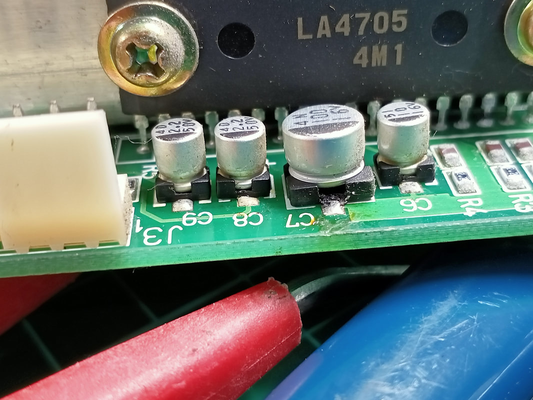
Replacement LA4705 amplifiers are relatively easy to get if you are happy to roll the dice with Chinese equipment pulls. I got lucky and ordered two from a Chinese supplier. They turned up as described and appeared to be unused, however they were likely pulled from another piece of equipment and cleaned. As I could not tell which of the amplifier chips was not working, I replaced both with the "new" amplifiers I received. That did the trick, and I now had sound from both sides of the cabinet! While I don't normally recommend buying dodgy chips off eBay, that was the only place I was able to find them on this occasion. Sometimes, we do what we have to do!

New amplifiers installed on amplifier board.
Now, onto the final sound issue. With the sounds apparently working on both sides of the cabinet, I noticed something unusual during attract mode. During attract mode, music plays while you watch bikes race through the two tracks in the game. In between, the title screen appears, and a voice says "Cyber Cycles; presented by Namco". You can hear what this sounds like in the video below.
While I could hear the music in attract mode play without issue, I only heard the "Cyber Cycles; presented by Namco" voice coming from one side of the cabinet. Weird! When I started a game, everything sounded normal, except for the voices. There were no voice callouts, announcements, or other spoken words coming from one side of the game. That meant that there was no "3, 2, 1" countdown at the start of the race, no sounds made by the bike rider, and no announcer voices during the race. All of the other sound effects seemed fine!
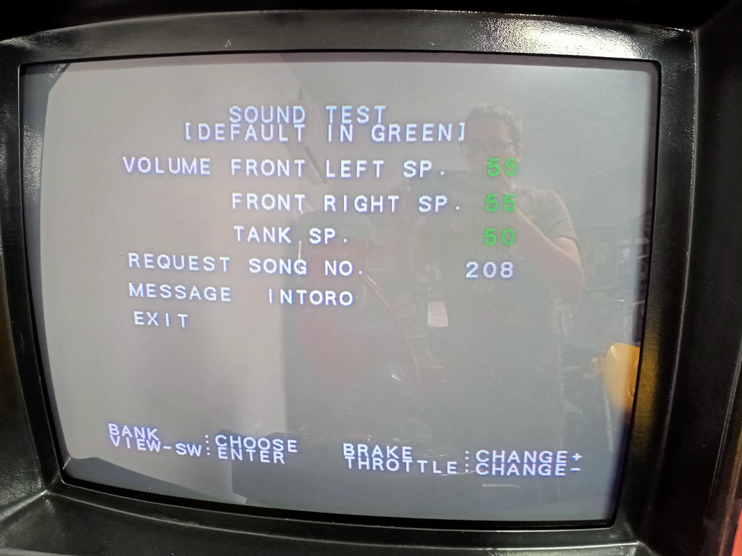
Whenever I get a weird issue such as this, I like to see if I can replicate it in test mode. Luckily, test mode has a comprehensive sound test option which allows you to play every single sound sample used in the game. You can scroll through each of them, including sound bytes in different languages (the game is available in both English and Japanese). I noticed that the problematic side was able to play most sounds except for the voice files. The voice files start at file number 208 (referred to as "songs" in the sound test menu), and none of them produced any sound at all.

Sound test menu showing the beginning of the voice files at song no. 208.
After swapping some boards around, I narrowed the issue down to the CPU board. I sent the CPU back to Joey at JOMAC to have a look at, and he mailed me back a working one. Top service! I'm not sure exactly what the issue was with the board, but all of the sound files played properly with the replacement.
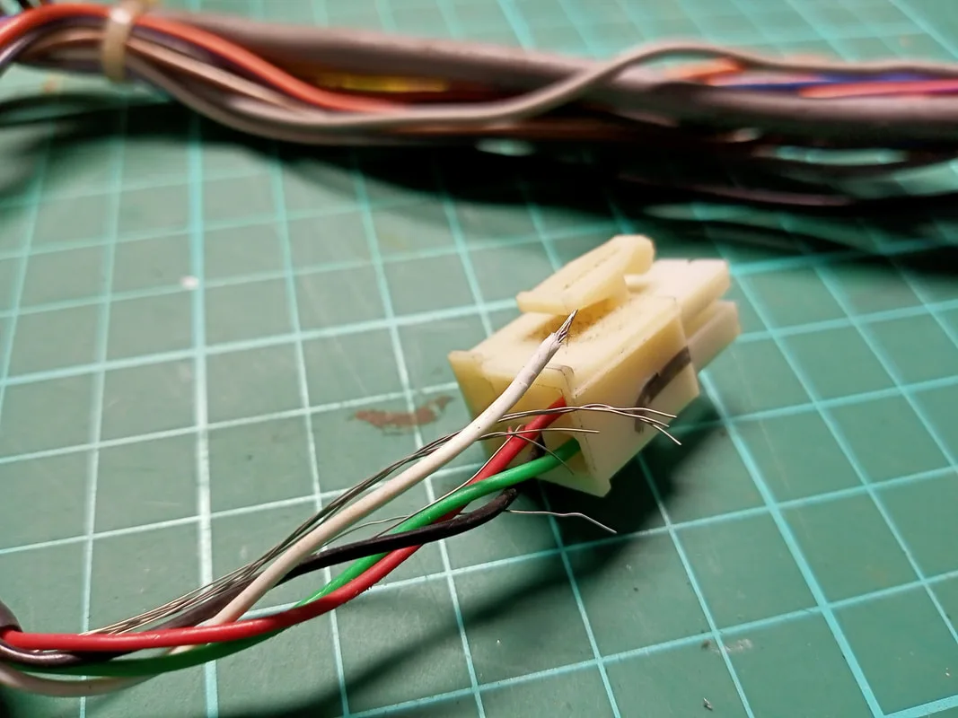
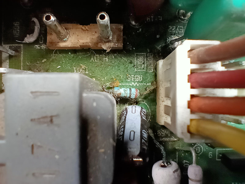
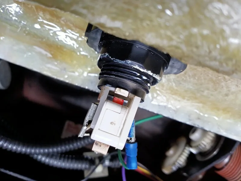
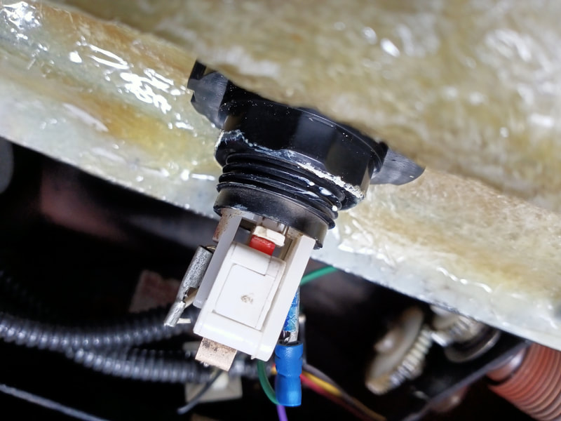
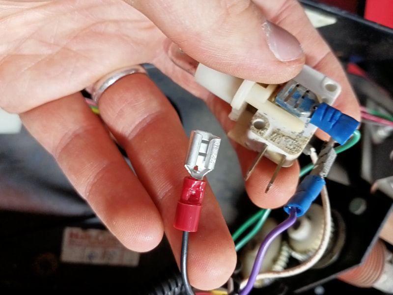
Loose white wire and uninsulated conductors.

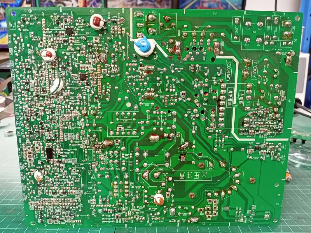
It took me a while to figure out the correct type of crimp pins to order that were compatible with the male pins on the board. The crimp pins and connectors used by Namco in these connectors would appear to be compatible with MATE-N-LOK style connectors made by TE Connectivity. However, I haven't purchased any replacement connectors to verify this.
Female crimp pins (element14) are needed for the male plastic connector housing. I ordered a few of these, stripped the wires back, and crimped them back on. Good as new. Note that this board is unlabelled on the schematics in the manual, but can be identified by the wire colours and the "ring" identifiers.
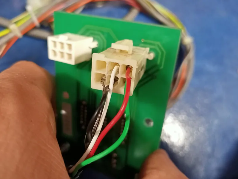
Connector after repairs to wires.

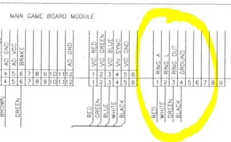
Identification of the link board in game schematics.


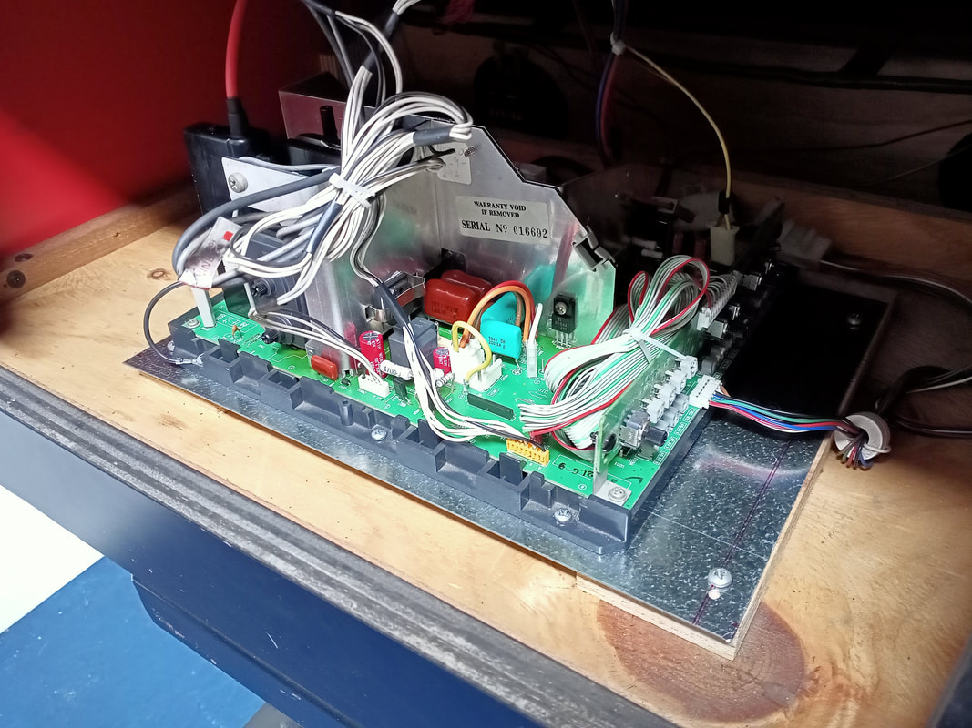
Board cage sitting on original timber mounting plate.
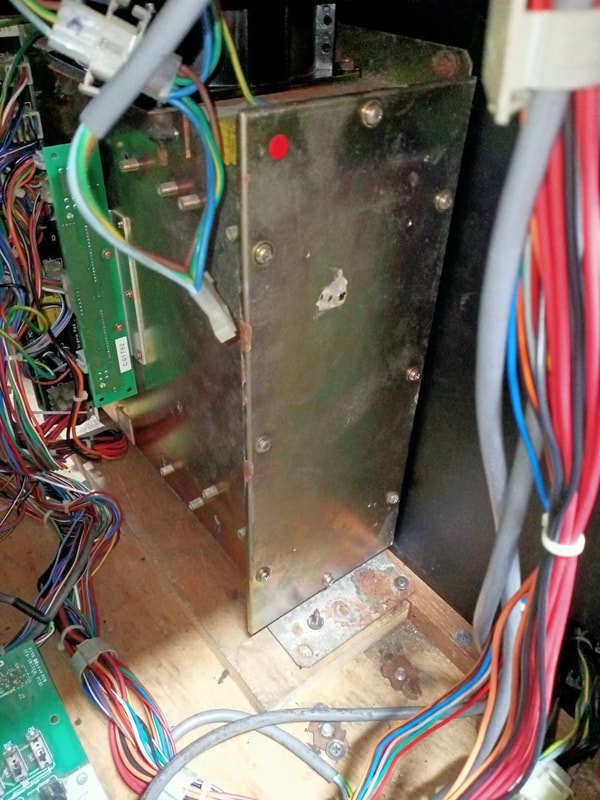
I have no idea how the timber disappeared from the other side of the cabinet, but it did. These timber platforms are about 2cm high, so some standard lengths of pine, cut to size, are perfect replacements (Bunnings). I followed up with liquid nails (Bunnings) and left everything to sit overnight with a weight on top. Then, the board stack cage went on top, and got screwed into place. The screws secure the board cage to the base of the cabinet as well as the side panel.
Gluing the timber into place.
Final positioning of the board cage before driving the screws in.

Cleaning the gunge out of the handlebar assembly.

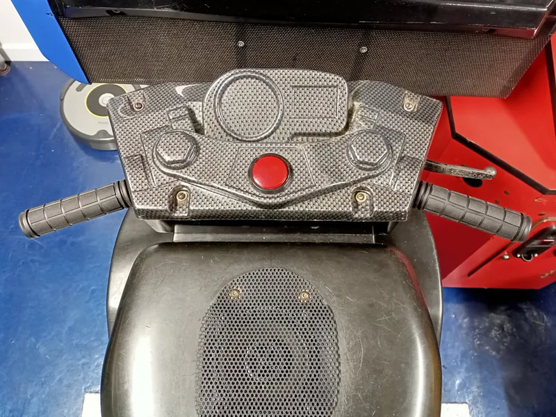
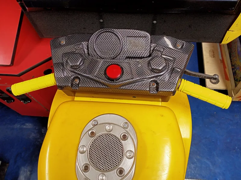
The next couple of issues were related to the view change button; the large red button in the centre of the handlebar assembly. The button was not lighting up on one of the bikes. First step was to open up the handlebar assembly and take a look. Four machine screws secure it to the bike.
Opening the handlebar assembly.

The issue of the lamp was easily fixed by replacing the bulb; the original incandescent had long since burned out. The bulbs used here are 12-volt #555 style bulbs.

Blown lamp in the view change button assembly.
View change button lamp working again.

The next issue was with the view change switch on the other bike. The lamp worked fine in this button assembly, but the switch did not, and it wouldn't register. Triggering the switch actuator manually with my finger proved that the switch actually worked, and the problem was with the button itself. Looking at the assembly from the underside, I noticed that the button actuator would not travel far enough to actually actuate the switch. The switch actuator on this switch was quite stiff, and required a lot of force (and maximum travel) to be pressed down. The simplest solution here was simply to change the switch for one with a "softer" actuator that activated more easily.
Switch actuator with the button in its resting state.

Switch actuator with button fully depressed, but the actuator remains "unactuated".
Of course, as I was fiddling around with the new view change switch, I ended up breaking it in a different way by snapping one of the wires from one of the lamp crimp terminals. The wire was stripped and a new crimp terminal (Jaycar) was installed. Good to go again!

New switch crimp terminal installed.
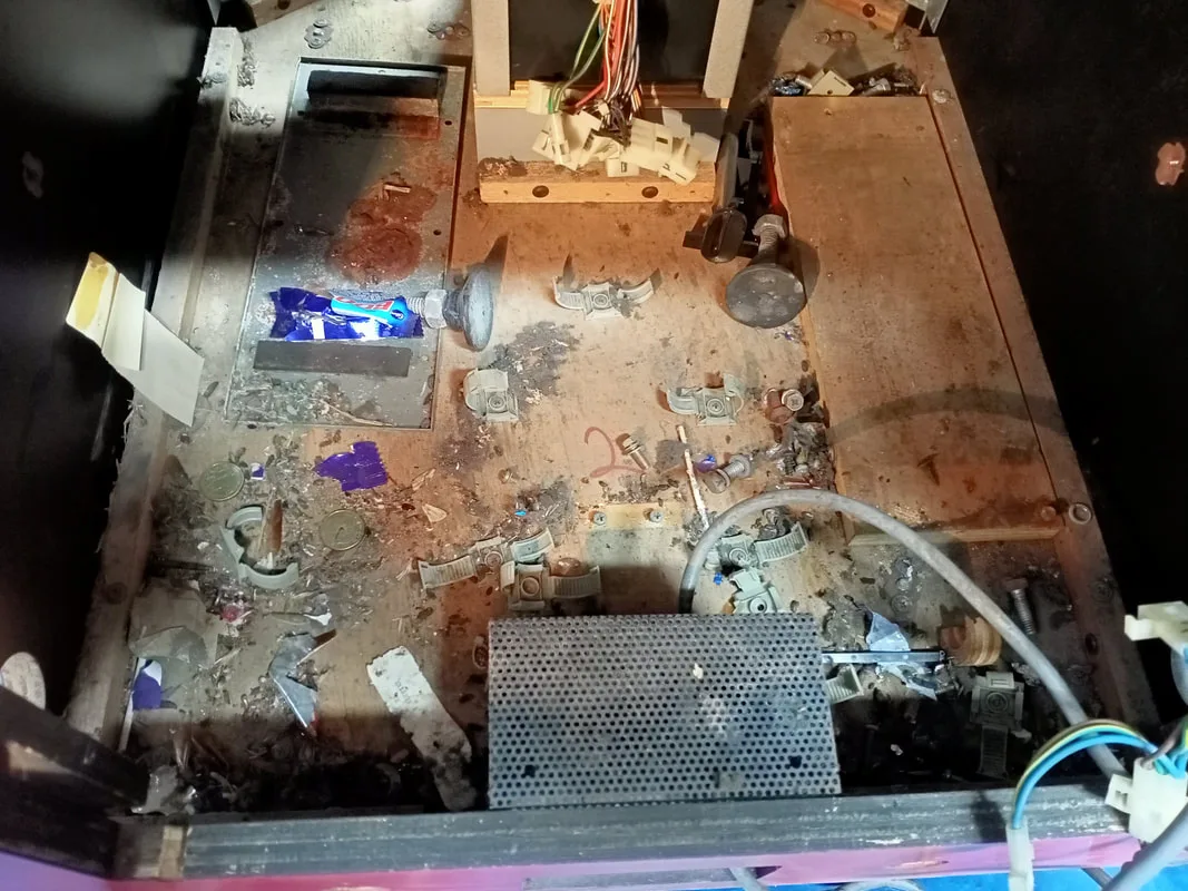
Cabinet interior after removing the board cages.

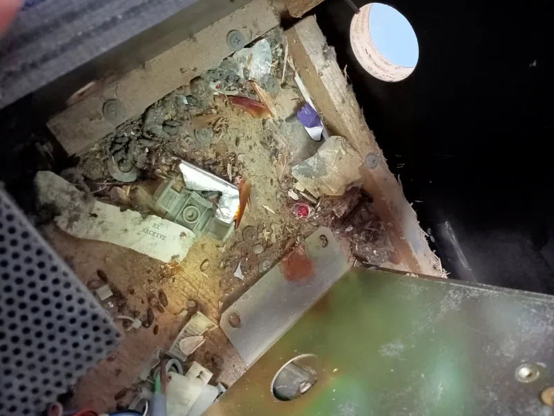
Rat poop - yummy!


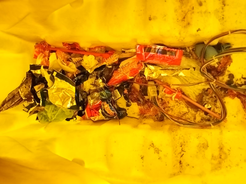
Rubbish inside the yellow bike.
The cabinet of any game is usually a treasure trove of parts, too. Screws, bolts, nuts, fasteners, and other useful bits dropped here over the decades are always worth keeping. I found a bunch of things inside this cabinet, most of which I found homes for and ended up using to finish off repairs elsewhere in the cabinet.

Parts recovered from inside the cabinet.
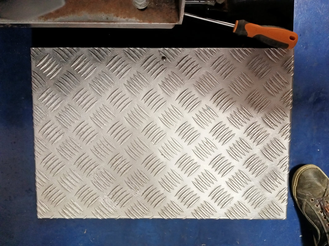
One area in particular which needed a lot of cleaning was the checker plate platform on either side of the bikes. This stuff gets dirt and grease driven into it by everyone's' shoes, so over the course of years it develops a thick, greasy, dirty film which is really hard to get off. This needed a hard bristle brush, some degreaser, and a lot of elbow grease to get it looking like new again. And then it shone like new!

Dirty, grimy checker plate platform.
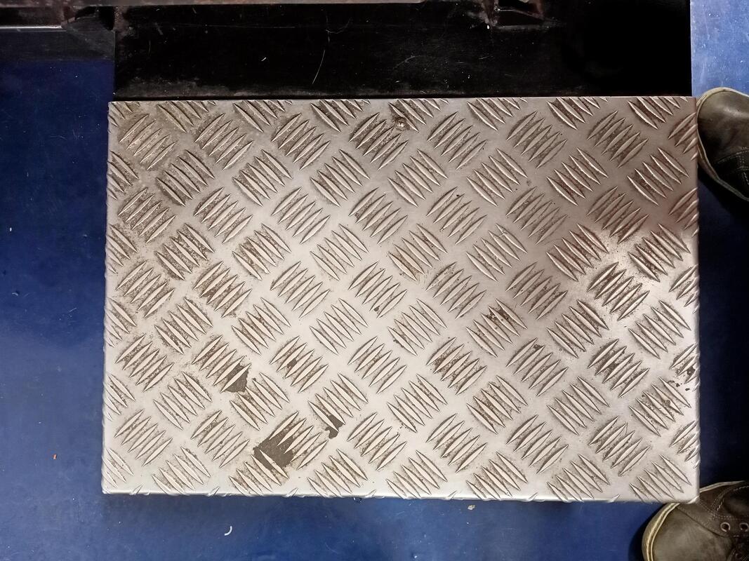

Nice and clean after some elbow grease!
The next part of the cabinet which needed attention was the monitor pedestal. The thing was dusty inside and out, so a good vacuum and clean with detergent got it looking good again. It always amazes me how people leave adhesive tape residues all over the monitors. It disrupts your view so you can't see behind it properly! Be careful when wiping the front surface of a monitor, and only use a damp cloth. Don't use aggressive solvents, as these will damage the protective film covering the monitor.
Dirty and dusty.
All clean and shiny!

The metal speaker grille was in bad shape on one of the monitor stands, too. Looked like somebody had punched it, or it had an accident when being moved. It had a dent on one side which was quite noticeable. I straightened it out using a vice and a small mallet to bang it back into shape.

Bent metal speaker grille.
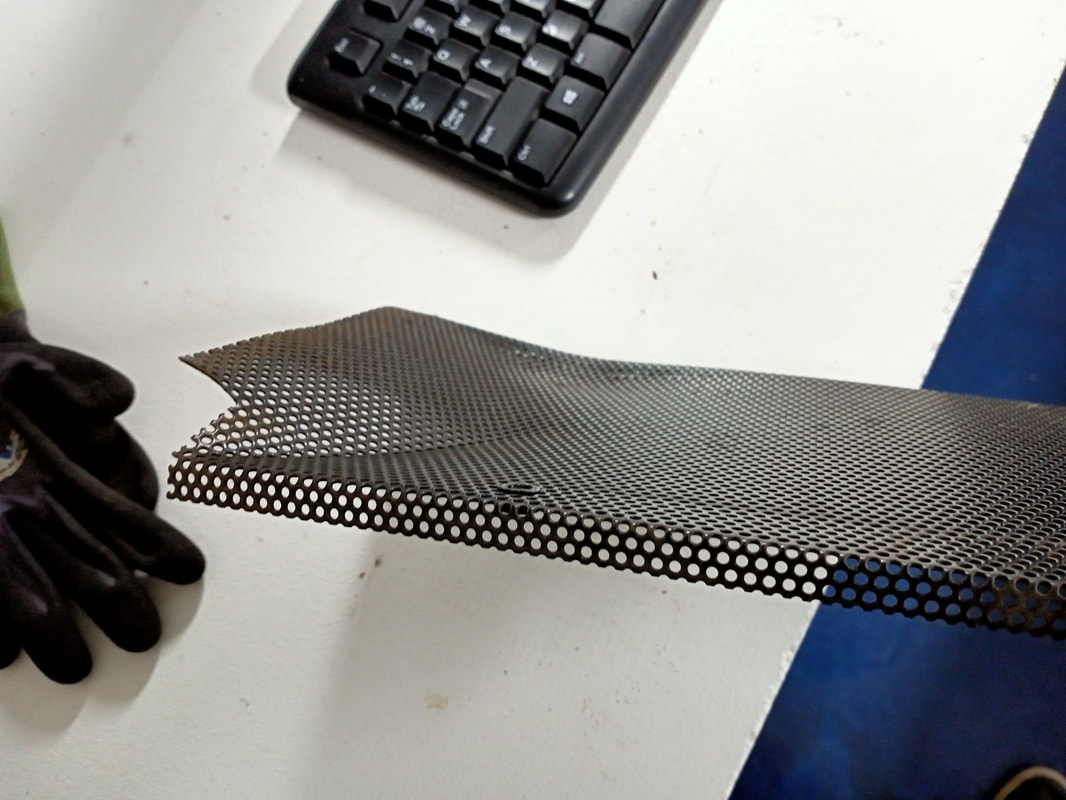
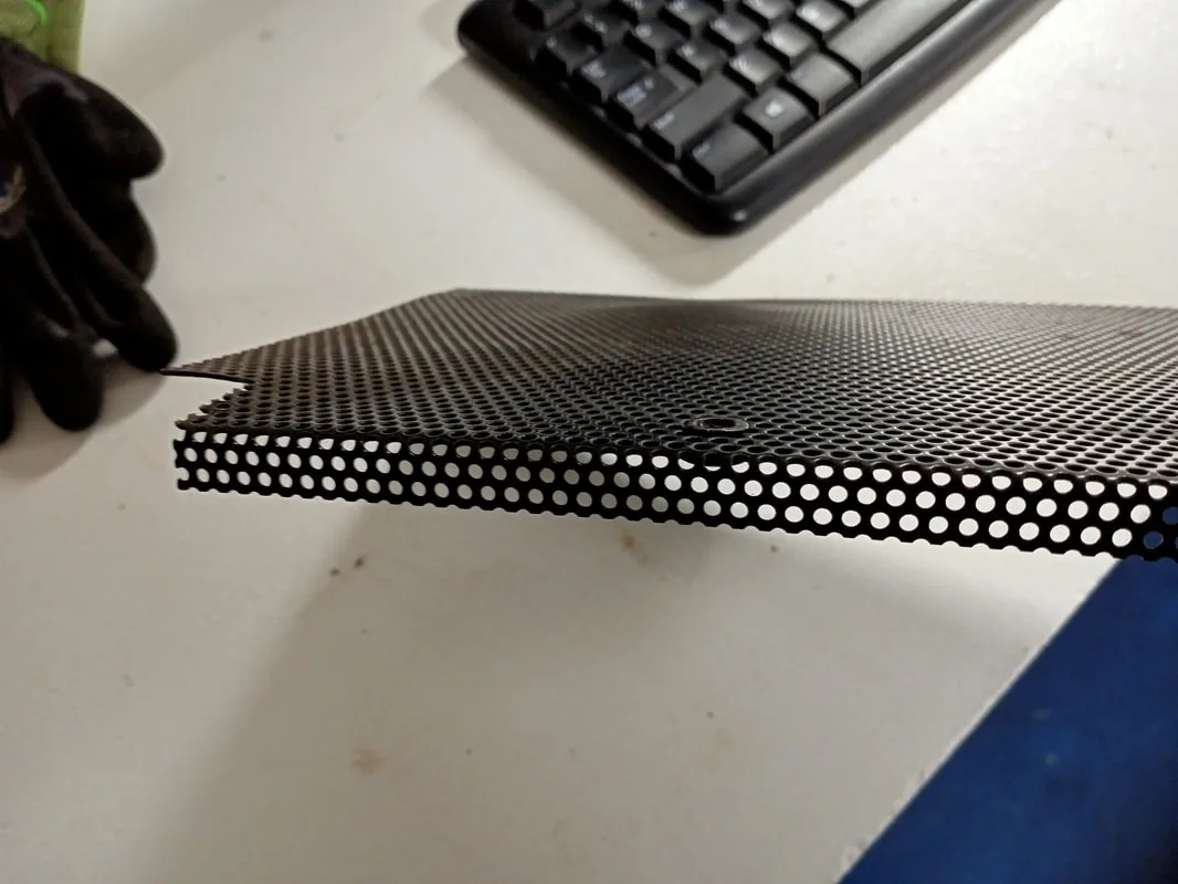
Flattened out to its original shape.

Reassembly
There aren't too many things to take apart on Cyber Cycles, so putting things back together isn't too much of a big deal. Again, the manual is a helpful guide as to how things are connected, and lists the type of bolts and nuts you need to do so. The bolts connecting the bikes, the monitor pedestals, and the central tower together are the same (M8 gauge from memory). I needed to replace a fair few as the original ones were missing or stripped.
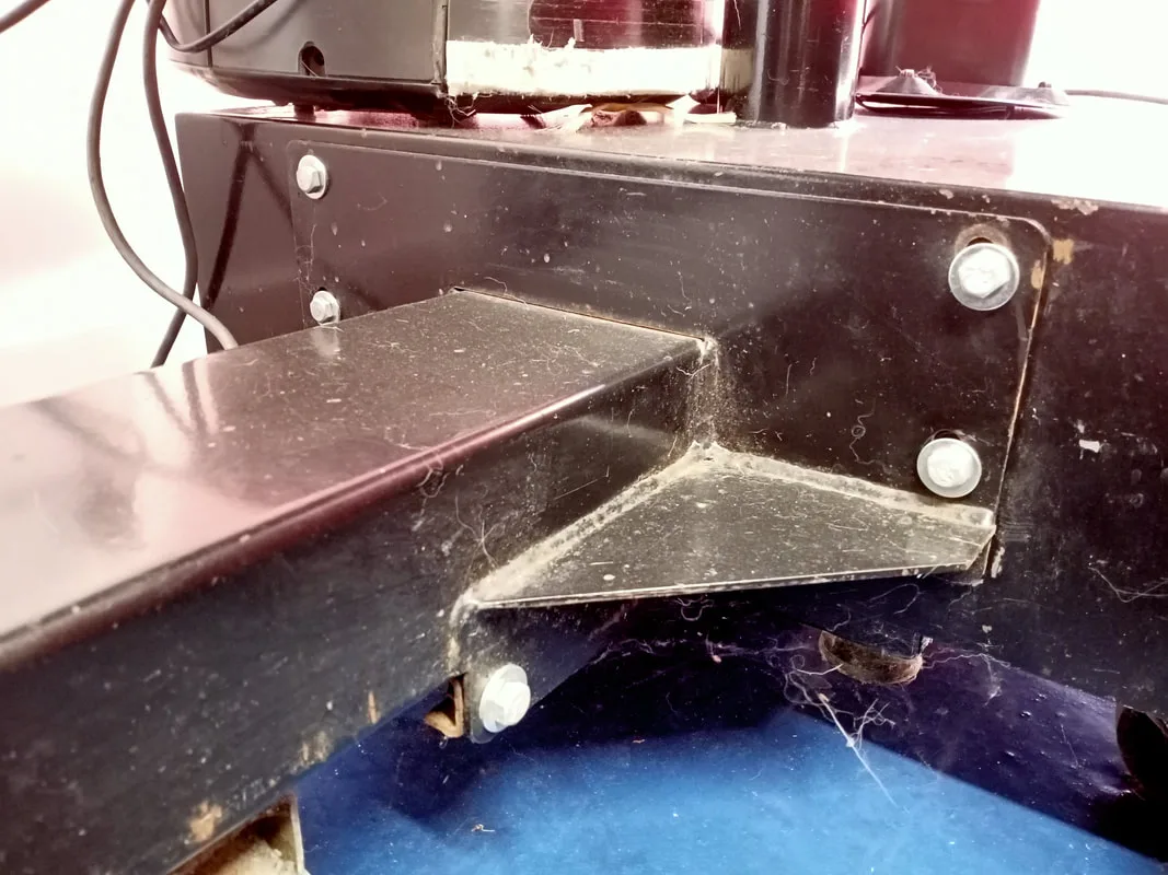
Bolts connecting the bike assembly to the monitor pedestal.

Unfortunately there were some parts I wasn't able to source for this game. For example, the bikes have plastic sides which sit at the base on the bike. All four of these were missing on my machine, and unless you have a spare cabinet to raid for parts, you're out of luck! Another part was missing on one of the bikes in this area. That was the metal cover for the connector at the base of the bike. One of these can be fabricated with a little effort, but I didn't bother in this case. Otherwise, the machine was intact, so there was nothing else to do.
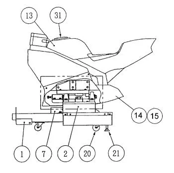
Missing parts were No. 7 and No. 14. Image from the Cyber Cycles manual.

Conclusion
This machine took a lot longer to repair than I thought it would. It was a huge learning experience as I hadn't had to delve into arcade repairs this much before. Sure, I had a Daytona USA (Sega, 1994) with issues, but I had fixed some of the minor stuff and it otherwise booted and played, so I hadn't needed to tear it apart completely. I'd also just acquired a Sega Rally Championship (Sega, 1995), but that was a basket case I wasn't ready to tackle yet. In fact, this machine was a good introduction to repairing arcades which will come in handy when I decide to tear into the Daytona and Sega Rally (watch this space).
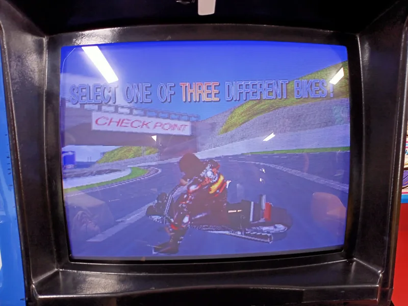
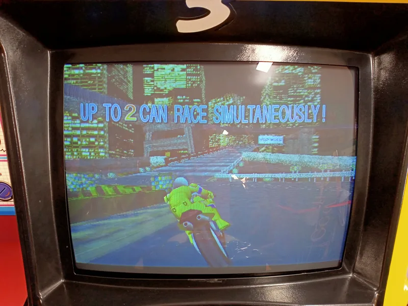
It was interesting to see how Namco designed their games, as it is a little different to the likes of Sega, and other manufacturers. The game itself is usually going to be compared to Sega's Manx TT Superbike (1995), which was released the same year, and was arguably a more popular game at the time. While Manx TT has two tracks (both of which share a stretch of track), Cyber Cycles has two completely different tracks to choose from, and three bikes.
Each have their own handling style and take a little while to get used to. The bikes tilt side-to-side on a horizontal axis, so you need to move your whole body to turn the bike left or right. This can actually be a pretty full-on workout if you race all afternoon, as your leg muscles take a beating! That's especially true if you're racing with the Wild Hog bike, as you need to turn fully into corners to pull off a drift.
Overall this was a long but worthwhile restoration. I learned a lot about arcade monitors in particular, and if nothing else, I learned how to properly remove and reinstall a monitor chassis. However, the Super System 22 board set remains a bit of a mystery to me, with so little information available in terms of troubleshooting and schematics. This is something I'm keen to learn a little more about if I have the time, and someone with expertise to lean on. Below are some images and video of the final product; hopefully they do the time spent on it justice!
Congratulations! It's a fun game. Let me know if you have any issues!