|
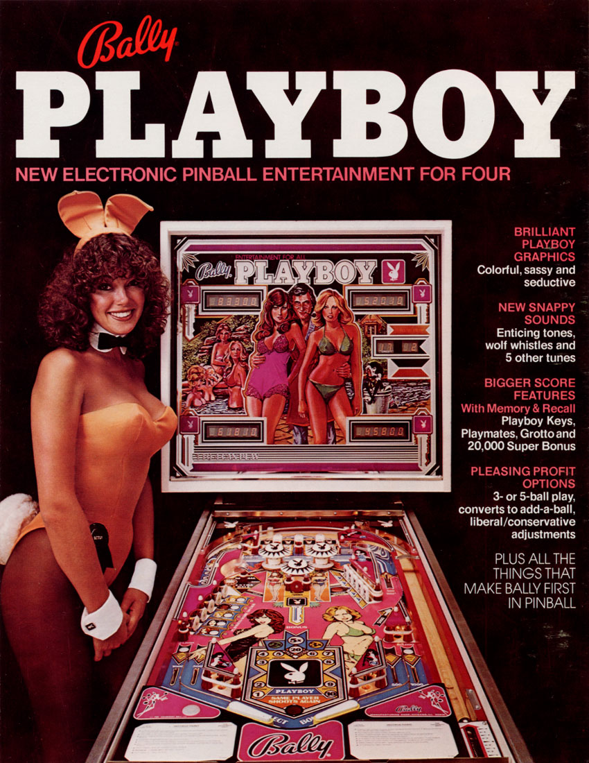
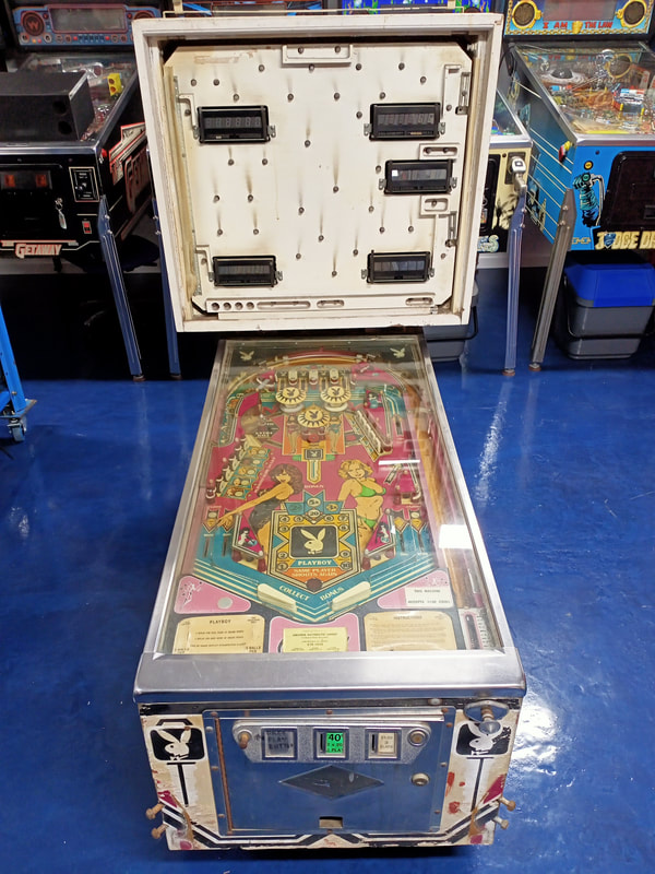
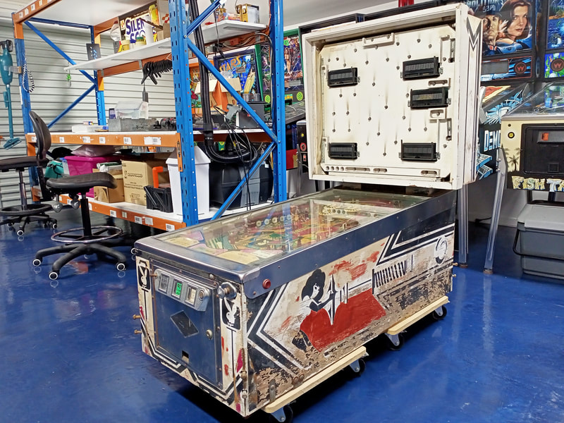
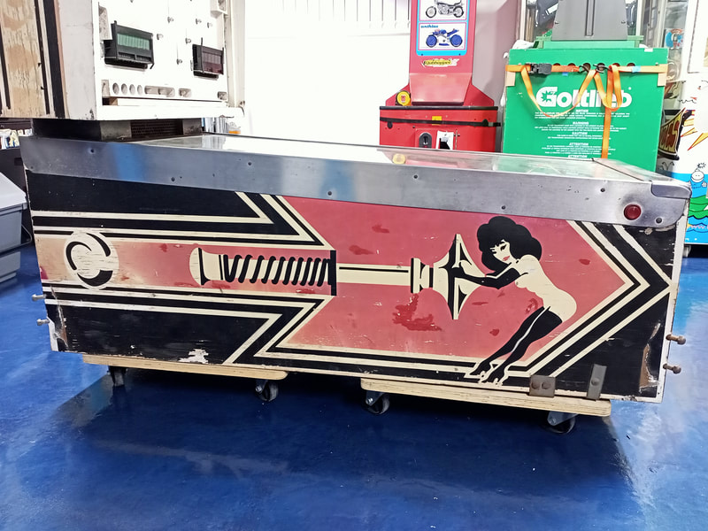
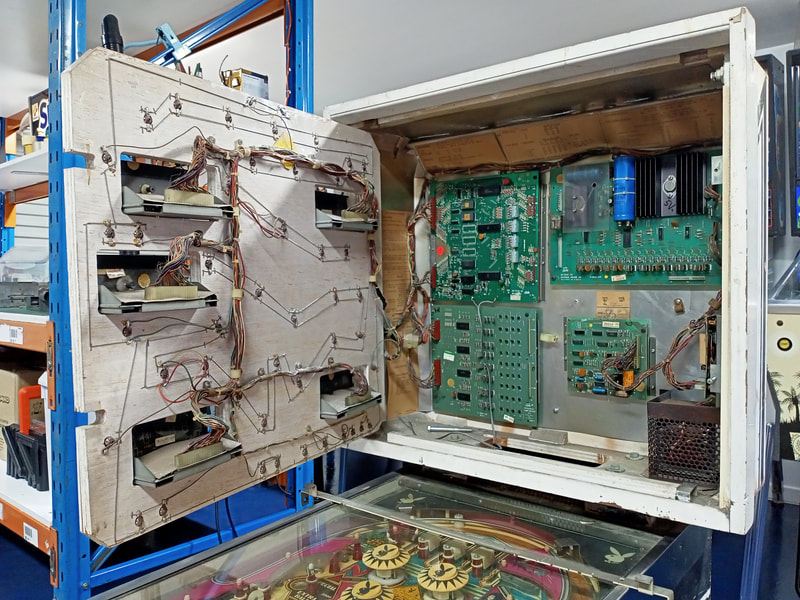
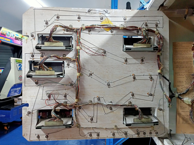
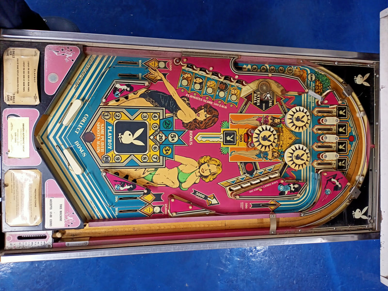
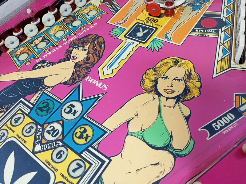
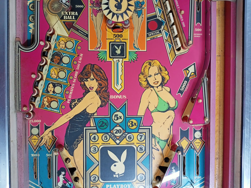
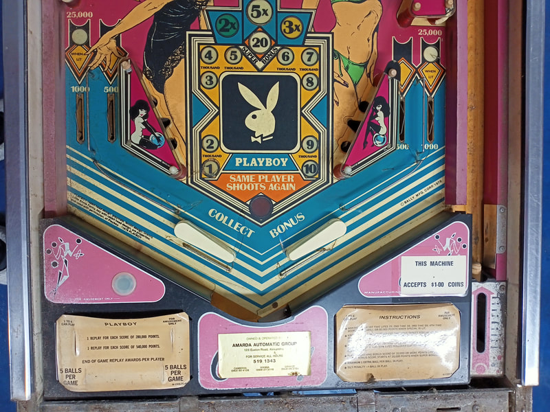
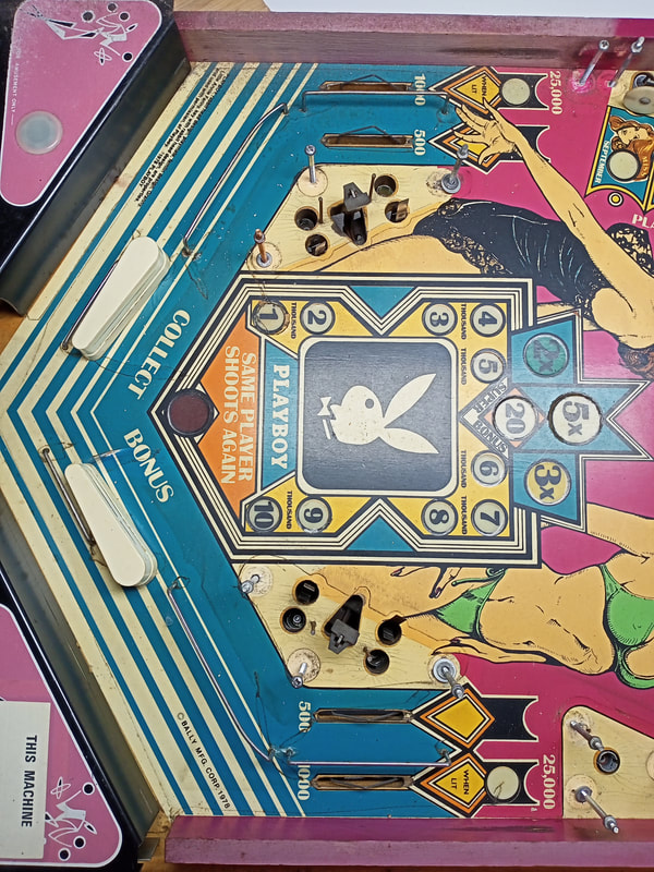
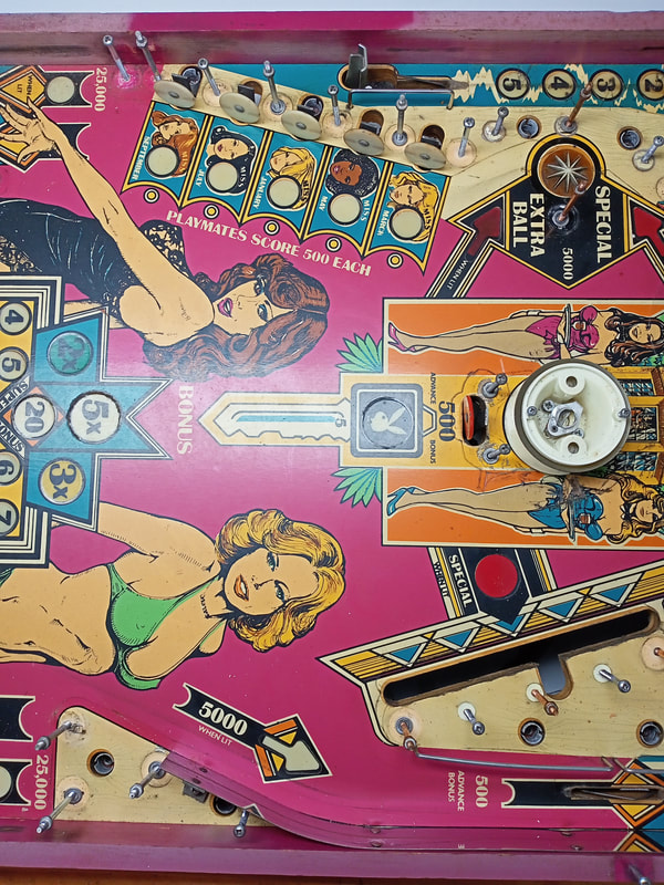
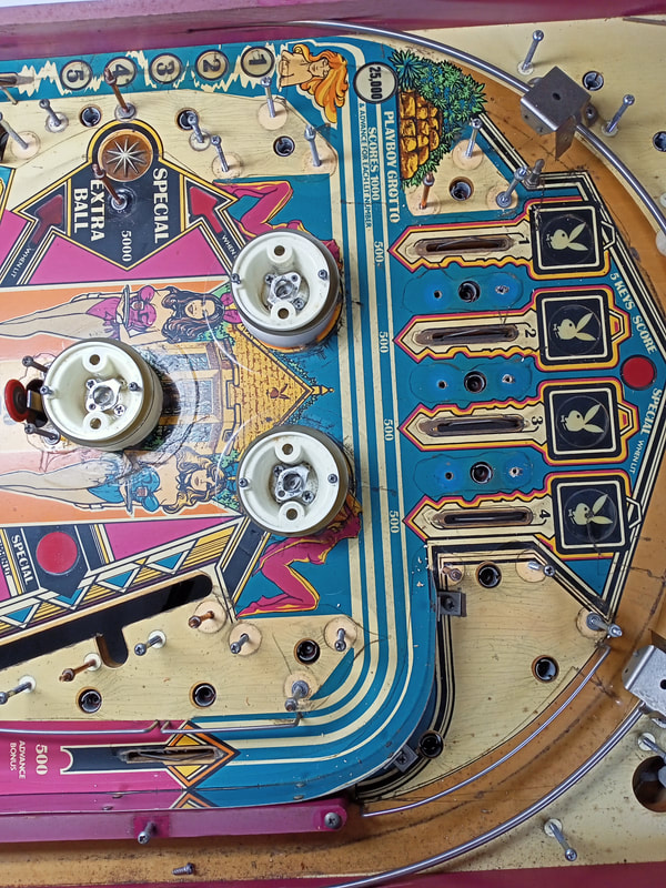
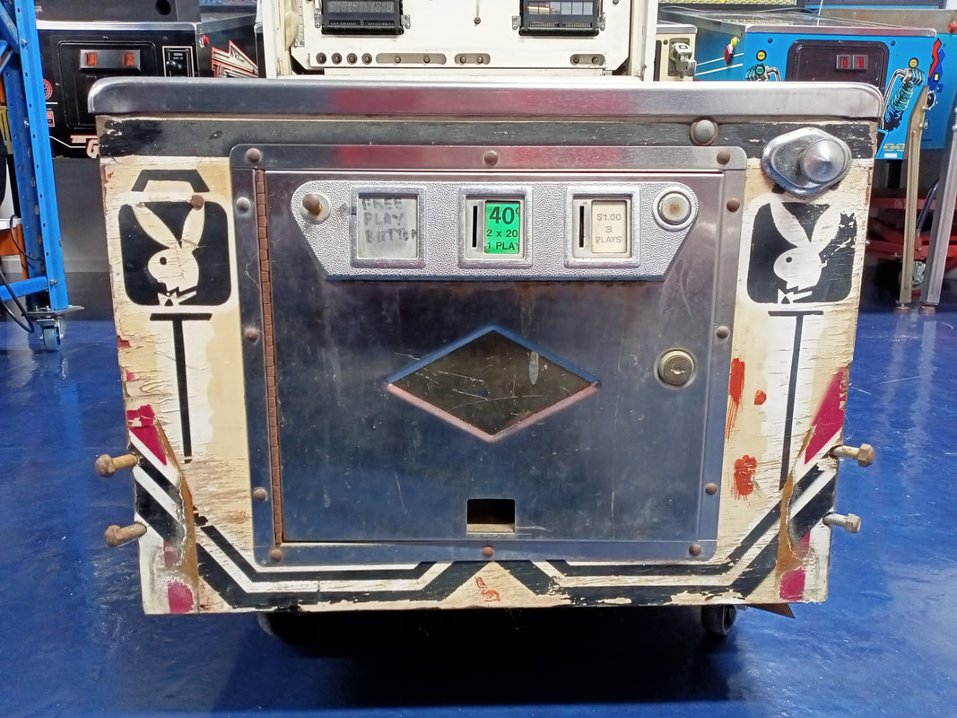
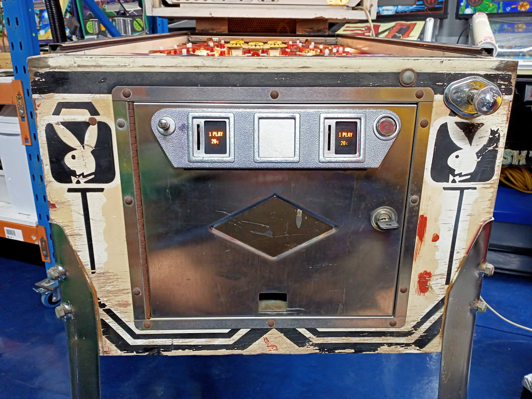
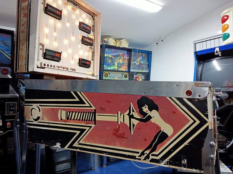
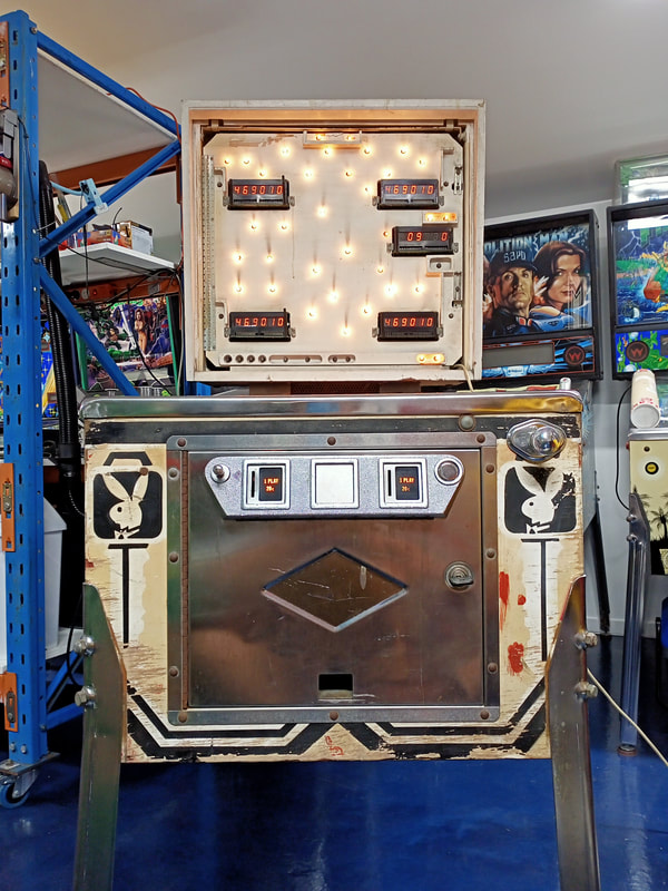
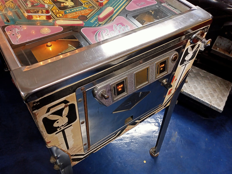
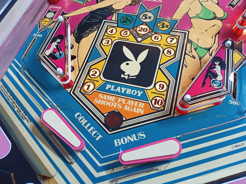
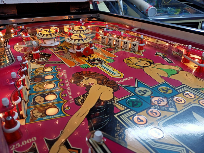
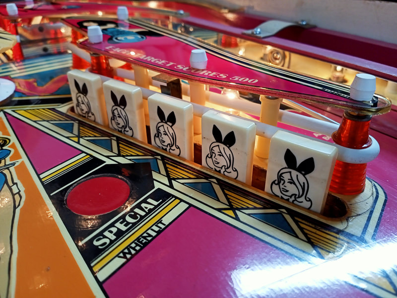
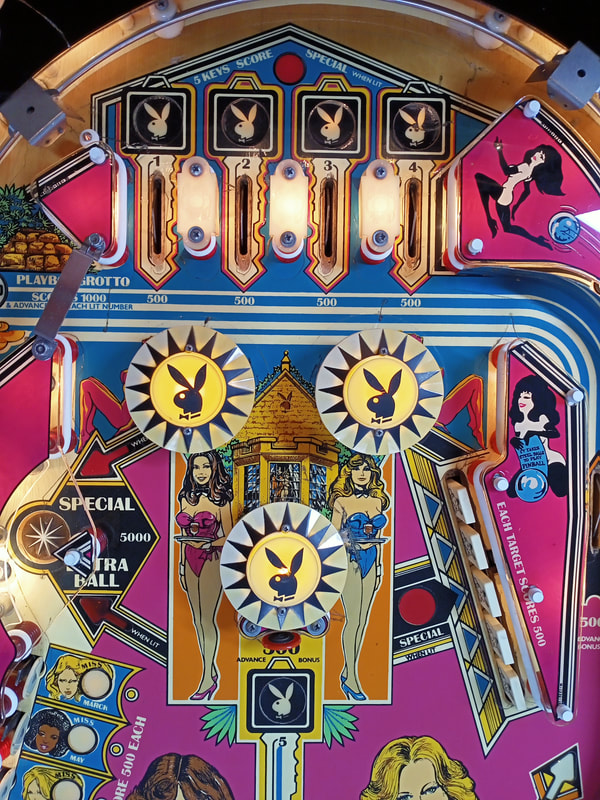
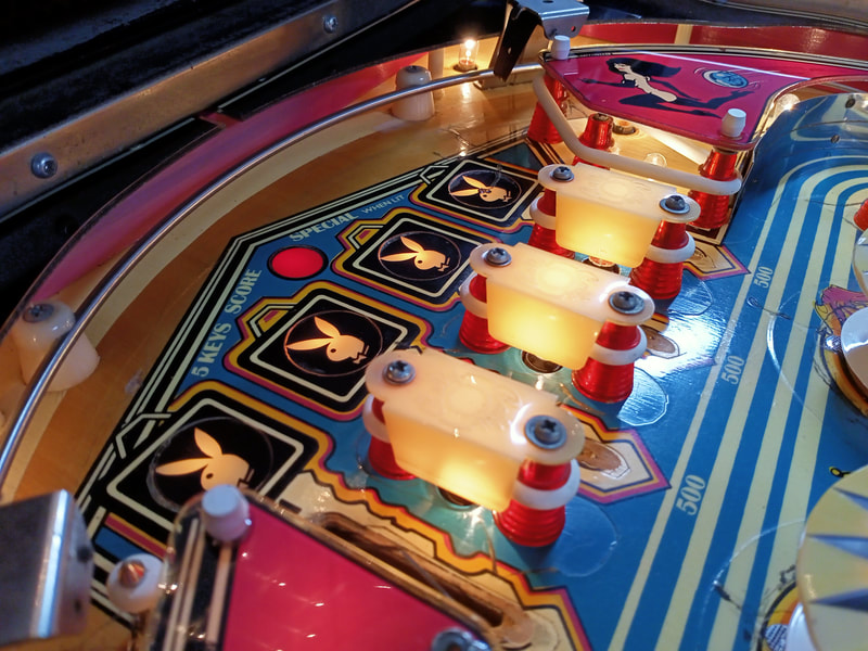
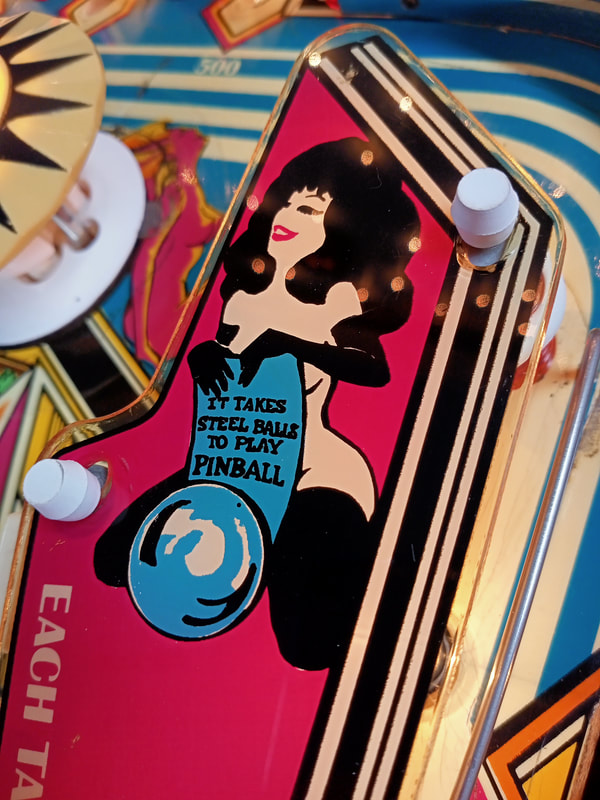
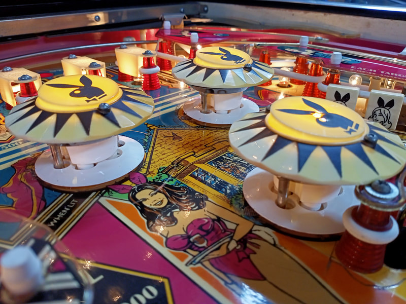
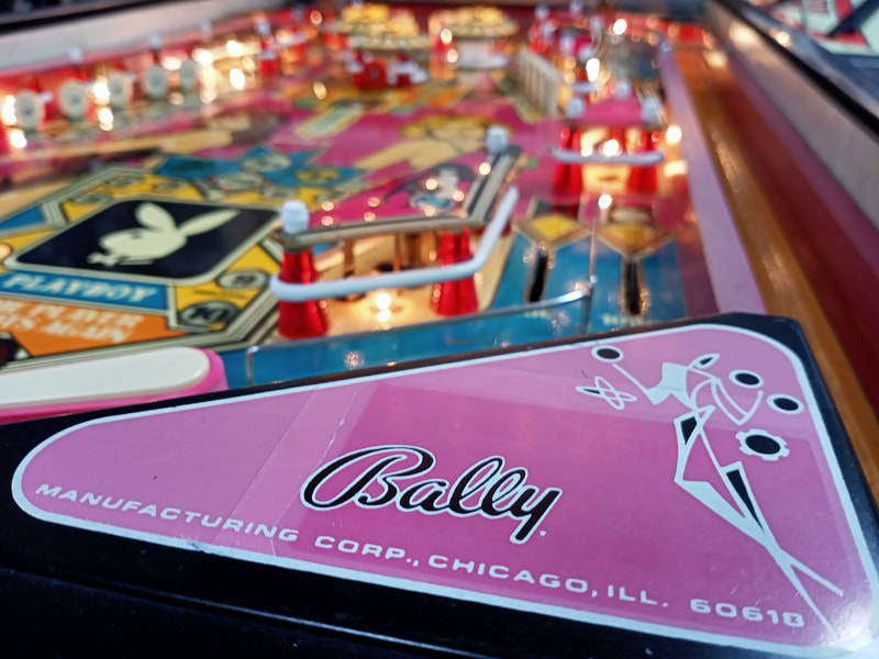
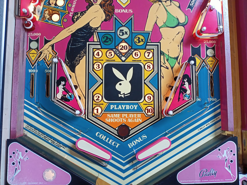
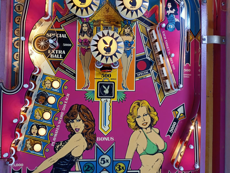
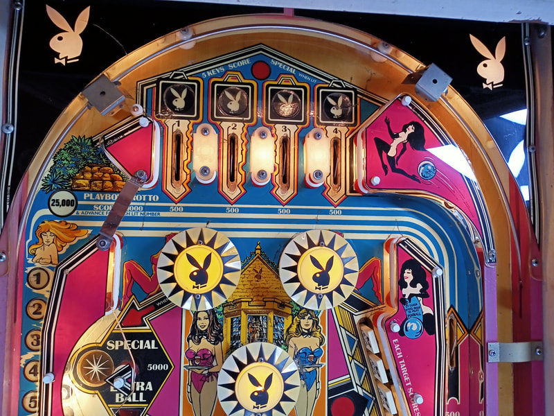
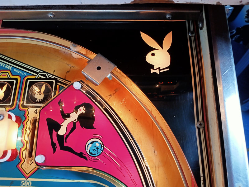
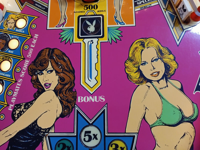
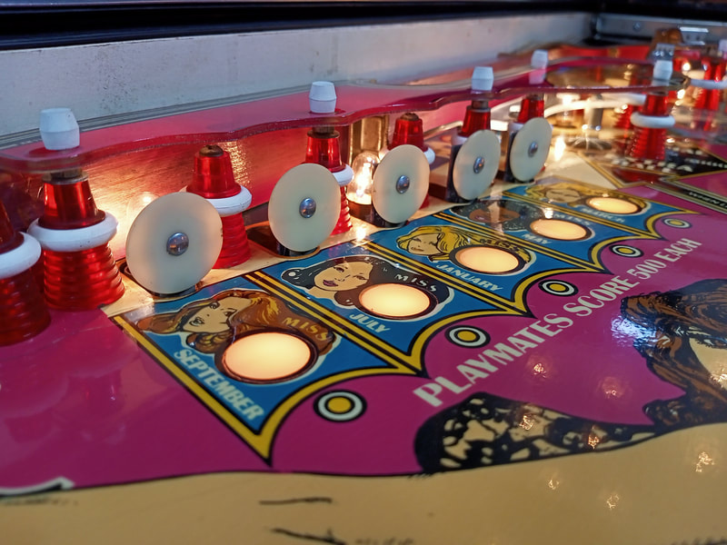
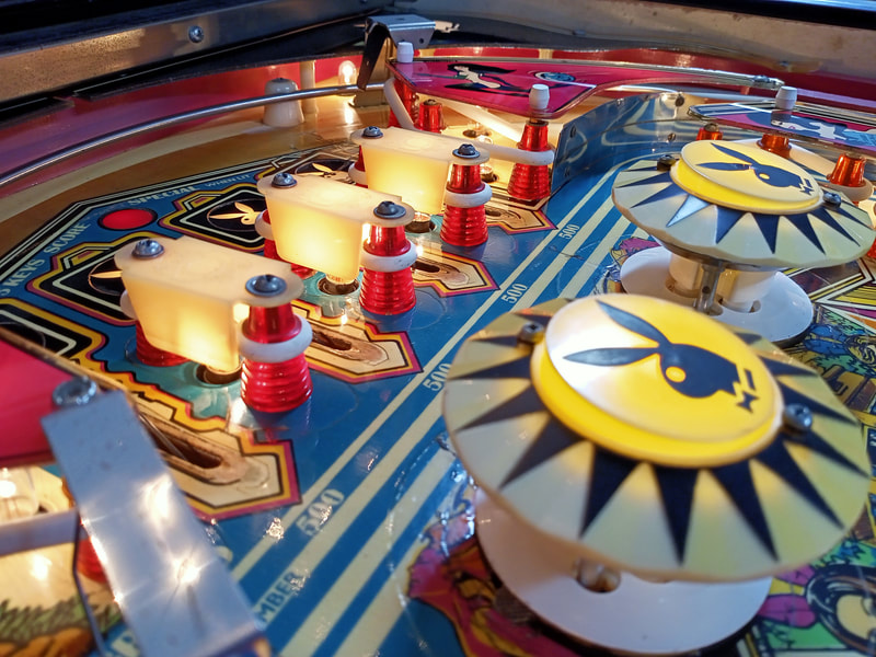
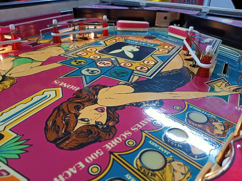
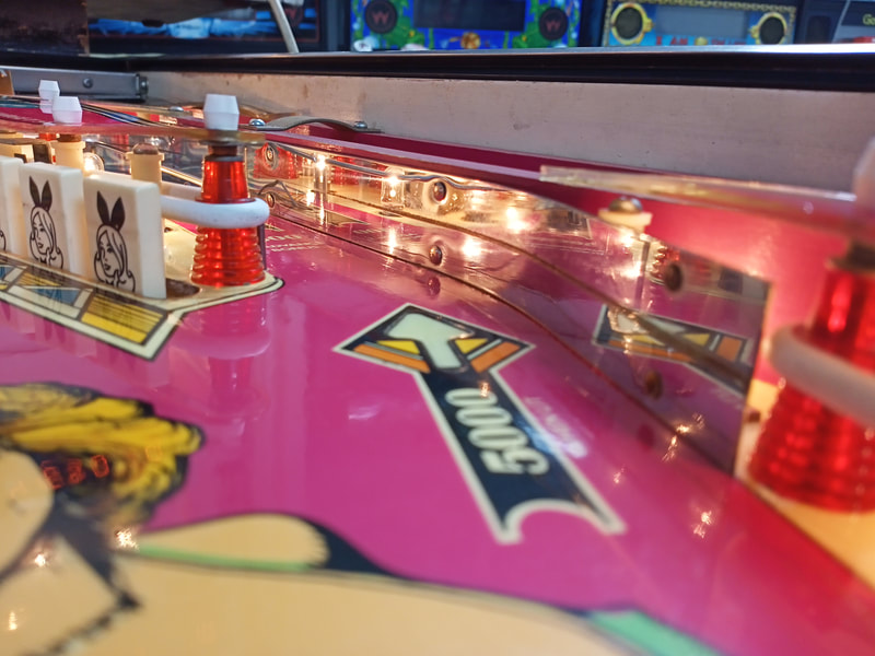
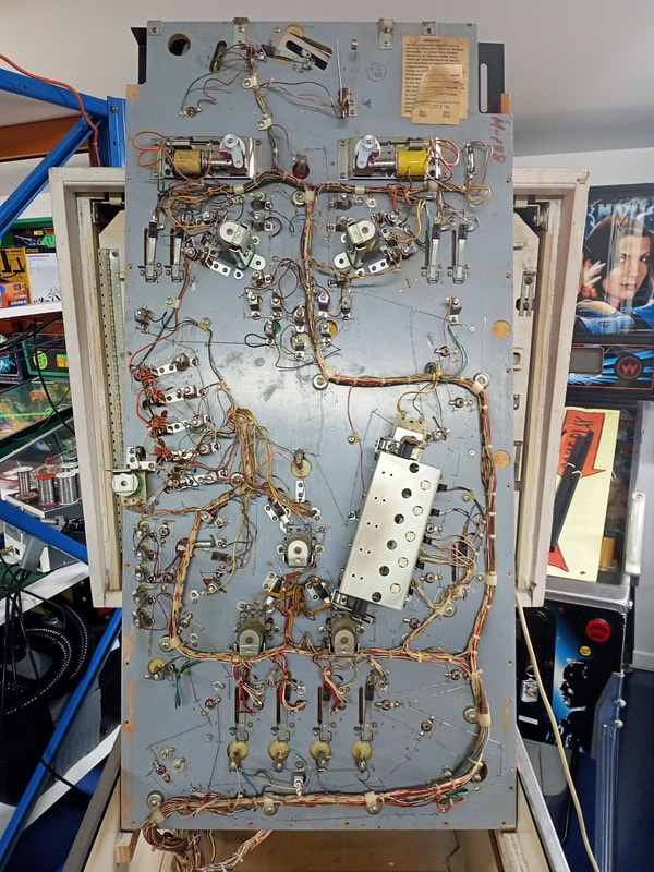
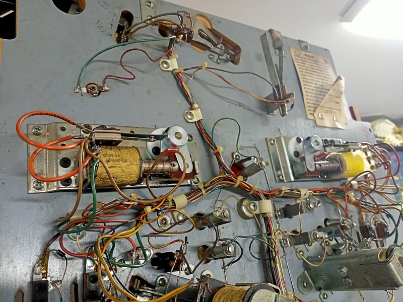
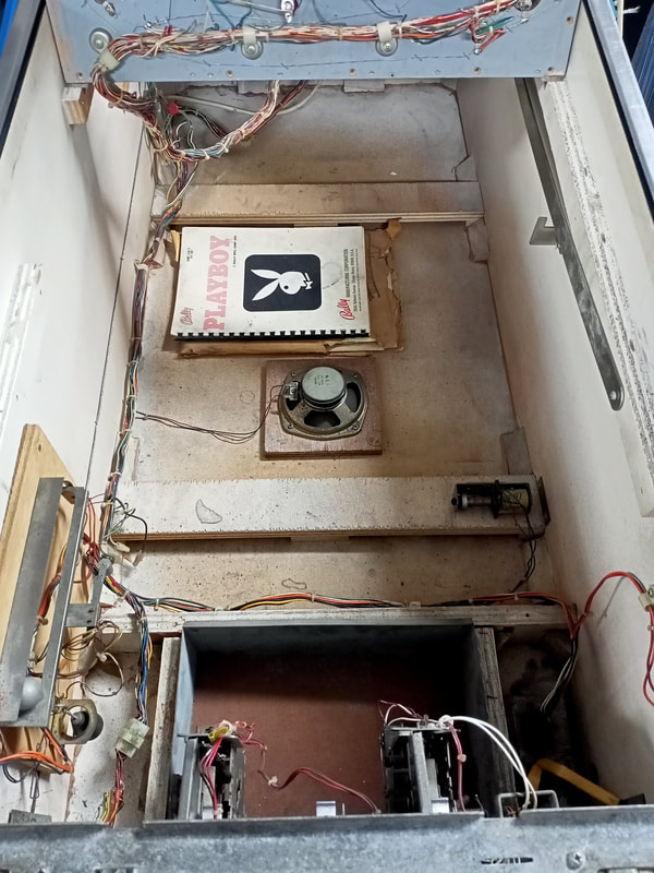
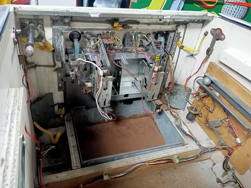
If you ever need proof that pinball was made for adolescent men, look no further than Playboy (Bally, 1978). As gaudy as this theme seems now, it remains a great example of a classic Bally game. There is a reason they made over 18,000 of these - they were fun! The standup targets on one side coupled with the drop targets on the other side made this a fun shooting game. This game was given to me to repair by an elderly customer who had stored it outside in his pergola for many, many years. I initially attended his house for a service call, but was then advised that he wanted the machine to be refurbished and brought back to playing condition. However, this customer did not want to spend a huge amount on the game, so I had to tackle this repair with budget in mind. Initial condition report (click on sections below to view details) Cabinet
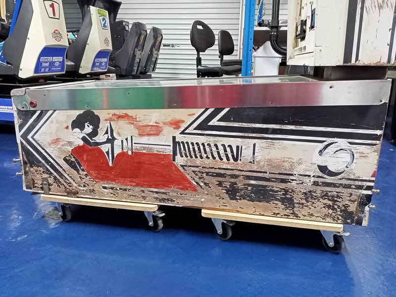
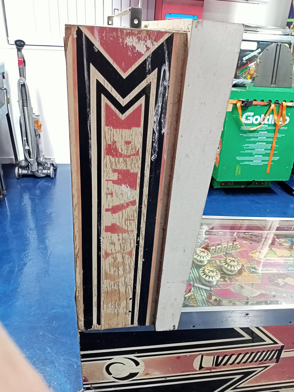
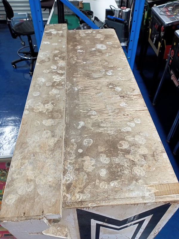
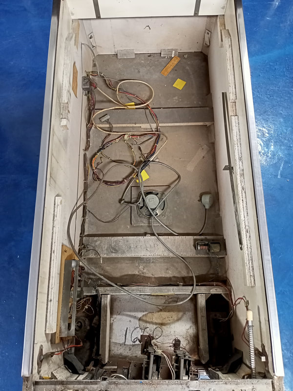
Poor condition overall.
Above playfield
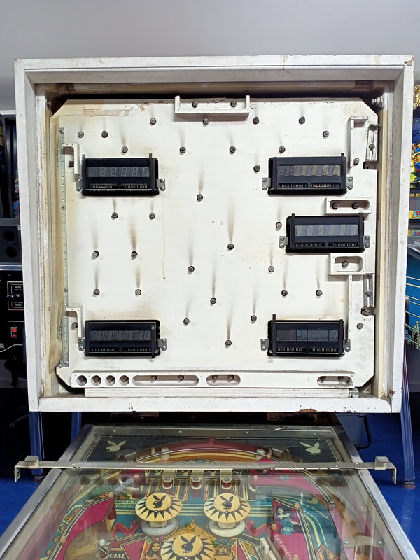
Poor condition overall.
Under playfield
Average condition overall.
Electrical
Good condition overall.
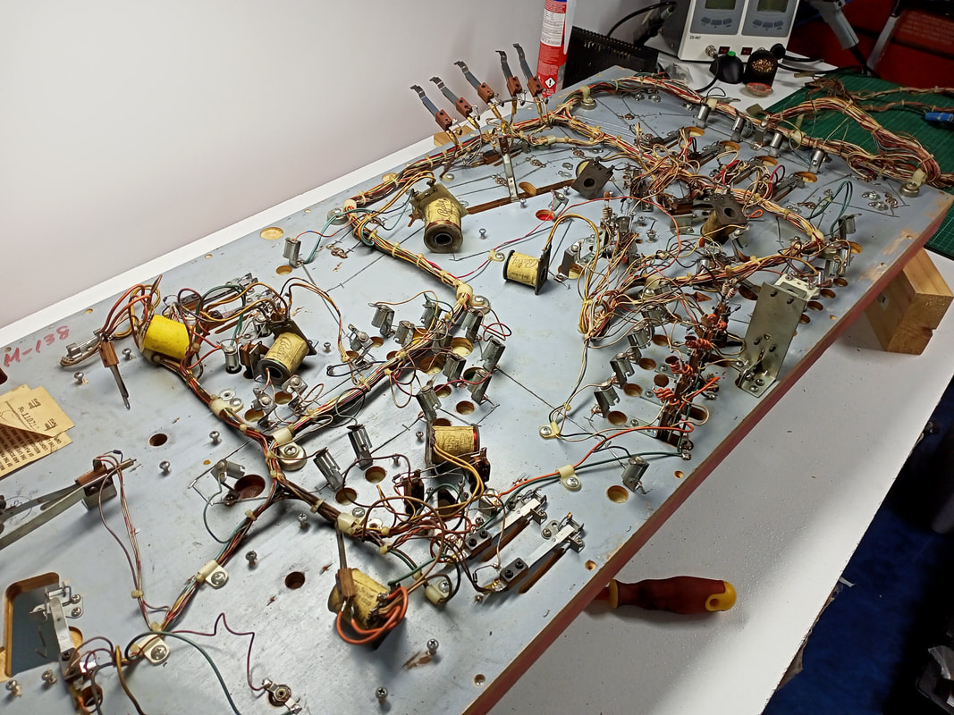
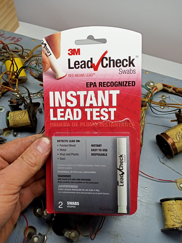
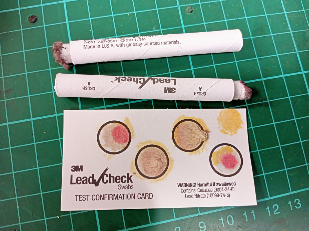
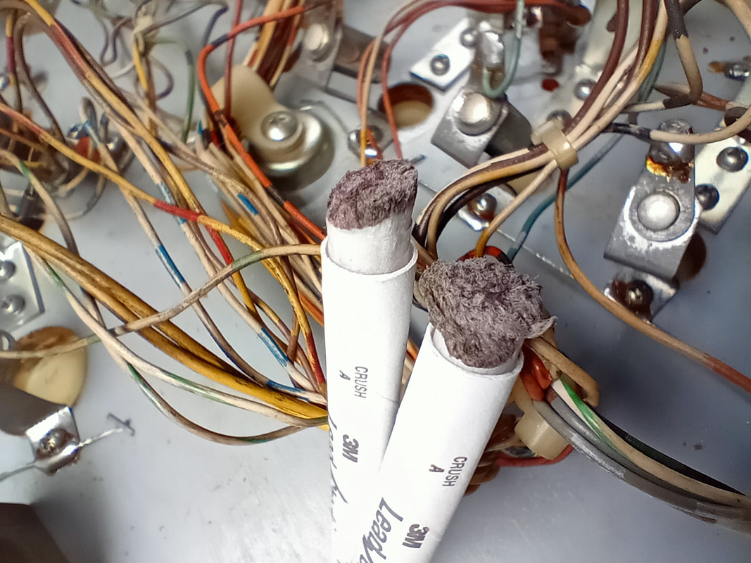
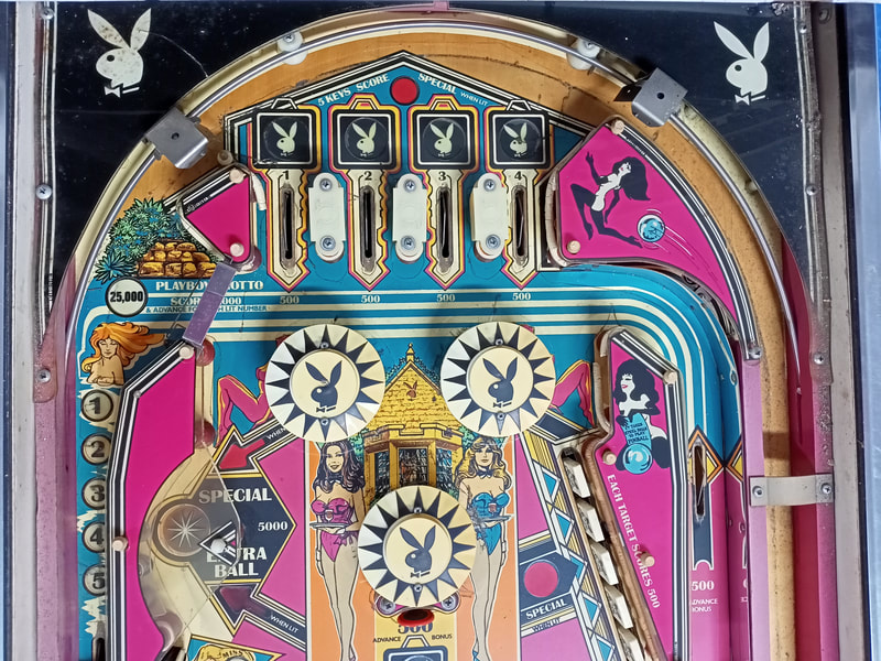
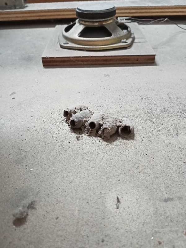
The biggest surprise with this game was that, even though the timber was falling apart and there was a wasp nest inside the cabinet, it actually booted up and played! I was pleasantly surprised. Obviously, the game played poorly, and all of the playfield mechanisms were either gummed up or otherwise working sluggishly, but the main point was that things did work. Once I identified a couple of basic issues with dodgy lamps and switches not working, I got straight into the tear down and repair. It's good when a game is working from the get-go, as you can tear the game down knowing that it should work properly when put back together! Disassembly Playboy has a simple playfield with only three pop bumpers, a five-bank drop target assembly, a kicker, and two slingshots. As well as a few standup targets, that's all there is to it. No special precautions needed for disassembly. I found that it made things easier to take off the drop target assembly from underneath the playfield, as it is the largest mechanism attached to the underside. With the drop targets gone, you can more easily place the playfield down on a bench. I found this approach worked best for working on the playfield while it was out of the game. Remember to take photos if you're unsure of where plastics or other playfield parts go, particularly if you're disconnecting the playfield to remove it from the cabinet. Bally playfields are quite light and can easily be lifted vertically out of the cabinet by one person. A word on safety is warranted here. Pinball machine manufacturers often used lead paint for cabinets. This is primarily a concern when sanding a cabinet back for repair and new artwork, however it's also a concern with extremely damaged side art such as on this game. Paint was flaking everywhere whenever I moved the machine. Respiratory protection should always be worn when there's a chance of inhaling lead dust or lead paint fragments. However, you can also use a presumptive test to check whether or not the paint in question is likely to contain lead or not. 3M sell a presumptive test for lead which comes in the form of "sticks" which can be rubbed on the surface to test for the presence of lead (Bunnings). They're expensive, but worth it if you're going to be doing a lot of cabinet work on older games. Lead paint was banned in the United States in 1978 (the same year this game was made) but only for residential applications. It was still used in commercial applications into the 2000s. So it's a good idea to do a quick check whenever you're working on a game. The test is pretty simple. Crack the glass vial within the test stick to mix the reactants together. Then, rub the stick on a surface to test. I wish I had thoroughly cleaned the surface I was testing first, as the stick will collect dust and dirt which makes it difficult to actually observe any colour reaction. A red colour will indicate the presence of lead (subject to the minimum detection level and other factors which are explained on the documentation supplied with the test). There is also a confirmation card which functions as a positive control to ensure the test is working properly. Red dots on the test card indicate a positive reaction as seen in the first and fourth dots. The test sticks are shown below. Both are actually negative tests - no red colour was observed. However you may note a slightly red hue to the top test stick. This was because I rubbed a couple of bits of solder on it to check whether some of my solder was leaded or not. You can see a very, very slight red colour on that top stick as a result. However this was from the solder, and not the cabinet paint. So, good news! No lead in the cabinet paint, so we are good to go. For those interested, there are some interesting posts on Pinside where people have tested other pinball parts for the presence of lead:
And now, on with the disassembly show... After disassembly, the game went through my standard restoration process to get it playing and looking like new. During the restoration process, I dealt with a number of issues, described below. Tips & Troubleshooting (click on sections below to view details) Lamp issues
Given that this is a Bally game, you can expect a lot of lamp issues! Bally lamp sockets are notoriously crappy quality, and after 40 years, there are always a number of them which are starting to fail. Moreover, issues with the lamp driver board or wiring can contribute to lamp issues. This game had both types of issues to deal with - fun!
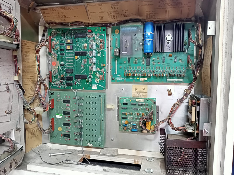
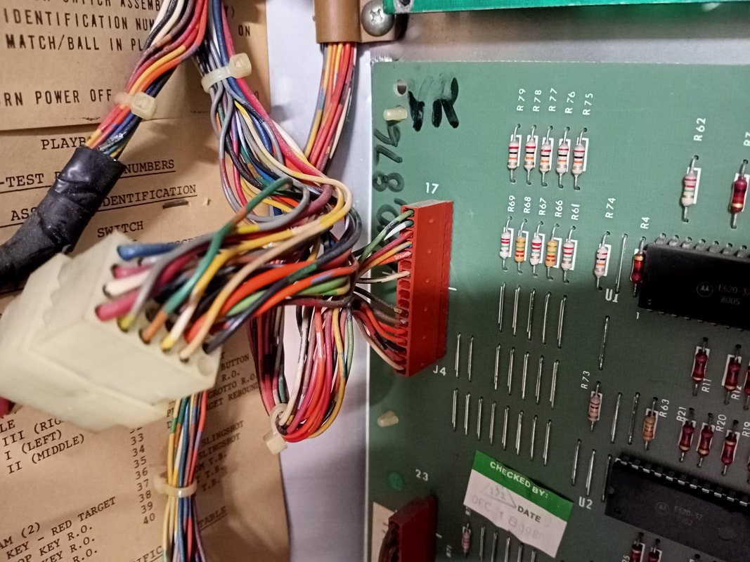
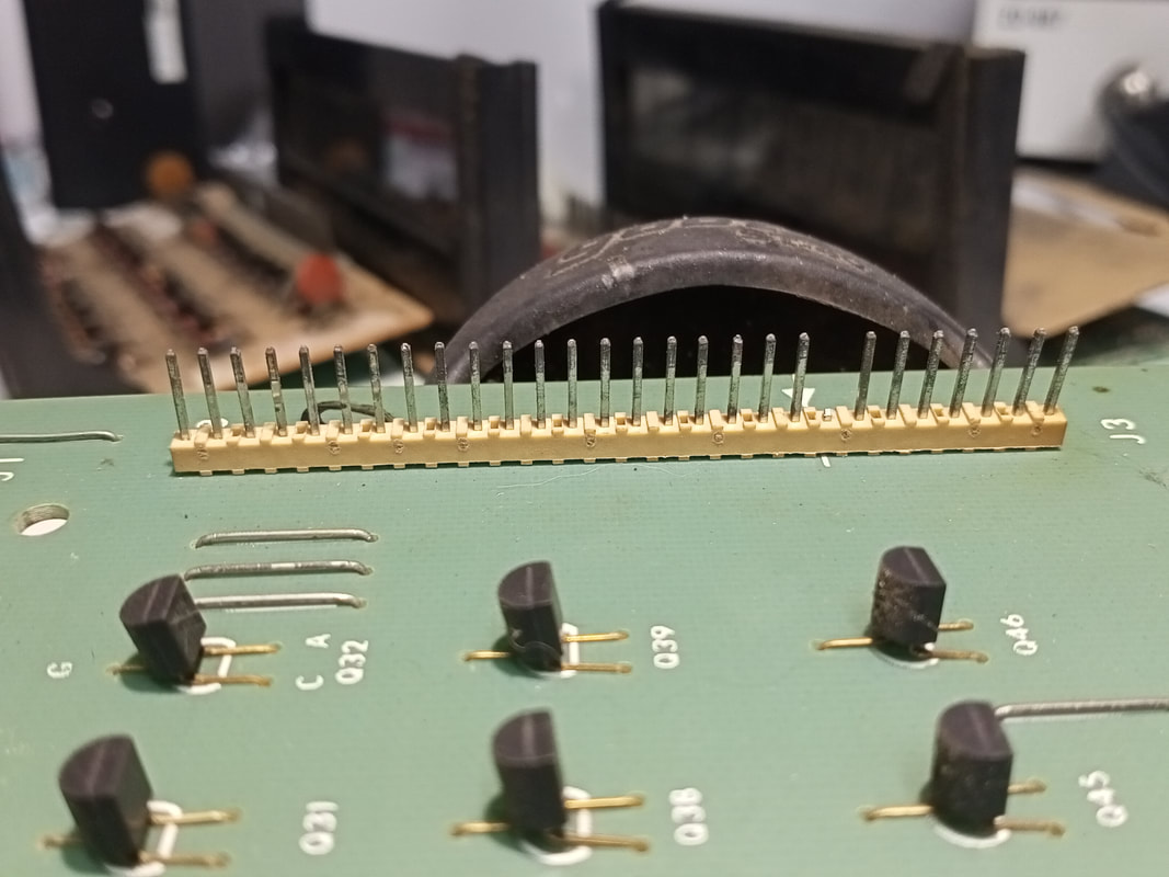
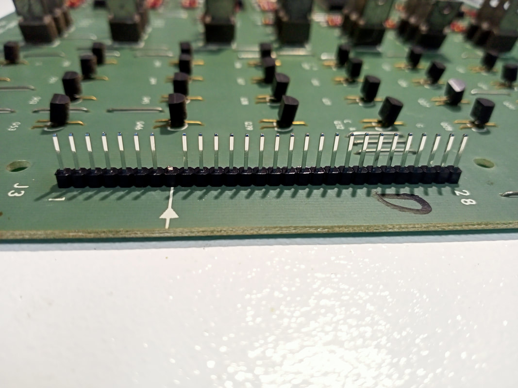
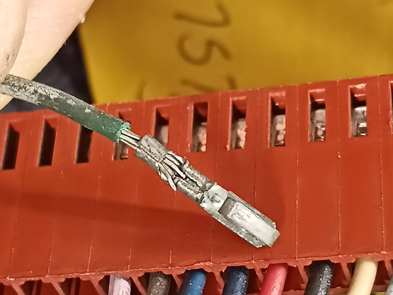
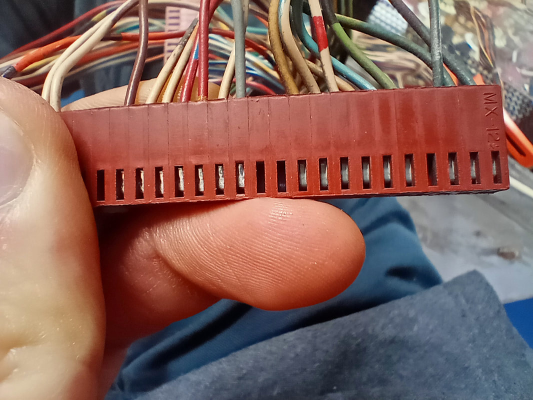
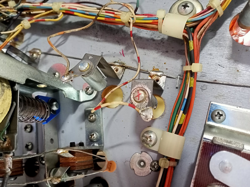
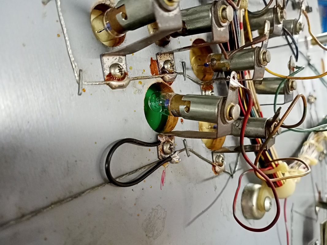
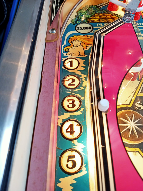
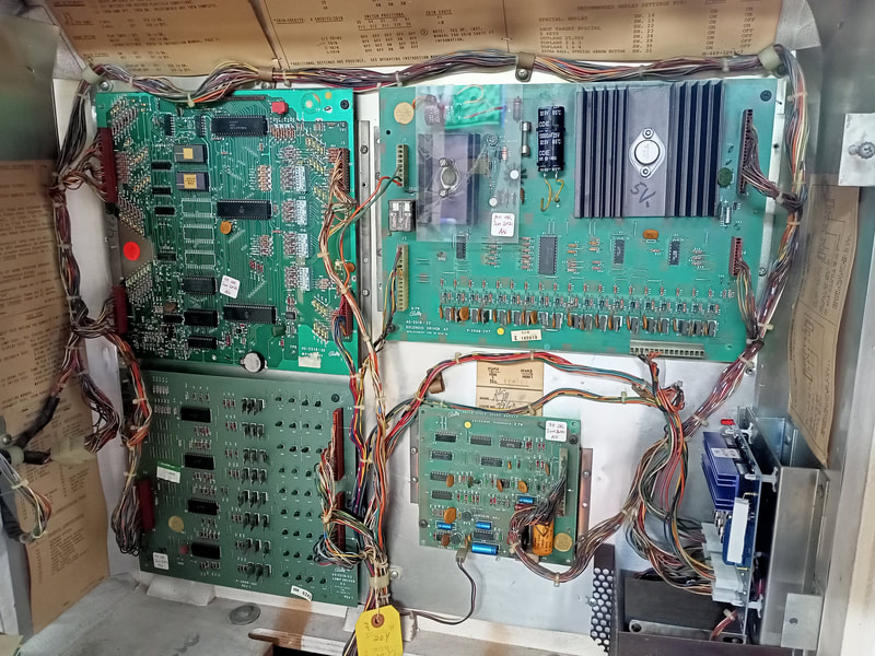
A peculiar issue with the insert lamps on this game was that they seemed to work perfectly (during attract mode) when the backbox door was fully open. However, as soon as the backbox door was shut, they stopped behaving. Instead of lighting up the bonus numbers 1, 2, 3, 4, etc. in sequence, different lamps on the playfield would light up in sequence such as the special lamp, star rollover switch, extra ball lamp, and a few others. This behaviour was totally bizarre but reproducible. As soon as you opened the backbox door again, the lamps started working properly again. To troubleshoot this I looked simply at the backbox door. What could opening and closing it possibly be doing to change which lamps were lighting up? At first I considered a stray wire or grounding cable was brushing up against the door as it was closing. That wasn't the case. Then I had a close look at what happened with the backbox wiring when the door was closing. There is a loom of wires adjacent the lamp driver board. When the door closes, this loom of wires moves around a bit, and ever so slightly touches lamp board connector J4. I held the connector and wiggled it back and forth a little bit and, lo and behold, the playfield lamps would act up depending on how I was manipulating the connector housing. This was the cause of the issue. Movement of the connector was somehow causing different signals to be sent to light different lamps on the playfield. Clearly, this connector needed new terminal pins, and new header pins needed to be installed at J4. At the same time, I replaced the header pins and terminal pins for connectors J1 and J3. This cleared up a couple of problems with playfield lamps lighting inconsistently, or being too dim. I make sure I redo these connectors on every Bally game as the lamps always seem to improve after new connectors have been installed. My trusty SN-28b crimpers (eBay) are still going strong after several years and work well for redoing these connectors. You'll need 0.100" terminal crimps (RS Components) as well as new 0.100" header pins (RTBB, RS Components). I buy these in strips and cut them down to size. I reuse the plastic connector housings, but you can purchase new ones if desired. You'll need a 17 pin housing for J4, and a 28 pin housing for J1 and J3 (RTBB). It's always interesting to see the state of the crimp pins when they are removed from the connector housing. Without fail, I find a few which have been improperly crimped from the factory. Sometimes these crimps still function, but other times they do not, and may not have ever worked since the game left the factory! In addition to the issues with the lamp driver board, there were also issues with the lamp sockets on the playfield itself. The primary problem was general lamp unreliability. Some lamps were flaky in that they would work fine one game, then stop working the next. Bally lamp sockets are notorious for working poorly, and I can't blame them after 43 years! I have tried some of the simple hacks before, such as removing the wire from the tab at the base of the socket and soldering it to the "nipple" instead. I've also tried soldering the bare conductor routed between the lamps to the base of the bayonet holder. You'll need to lightly sand the areas you wish to solder to, so the solder sticks. Regardless, these solutions don't really help if the problem is a dodgy connection within the socket itself, or if the interior of the socket is dirty or corroded. Best practice in my opinion is to simply replace the problem sockets with new ones and be done with it. Unfortunately, bayonet lamp sockets are expensive. Most suppliers sell a variety of sockets suitable for #44 lamps, with different lug and mounting configurations. Similar styles to original sockets (part no. E-120-127) are available (RTBB, PSPA, Mr Pinball). It doesn't really matter which ones you use, as long as they allow enough space for the lamp to sit under the insert. The main pain point is going to be price. I only had to replace six sockets on this game, but at over $2 each, a playfield full of dodgy sockets can cost a lot and take a lot of time to repair. I find it difficult to solder the lamp sockets back onto the original ground braid. Mainly because there's not much space on the mounting tabs to solder the braid back on, and it's hard to manoeuvre your soldering iron around some of these sockets. So, I prefer to solder a wire to the mounting tab of the socket while it is still on the bench. Then, I simply solder the other end to a spot on the ground braid. This gives you some flexibility as to where you can solder it, so you can pick the easiest spot to work in. There is another option. You can now get small LED circuit boards which can be screwed directly into the playfield using the same screw holes as the original bayonet socket. These are actually a cheaper option than replacing a discrete socket and installing a separate LED, and are available in both cool and warm white colours (dyopp21 on Pinside). Awesome! I will definitely give these a try in a future restoration, but for now, it was easier to keep this machine original. Display panel refurbishment
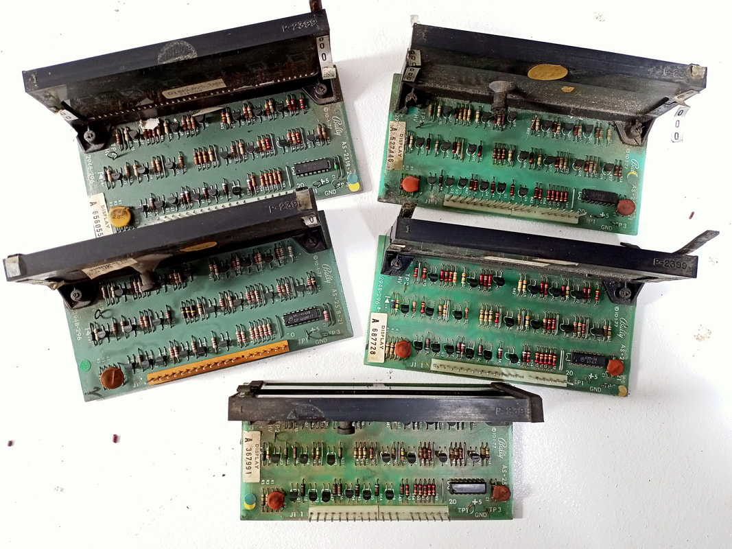
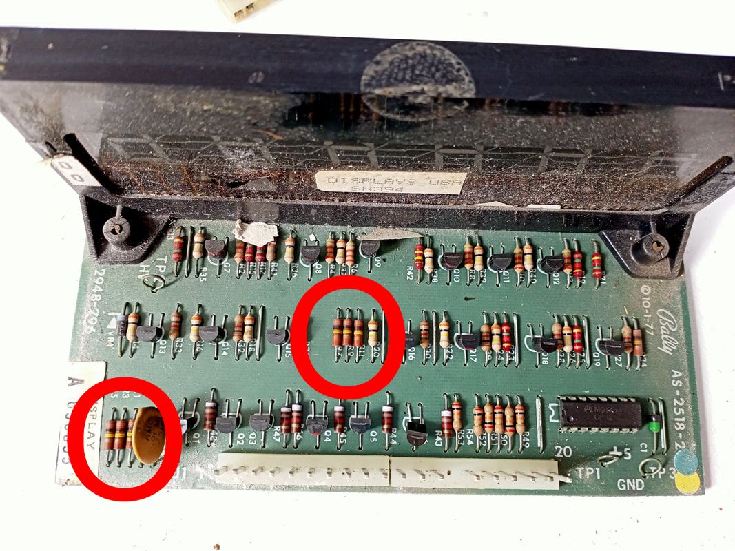
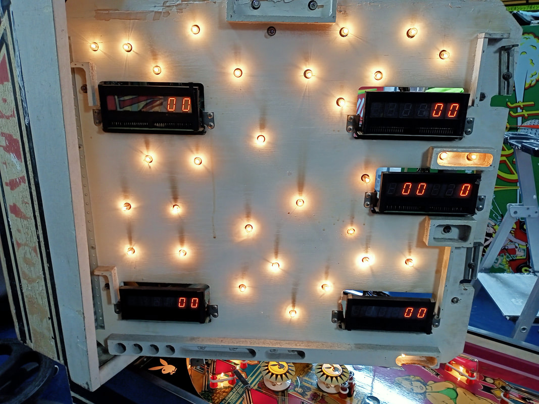
Playboy uses five six-digit displays. While all of the displays appeared to work on this game, they were all in original condition, and therefore needed a couple of upgrades to ensure ongoing reliability. Pinwiki's guide for Bally display repair is a fantastic resource for working on Bally displays, and id adapted from Steve Kulpa's original repair documents. Not exactly bedtime reading, but a good resource if you're going to dig into any display problems.
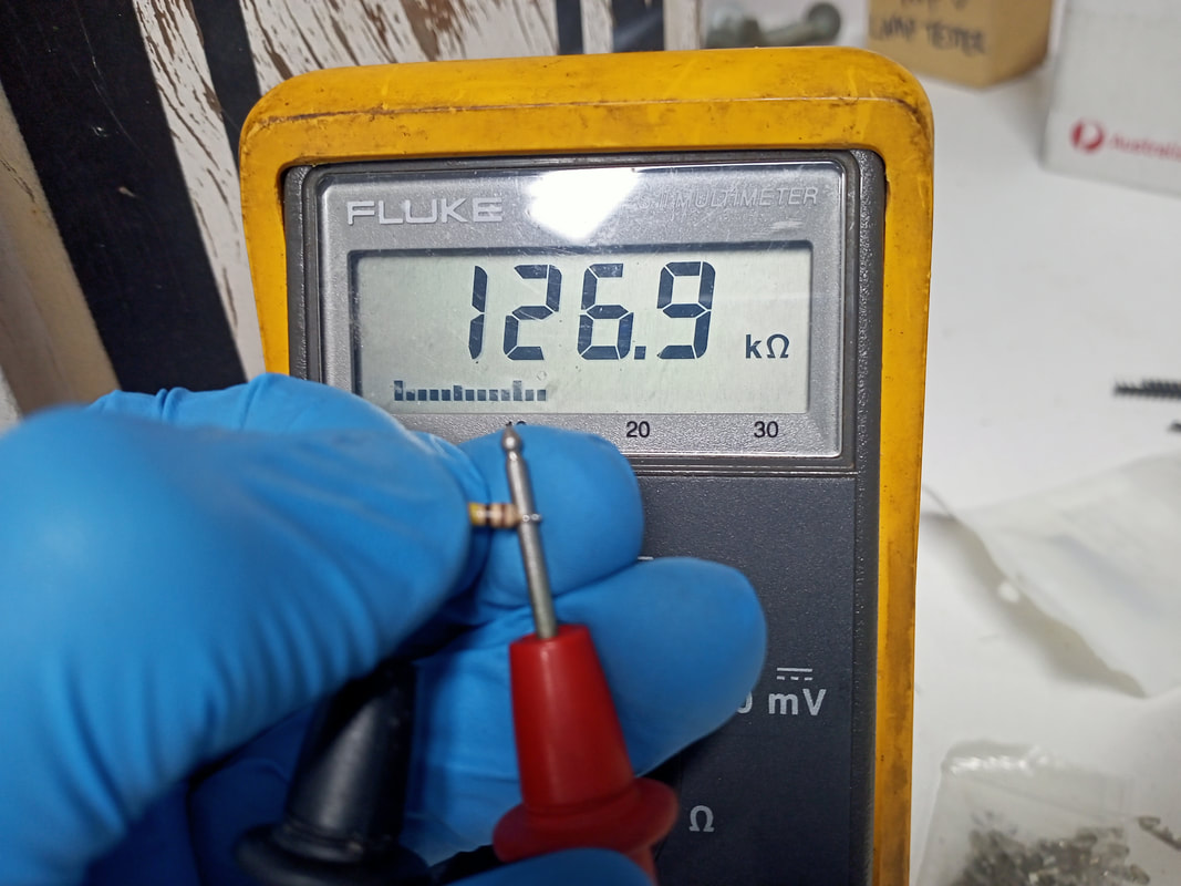
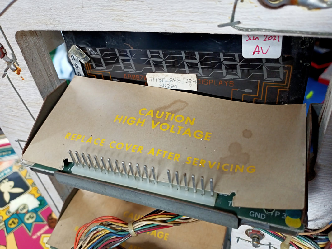
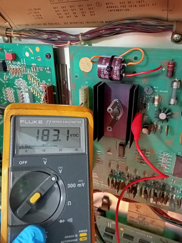
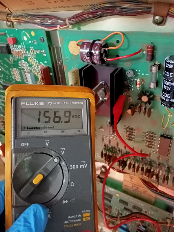
The first upgrade was a thorough check of the display header pins. All seemed to be in relatively good condition, with no cracked solder joints. These header pin solder joints had been reflowed by someone previously, and they appeared to have done a good job, so there was no need to repeat their work. The components on the display boards were all original. This meant that the resistors at R1, R3, R,5 R7, R9 and R11 were all 100k ohm, 1/4 watt resistors, which is severely underrated for this circuit. These were all upgraded to 1/2 watt resistors (Jaycar). As there were no other issues with the display boards, they went back into the game for testing. The cardboard covers for each of the boards were still intact, so they also got a clean before reinstallation. A lot of people don't bother with these covers, but I think they make for a clean installation and they do serve an important purpose - to protect the display circuits from debris and falling screws. These covers are usually missing or torn, but can easily be replaced with some thin card stock from Officeworks or a craft store. With the displays back in the game, it was time to ensure they were operating at the correct voltage. Bally games tend to run the displays a higher voltages than necessary, which reduces the life of the display. To check this, turn the game off and connect your red multimeter probe to TP2 on the solenoid driver board. You'll need to remove the plastic cover which protects this section of the board. Be careful working here, as high voltages are present. Connect the black probe to ground. Turn the game on and take a DC volts reading. Values of 150-160 are good. Anything over that is too high. These displays were measuring at over 180 volts, which was too high and needed to be reduced. The potentiometer at RT1 (labelled "HV ADJUST") on the solenoid driver board can be turned counter-clockwise to reduce the supply voltage. Turn it down as far as it will go, while still providing the displays with enough power to light. If the displays go blank, turn it up again. I turned this potentiometer to its minimum, which sent a voltage of 156v to the displays. With this voltage, the displays were still nice and crisp. Perfectly adjusted. Rectifier board replacement
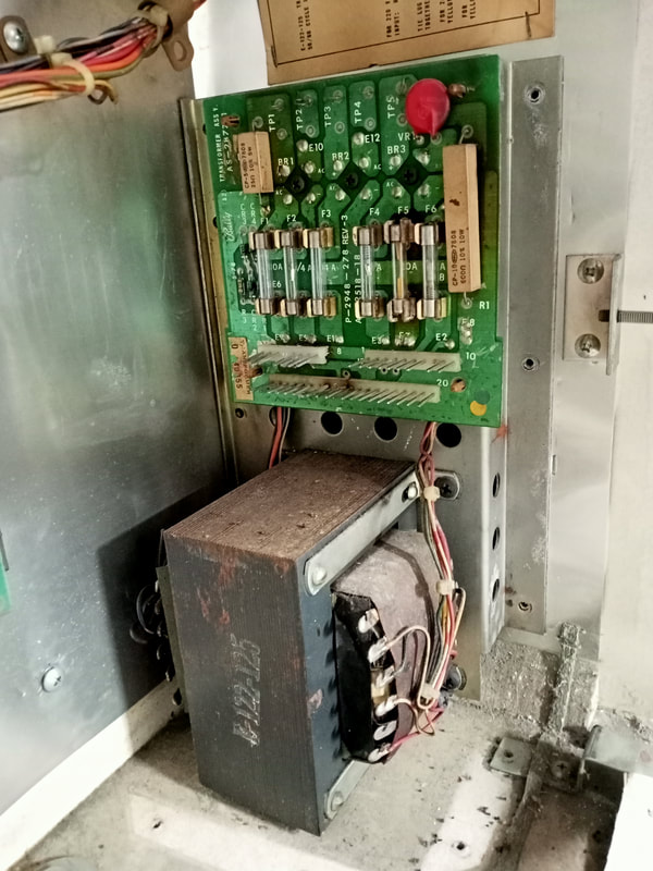
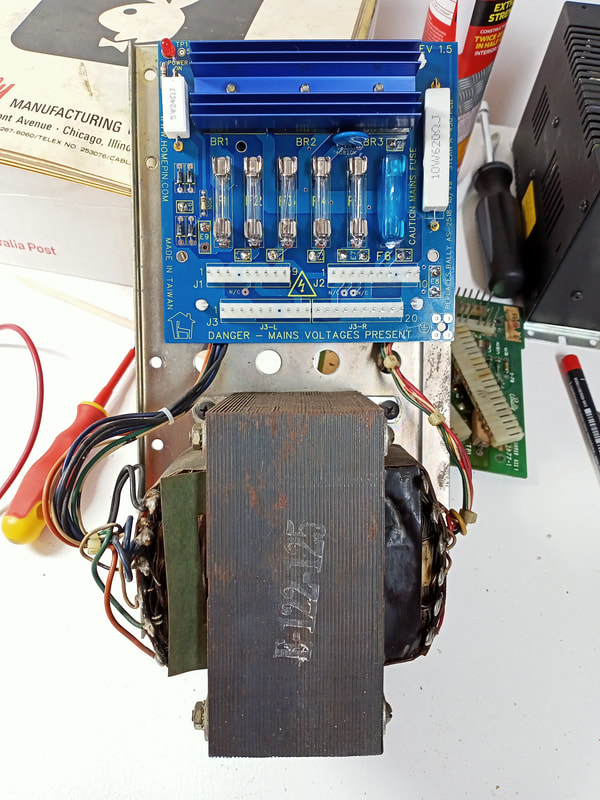
The rectifier board and power transformer in Bally games is located in the bottom right corner of the backbox. This bastard is the reason that Bally backboxes are so heavy compared to Sterns (Stern put their transformers inside the main cabinet). Since this board is the first board after the transformer, it is responsible for rectifying all AC voltages from the transformer, fusing them, and distributing them to the other boards and playfield components. Pinwiki has a great gallery of pictures with the various revisions of rectifier boards.
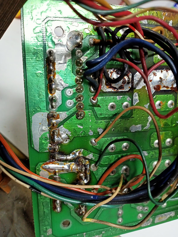
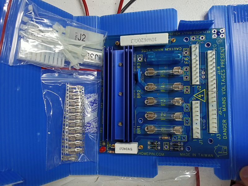
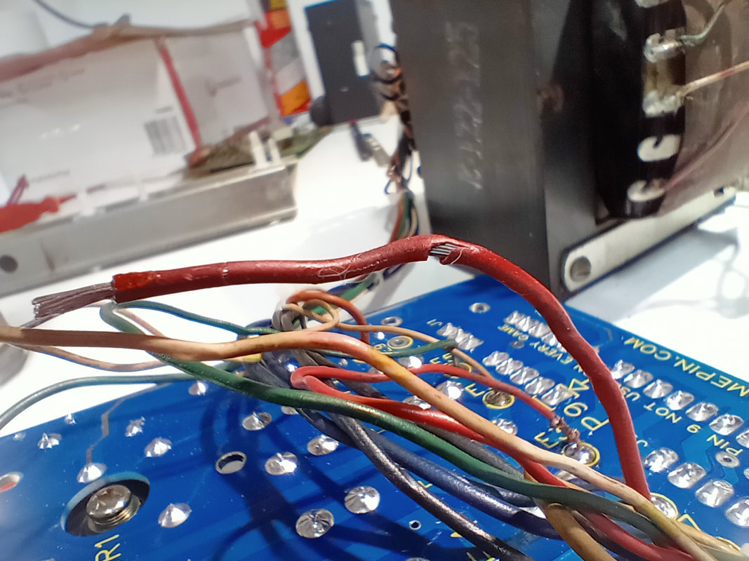
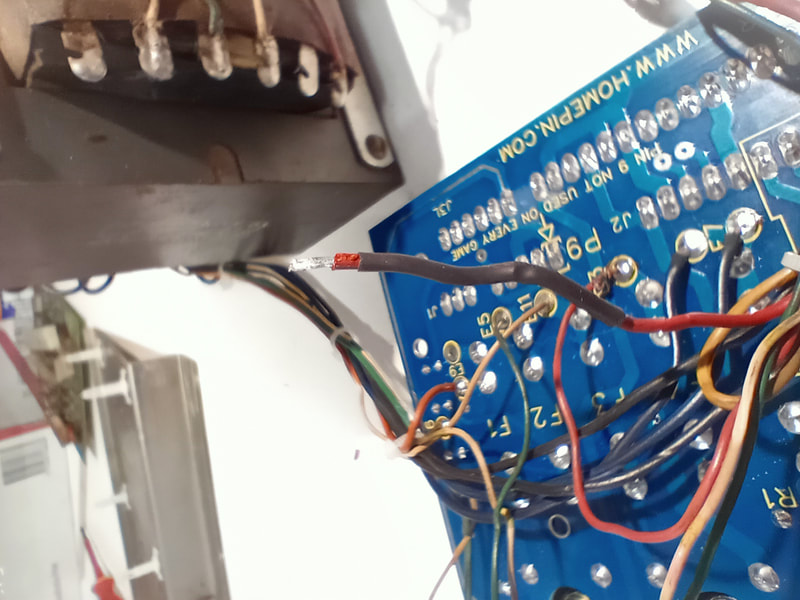
There are a lot of issues that stem from the rectifier board. Unusually, the fuses and voltages all checked out OK when I first powered on the game. I always expect at least one of these to be out of whack, so this was a pleasant surprise. Be sure to do this with only J2 (input) connected, and J1 and J3 disconnected (playfield and backbox outputs, respectively). Once you confirm voltages are OK, you can plug in the output connectors with the knowledge you're only sending the correct voltages to your circuit boards and coils. Even though the voltages were OK, this board starting giving me problems within a couple of days of starting repairs. Eventually, the game refused to power on, and I was no longer seeing the expected voltages at the test points at the top of the rectifier board. On top of this, the board itself was misshapen (bent from heat damage), header pins and connectors were burned, and it looked like shit in general! There are two options here - refurbish the board, or replace it. Refurbishing is a simple process but involves a lot of fiddling as you need to install larger, more robust components on the board than it was designed for. These upgrades are described in detail on Pinwiki and in Clay's repair guides. The necessary upgrades are numerous, which is all fine and dandy when you have time to muck about. However, after doing a few of these board upgrades, I find it much more time and cost efficient to simply replace the entire board with a new one. For this repair, I decided to try out the Homepin Bally/Stern rectifier board, which had only been released a year or so ago. It is available from a couple of local vendors (PSPA, Pinball Haus). The boards come in a kit containing all components necessary to install the board, including board standoffs and zip ties for cable management - nice! Just bring your own soldering iron! The board looks great with clearly silkscreened component and connector designations. Soldering the board to the transformer outputs is a relatively simple affair. The solder pads are nice and thick which means you can apply a little more solder to get a nice, solid connection. Just remember to insert the correct wires into the correct through holes! A handy chart on Pinwiki is available for reference in case you forget what goes where. The only downside to this kit is that two 10-pin connector housings are provided to replace the original 20-pin J3 connector. Keying plugs and labels on the connectors specify exactly which half of J3 they are to be plugged into, but a full 20-pin connector is a little safer in that it cannot possibly be plugged in the wrong way. So, exercise a little caution with plugging in these connectors. The terminal crimp pins supplied are also not Trifurcon style crimps. Trifurcon crimps are recommended for high-current connections such as for the general illumination lamps on J1. I recommend purchasing Trifurcon crimps for J1 (RS Components), and using the supplied crimps for the rest. One more detail to note about these Homepin boards. Board revisions prior to 1.8 (made from September 2021) use fuse holders designed to accept 6x30mm fuses. This is not the same as a standard 3AG fuse used in most pinball machines, which is 6.3x32mm in size. The Homepin board is definitely an improvement over the original. The solder side of the original board was a mess, with flux everywhere. The fuse clips were not well tensioned, with some holding the fuse very lightly. This likely contributed to my loss of voltages in the first place. The bridge rectifiers are also hugely underrated, so it's nice to see beefier rectifiers with heatsinks on the Homepin board. The only issue I encountered with installing the new board was that some of the insulation on the original wires was quite brittle. This caused it to break off in some places. However, nothing a bit of heat shrink tubing can't fix. Either way, be careful about bending these old wires too much. Overall, I'd highly recommend the Homepin rectifier board if your original board is having issues. Homepin also sells it in a kit with the entire transformer assembly (PSPA) if you're missing the transformer altogether. It's fantastic that parts like this are being reproduced. Cabinet base repair
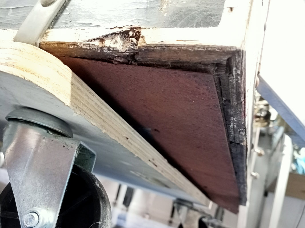
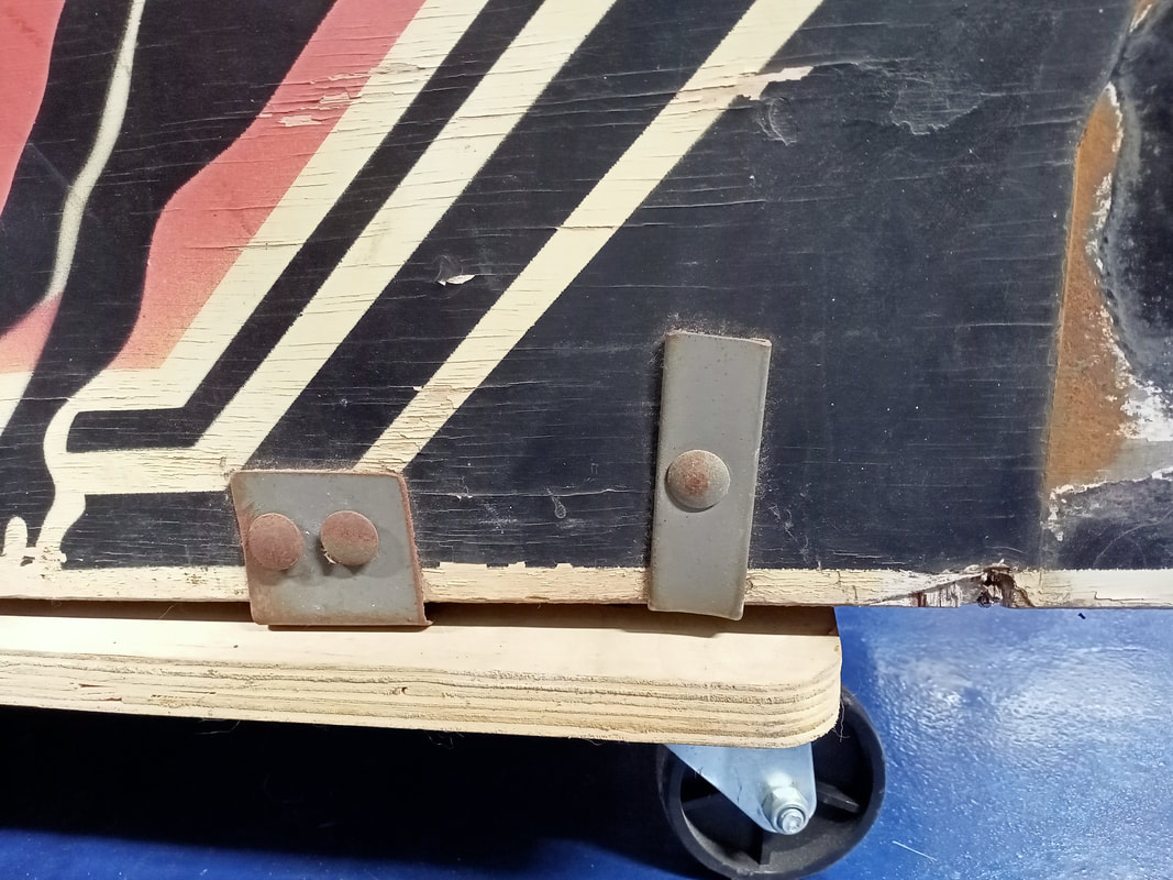
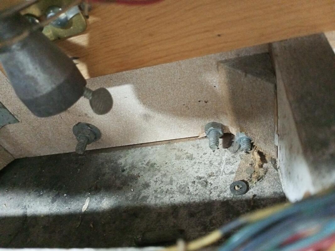
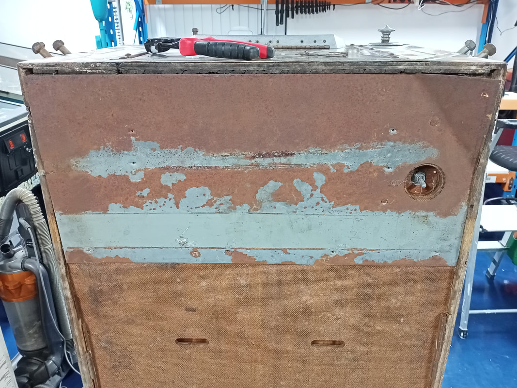
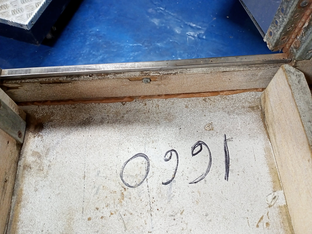
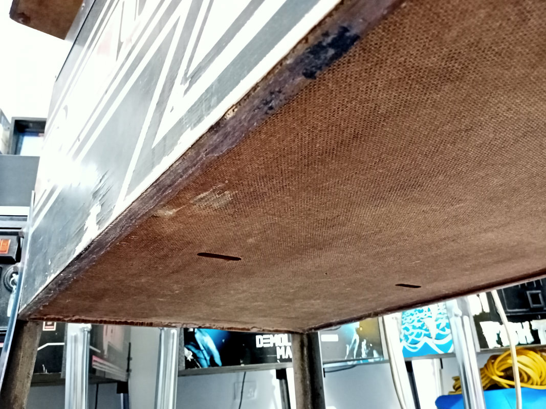
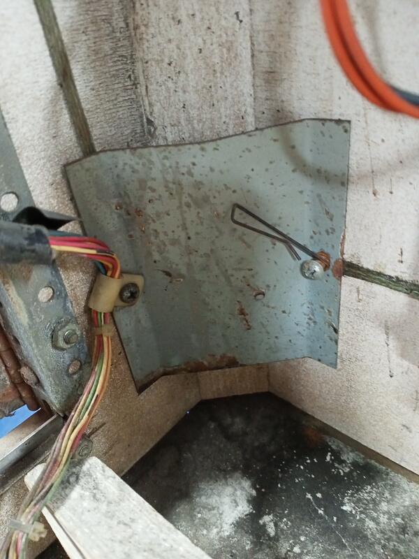
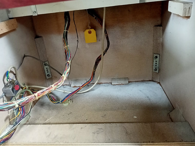
The cabinet on this game was in poor shape, and the cabinet base/floor was the worst. The base board was no longer attached to the sides of the cabinet at the front, left side, and rear. It was only held in place by the intact glue on the right side, and a piece of metal at the front of the cabinet. Bally cabinets of this area have a thin sheet of metal at the front of the cabinet, installed under the location of the coin box. The purpose of this plate is to make it more difficult for vandals to break into the coin box. This plate had rusted and was bent at the corners, which made it a massive laceration hazard. I cut myself on it when getting the game out of the ute and into the garage. I decided to remove it altogether. The problem was that an additional metal bracket had been installed over the metal plate and bolted to either side of the cabinet. Removing these bolts was a pain in the ass, because the nuts which secured them to the cabinet had been massively overtightened into the cabinet timber inside. It took ages fiddling with spanners and pliers to get a good enough grip on the nuts so the bolts could be loosened. I also resorted to cutting slots into the bolt heads so I could unscrew them with a flathead screwdriver.
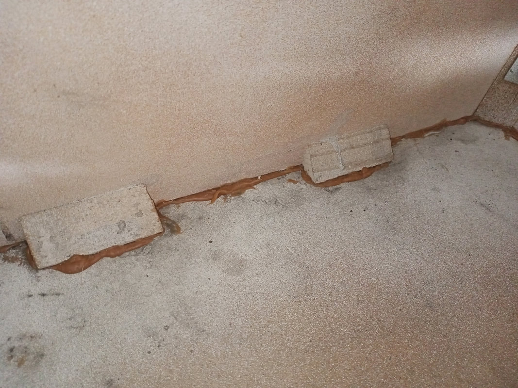
Once the bolts were out and the metal brackets were removed, the nails which were holding the metal plate onto the underside of the cabinet needed to be removed. This is best done with a claw hammer, pliers, or similar tool. Note that the original nails used to secure the plate have slotted heads instead of round heads, so it can be hard to get a good grip on them. Once the plate was out, I could get a better idea of the damage to the cabinet base. Most of the timber had dried up and rotted away, and after a vacuum of the cabinet, I removed a lot of loose timber pieces. The question was whether I could repair this cabinet base, or I needed to make a new one. I decided the cabinet was salvageable, and that I could repair it by simply gluing the cabinet base back in. As the cabinet base was already partly loose, it was a simple matter of squirting some wood glue between the base and the sides of the cabinet, then leaving the cabinet to sit on some chocks of wood to really clamp the glued corners together. I used Selleys Liquid Nails Extreme Strength for this (Bunnings). Here's a tip: this stuff stinks and will give you a headache if you breathe it in for too long, so make this the last thing you do for the day and let the glue odour dissipate overnight. I glued the entire perimeter of the cabinet base, just to be sure the whole thing was solid. I went overboard on this one because with so much of the cabinet impacted, there was no sense in holding back. To clamp the glue in place, I lowered the cabinet onto four bricks, making sure the bricks sat underneath the recessed corners of the cabinet (and not underneath the cabinet sides). This put the full weight of the cabinet and backbox onto the join, which clamped the base piece nicely. No need for extra straps or screws. While this repair was kind of messy, the cabinet was solid as a rock afterwards. This base won't be falling out again anytime soon.! Power cord replacement
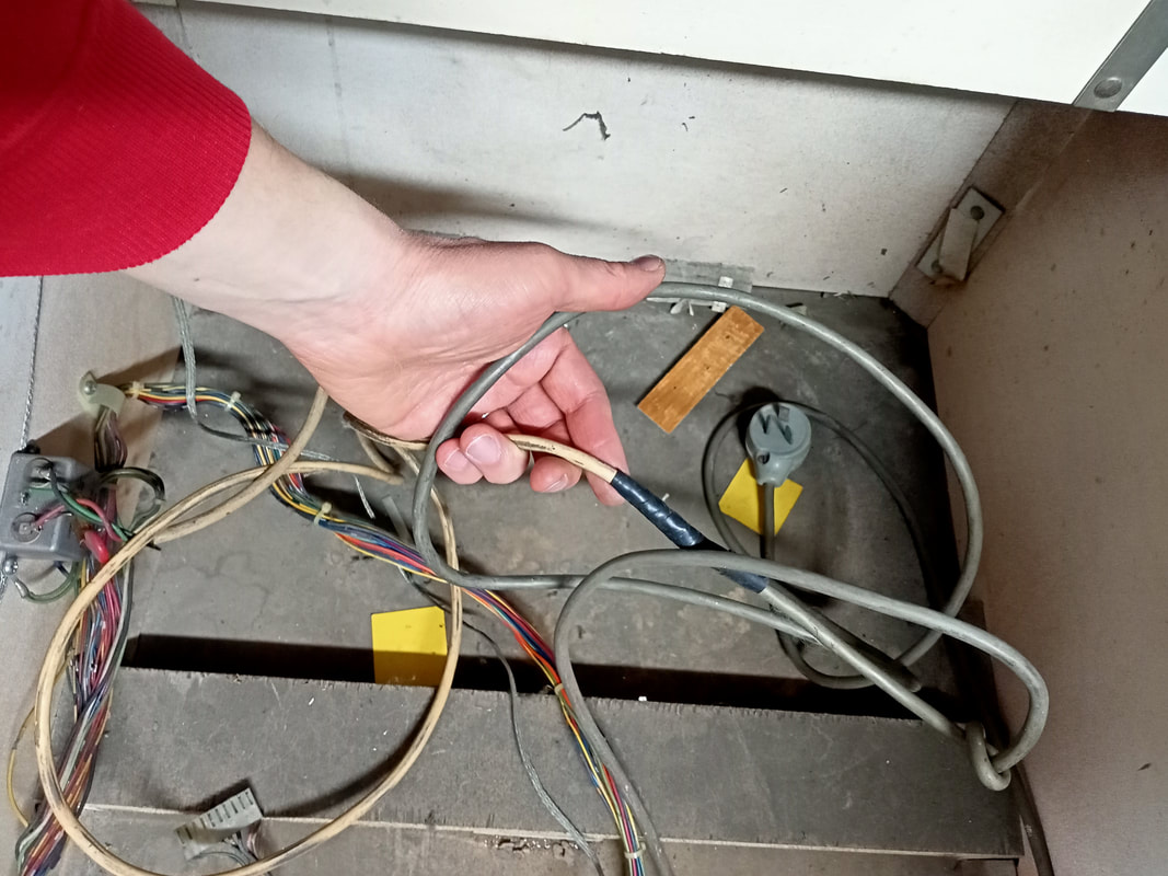
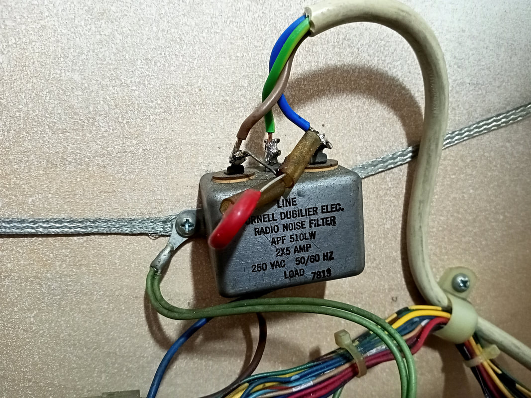
The power cord connected on this game consisted of two separate lengths of cabling, which were connected to each other under a length of electrical tape. There was good continuity between each pin of the plug and the tabs of the line filter in the cabinet, but I never like seeing electrical tape on a line cord. So, this cord was replaced in its entirety.
Leg bracket and leg repair
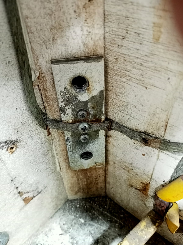
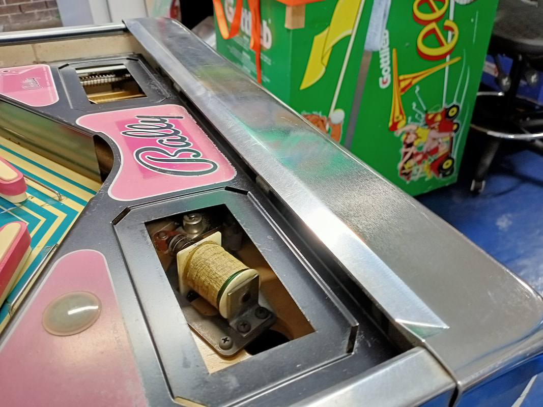
If you've ever packed up a Bally game for shipping, you have probably noticed that some of the legs are quite loose, even if the leg bolts are only very slightly undone. This is because the leg bolt mounting bracket on the inside of the cabinet is usually loose. These brackets were originally nailed into the cabinet at the factory, and over time, these nails work their way out of the timber, resulting in a loose bracket. You don't notice this when the legs are tightly bolted on, as the pressure will hold the bracket securely against the interior of the cabinet. However, you want the legs to be as stable as possible, so it's best to ensure the brackets are secure.
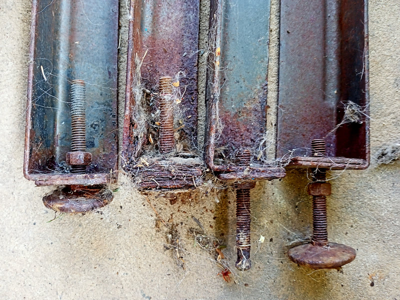
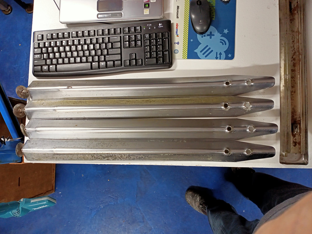
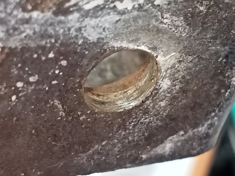
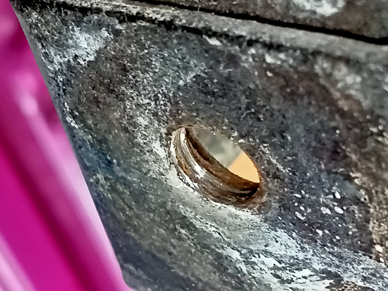
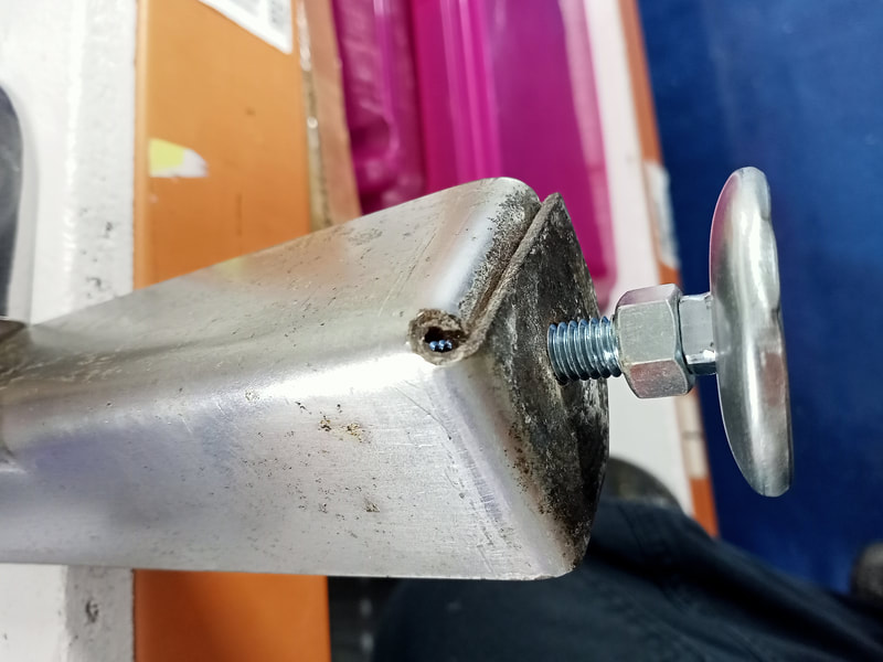
All of the mounting brackets on this game were loose, so I removed them all and replaced them with wood screws. Screws won't generally loosen as much as nails. If the metal brackets are damaged, they can be upgraded with newer brackets that have more thread for the leg bolt to bite into (RTBB, PSPA, Mr Pinball). However, there is an even better solution. You can install WMS-style leg brackets as used on 90s games (RTBB, PSPA, Mr Pinball). These brackets are much stronger, and mount to two sides of the cabinet, which anchors them in place more tightly. Definitely a worthwhile upgrade. If using these larger brackets, new screw holes will need to be made in the cabinet, and some cabinet hardware may need to be relocated if it interferes with the positioning of the bracket. With all leg brackets, insert the leg bolts into the bracket before screwing it into the cabinet. You don't want to find out that the bolt holes are misaligned after you've already screwed it into place! The next thing to look at was the legs themselves. The legs on this game were completely destroyed. The game was kept in a semi-protected patio area. This isn't ideal, of course, but the bigger problem was that the family used to clean the patio by hosing it down, including the ground underneath the machine! It goes without saying, but pinball machines and water do not mix! The legs were rusted to hell at the base, and a couple of the leg levellers were no longer present as they had simply rusted away. These needed total replacement. Of course, you can buy brand new legs (part no. P-4052-8, PSPA). However, I was doing my best to keep costs down for this customer, so I started looking for a used set. A month or so later, I saw a post on a Facebook pinball group with one of the members selling a whole bunch of legs. As luck would have it, he was selling some 28-1/2" legs which are the correct size for Playboy. However, these were not originally Bally legs as they were chrome, rather than grey. This was no big deal, as the size was the main parameter to get right, and the customer would definitely be happy with the price at $10 a leg! Chrome legs look much nicer than plain paint in my opinion anyway! Once I got the legs home and gave them a quick clean, I removed the leg levellers. These levellers were pretty shot, so new ones went in (part no. M-163-28, RTBB, PSPA, Mr Pinball, Austral Amusements, Pinball Haus). There was an issue with one of the legs, though. The bolt hole for the leg leveller was totally stripped, and wouldn't take the new leveller. This is quite common as leg leveller threads get gummed up with dust, dirt, grease, and all kinds of other crap after sitting in dingy, dirty arcades and bars for decades. So, the solution to this is to simply clean the threads with a thread chaser (best option), or simply re-thread with a tap. I had a 3/8" tap handy, so I used that. Using a tap carefully won't remove much thread material so you won't significantly weaken or widen the threads. Even if you do damage them a little, simply place a nut on the underside of the leg to support it. I do this for all old legs as a matter of course. Coin door refurbishment
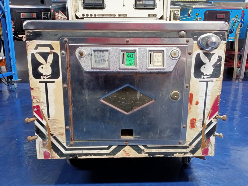
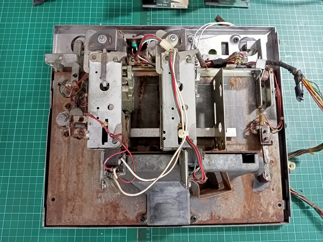
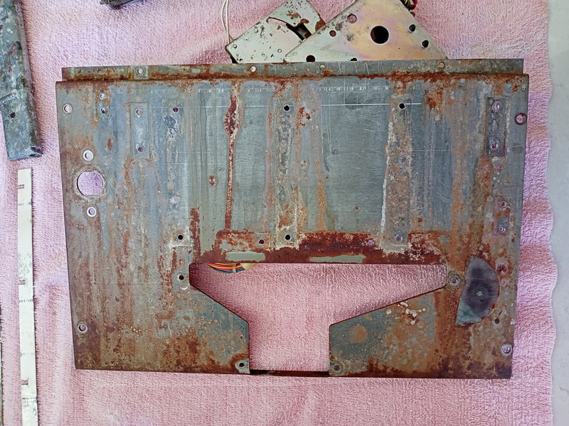
The coin door on most pinball machines is beaten and abused. It's a little worse for older games from the 70s and 80s, as coin doors of this era were often entirely metal with little in the way of protective coatings. Powder coated coin doors of the 90s and onwards are often in much better condition because the pain and topcoat prevents dirt and water ingress. This door was not so lucky. While the front of the door looked quite okay, the rear was another story.
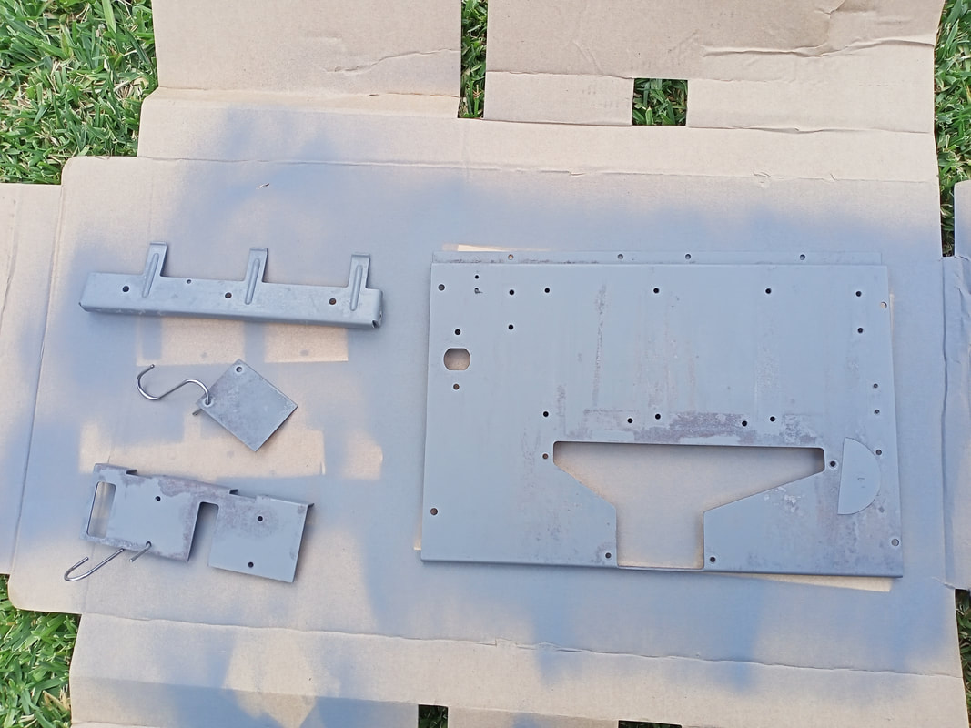
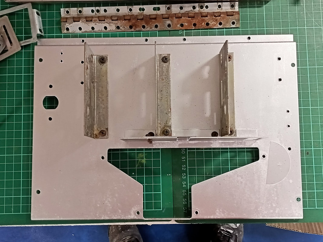
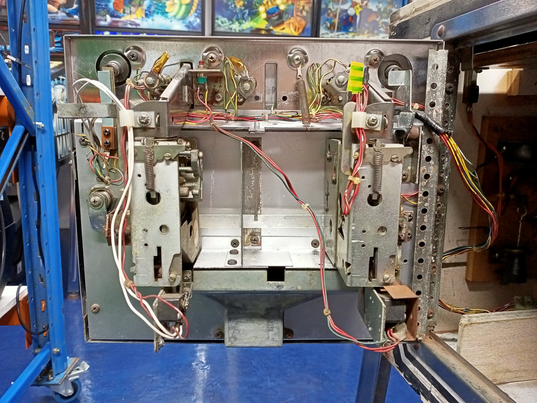
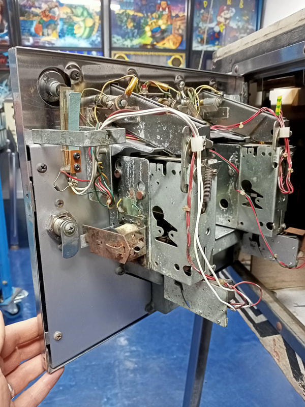
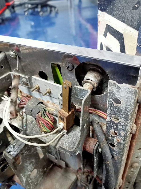
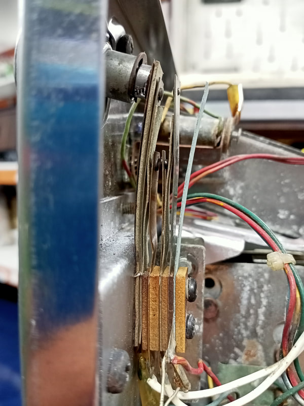
So, this door was going to get torn down, cleaned, and rebuilt. This would not be a full clean and rebuild, as restoring a door properly like this takes many hours. Instead, I focused on the most damaged parts - the backing plate, rejector arm, coin slot cover and coin return cover plate. If you're looking at a coin door and have no idea on how to take it apart, have no fear! There is an excellent guide by Pinside user TractorDoc which covers the entire process of coin door disassembly and reassembly. In fact, I forgot to take a couple of pictures and found exactly what I needed in his guide. Once everything was apart, I cleaned things as best I could, then took the rustiest bits outside for painting. I coated these with a metal priming paint and then followed up with White Knight Super Chrome spray paint (Bunnings). Note that this paint doesn't look anything like chrome, but instead looks like a bright silver. Any colour will work better than the rusty original, so go nuts! After painting the bad bits and cleaning the not-so-bad bits, it was a simple matter of reassembly, using the guide I referenced above. I made a couple of minor adjustments in the process of putting the door back together. You might notice some white wires going from one of the coin switches to the start button on the coin door in the pictures above. This was the first modification - to add free play functionality to the game. Using an original game ROM provides no setting or option for free play, therefore other techniques need to be employed. They are described to good effect on Pinwiki. Setting a low replay score is all well and good, but you'd be surprised how crap some people are at pinball. Before long, you get a call asking how to add credits because they can't break a score of 10,000 (the lowest replay score). Instead, I like to add another switch to the credit button switch stack, allowing you to add a credit and start the game with one button press. Somebody had already tried to install a free play switch by mounting a switch to the rear of the coin reject button, but this did not work. So, I simply moved this switch to the credit button switch stack and adjusted it so that it would activate before the credit/start button. You will need to remove some of the Bakelite spacers from this switch stack, and potentially add some thinner ones. The screws for this switch stack are not that long, so ensure you still have enough length to attach the final stack to the coin door. The next thing I changed was the position of the coin mechanisms. It is typical to have a coin mech on the left and right side, leaving the centre slot empty. However, this game had a coin mech on the right and in the centre. This puts the feng shui of the whole door off! Keep those coin mechs to either side, or install a third coin mech in the centre to balance everything out. While I was at it, I reinstalled the original coin entry insert plastics, which had pieces of paper stuck over them. The old Bally coin entry plastics look really nice, and you can get them in a variety of denominations if you want to change things up (Marco). That pretty much covers it for the rear of the coin door, but what about the front? The front of this door was in relatively good shape, so there wren't any signficant repairs needed. Bally coin doors are quite thin and dent easily, and the entire front panel can be replaced if desired (part no. A-3444, RTBB). This door didn't need any replacement parts except for a coin return flap (often missing on Bally games). This wasn't worth a separate order from the US in this case, but these coin return flaps (part no. P-7493) have been remade by Cliffy (Passion for Pinball). And once all was said and done, we had a fairly original looking coin door (sans Bally decal)! The coin door decal was unfortunately out of stock everywhere locally when I did this restoration. These are available in two varieties, the normal "Bally" style (part no. M-1895, RTBB, Mr Pinball), and a "Susan B. Anthony" variation (part no. M-1895-1, Mr Pinball). There is some cool history behind these decals. Susan B. Anthony was a suffragette in the United States, and a US dollar coin was minted in her likeness at the time Playboy was being manufactured. These dollar coins required new coin mechanisms, and the decal was supposed to signify that the game would take the new style of coin. A topper was even produced to inform players that the game would take the new coins. While it doesn't make a difference in terms of home play, those looking for a time-appropriate look for their games might want to use the Susan B. Anthony decal in place of the plain Bally style. Playfield insert repairs
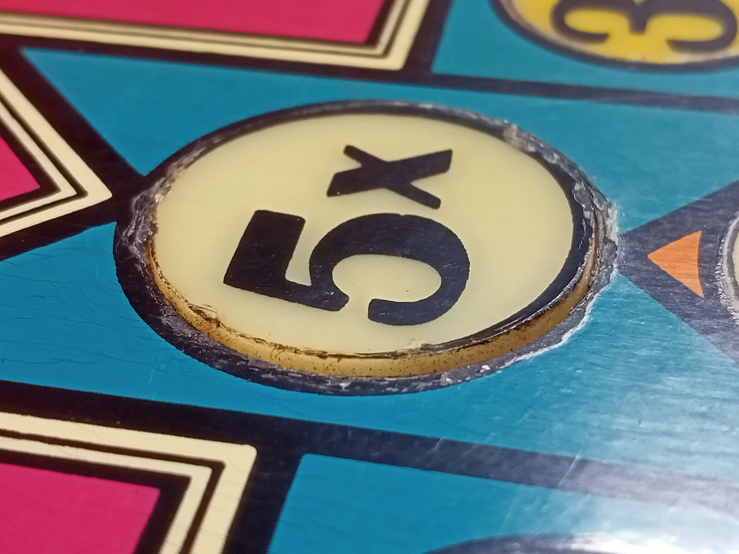
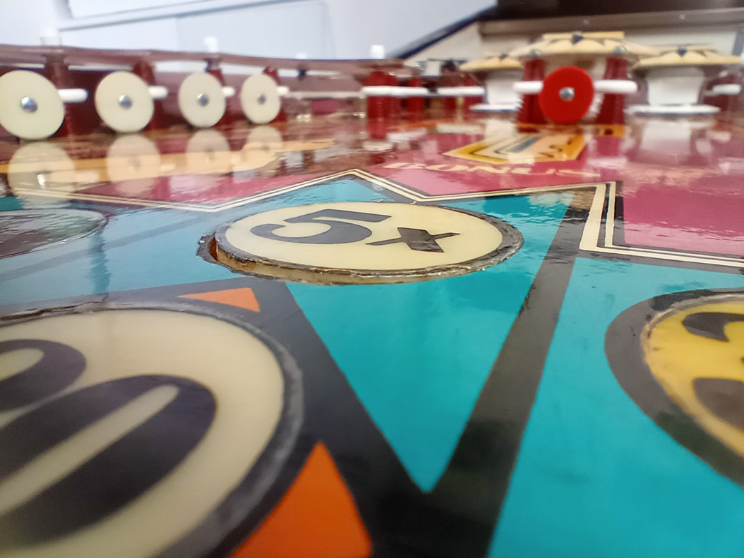
One common playfield characteristic that most 1970s Bally games have is uneven inserts. There's normally a couple of inserts that have either risen up from the playfield, or sunken below it. Normally this isn't much of a problem however when the inserts are in the middle of the playfield and they affect the path of the ball, then it needs to be fixed. Typically, this kind of work is reserved for more extensive playfield restorations however I felt like it was a bit of an insult to leave a raised insert in the middle of the playfield like this, so I set about getting it fixed.
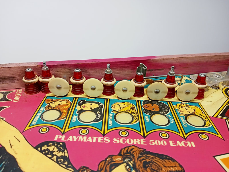
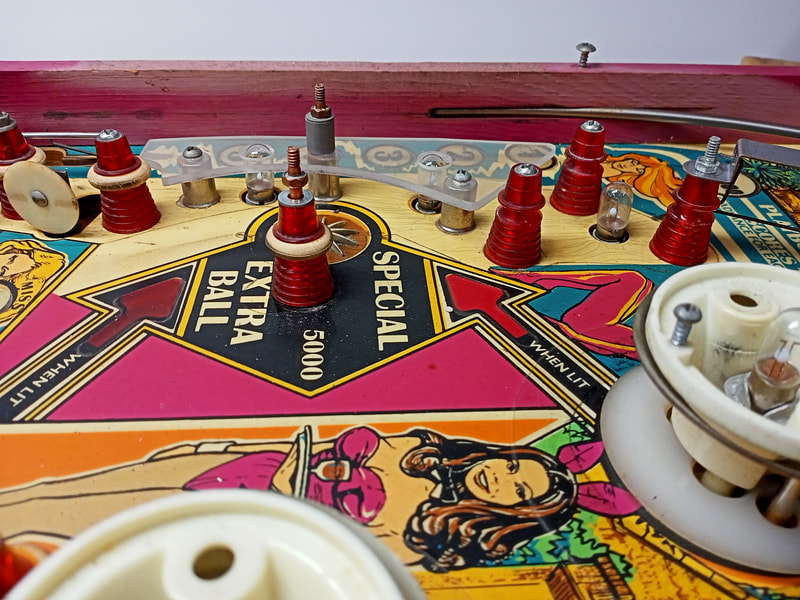
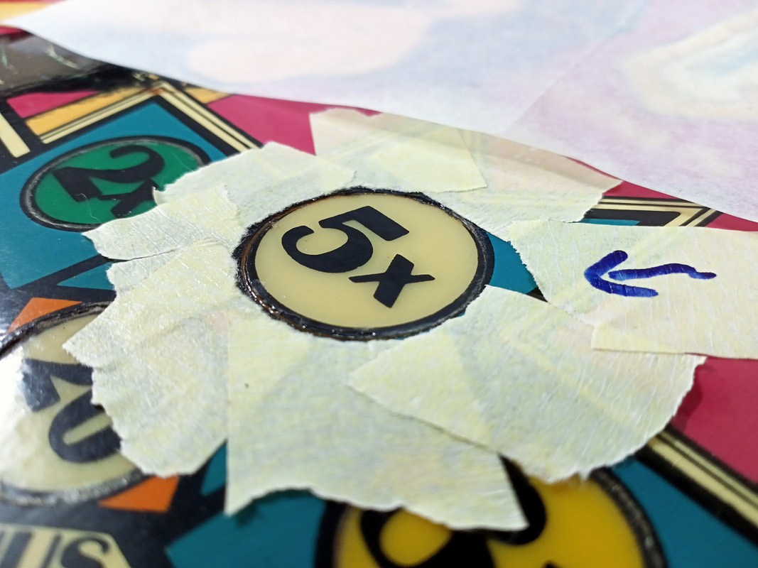
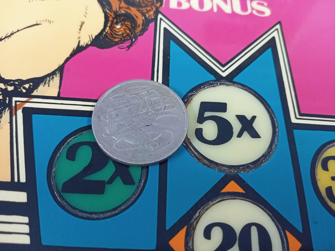
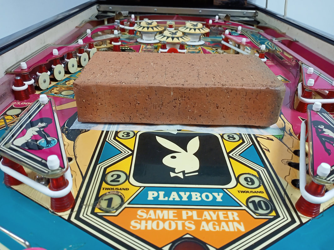
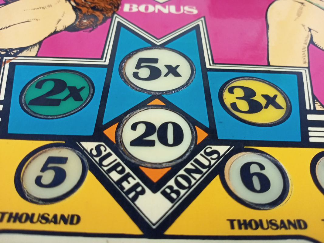
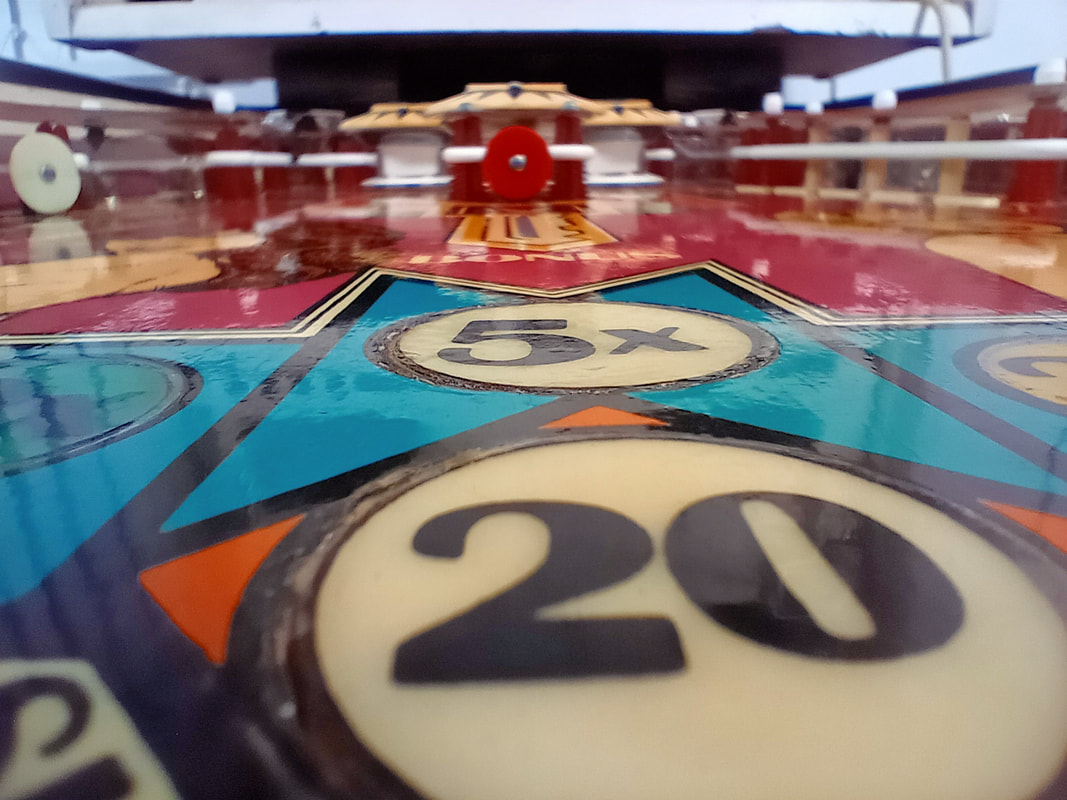
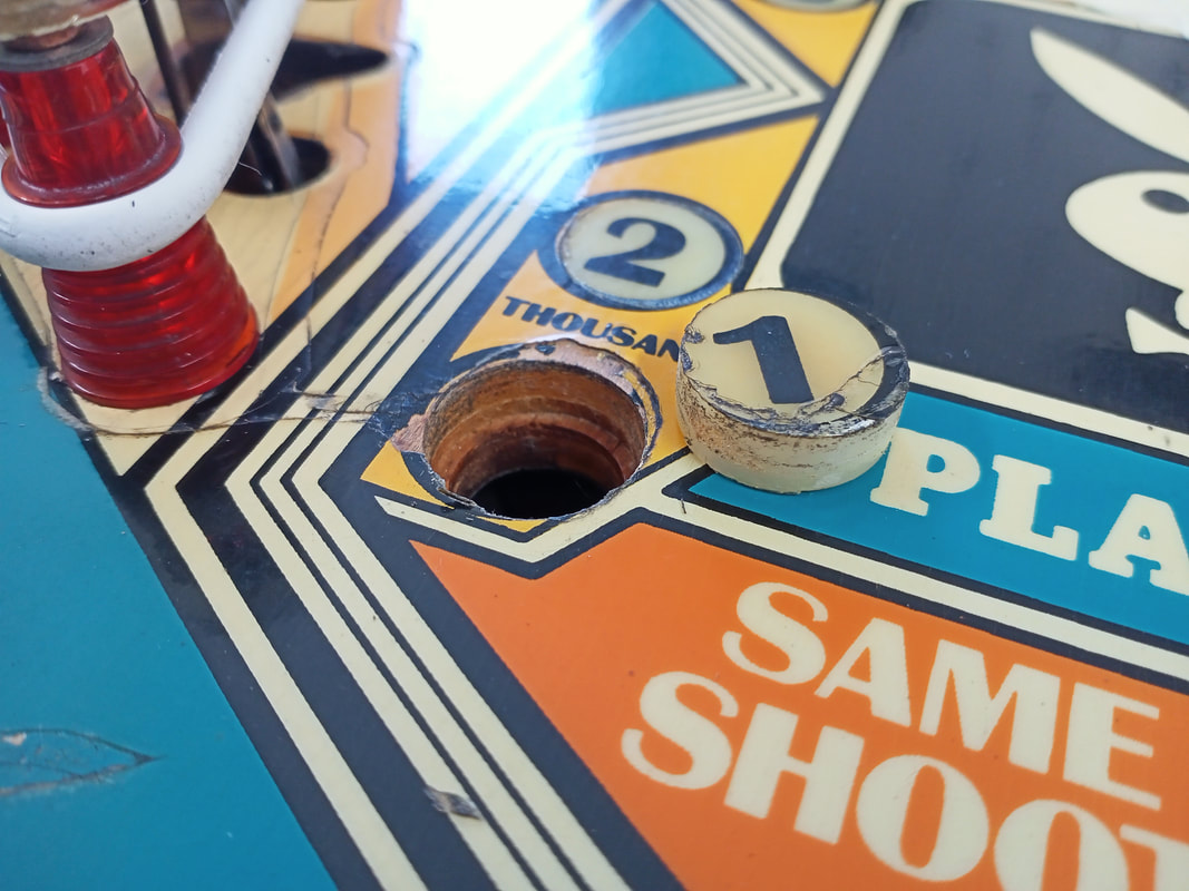
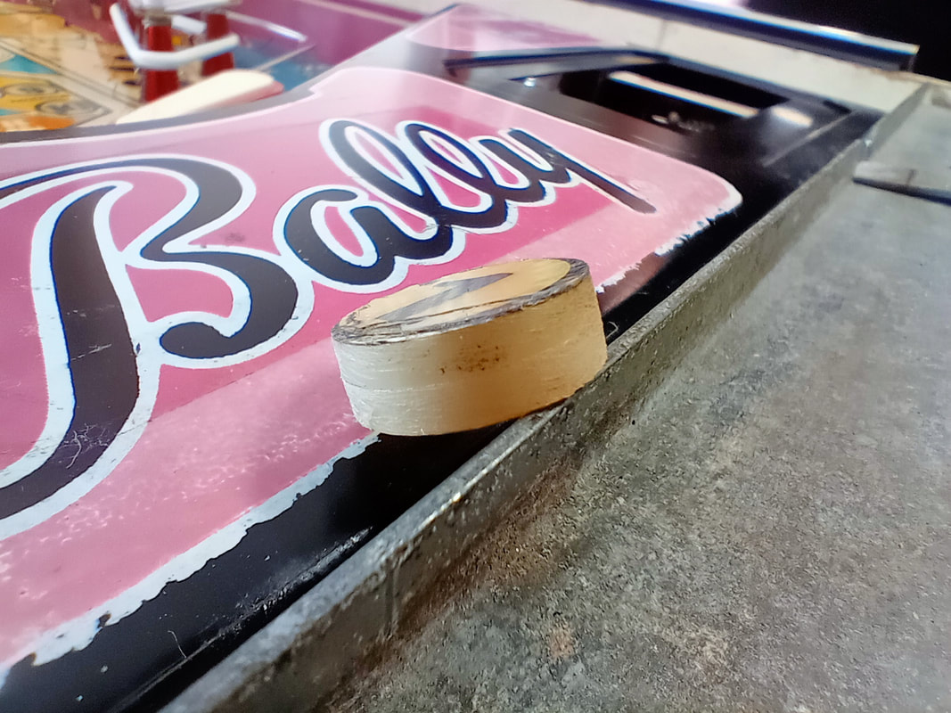
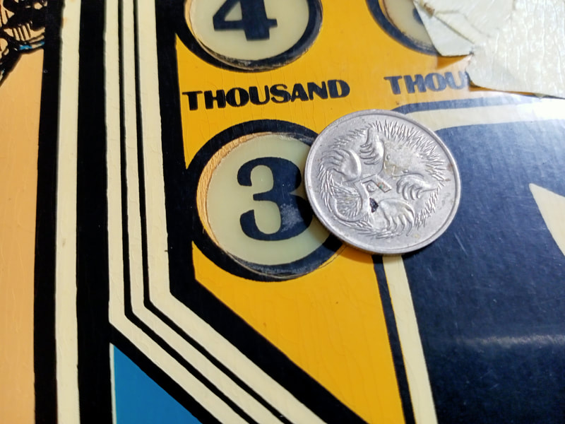
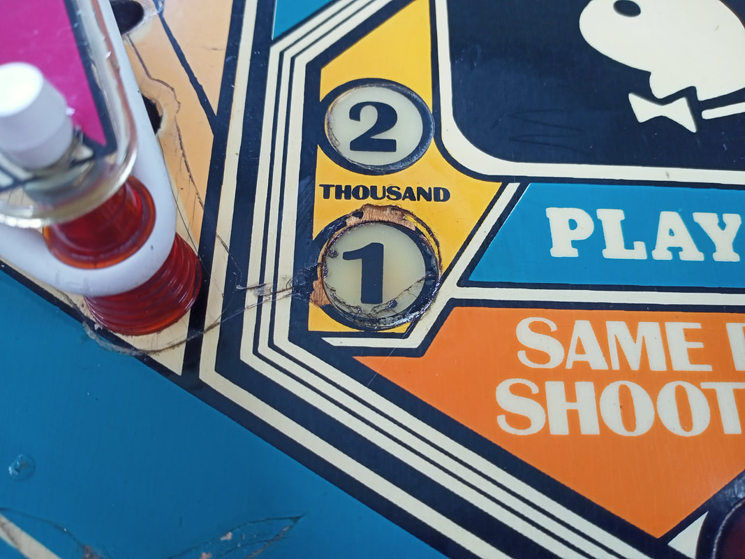
The affected insert was the 5X bonus lamp, and was mainly raised on its left side. The glue in this section had failed and the insert moved freely up and down. The right side remained intact and secure. Now, I prefer to leave inserts in place instead of ripping them completely out of the playfield when one part of the insert is still glued in. Removing the insert fully risks damaging it, either shattering it or introducing hairline cracks. First step in the process was to tape off the insert area where I'd be working. I followed the basic principles of Vid's playfield restoration guide in which he talks about insert repair. The glue I used was Selley's Fix-and-Go 5 minute epoxy. It's a two-part epoxy adhesive that comes in a two-barrel plunger. Simply dispense, mix, and apply. Now, while it says "5 minute" on the package, I found this to be a massive overestimation. You really only have about two minutes before the mixture starts to get unworkable. So, be sure you have everything ready before you start. There were a couple of tricks I used here. First, inserts on Playboy are pretty much exactly the size of an Australian 20c piece. So this coin is perfect for putting on top of the insert after gluing to hold it down evenly. Use a piece of greaseproof paper in between the playfield and the coin, so any stray glue won't glue the coin to the playfield! Next, you'll need a weight to keep pressure on the insert long enough for the glue to hold. While the epoxy takes hold in a few minutes, it takes sixteen hours to reach maximum strength, so I keep the weight on there for at least a day. I used a brick for this, because I'm low-tech like that. Once everything is together, you're ready to glue! I used a toothpick to "drip" the epoxy mixture into the crack on the raised side of the insert. This worked quite well, and the toothpick was thin enough that I could use it to push the epoxy into the hole. Keep some acetone and a paper towel handy so you can clean up any drips or strings of epoxy. I found it easier to deploy the two-part mixture onto a business card, mix it, then take the card to the playfield. Don't mix the epoxy on the playfield; it's too messy, and there's a good chance you'll drip some somewhere. I also planned to put some epoxy onto the underside of the insert, but there wasn't enough time before the epoxy hardened. However, there was enough epoxy on the top side that this didn't really matter. After a day, I took the brick, coin, and greaseproof paper away. The insert was flat! Hooray! Now, if I was to be nit-picky, I would say there was still a very slight raise compared to the playfield level on just one small edge of the insert. However it was miles better than before, and most importantly, the newly levelled insert no longer impacted on the path of a ball rolling over it. So, this one was a success. However, that wasn't the only problematic insert. The 1000 bonus insert was in a sorry state. The insert had sunk, and as a result the playfield around it had been damaged by the ball. It didn't help that the Mylar installed on the playfield had been applied very poorly, so there was a gap in the Mylar just where the insert sat. This insert had not only sunk, but the glue had deteriorated to a point that it was no longer being held in place in the insert hole. It could simply be popped out of the playfield with a finger on the other side using very little pressure. It's a fun trick to play when your buddy is about to play his ball, but not so much when you want to play a good game yourself... The same process as for the 5X bonus insert applied here. The only difference was that the insert hole was accessible, so I was able to apply a nice coating of epoxy onto the the receiving wood surface, as well as the insert. Before I could apply the epoxy to the insert, I had to sand it down to ensure the epoxy would "grab". This took a few minutes with some 120 grit sandpaper, until the sides of the insert were nice and rough. Best practice is to apply a primer to the sides of the insert to ensure that the epoxy will stick, however I skipped over this particular step as I think this epoxy will hold like a rock regardless. Time will tell! Remember how I said a 20c coin was the perfect size to cover the larger 5X bonus insert? Well, it turns out that a 5c coin is the perfect size to cover these smaller inserts instead. Who would have thought Bally designed their insert sizes based on future Australian currency? Neat! After leaving the epoxy to dry for a day, the insert was solid as a rock. Now, truth be told, it wasn't quite as flat as the 5X bonus insert. It wasn't flat before we worked on it, either. However, this was more to do with the fact that the surrounding playfield edge had been worn away by the ball, so while the insert was technically flat, the playfield around it was not a level surface. But all we needed to do in this case was secure the insert in place, and it was definitely secure now. Slingshot refurbishment
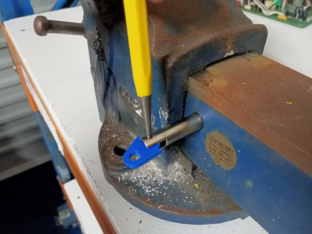
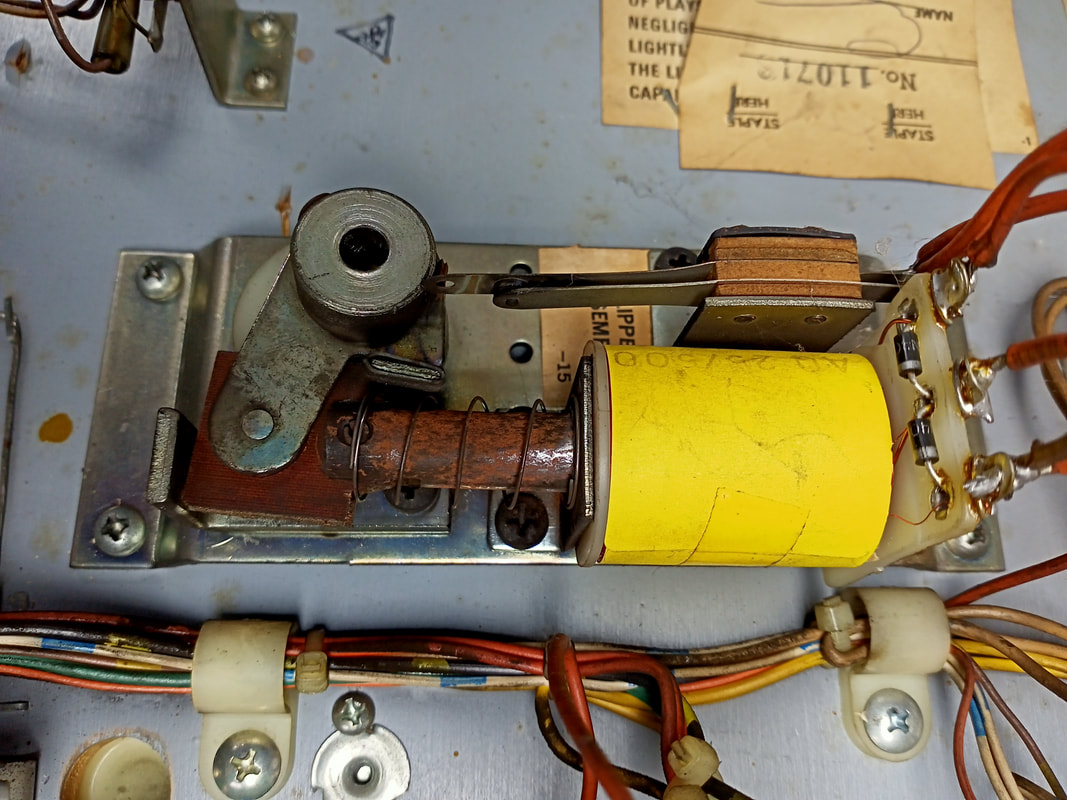
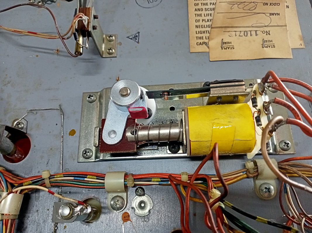
The slingshots on this game had a number of problems which were causing them to lose power. Each slingshot activation would only weakly impact the ball, which led to some fairly lame slingshot action in the lower half of the playfield. So, the first step to troubleshooting was to take the assembly apart and look for issues with each individual part. The first problem I noticed was the shape of the kicker arm assembly. The top part of the arm was bent, such that the plunger would bind when entering the coil. Fixing this was easy - a quick bend in the vice got it back to straight again.
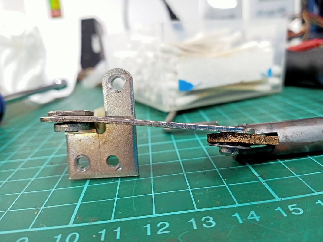
Even after straightening the kicker arm, the slingshots were too weak. There appeared to be a lot of slop in the assembly. Looking at the plunger and link, I found that the holes in the link had been stretched out, which would potentially explain the loss of power. Unfortunately, replacement links (part no. P-7373) do not exist. Neither do complete plunger and link assemblies (part no. ASE-2586). So, I decided to replace the links with the nearest replacement I could find, which were standard Williams slingshot links (part no. 03-8085, RTBB, PSPA, Austral Amusements). The dimensions of these links are a little different to the originals, but close enough. So, I removed the roll pins from the original plungers, inserted the new links, then used a vice to drive the roll pins back into position. The new links aren't exactly the correct size, however they do work, and the slingshots work quite well with them. The part which is more difficult to source on these assemblies is the plunger itself, which is not available anymore. An interesting discussion on Pinside discusses some alternative replacement parts. Luckily, since the plungers were in reasonable condition after a clean, they could be used again. Pop bumper refurbishment
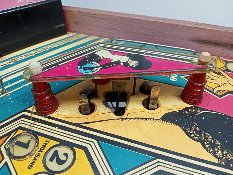
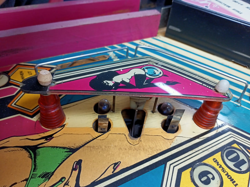
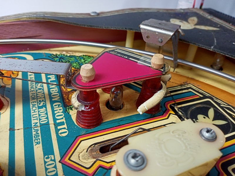
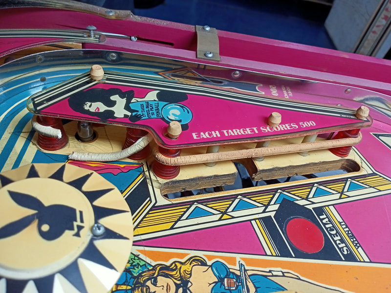
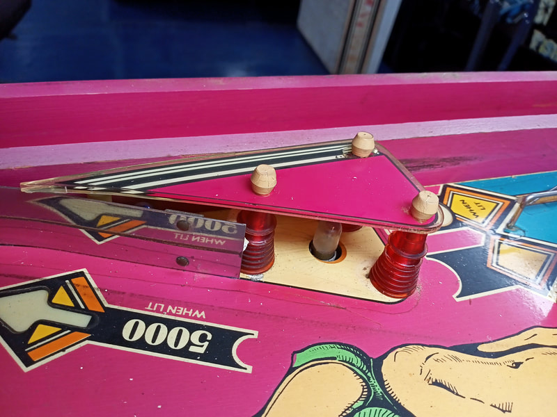
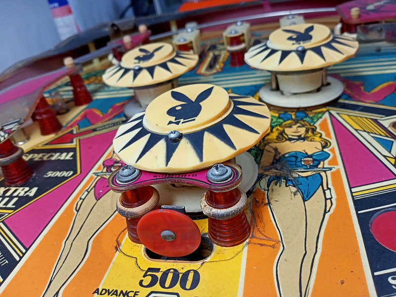
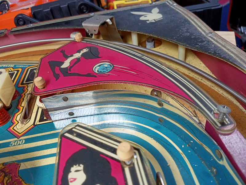
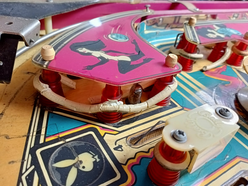
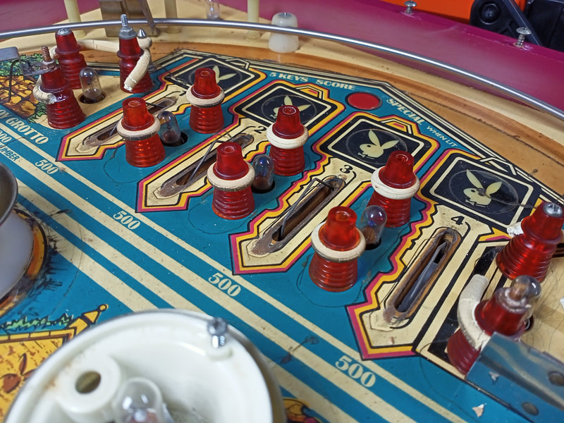
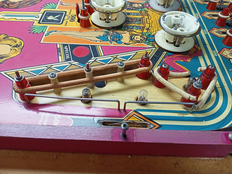
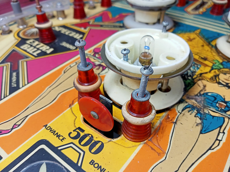
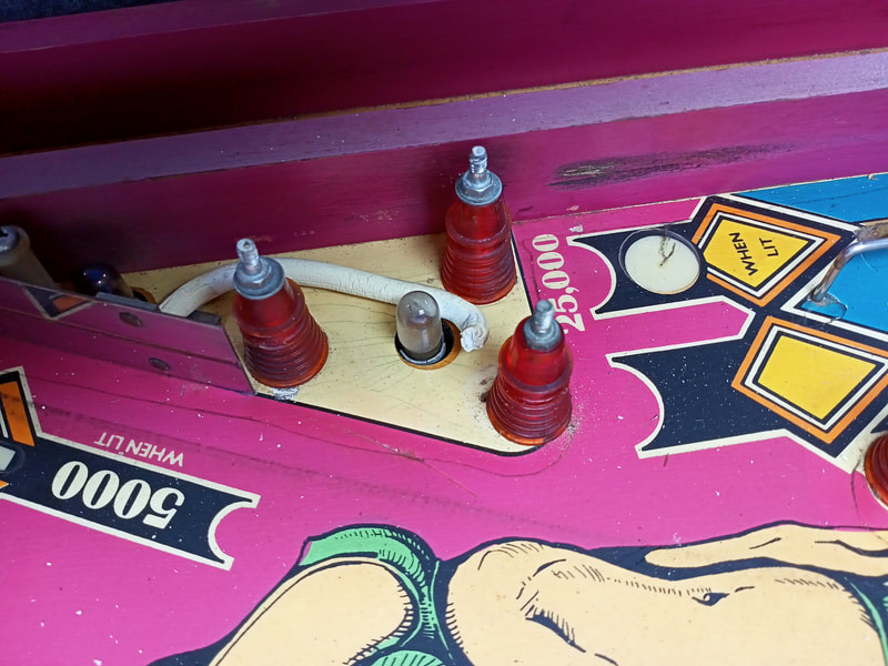
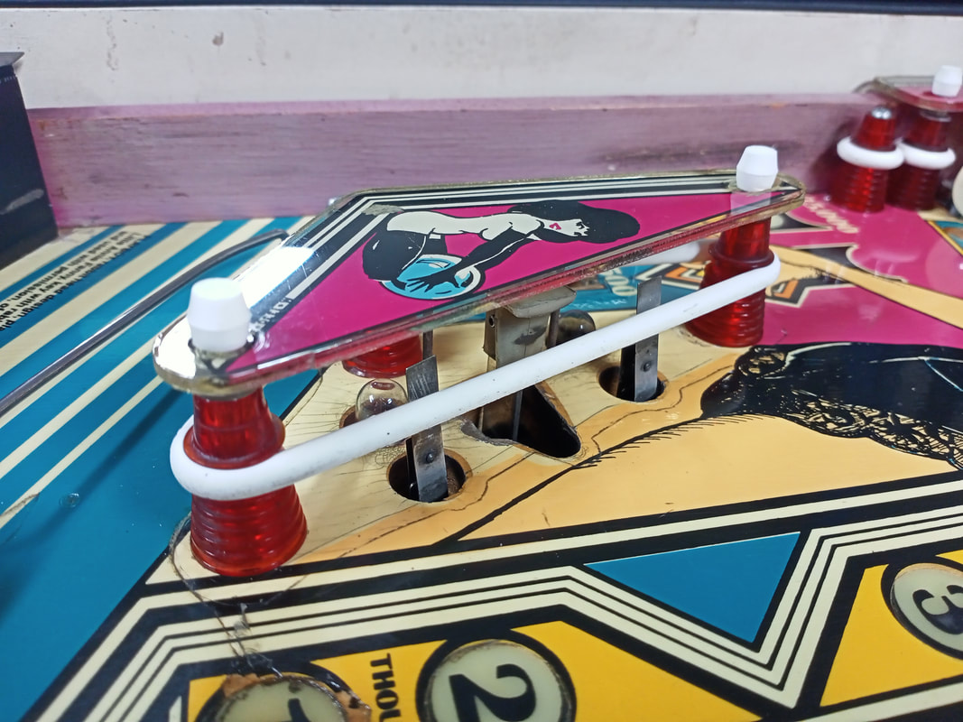
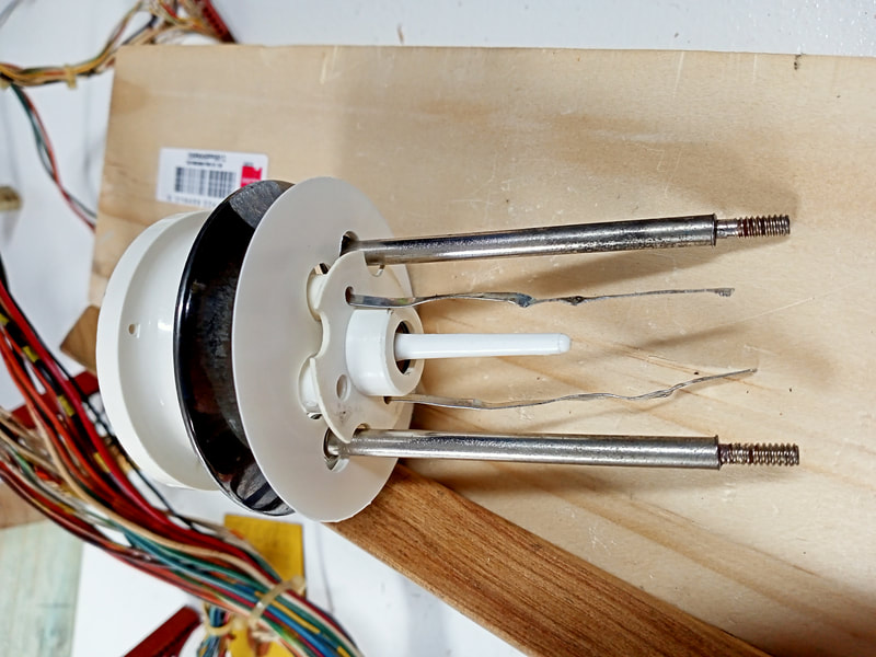
The pop bumpers on this game were in typical 1970s game condition: beaten, broken, and abused. Each pop bumper got entirely rebuilt with new sleeves, spoon switches, pop bumper bodies, and skirts. Here's a tip for pop bumper reassembly on Bally games. When reassembling the bumper one piece at a time, it can be a pain to hold everything in place while trying to thread the lamp leads through the other bumper parts, the playfield, and then the mechanism under the playfield. So, to make this process easier, I like to completely assemble the above-playfield pop bumper mechanism and simply feed the lamp leads through the playfield at the same time as the rest of the assembly. Then it's simply a matter of screwing the body to the topside of the playfield, and fastening the rod and ring assembly.
Although I stuck to incandescent lamps for this machine, one place where I like to place LEDs is inside the pop bumpers. This is because LEDs have a shorter profile, allowing them to fit more nicely into the constricted space of the bumper body, and they emit far less heat. Most of these bumper caps are brown or melted due to exposure to prolonged heat from incandescent lamps, so installing LEDs is a good idea to protect your bumper caps from further damage. The end result is very hard to differentiate from incandescent lamps if using warm white LEDs. It appears reproductions of Playboy bumper caps are no longer available (and those that were available were dubious quality). Only one source seemed to have stock at the time of writing (Classic Arcades). However, Pinside user Jester had the idea of using blank starburst caps (Marco, PB Resource) and simply tracing the Playboy bunny logo onto them. Genius idea! Circuit board upgrades
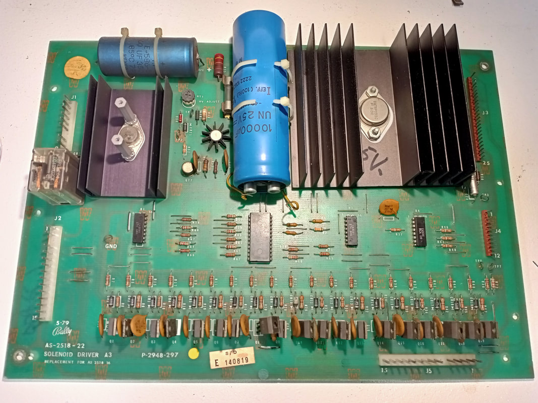
With the boards in this game being in mostly original condition, there was a bit of work to be done in terms of reliability upgrades. Apart from installing a new rectifier board and replacing header pins on the lamp driver board (discussed in one of the sections above), the solenoid driver board needed attention. Some work had been done on this board in the past, as the large capacitor at C23 did not appear to be original - it was way too big for the board. Still, the board operated without issue in the game and all of the coils appeared to work properly. So, this was more about bullet-proofing the board for years of future use.
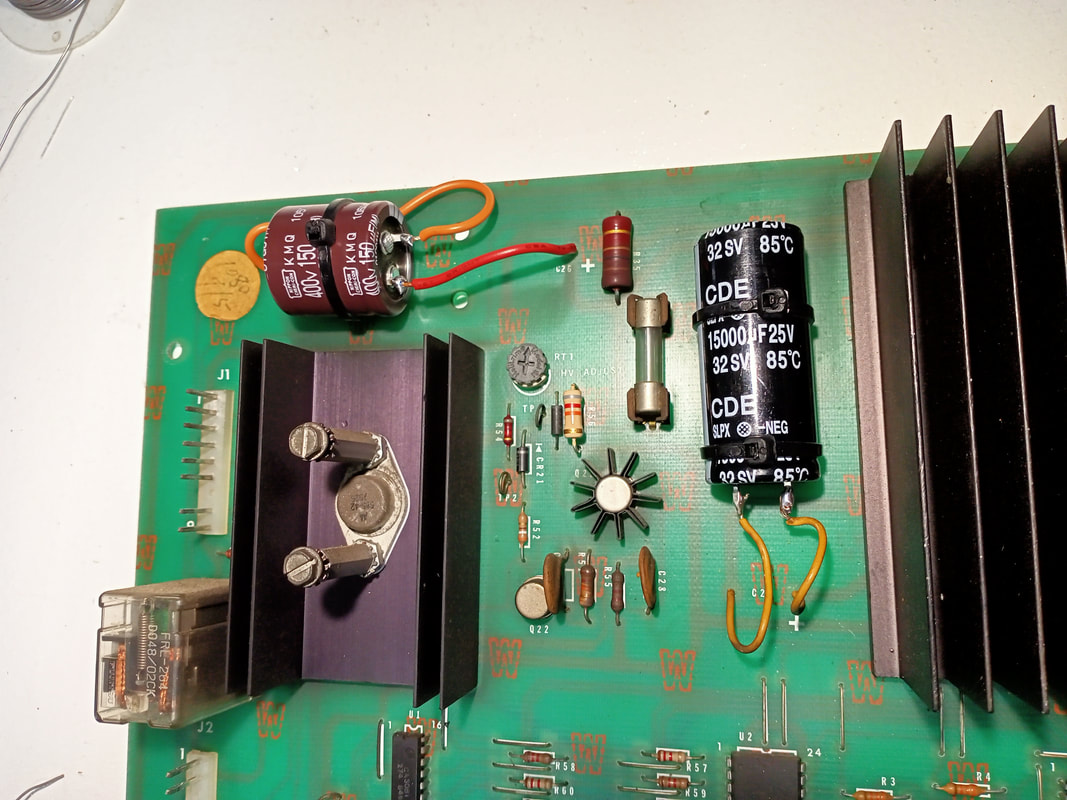
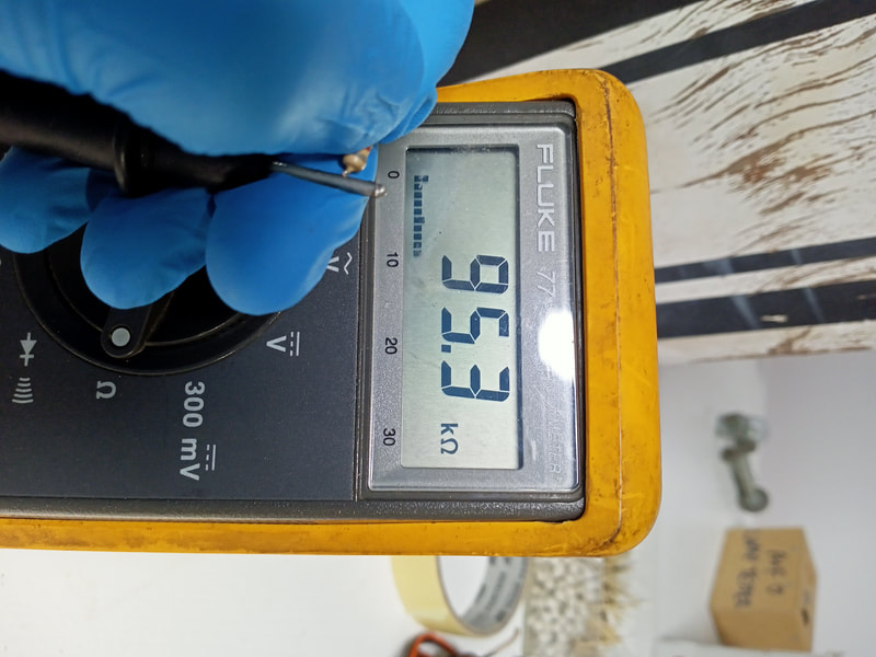
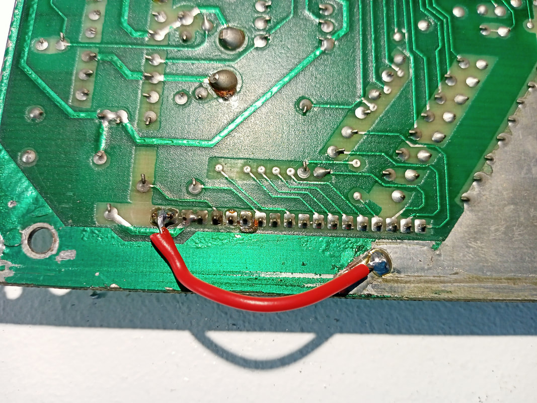
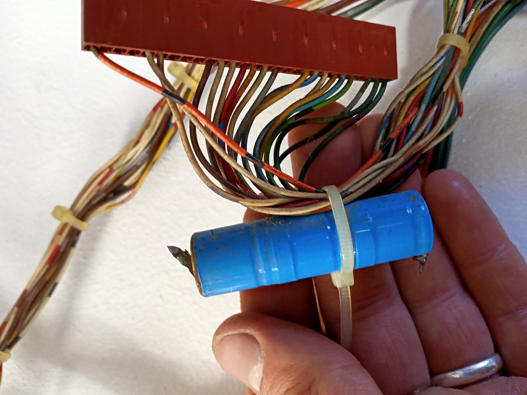
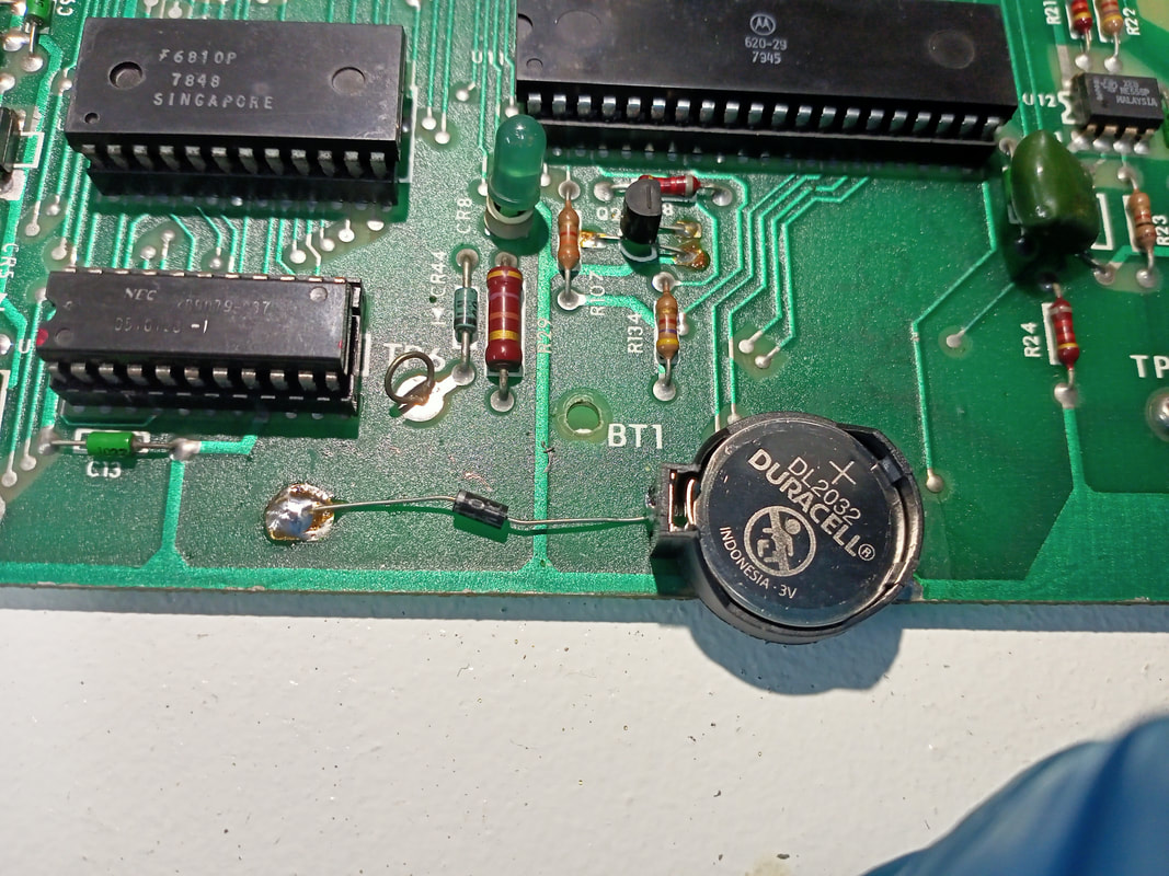
For this rebuild, the basic advice on Pinwiki for rebuilding the solenoid driver board was followed. This included removal and replacement of the large capacitors at C23 and C26. The larger cap at C23 can be replaced with any value between 11,000 and 16,000uF. I use 15,000uF, 25v capacitors as these are common on Williams driver boards as well (RS Components). For C26, a replacement of 150uF with a voltage rating of at least 350v will suffice (RS Components). This one looks a little weird because it is quite stout and short, but it works, so that's the main thing. You'll need to connect jumper wires as I have below if you don't use an axial capacitor with leads coming out either end. These capacitors are expensive, so shop around a bit when you buy to see if any equivalent capacitors are cheaper. Then, I checked all of the components in the high voltage section to make sure they were still in good condition. One of them was not - the resistor at R56. This resistor has a nominal resistance of 82k ohms, but was measuring 95.3k ohms! Way out of specification. So, this one was replaced (Jaycar). Finally, a couple of mods were done to the underside of the board. The negative leads of C23 and C26 were both tied to ground, to ensure that these caps always have a reliable path to ground instead of relying on long traces across the board and through connectors. A jumper wire was installed to connect test points 1 and 3 (5v test points). This ensures that the 5v signal is always present on the board, and does not travel off the board via the J3 connector, where it can potentially be lost or degraded through a poor crimp or solder joint. Finally, all of the header pins and connector crimp terminals were checked for any corrosion or other issues. Surprisingly, they were all in good condition, and there was good continuity from the connectors through the board. So, I elected not to replace these in this case. However, this is always a good idea for better reliability. And with that, the solenoid driver board was done! Next was the MPU board. There were two small modifications to be done here. First, a ground modification. A jumper wire was installed to connect pins 18 and 19 of J4 to the adjacent ground trace. Since these pins only connect to ground on the component side of the board originally, they can develop a poor connection, especially if there is any corrosion in this area. Thankfully this board was not corroded at all, but the jumper is a good idea regardless. Next, battery replacement. Fortunately, some switched-on operator had removed the original battery from the MPU board and had connected to it to the wiring harness lower down in the backbox, using long wires to connect it to the original terminals. This battery was long dead, so another solution had to be installed. I opted for a CR2032 battery (Bunnings) in an appropriate holder (Jaycar). There are many other solutions which are explored on Pinwiki, however I like the CR2032s for their simplicity and user serviceability. Keep in mind that you will need to install a blocking diode (I used a 1N4004, Jaycar) to prevent the battery from being charged by the MPU. Connect the banded end of the diode to the negative terminal on the board, and the non-banded end to the negative terminal of the battery holder. In this case I mounted the positive terminal of the holder to the positive through hole on the board, drilled a small hole to insert the negative terminal of the holder through the board, and then inserted the blocking diode (non-banded end) through the new hole as well. Then I soldered everything in place on the underside, locking the holder in position. This seemed pretty stable and the battery could be removed and inserted without stressing the connections. So, all good to go! Playfield switch adjustments
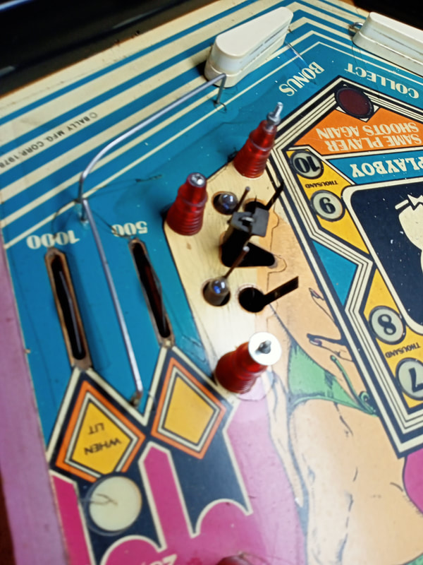
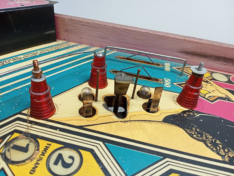
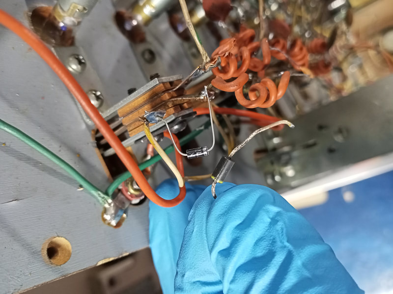
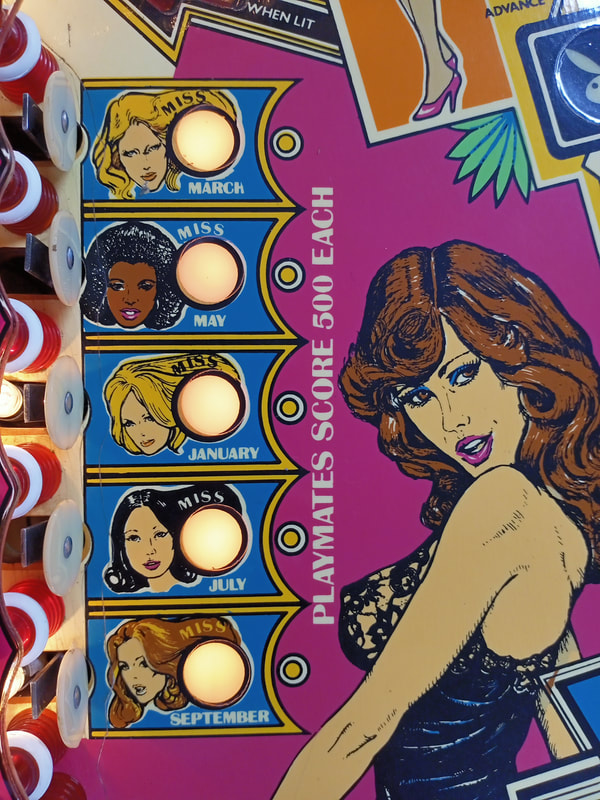
There were problems with various switches on the playfield. First, the bottom standup target (Miss September) did not register at all. The switch itself seemed to be intact, so I took a look under the playfield. All wires were connected as expected and nothing seemed amiss. With the multimeter, I confirmed that the switch blades were actually making contact when the switch was hit. Next was to check the diode. This was where the problem appeared to be. The diode across the switch lugs returned an odd reading - about 0.4v instead of the 0.5 or 0.6v the other switch diodes were reading. So, I replaced it. Bally used 1N4004 and 1N4148 diodes on all playfield switches. I generally replace these with beefier 1N4007 diodes (eBay). Once the new diode was in, the switch worked properly.
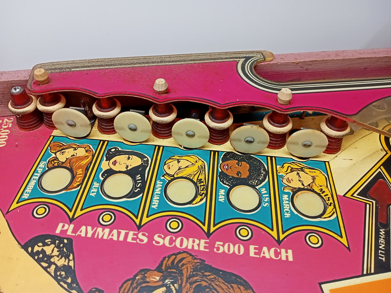
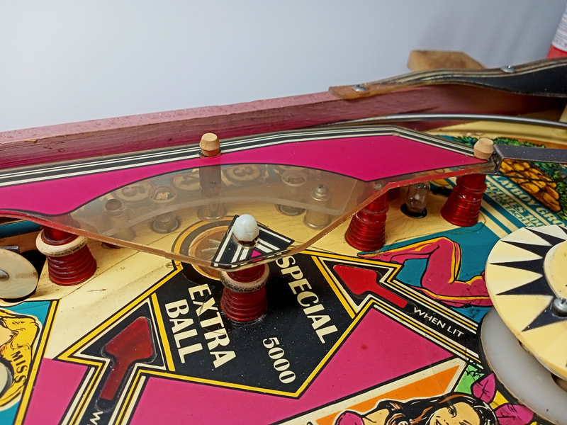
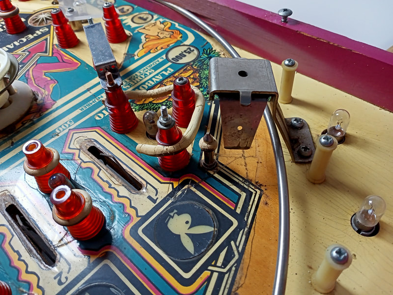
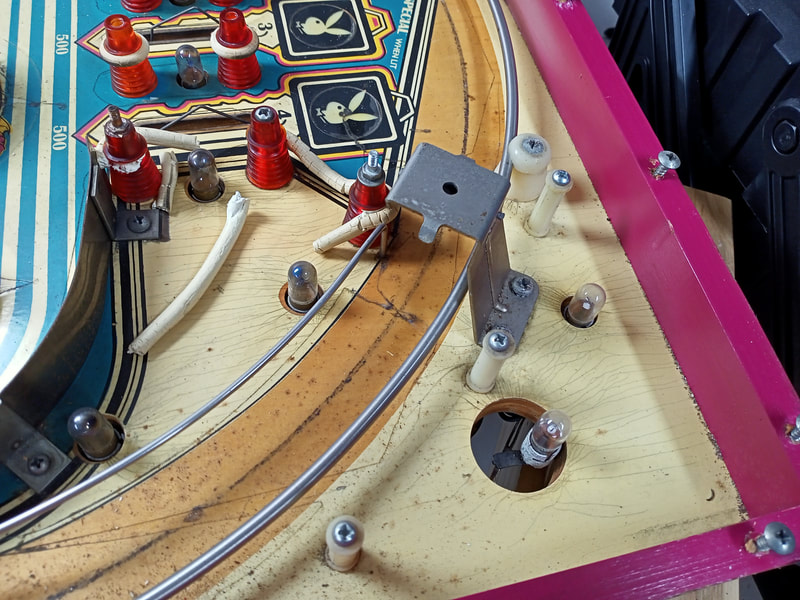
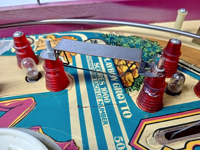
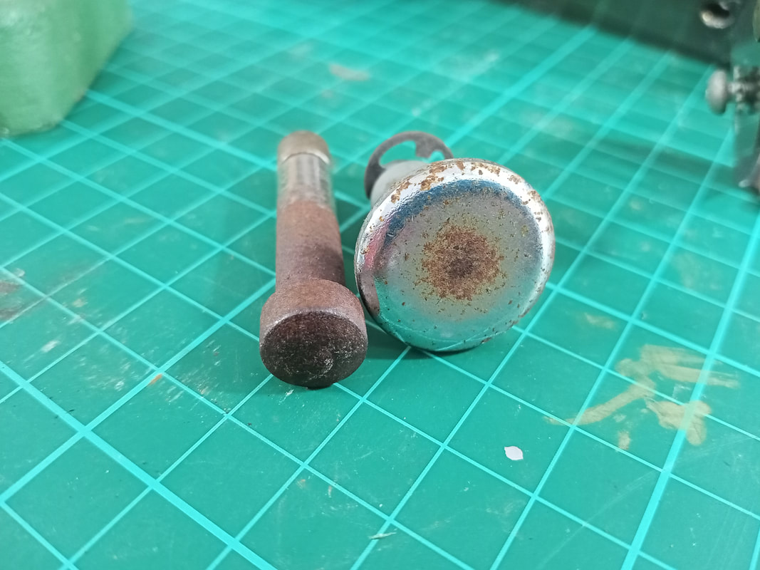
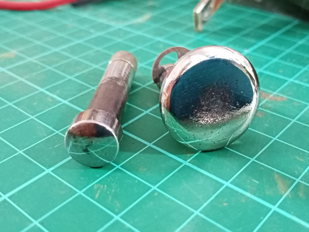
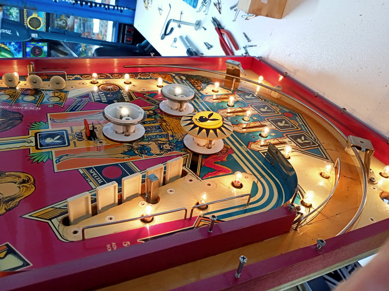
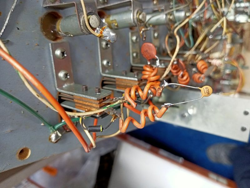
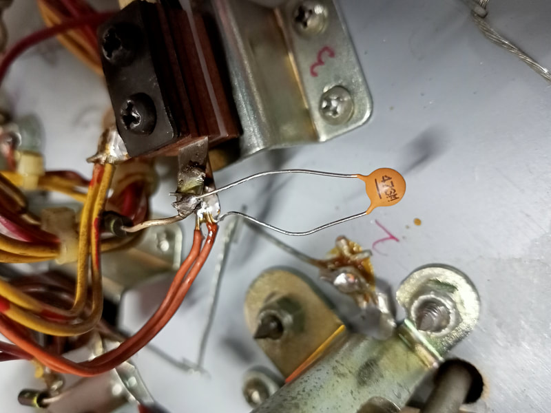
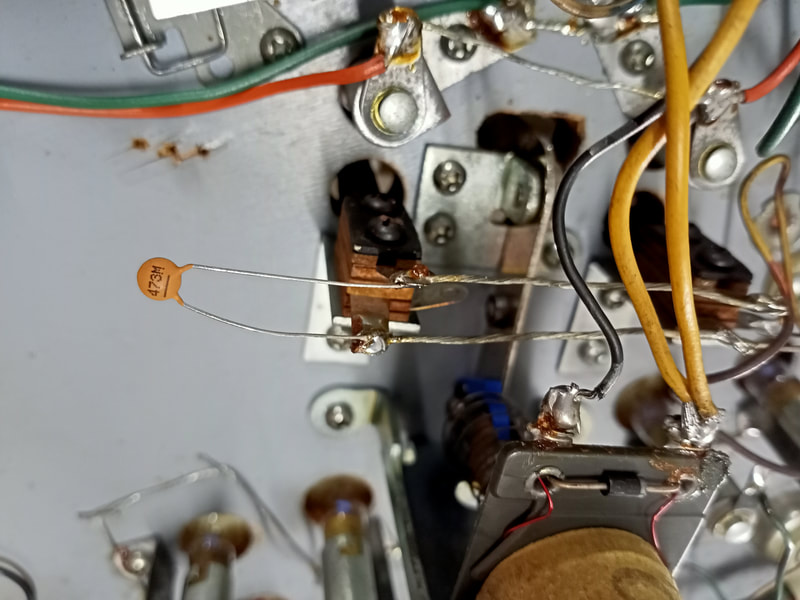
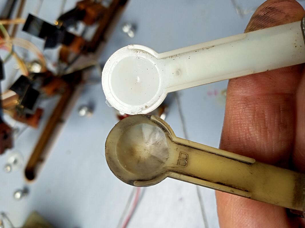
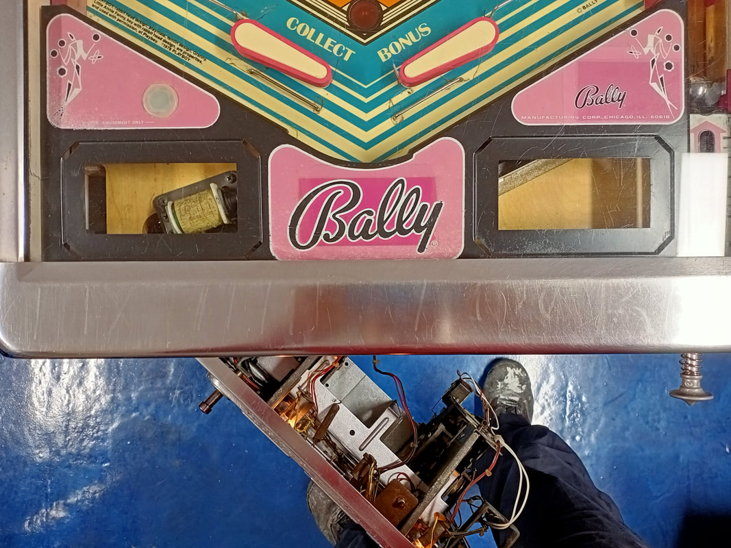
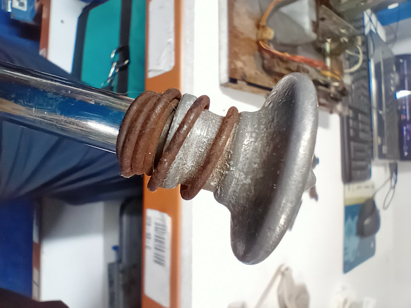
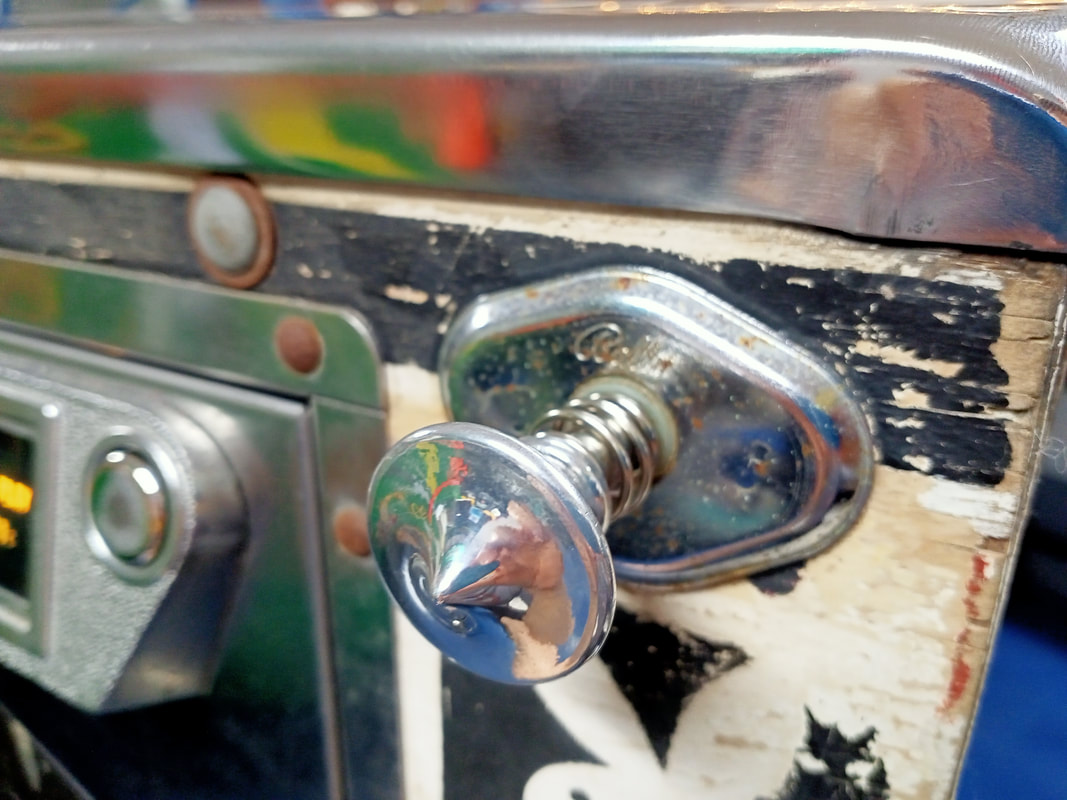
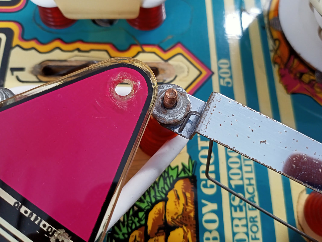
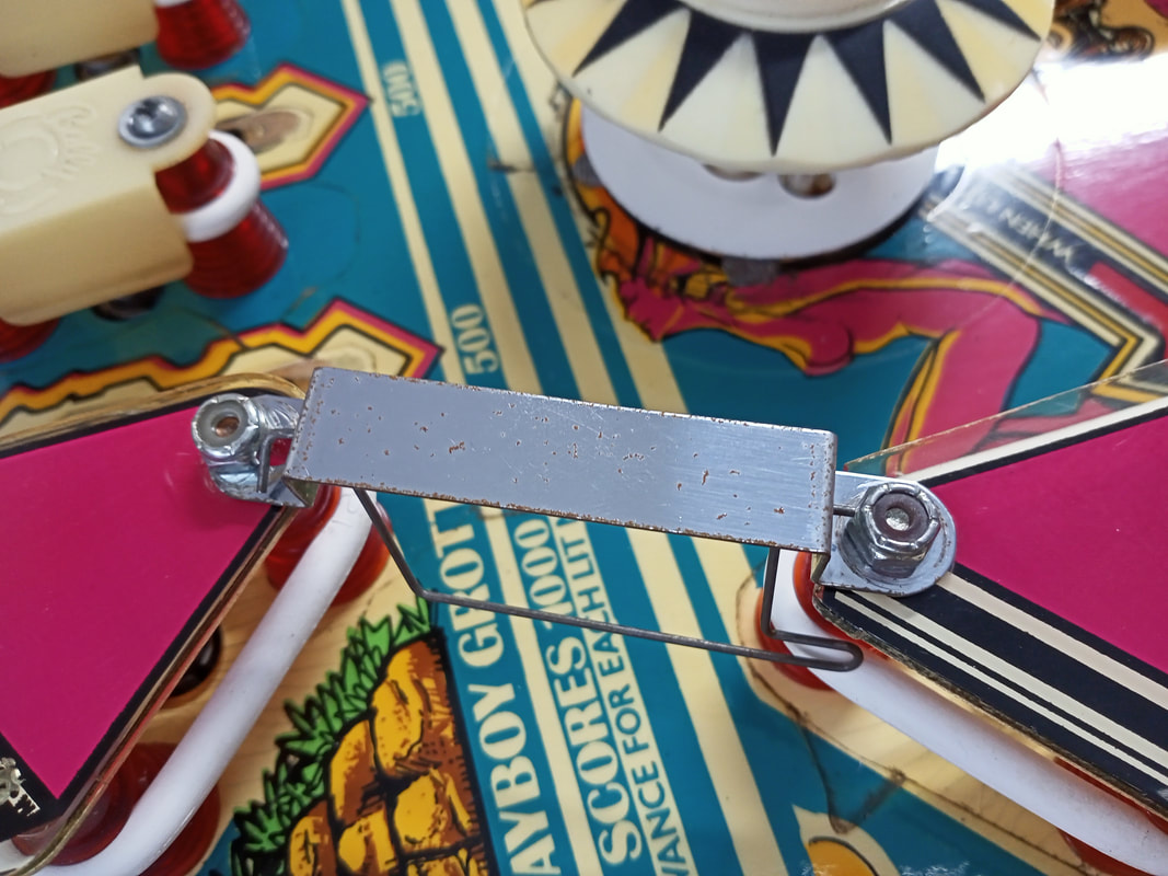
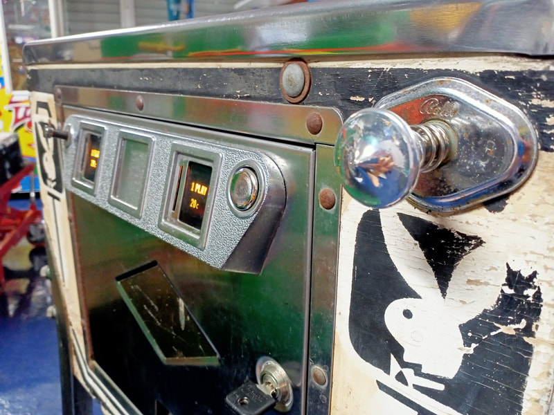
More switch issues followed. You may notice that some switches on Bally games have small capacitors attached. There is a good explanation for this on Pinwiki. Basically, whenever a switch is hit, the MPU must be able to scan all switches in the switch matrix quickly enough to "read" the switch hit before the switch closes again. This may not be possible when a switch is hit very briefly, and the MPU in unable to "see" the switch as it cannot scan the matrix quickly enough. The capacitor stores a small charge and extends the length of time that the switch is visible to the MPU. Otherwise, these switches may do nothing when hit, especially if they are hit very rapidly. So, capacitors are used on switches such as slingshot and pop bumper switches, which are often only closed for very short amounts of time. Many of these capacitors were missing from the playfield, including one pop bumper capacitor (snipped off), one standup target capacitor (broken), and both slingshot switch capacitors (none present at all). Since slingshot switches are connected in parallel, only one capacitor is needed per slingshot. Keep a large stock of 0.0047uF (47nF) capacitors rated for at least 16 volts for this purpose (Jaycar). The last switch issues I had were with a couple of the pop bumper switches. These switches were not activating consistently, and this was after I had checked there were capacitors installed on each switch. One bumper worked fine, while the other two did not. This appeared to be more of an issue with how the switch was actuated rather than an electronic issue with the MPU or wiring. I only managed to figure out the root cause of this issue when I tore the pop bumpers down to rebuild them. The two bumpers with dodgy switches had what looked to be original pop bumper spoons. These spoons actually had grooves worn into them, such that the base of the bumper wafer/skirt would sit and "lock in" these grooves rather than move freely across the entire face of the spoon. This caused the switches to actuate inconsistently, unless the bumper skirt happened to be pushed along one of the existing grooves. Replacement of the spoons got the switches activating reliably again. There is one thing to note when you refurbish the pop bumpers. When you replace the plastic spoons under the playfield, you may have difficulty getting them onto the switch stack after removing the original spoons. This is because the holes in the original spoons (part no. C-921) seem to be a smidge larger than those on reproduction spoons (RTBB, PSPA, Mr Pinball, Austral Amusements, Scribbly Gum). You will need to enlarge them slightly. The easiest way to do this is with a drill. While the holes are imperial sizes, a 4.8mm drill bit works just fine. Reassembly While this particular customer did not have a lot of money to spend on this machine, there were a few bits I couldn't just leave in their original state, so I spent some extra time just to make them look a little nicer for him. Apart from the coin door buttons and shooter rod, the lockdown bar warranted special attention. At some point in the past, somebody had actually engraved the delightful words "FIX THIS FUCKER" into the lockdown bar. I guess that's what happens when operators don't maintain their games on site! The engraving was a little hard to see but in the right light, the words could be made out. This took a little bit of time on the polishing wheel to remove. I used a sisal polishing wheel to buff out most of the gouges (black compound) followed by some time on the stitched rag wheel (green compound). All in all I probably spent at least 30 minutes on the lockdown bar to remove the words as best I could. And of course, the lockdown bar looked nice and shiny by the end of it, too! Of course, the shooter knob got a nice polish as well. When reassembling the playfield plastics, you may notice some issues with the wire gate which allows balls into the grotto shot (left side of playfield). The wire gate allows balls into the left lane but stops them from coming back out. This wire gate assembly was initially installed underneath the playfield plastics but I found that this interfered with the operation of the gate. The gate would strike the plastic and wouldn't be able to move through its full range of motion, often staying in the "up" position. Instead, install the gate assembly on top of the playfield plastics. This allows the wire gate to move freely. Of course, you can't complete a restoration of a Bally game without a new flipper kit (RTBB, PSPA, Austral Amusements). The original flippers were rusty and barely flipped, so once the coils were checked for appropriate resistances (no dead shorts on either winding), the old parts were taken out and new parts were put in. Don't forget to install the new end-of-stroke switch, as this makes a noticeable difference to flipper power when new compared to old and pitted. The few spare screws in the flipper kit were also handy as some were missing from the assembly. That was about it for this machine. Reassembly went fairly smoothly and there weren't really any issues encountered afterwards. Apart from the LEDs installed in the pop bumpers, the machine was kept original with incandescent lamps. White rubber rings were installed on the playfield, which look really nice when contrasted with the pink on the playfield. Interestingly, although red flipper rubbers were installed, these rubbers looked more pink in colour than red, which suited the colour theme of the rest of the playfield perfectly! I think I've breathed some new life into this game. But it doesn't matter what I think - all that matters is that the customer is happy with the end result. And he was! He had last played this machine a decade ago, and now it was finally in the condition he remembered it to be in when he first got it. This machine will be playing and providing joy for years to come!
5 Comments
Bud
14/9/2023 05:28:26 am
I have one if these and I need to replace the entire head of the machine due to rot. Any suggestions on someone that can do this? Can't find anything online about refurbished ones or anyone making them. It's final piece to get my Restoration underway
Reply
Terry L. Pope
17/10/2023 08:06:13 am
I need a refurbished/updated pcb for my Playboy machine. Part number P-2948-296. Please LMK condition and cost.
Reply
Hi Terry,
Reply
Leave a Reply. |
About
Here you will find logs of our pinball and arcade machine restorations, repairs, discussion about general pinball and arcade topics, as well as recounts of our random pinball adventures.
Check back regularly for updates! Blog updates
Archives
May 2024
Categories
All
Donate

Running this website is a hobby for me (just like pinball!). I like being able to show off my restoration work so everyone can learn from it and potentially fix their own machines. If you enjoy reading the site's content or it has been helpful to you, please consider donating to offset some of the website's operating costs. |




 RSS Feed