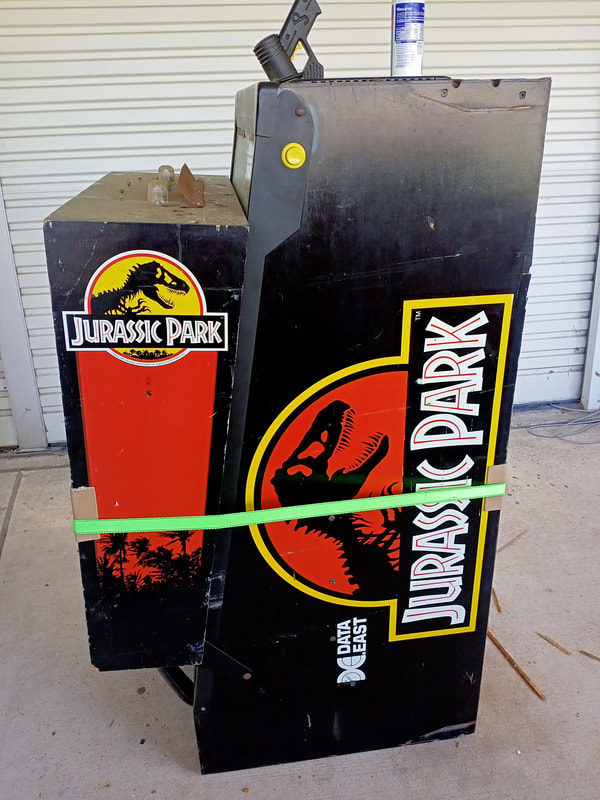
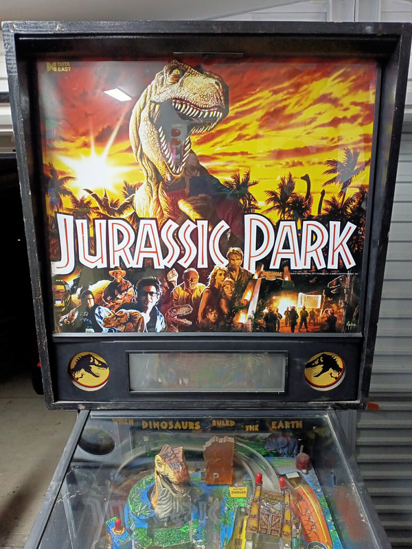
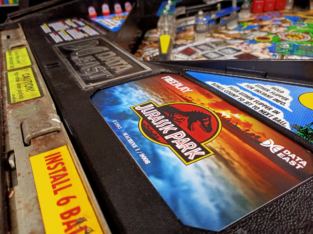
 I haven't had to do a full restoration on a Data East machine in a little while, so it was about time one came around. Enter Jurassic Park! This machine came from a customer who had this machine sitting in their garage. They had just moved house and wanted the machine brought back into playing condition so they could play it in their new house. As expected, the Jurassic Park was much older than the house, and was also in much poorer condition. The game did start up and enter attract mode, but a lot of playfield features did not work and a lot of parts were broken. This was going to be a full-on restoration, and I wanted to add a few little touches to really bring the machine back to its former glory. So, if this pinball machine was 65 million years in the making, then I was in it for the long haul with this restoration. Initial condition report (click on sections below to view details) Cabinet
Poor condition overall.
Above playfield
Average condition overall.
Under playfield
Average condition overall.
Electrical
Poor condition overall.
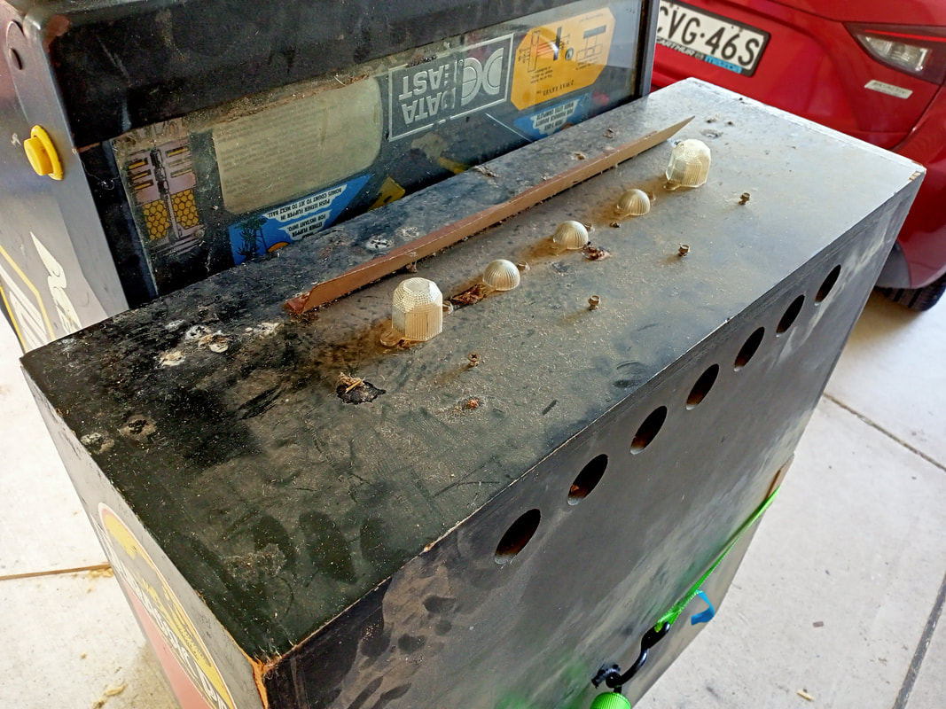
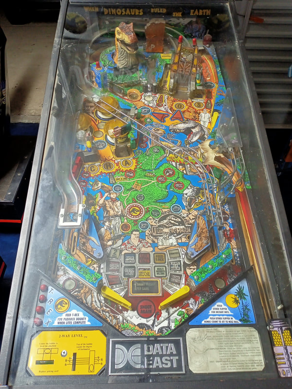
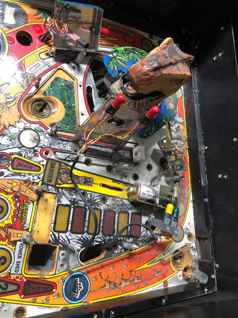
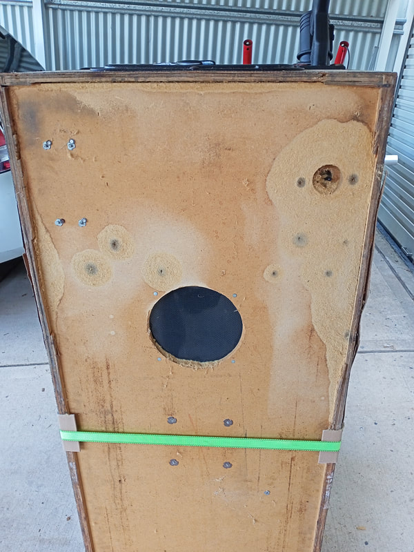
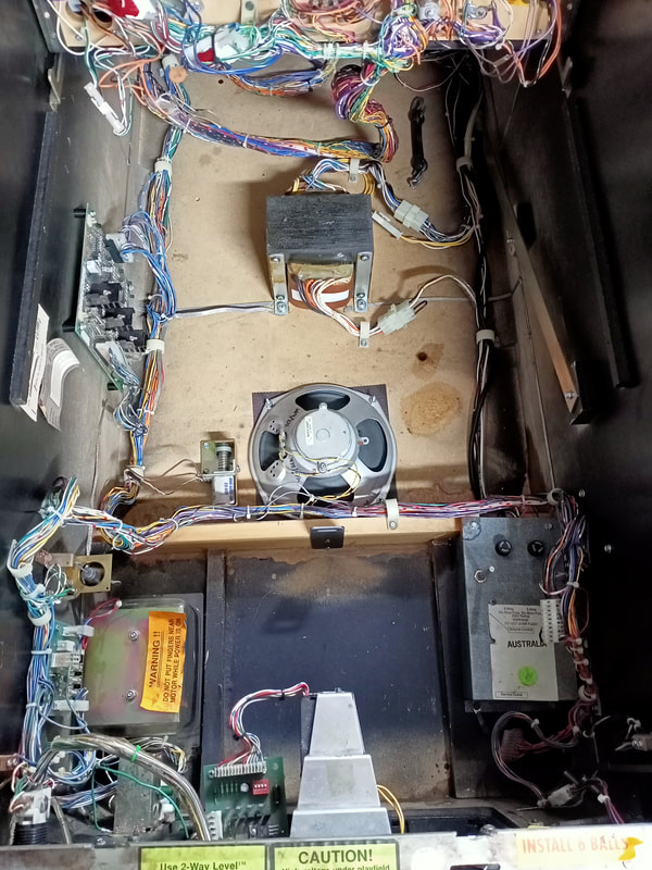
The first thing that I noticed when I inspected this game for the first time was the amount of swelling and rot which had affected the MDF cabinet. In particular, the underside of the cabinet was bulging in several places, particularly around the power switch, where moisture had penetrated into the MDF. The result was a very flaky and soft substrate which would need repair if only to prevent you from getting splinters every time you went to turn the game on! The inside of the cabinet was similar, with the crossbeam that separates the coin box from the speaker having swelled and split after soaking up water for an extended period. It's a shame when these cabinet bases get wet, as most manufacturers of the era used cheaper (and weaker) MDF for the base, even though plywood (as used for the cabinet sides) maintains its structure a little better when affected by moisture. The playfield looked fairly ordinary, with a lot of broken plastics, some damage to the timber around the scoops, a lot of dirt and dust everywhere, and most playfield mechanisms in dire need of a good clean and service. There were some obvious issues with the circuit boards, too. However, despite this, the game did boot up successfully. That was a good start, but a lot of work was needed to make sure it would keep booting up successfully. Disassembly I would say Jurassic Park is one of the simpler dot matrix games when it comes to playfield disassembly. There are only a couple of ramps to disassemble: the wireform ramp which leads to the right inlane (secured by a single nut on the right slingshot) and the main plastic ramp. The main plastic ramp requires disconnecting some flashers, lamps and switches. You can find these in the back left corner as well as to the right of the ramp entrance. There are holes in the playfield which the wires are routed through. The main ramp is secured by a screw on the left slingshot, a screw in a metal post halfway up the left side of the playfield, two screws on the playfield back panel, and two screws which secure the ramp flap to the playfield. Once those are all undone, it should slide upwards and out. The T-Rex looks like a daunting mechanism to disassemble but is is not too hard; it just needs to be done in a specific order. There are some instructions on how to take this assembly out of the game in the T-Rex assembly refurbishment section below. The ramps and the T-Rex are the main assemblies on the playfield; everything else is quite simple to take apart. Again, I have to express my appreciation for Data East pop bumper assemblies, which you can unscrew and remove from the playfield in one piece - brilliant! Some images of the disassembly process are below. After disassembly, the game went through my standard restoration process to get it playing and looking like new. During the restoration process, I dealt with a number of issues, described below. Tips & Troubleshooting (click on sections below to view details) Cabinet timber and small metal part repairs
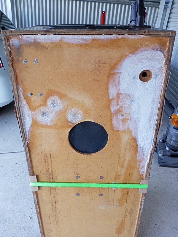
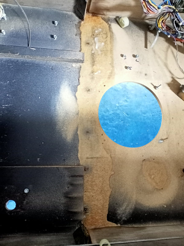
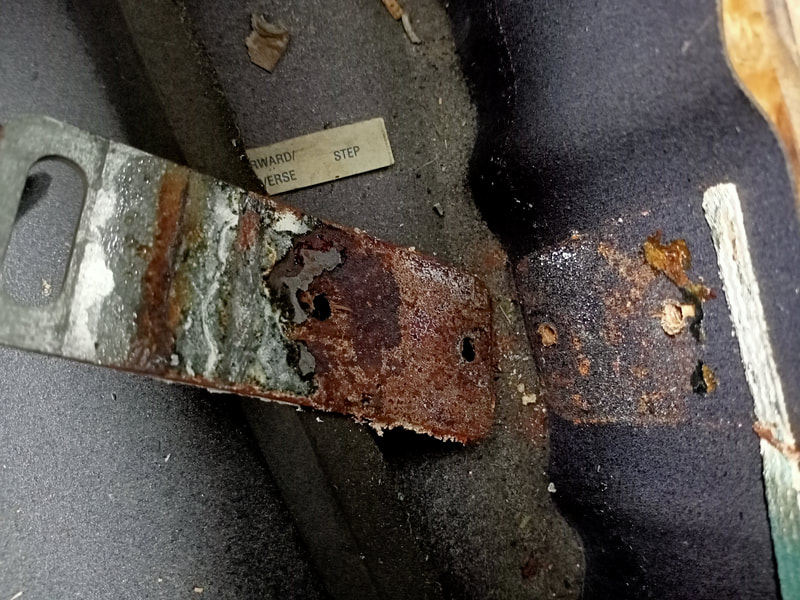
At some point, water had leaked into the cabinet, or the cabinet had been placed on the floor without legs and the floor subsequently got wet. The front right side of the cabinet, in the location of the power switch, was where most of the damage occurred. Definitely not a good place to have water, as 240 volts is present at the power switch. In fact, the mounting plate for the power switch was very rusty, indicating that the water did rise up a into the cabinet.
I only really saw the extent of the damage to the cabinet floor when I got the game home and stood it up on its end. The affected areas were seriously swelled, and touching them would cause the MDF to fall off in clumps. Unfortunately, MDF is basically ruined once it gets affected by water, so the only two options were to repair the damage and seal it in as best as possible, or replace the entire cabinet floor. Replacing the cabinet floor is a huge job, and would have added significantly to the labour of the job. The owner wasn't too keen on going that far, and was happy to have the damage repaired as best as possible, so that's what I tried to do. 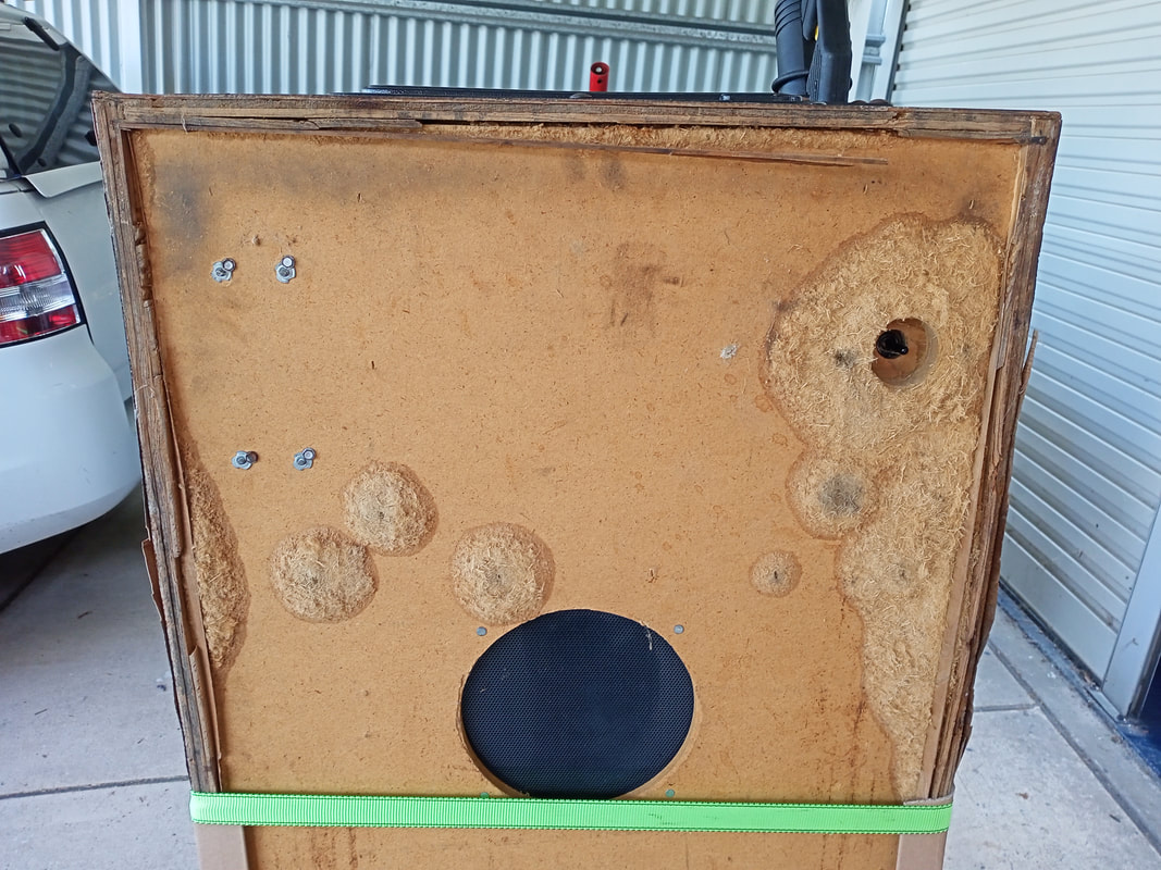
Swelled, water-damaged sections of the cabinet base.
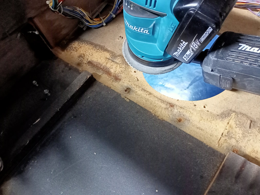
First step was to get rid of all of the swelled, flaky MDF fibres. I did this before I even moved the machine into the workshop, because this job is extremely messy. I busted out the orbital sander, and used a fairly coarse grit (80) to make a quicker job of it. Grab a pack of multiple grit sanding pads so you can start coarse and finish a little finer (Bunnings). Sand all affected areas down so they are flush with the rest of the cabinet. Try as you might, the final finish will never be as smooth as unaffected parts of the cabinet. Small MDF fibres will always peel off, but you need to make sure that it is sanded down to the point that fibres no longer come off in huge clumps, or with just a light touch. I had to break out the sanding block to get into the tighter corners at the cabinet sides, but otherwise the orbital sander made this a relatively quick and easy job. Once it is smooth, it needs to be sealed so that loose fibres are locked in. You can use a few products for this, such as polyurethane, resin, or shellac, but I've had good success with standard PVA wood glue (Bunnings). Simply coat the exposed areas with a generous layer of glue and leave to dry.
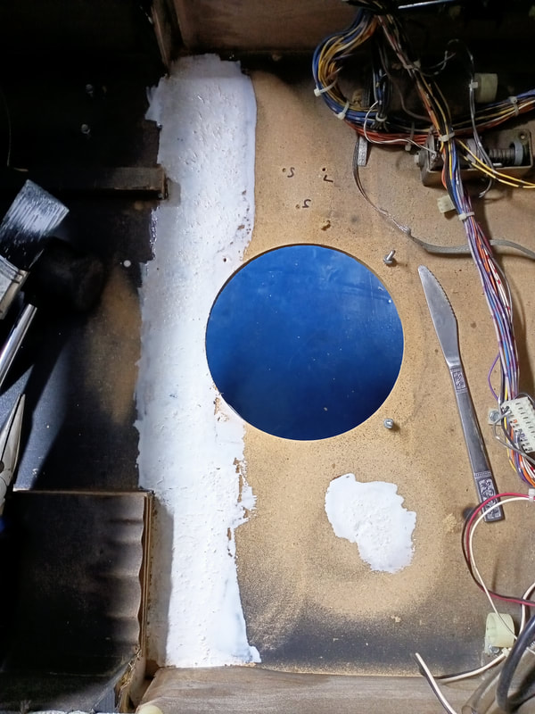
Once the glue dries hard, the repaired areas are good to go. The final finish is quite rough compared to the original MDF. However, it is strong enough to hold the remainder of the cabinet together and will stop MDF fibres going everywhere every time you touch the underside of the cabinet when turning the game on. In the photo below I've also sealed the perimeter of the base with liquid nails adhesive (Bunnings) to give a little more strength to the cabinet. 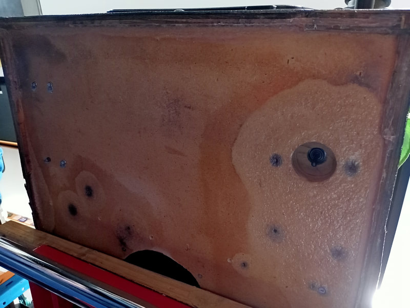
Final finish after glue has dried.
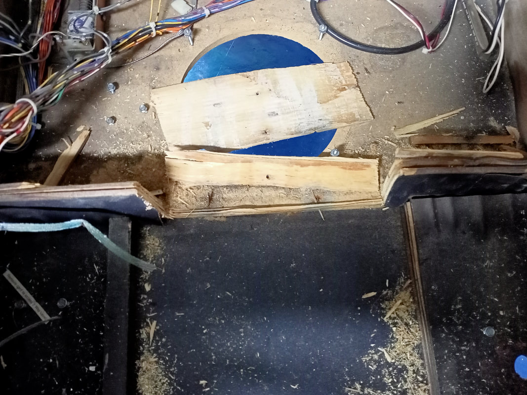
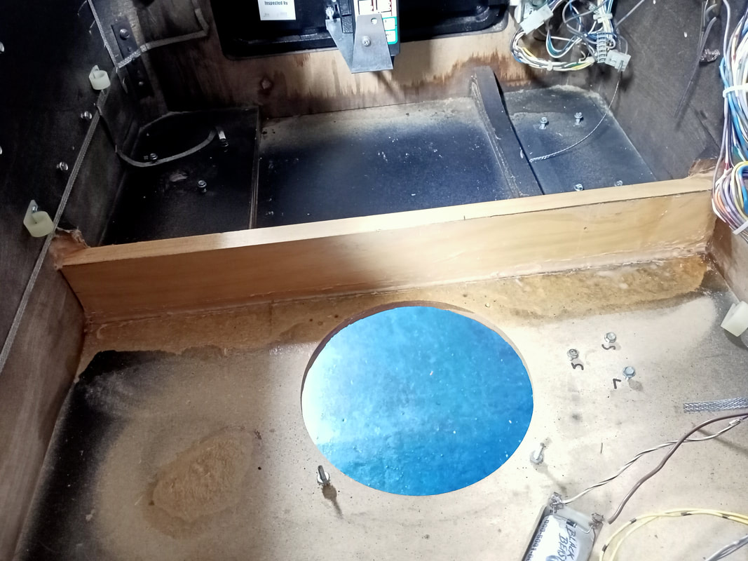
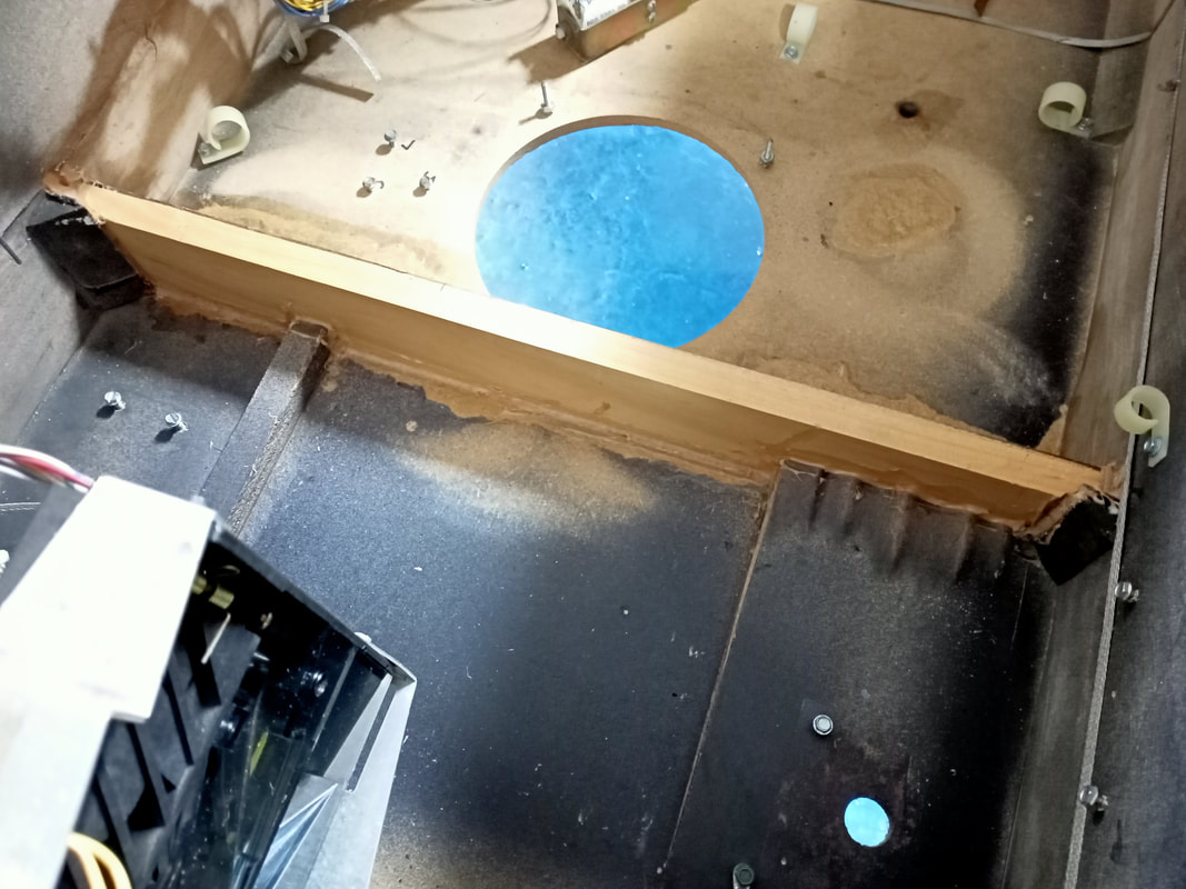
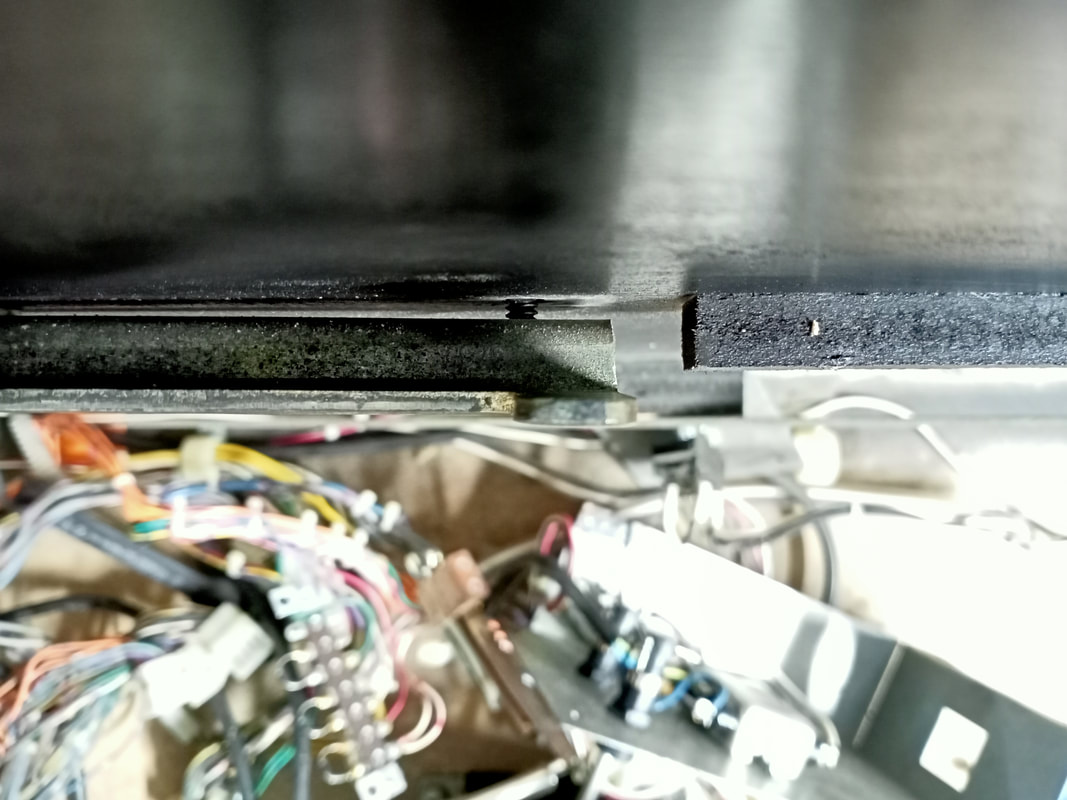
The next area of water damaged timber was inside the cabinet. The crossbeam which separates the coinbox from the speaker was completely destroyed. It had swelled up to the point that each layer of ply had separated from the rest. Note that while Data East used MDF for the cabinet floor, all other cabinet timber (i.e. the crossbeam) is plywood. 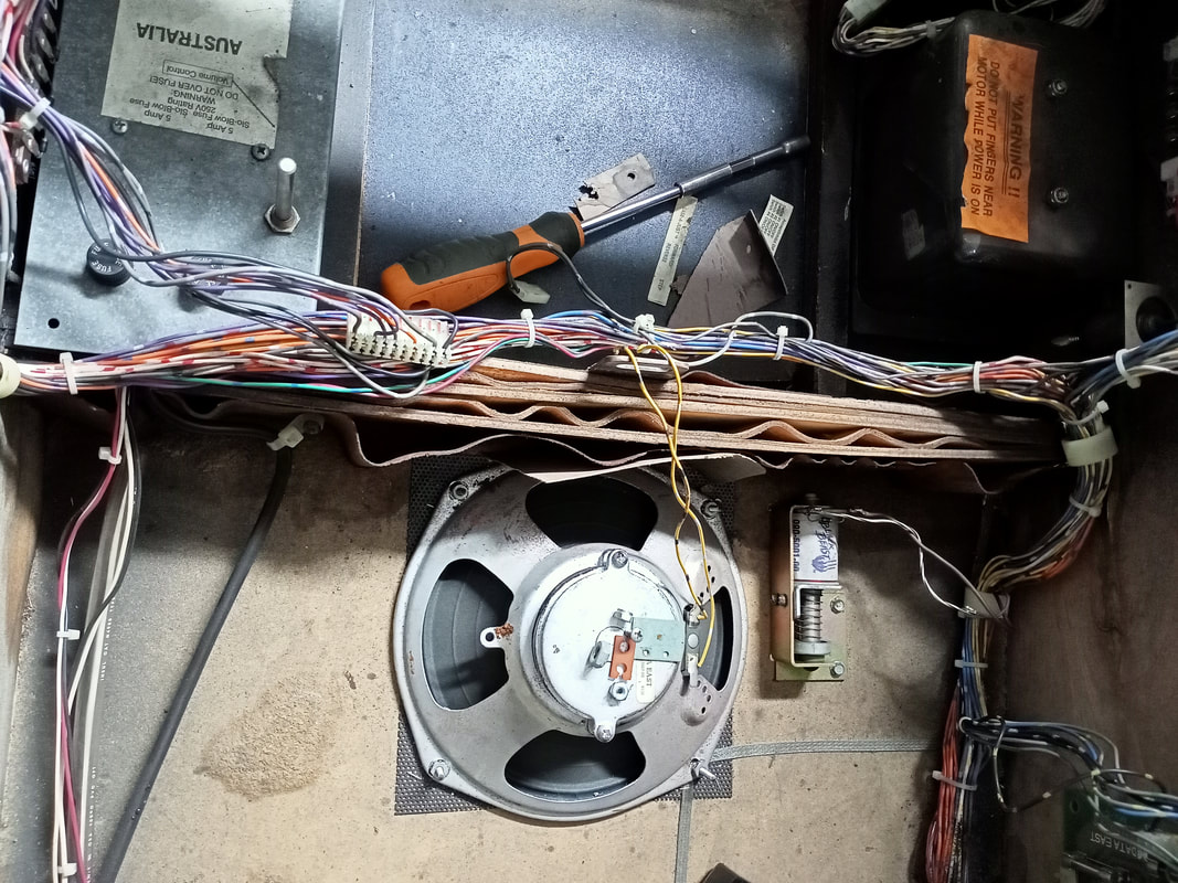
Damage to plywood within the cabinet between the speaker and coinbox.
There's nothing you can do here to "restore" timber that has been affected by water this much. It has to be ripped out and replaced. This piece was weak and was easily knocked loose, but some fragments needed some extra persuasion with a hammer and chisel. There are nails which secure this piece to the cabinet base so be aware of these when pulling it out; they're sharp! Once the piece was out, the affected area was sanded down until it was relatively smooth. You'll have to remove the speaker to do this properly. It is secured by four fin shank screws (underside) and four nuts (topside). Simply tap the shank screws out with a mallet and they can be reinstalled again if you take care to realign the fins correctly in the original holes.
Once sanding is complete, the rest of the process is the same as the cabinet underside. Apply some glue and allow to dry.
It was then time to install some new timber. Plywood is the best choice for this as it is stronger, however a piece of regular pine will do the job here. Simply cut to size and glue into place with a strong timber adhesive (Bunnings). Note that you can easily buy lengths of pine which just need to be cut to the width of the cabinet, but if you choose to use plywood, you'll have to buy a whole sheet.
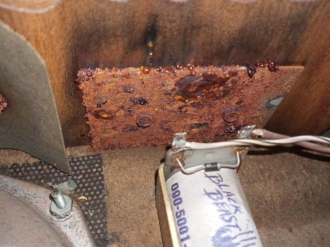
Time to move on to the metal hardware which was affected by the moisture. As the timber soaked up a lot of the water, all of the metal pieces attached to it had corroded significantly. The knocker plate was completely rusted, and the coinbox lock plate was quite rusty, too.
These are small and simple pieces of metal so if you wish you can just replace them with a sheet of metal which has been cut to the appropriate size. However, I decided to reuse the originals. Using a stripping disc (Bunnings) on the angle grinder, I cleaned the rust away until the metal was nice and shiny. Obviously this won't be worthwhile if the metal has rusted through, however in this case the rust had not penetrated the full depth of the metal. The metal was bare at this point and needed to be coated or it would continue to oxidise. I coated both pieces with some black enamel paint (Bunnings) and they turned out pretty nice. Much better than what I started with, and I like that I was able to reuse the original parts.
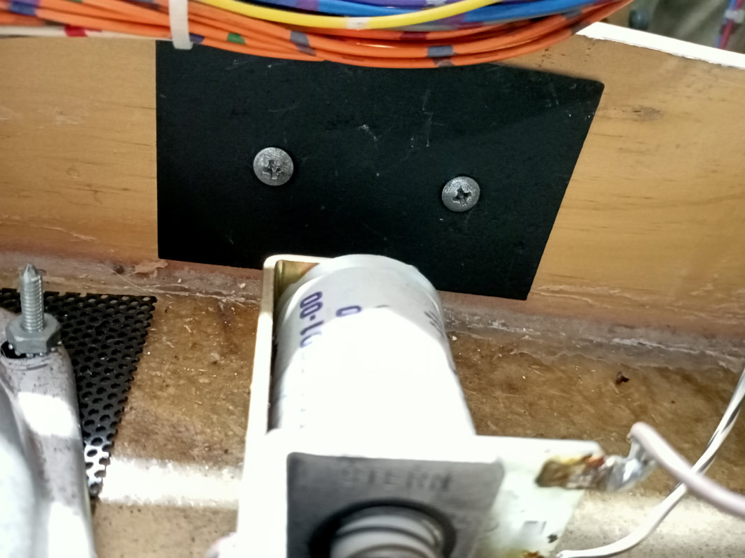
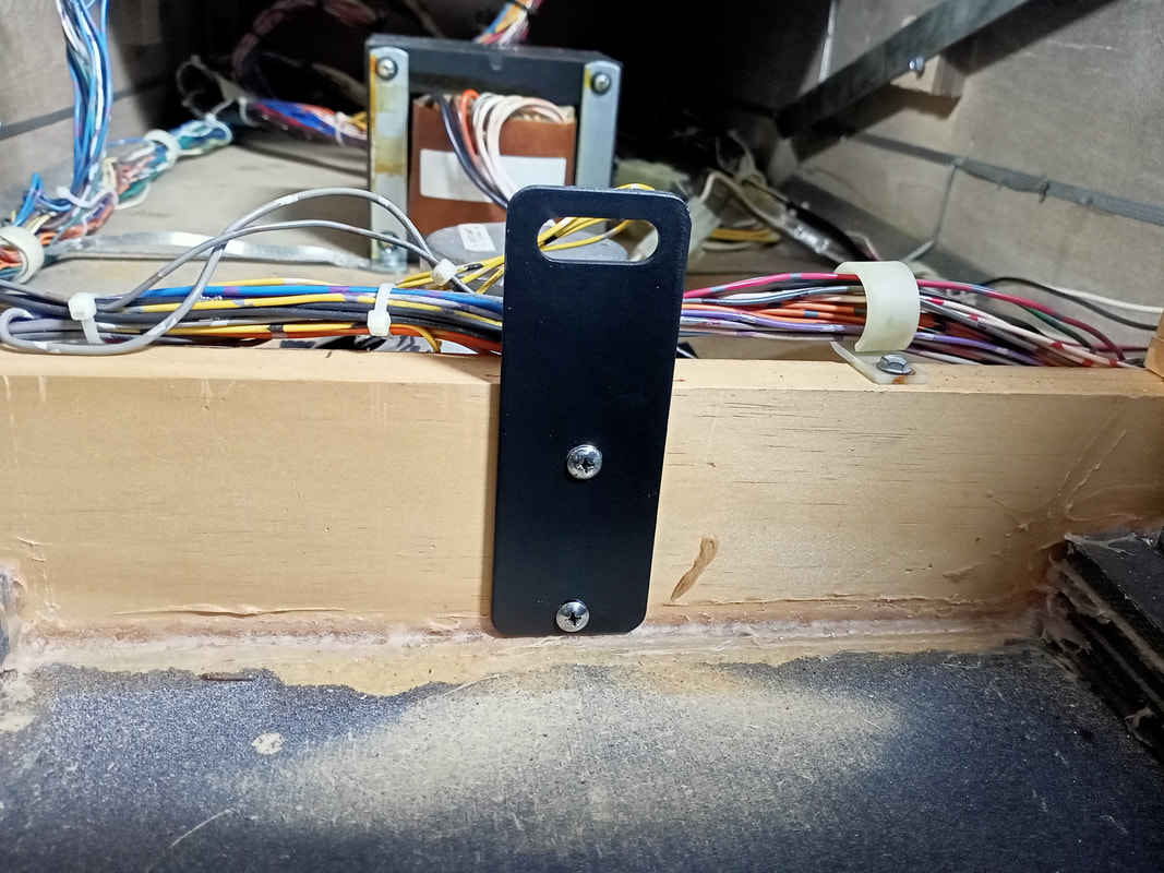
The power switch mounting plate was also looking pretty rough. Water had leaked onto it and caused the hole around the switch to rust. Luckily, I actually had a spare mounting plate in my spare parts box! So this one was a simple replacement job. 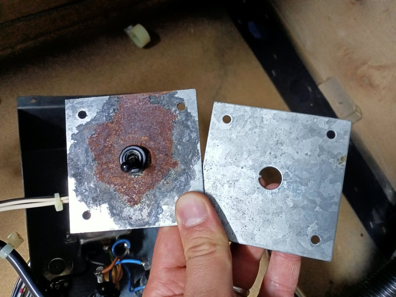
Replacement power switch mounting plate.
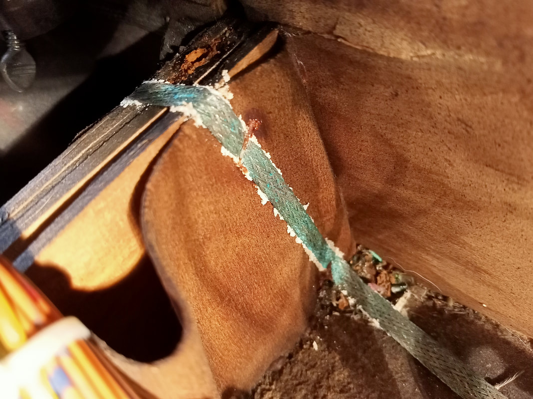
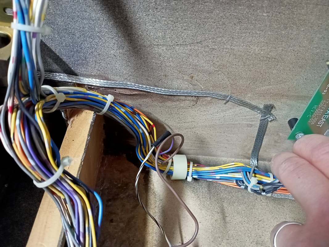
The last piece of metal which needed replacement was the ground braid. A small section of the braid which was in contact with the water affected plywood piece had started to corrode and turn green. There was no sense in cleaning this up as ground braid is easy enough to replace (RTBB, PSPA, Mr Pinball, Austral). Once I had cut the affected ground braid away and repaired the timber, I cut a new length of braid and stapled it into place, making sure it made good contact with the original braid on both sides.
Cabinet paint touch ups
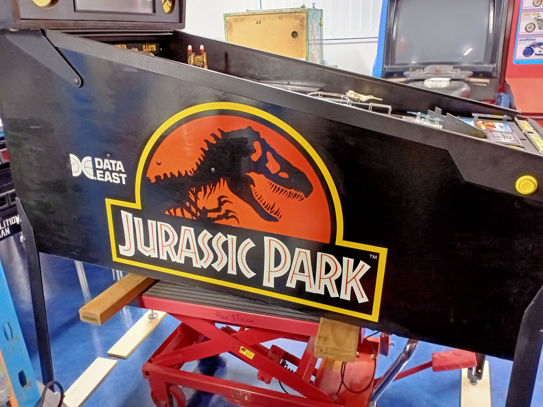
As is common on pinball cabinets this old, there were a lot of nicks, scratches and scrapes on this Jurassic Park. Luckily, Jurassic Park has to be one of the easiest cabinets to touch up, because it only uses three colours: black, red, and yellow. Pretty much all of the defects were in the black areas of the cabinet. If you want to be really precise, there is a Pinside thread which discusses which paint products match the original colours of the cabinet the closest. Apparently, Americana brand Gloss Enamel Black is the winner. You can get this paint locally, too (CraftOnline, Wildwood).
I have some generic gloss black airbrush paint which I use for pretty much all black cabinet touch-ups. I can't remember where I got it from, but black is a fairly forgiving colour so as long as the paint blends in, it doesn't really matter what brand you use. As you are covering up scratches which reveal the while undercoat, even an imperfect match will look better than nothing! At a certain angle of light you can tell where some of the larger touched-up areas are, however when looking at the cabinet from a normal standing position, you would never know. Definitely an improvement.
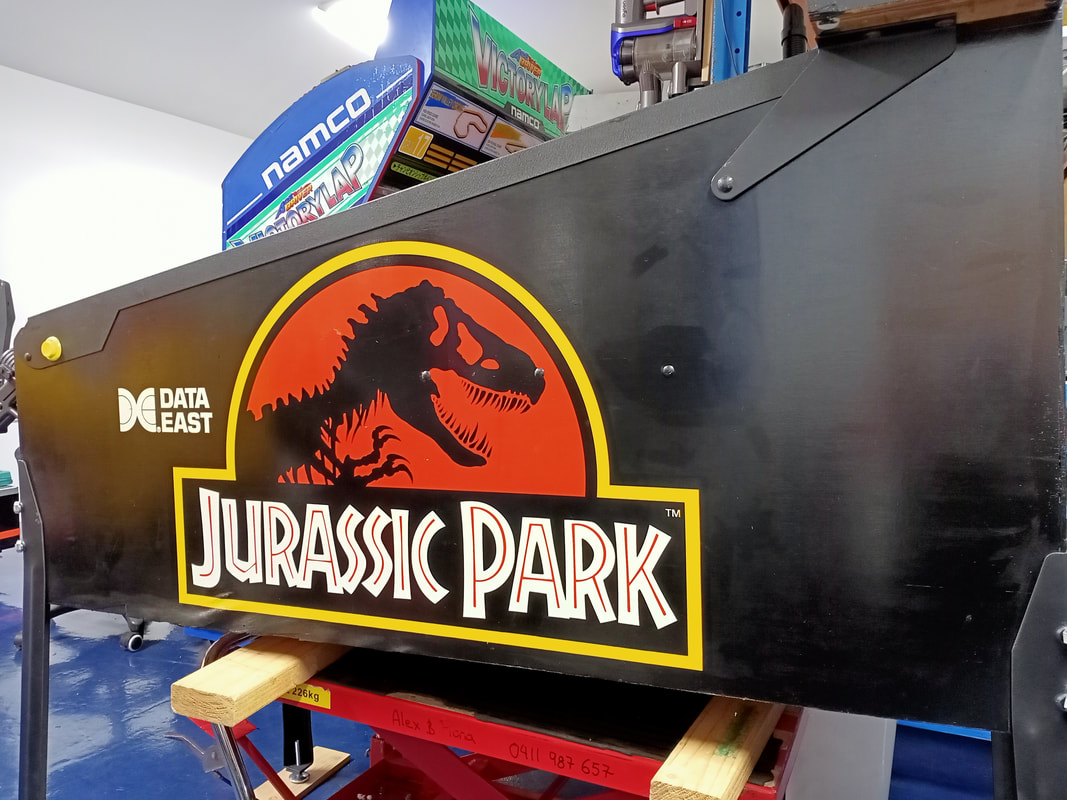
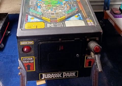
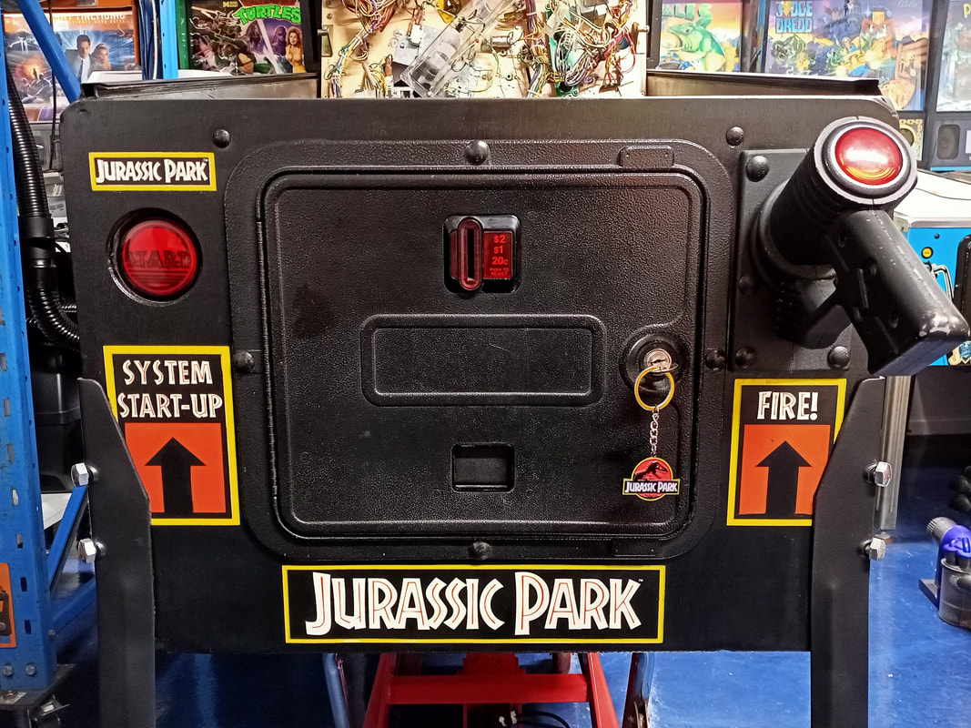
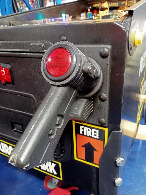
Perhaps the area where the touch-ups made the largest difference is the front of the cabinet. There was a lot of wear and flaking paint around the start button. Again, this area is all black, so it was simple enough to paint and blend it. While I was here I also repainted some minor dings on the coin door, the coin door bolts, and some parts of the gun handle assembly. Looks good!
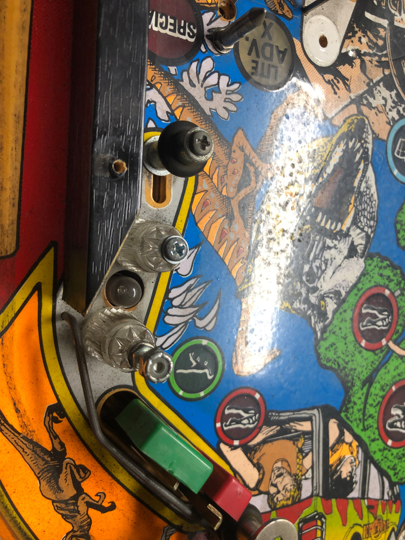
Raptor pit metal post repair
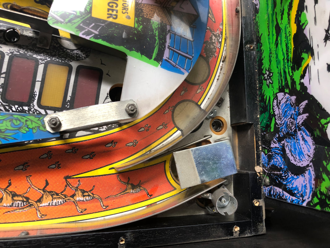
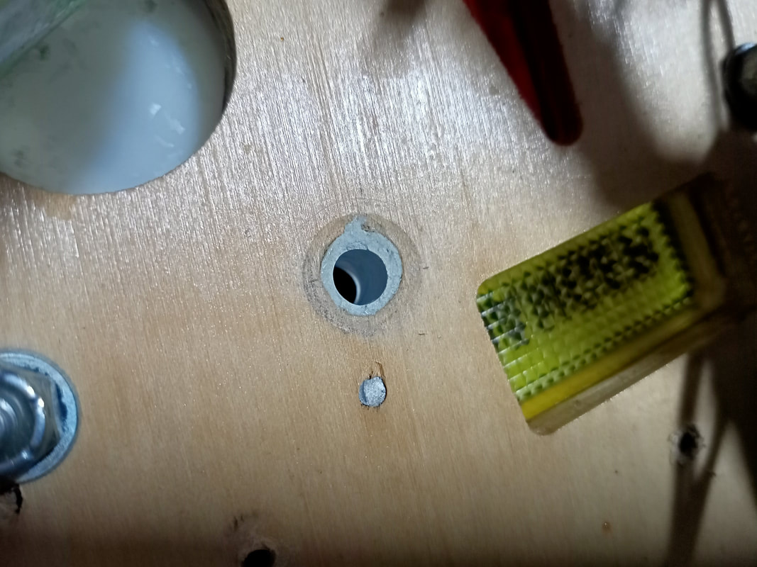
Data East games have very strong flippers, and this often results in damage to posts when they are constantly hit by high-velocity pinballs. The post holding the captive ball on the right side had broken at some point in the past, and had been replaced with a carriage bolt and nut. Not the worst makeshift repair I have seen, but the bolt was still loose in the post hole, and the rubber was not a good fit around the bolt shank. When I took the bolt out, I saw how the hole in the playfield had been blown out and stretched. This was in need of repair before a new post could be installed.
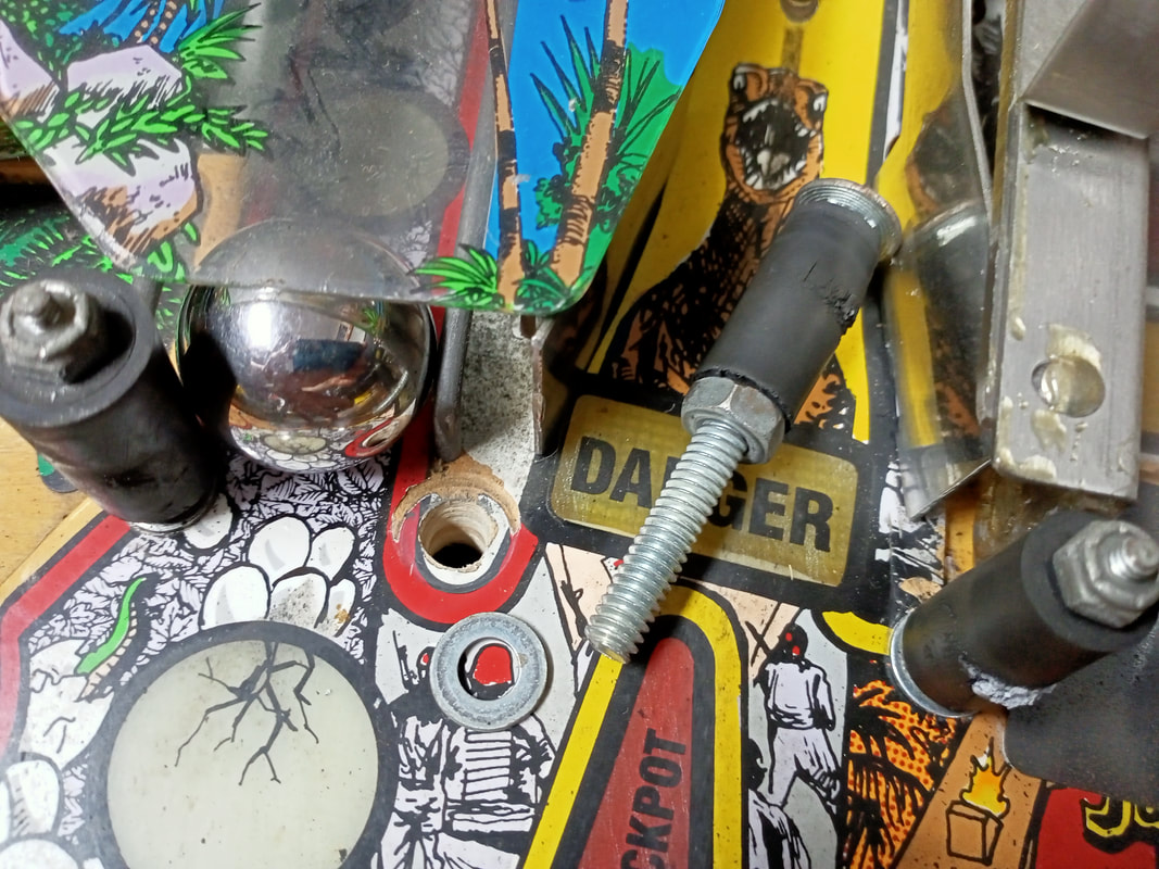
Blown post hole in the playfield by the raptor pit.
First step is to fill the hole with filler. Selley's Knead It is my tool of choice for this. Pack the hole as much as possible, leaving an excess of putty on either side. Then, using a razor blade, cut the excess from the top and bottom of the playfield. Smooth the putty over with a damp finger for a nice finish. 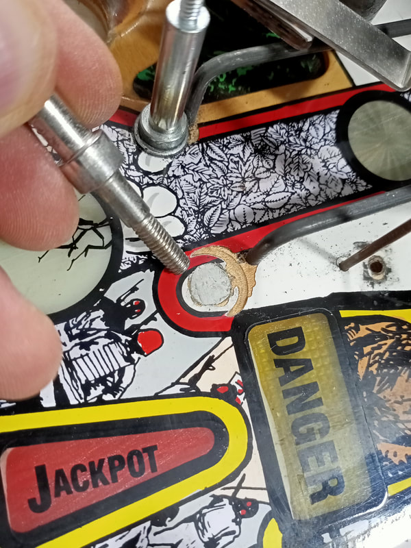
Filled post hole. Note how much wider the hole is compared to the post diameter.
Now we're ready to drill! Grab a drill bit the same size, or slightly larger, than the post you wish to install. Go straight through the putty, keeping the drill bit centred. If the putty is fully cured, it should be as solid as the timber surrounding it, and should drill out cleanly.
The posts used on Jurassic Park (part no. 530-5007-00) are the older style post. At some point in the Stern Pinball era, these posts were discontinued because they broke too easily, and were replaced with slightly thicker ones (part no. 530-5332-03, RTBB, PSPA). I actually prefer to use Williams posts instead, which are stronger still (part no. 02-4659-1, RTBB, PSPA, Mr Pinball). Regardless of which post you use, add a washer underneath the post for additional stability. The original Data East posts have a threaded shank at the top of the post. However, nothing actually attaches to these posts at the raptor pit, so the topside threads are redundant here. 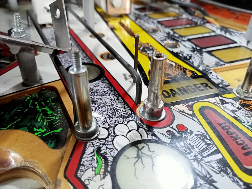
New post installed, at right.
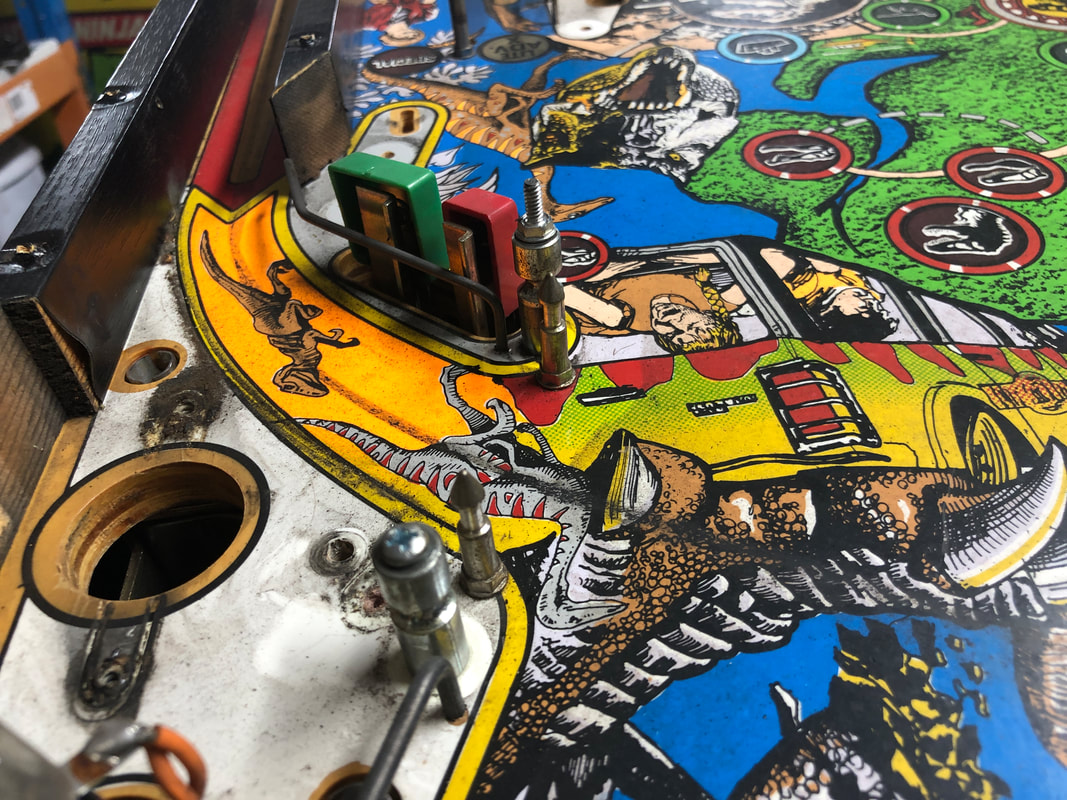
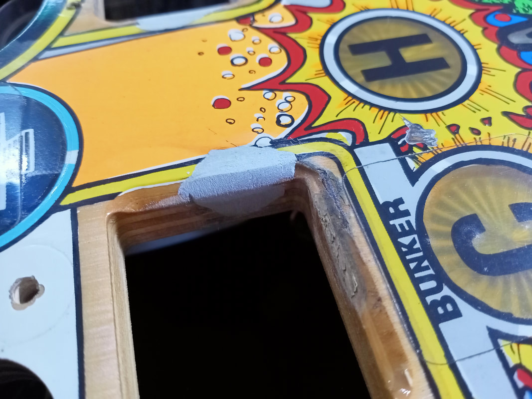
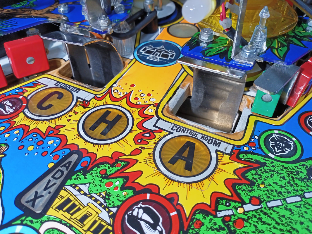
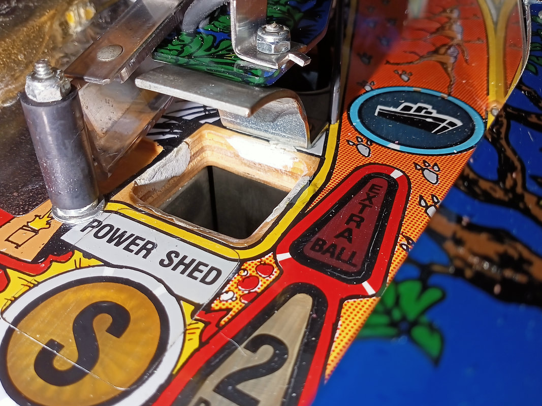
Control Room, Bunker and Power Shed scoop repairs
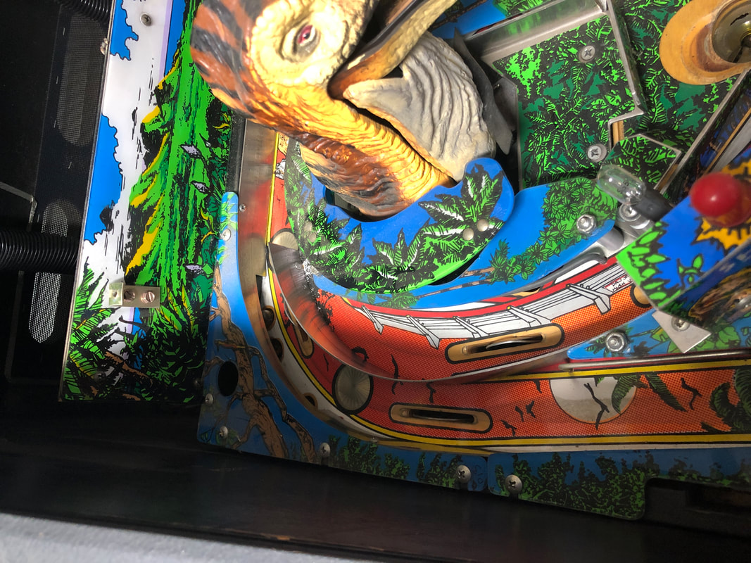
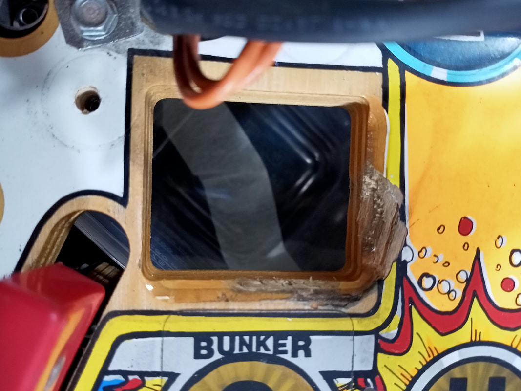
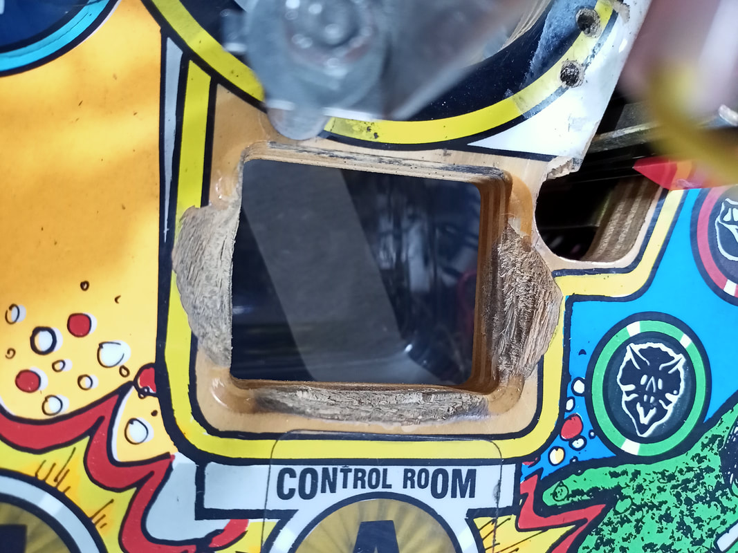
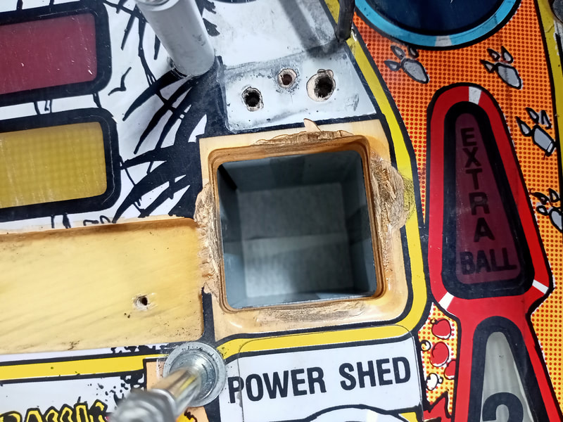
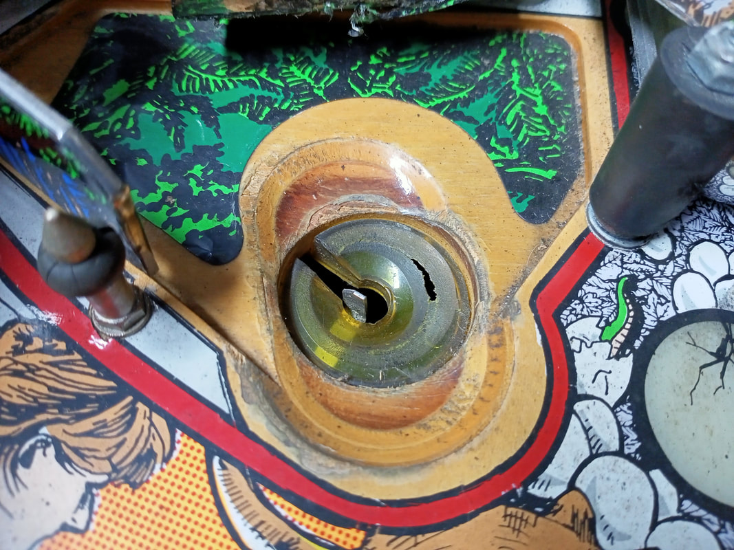
The scoop holes on Jurassic Park typically get absolutely shagged, partly because they are fairly close to the flippers which, when rebuilt, will fire the ball towards the scoops way too strongly. They also get shagged because the scoops are a major game feature, so players shoot for them a lot (particularly the Control Room and Bunker, but not so much the Power Shed). The scoop damage on this game was moderate, and in order to prepare the game for Cliffy protectors (RTBB), it needed to be patched up.
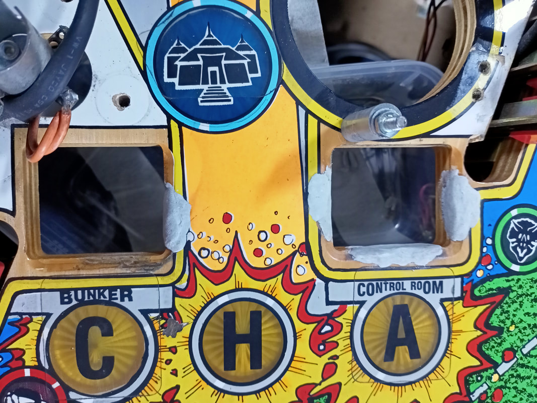
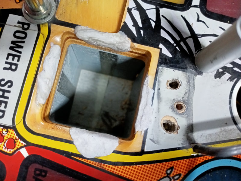
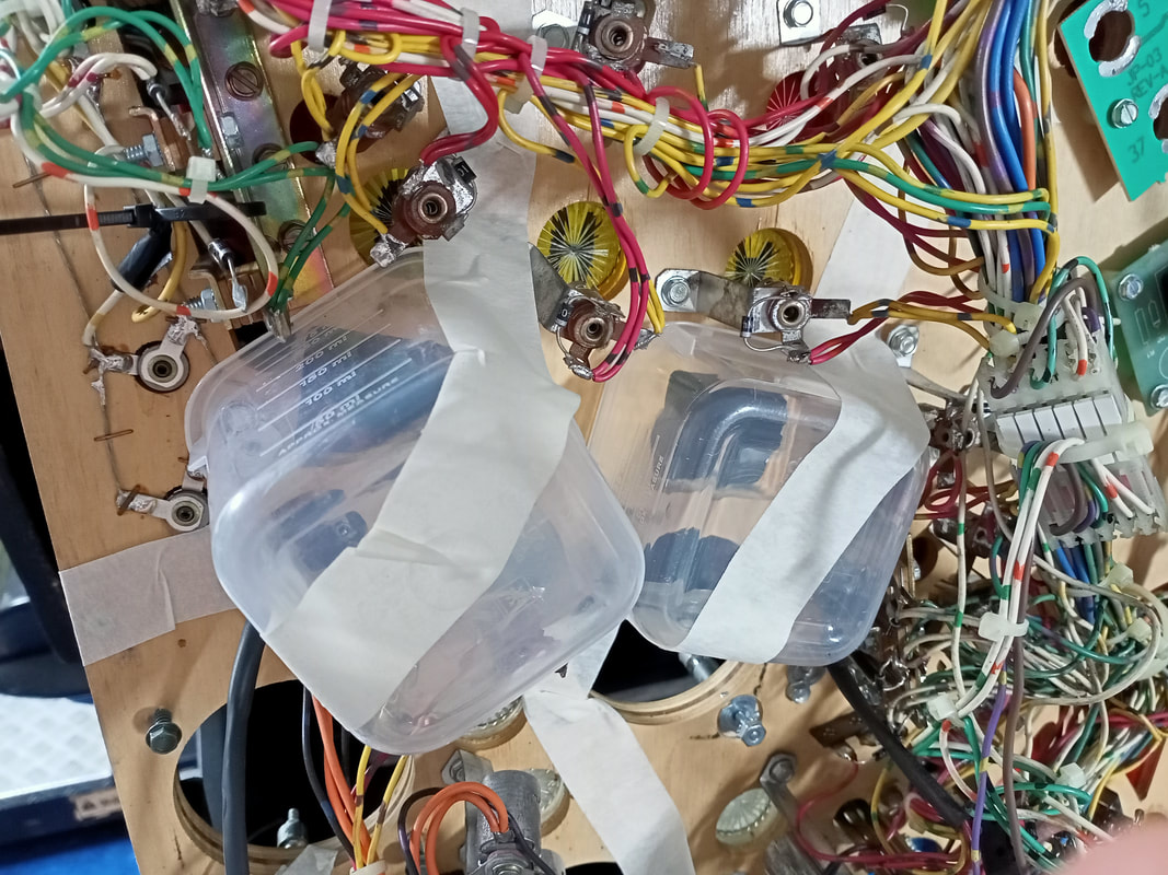
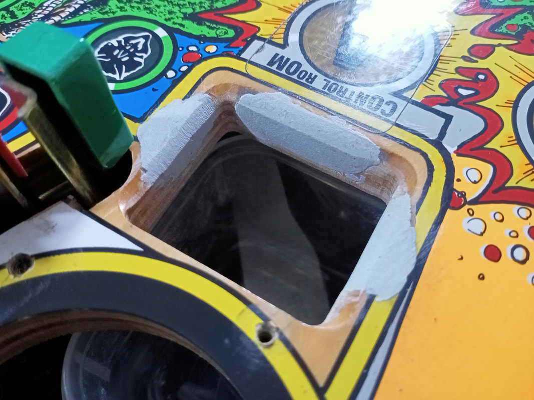
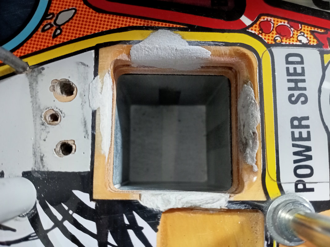
As with most timber repairs, I like to use Selley's Knead It. It is great for scoops in particular, as it adheres well to the wood and is readily malleable so it can be formed into roughly the correct shape. Remove any loose timber fibres and pack the putty into the damaged areas so it sits a little proud of the substrate. Use as little putty as possible. The Bunker was the easiest, with only one area of damage on its right edge. The Control Room was damaged on the left, right and front edges, with the damage to the left and right edges actually extending downwards to the underside of the playfield. This scoop needed the most putty of all of them to build the surface back up to its original depth. The Power Shed needed filling on all four sides. This one was a little trickier as the tiny edge between the scoop and the ramp was also destroyed, and this normally only has a tiny sliver of timber present to separate the scoop and ramp. Your best bet is to overfill this one slightly and sand it into the correct shape.
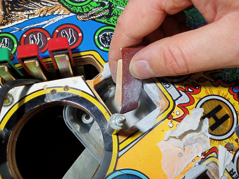
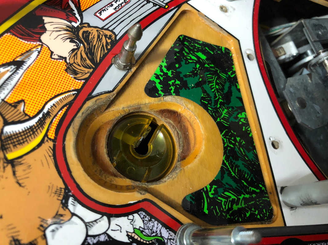
At this point I started to sand each of the scoops so that the puttied surfaces were flush with the original scoop edge. This is a frustrating task because you want to be slow so that you don't sand away too much of the surface, but if you overloaded the scoop with putty, you'll be sanding for a long time! I found that using a small piece of timber as a sanding block allows you to apply a fair bit of force to make the sandpaper more effective. Plus, it gives you a lot of control over where exactly you are sanding. I found that starting with 120 grit sandpaper quickly got me down to the level I needed to be, while 240 and finer grits were best for the final passes. Here's a pro tip: use small plastic tubs to catch the sanding debris which will fall through the scoop holes and under the playfield. It is much easier to catch the debris here rather than vacuuming or mopping it up afterwards; it gets everywhere!
I also like to match the camber of the original scoop edges by sanding the corners at a 45 degree angle to the top of the playfield. The scoops were originally formed this way to allow the ball to "fall" into the scoop when teetering on the edge. This also helps when installing Cliffy protectors as the scoops will be the same shape as they were originally, providing a better fit for the protectors.
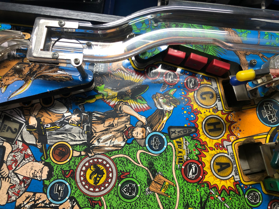
Once sanding was done, there was still one thing left to do. While I intended to put Cliffy protectors on the scoops, the pandemic was causing huge delays in getting orders from Cliffy in the US, and he was backlogged for months. I had to do something in the meantime, as the owner didn't deserve to have their game held from them for an indeterminate amount of time until the protectors came back into stock. So, I decided to touch-up the worn areas of the playfield at the scoops, with the view that the protectors would eventually cover most of these areas anyway. Based on the images of the installed protectors on Cliffy's website, only one area of repair would be showing even after the protectors were installed. That is the area on the right edge of the Control Room scoop. The repaired areas on the Bunker and Control Room scoops would be completely covered up by the protectors, but as they required the same touch-up colours as the Control Room scoop, it was easy enough to do them all at the same time. Surprisingly we didn't even need to mix any colours. The damaged areas were quite small, so a small brush was all that was needed for application. The yellows were a great match with Wicked W003 Yellow, and the black key lines were done with Wicked W031 Jet Black. One small area below the Bunker scoop was also touched-up, which was part of the red "explosions" around the round C and H inserts. This was done with Wicked W015 Crimson. Finally, the paint was protected with a thin layer of clear gloss nail polish. This is to give the paint a small protective layer until the protectors arrive to cover the area.
This was by no means meant to be a permanent, professional repair. It was purely to disguise the touched-up areas a little until such time the protectors will cover them up. Standup targets not registering
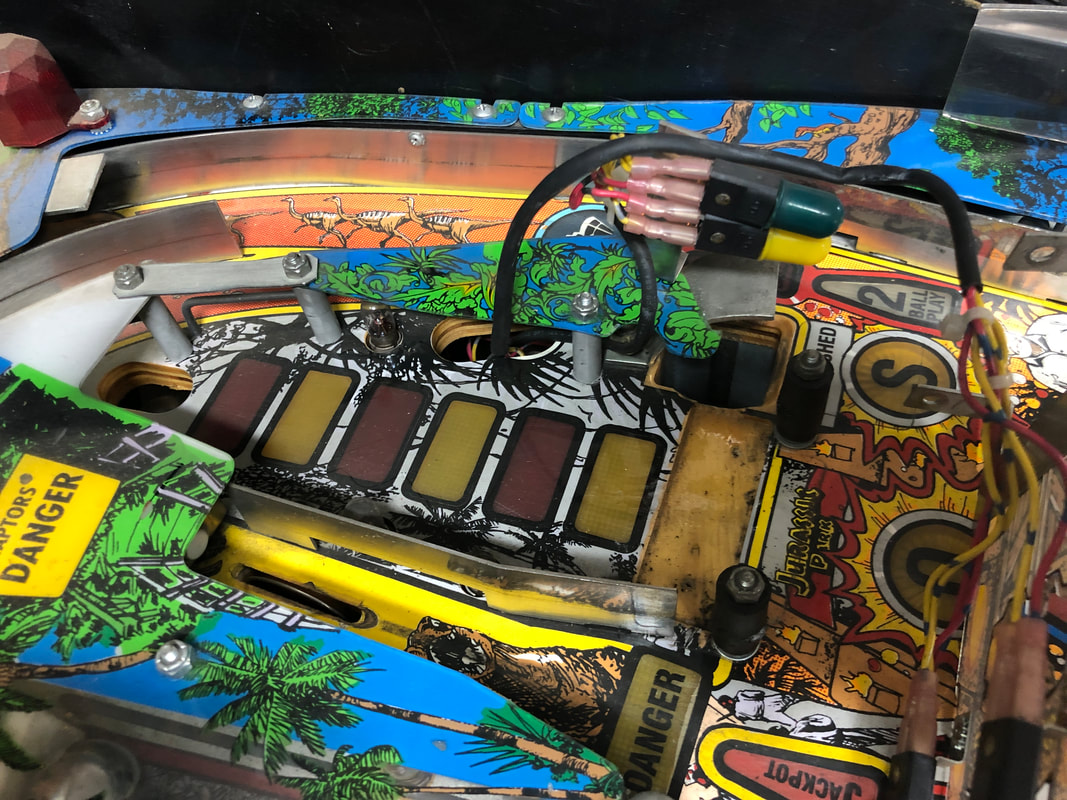
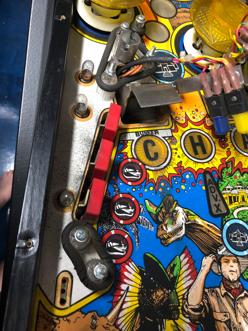
The faces of the standup targets are moulded around the left, right, and top of the target to enclose all of the leaf switches in the space behind. This looks nice, but causes issues where multiple switches are placed close together. For example, the three adjacent targets next to the right pop bumper (Herrerasaurus low, Herrerasaurus top, and Brachiosaurus low). The target faces could not be depressed enough to actually activate the switch.
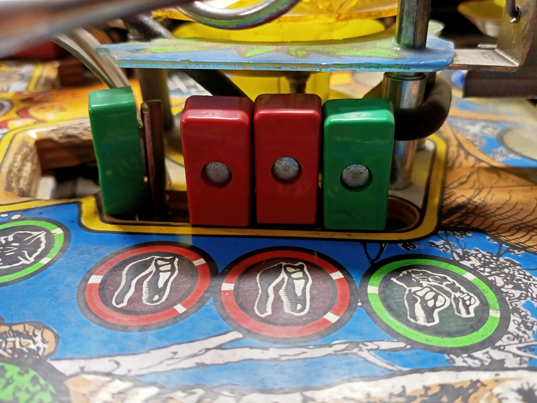
Non-working standup targets.
The switch assembly is held in place by two woodscrews. Remove them and pull the assembly out. You may find it easier to push on the target faces from the topside of the playfield so they slide out smoothly. There are a couple of lamp sockets which get in the way of pulling this assembly out of the playfield, so it is easier to detach these first. Once the switches were out I could see that they were all crowding around the centre switch, and the outer two switches were angled inwards. This meant that the plastic target face struck the switch backing plate and stopped moving towards the leaf switch. This prevented the switch from closing. 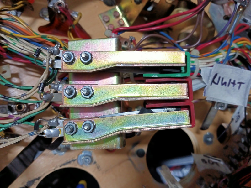
Rear side of non-working switches. Note crowding and inward-facing brackets.
While you are here, be sure to check the backing material on the switch brackets. This often degrades and causes chunks of rubber and foam to get stuck in the switch leaves. Remove the old stuff and replace with new. I use some rubber with an adhesive backing (easy to get from Clark Rubber) or weather strip/window seal material (Bunnings). 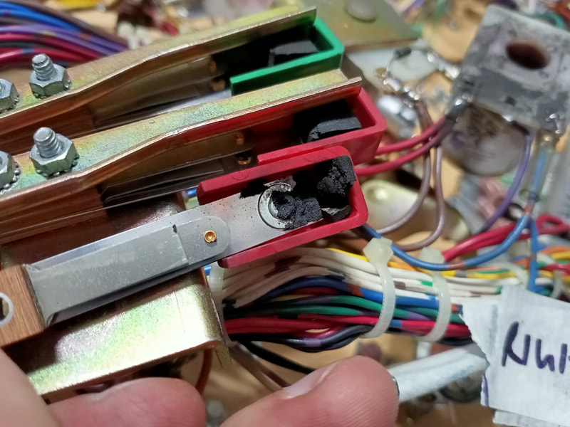
Degraded rubber pad on rear of target face.
The switches are easy to adjust. Simply loosen the two metal screws holding them to the assembly and realign so they are straight. Push hard on the target face to make sure it depresses cleanly and activates the switch. 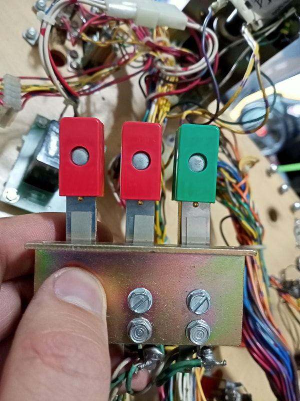
Straightened and adjusted switches.
Of course, fiddling around when installing the switcth assembly caused a wire to fall off an adjacent switch - the Triceratops target (white-yellow). Once that was resoldered, all of the switches worked normally again. 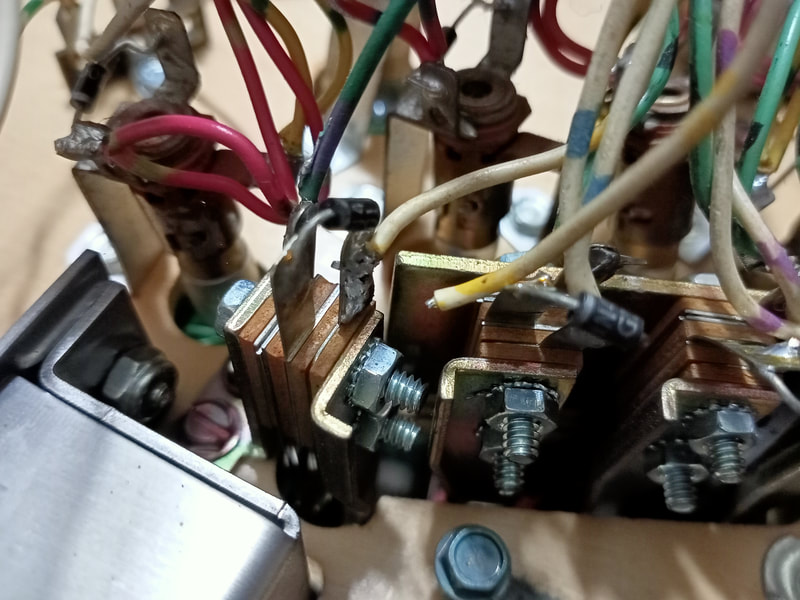
Wire broken off triceratops target.
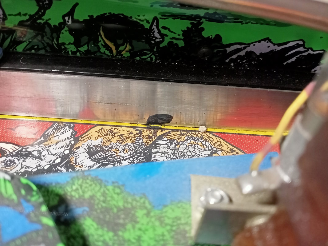
Liquefied rubber all over playfield
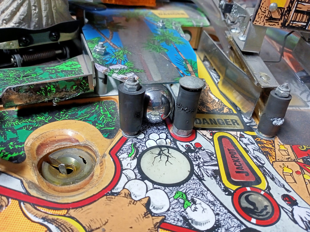
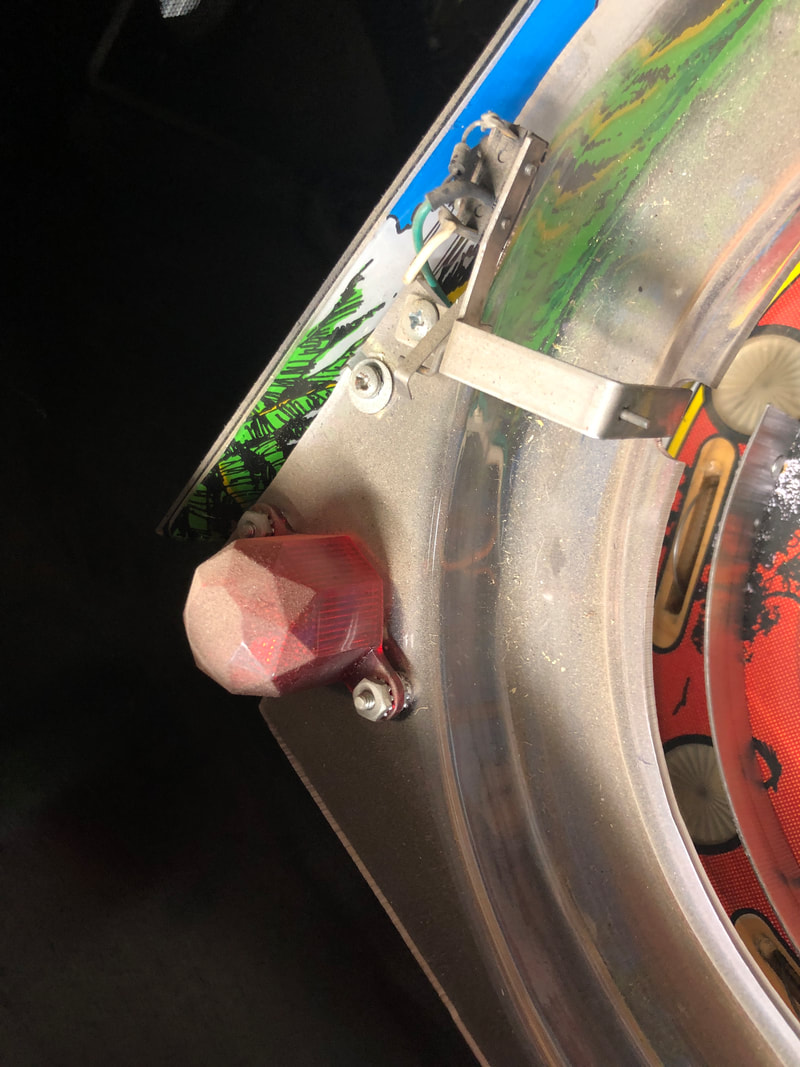
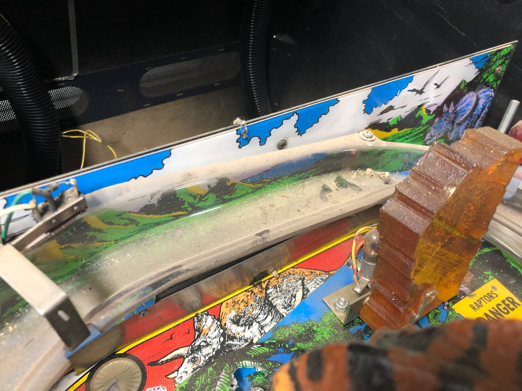
Data East used a rubber grommet on top of the apron to give the playfield glass some extra support when leaned on. For some reason, the type of rubber used for this grommet tends to degrade and melt over time, turning into a black, viscous fluid which drips all over everything.
Liquified rubber grommet leaking onto the apron and playfield.
This game spent some time upended on its rear, which allowed the liquified rubber to drip vertically down the playfield. In fact, residues of the rubber were at the very back of the orbit lane, and had actually seeped behind the ball guide against the playfield backboard.
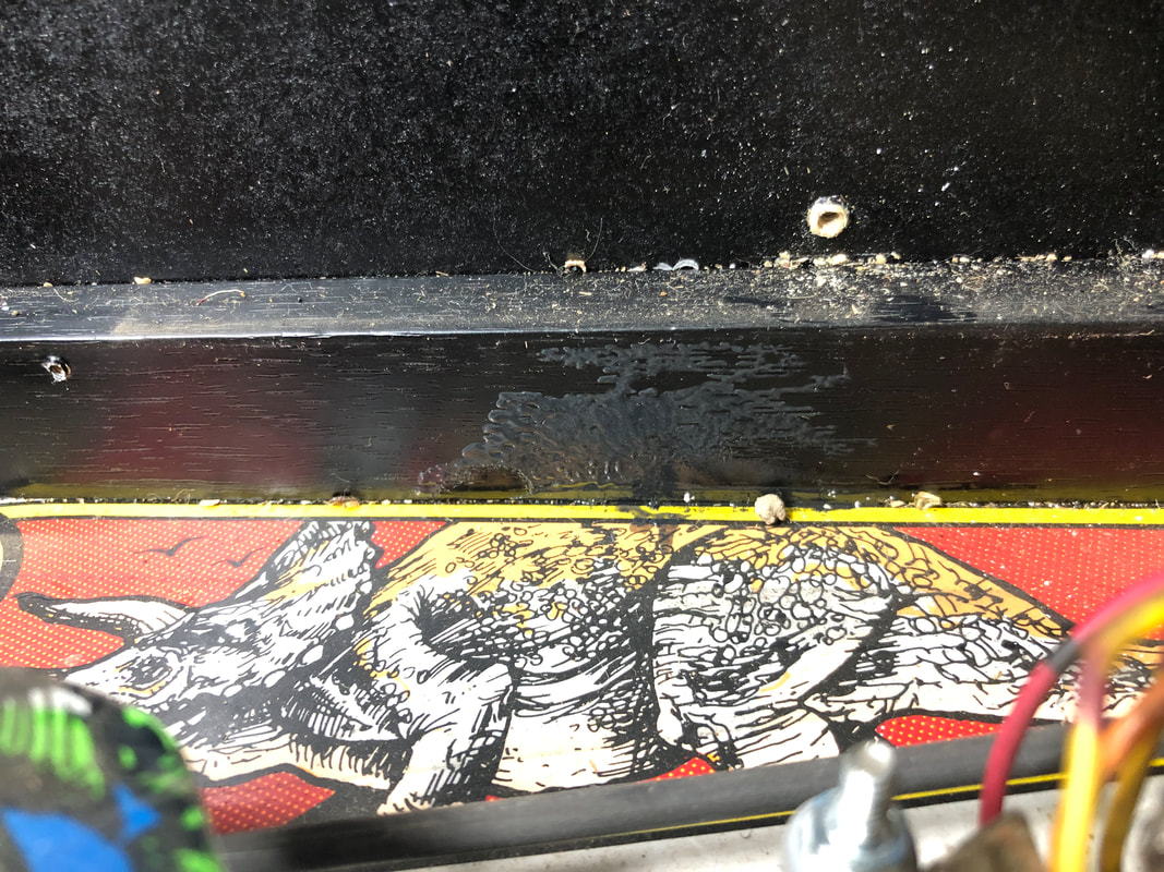
The residue is very sticky and messy, but cleans up easily with some alcohol. There is no replacement part available for this grommet. However, a square piece of rubber can simply be cut to size or another grommet can be repurposed. Unless there are going to be heavy weights on the playfield glass above the apron, it isn't a particularly important part to have, anyway. 
Original location of the rubber grommet, after cleaning.
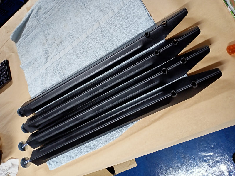
Leg and lockdown bar refurbishment
Whenever I get a machine in for service, I always make an effort to clean and refurbish the legs. It does wonders to the look of the machine, and you can clean old legs up to look basically brand new. At over $150 (PSPA, Mr Pinball) for a full set of legs, it's worth giving it a go...
...sometimes. All of the legs on this game were a little worn and in need of a freshen up. One of them, however, had the leg leveller rusted in place, and it simply would not budge. In fact I ended up tearing the "foot" off the leveller while trying to move it. 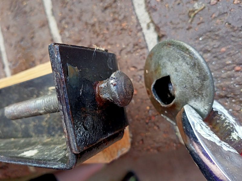
What it looks like inside a leg leveller!
Next, I sprayed the bejesus out of it with WD-40, and then cut a notch into the head of the bolt so I could use my impact driver to unscrew it. No such luck. All I got out of it was two broken impact driver bits. When that failed, I cut sections off each side of the bolt head and used a spanner to try and undo it. That didn't work either, even when I used a mallet to "persuade" the spanner. 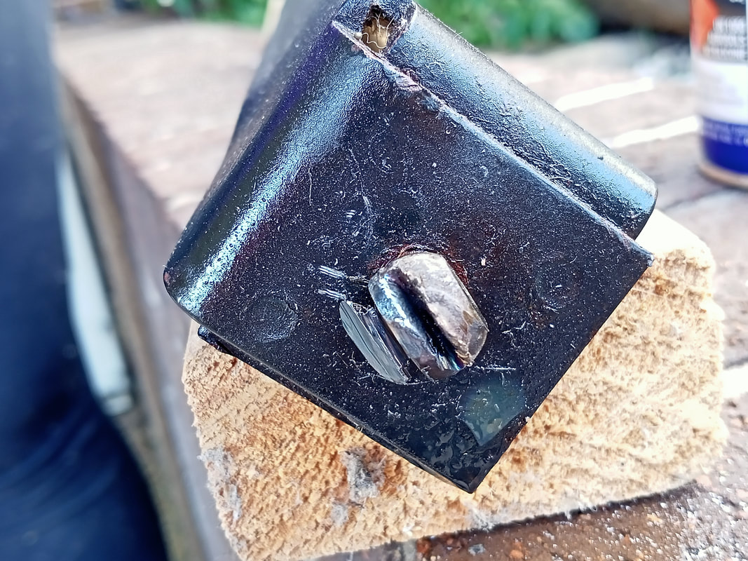
Cutting notches into the leg bolt to remove it with a driver or spanner.
I even tried soaking the base of the leg in a rust removal solution overnight. It had no effect at all. The rust had locked the leveller completely in place - permanently. The last resort you can use in these situations is a drill. Cut the head of the bolt off with an angle grinder, and use a drill bit slightly narrower in diameter than the bolt. For reference, leg levellers use 3/8" bolts. Drill straight through the bolt, taking care not to touch the thread on the leg. With a nice hole in the centre of the bolt shank, the remaining material locked in the threads may be pulled out. I wasn't so lucky in this case because the rust had caused the bolt to fuse completely with the leg thread. I ended up using a 3/8" drill bit to fully remove the remains of the bolt, as well as some of the original thread material. Unfortunately when a bolt is this badly melded to the thread, damaging the thread is sometimes unavoidable. 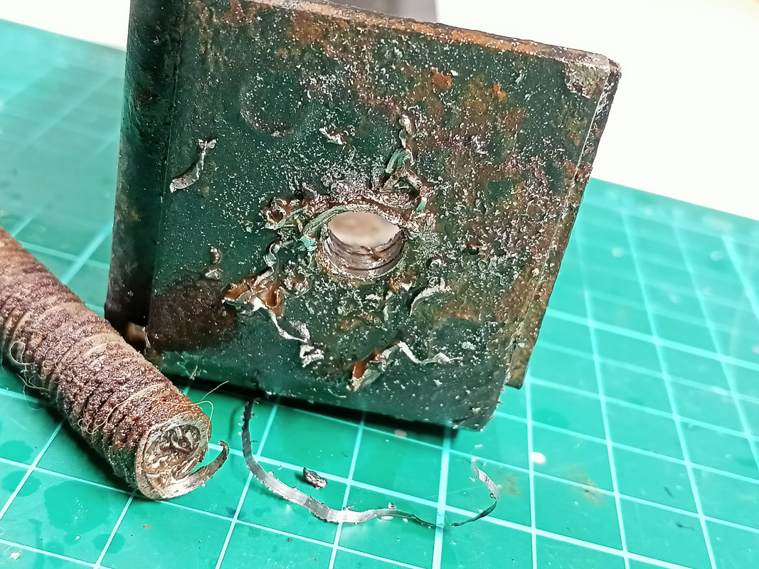
Using a drill to drill through the seized bolt finally broke it free from the leg.
However, that doesn't mean the leg is ruined. I used a stripping wheel on an angle grinder to remove burrs and the remains of the old bolt from the bottom of the leg. This also removed a lot of the rust which had accumulated on the bottom edge of the leg. 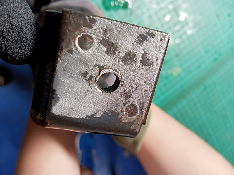
Base of the leg after stripping and cleaning.
However, there was still the problem of fragments of the bolt remaining within the bolt hole, stuck to the threads. For this, I used a 3/8" tap and die to ream a new thread for the leg leveller. The tap found the original leg thread, and as it was screwed deeper into the leg, it cut out the old bolt fragments which were stuck in those threads. So I was not actually cutting a new bolt hole, I was just freeing up the original thread. Obviously, every time you use a tap in this fashion, destroying or enlarging some of the original thread is unavoidable. However, the final result was quite good, and a new leg leveller could be screwed into the hole easily. It did wobble a very slight amount due to the slightly enlarged threads, but this can be easily fixed by using a retaining nut on the leg leveller thread below the base of the leg. 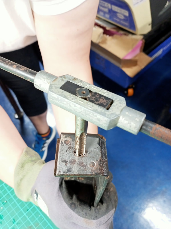
Using a tap and die to cut bolt fragments out of the leg thread.
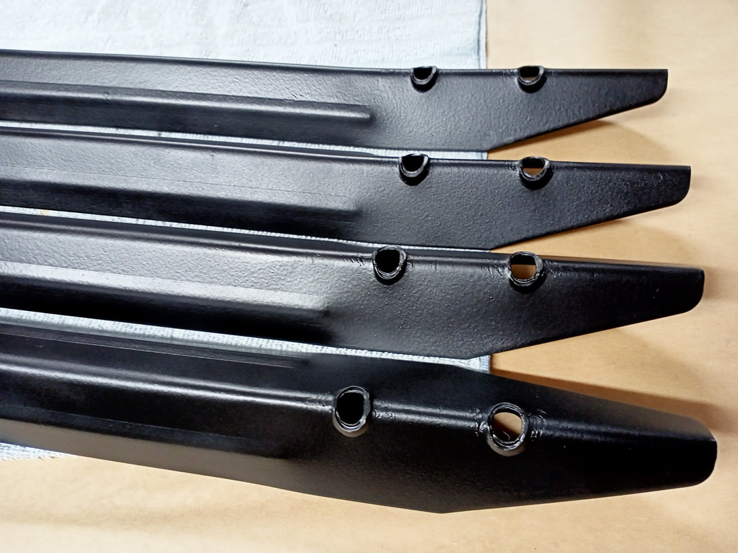
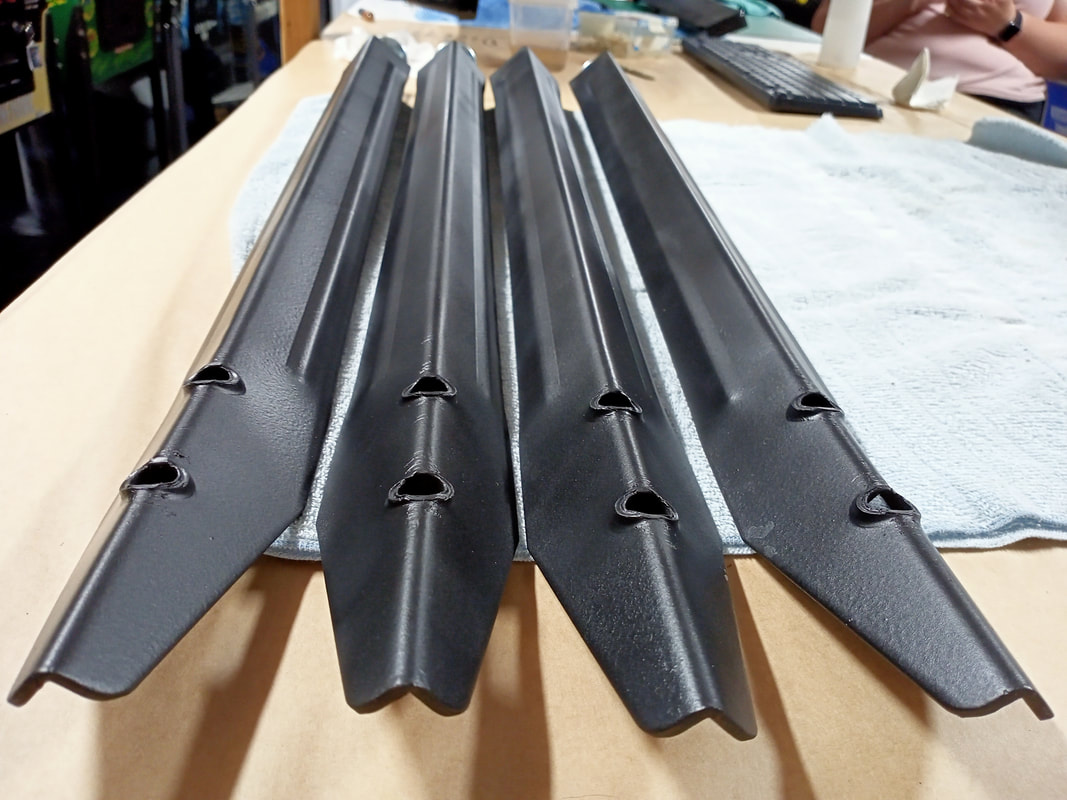
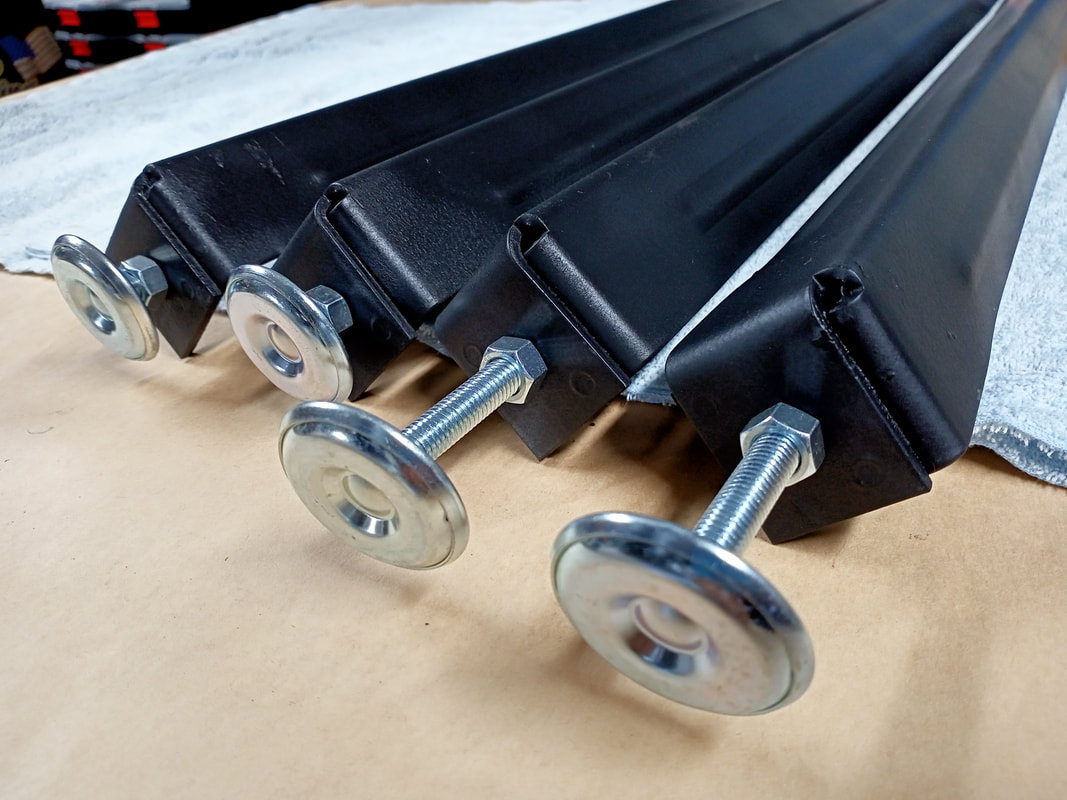
The final step was to repaint and recoat the legs in their entirety. I cleaned all of the legs in detergent and let them dry fully. Then, I painted them all with Metalshield Epoxy Enamel (Bunnings). This paint is a good match for the original black powder coat finish. If you want, you can leave it at that, but I like to protect the paint with an additional layer of clear coat. For this I used Dulux duramax semi gloss (Bunnings). This gave the legs a bit of a shiny look which I think looks really nice. If you want to do it all in one hit, you can use a satin/semi gloss black paint instead of a flat black and clear. Once the paint was all dry, four new leg levellers were installed (Mr Pinball, RTBB, PSPA). At this point the legs were basically good as new!
The lockdown bar got the same treatment as the legs. There were some spots of rust and areas where the original paint had flaked off. The corners where people normally rest their palms were the worst affected. The same paints as used for the legs were sprayed on the lockdown bar which make it look a lot nicer. 
Lockdown bar after new paint application.
Coin door refurbishment
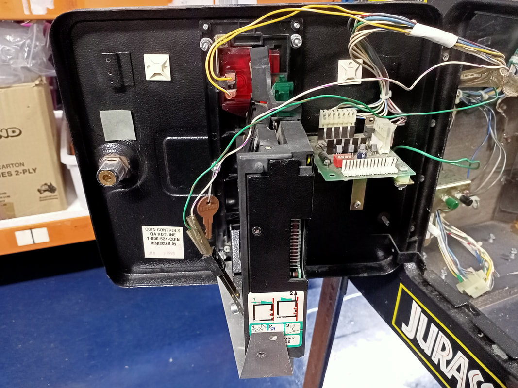
Coin doors always get messed around with, and this one had a few small issues to address. The first issue was the slam tilt switch. This is normally mounted to the coin door, but for some reason it had been moved and taped to the interior left wall of the cabinet. No idea why.
Slam tilt switch moved to the interior left wall of the cabinet.
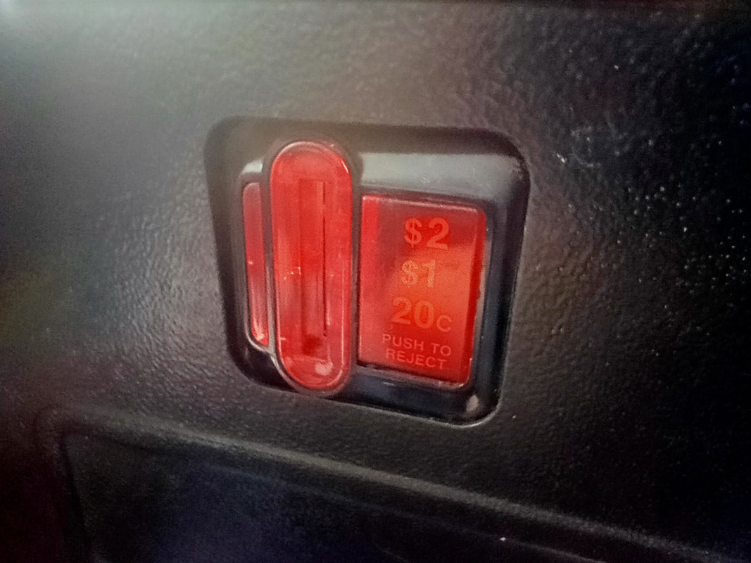
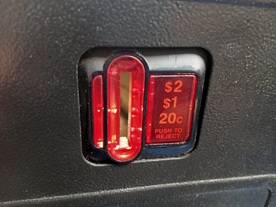
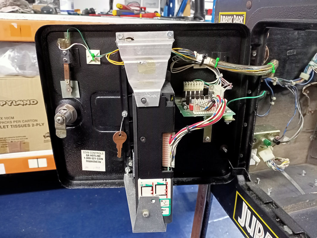
The coin slots were also looking a bit crappy. The top edge of the bezel which the coin slot/faceplate sits in was sitting too far back, causing the faceplate to appear "sunken". This turned out to be due to a missing nut on the rear of the coin mechanism bracket which allowed the faceplate to move backwards. 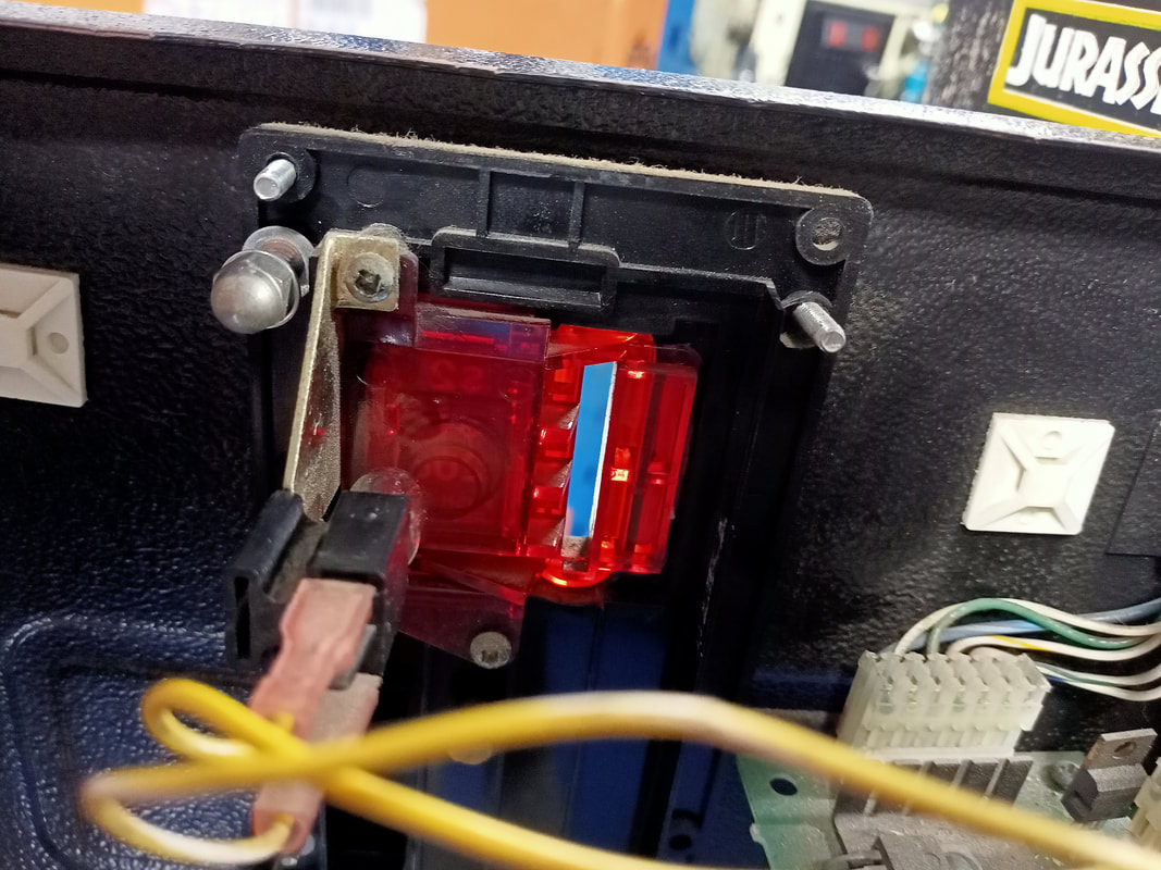
Missing nut on the right side of the coin mechanism bracket.
While it may not look like it, there was a noticeable difference to the look of the coin slot and it did not appear to be sunken into the coin door after a new nut was installed. The bezel does not sit flush with the coin door though, so you can never bring it forward to stick out of the coin door completely.
Of course, the coin door lock also had to be drilled out because the owners had lost their keys. A new coin door lock was installed. All that was needed after that was to clean the wiring loom and route it properly though the mounting points on the rear of the door.
Flipper repairs
The flippers were weak and sloppy from not having been serviced in decades. But apart from that, there was one big problem with the end-of-stroke (EOS) switches on these flippers. The wires to the EOS had been cut on both sides, and the wires to each switch had simply been twisted together to ensure the EOS were always "closed". The wires originally connected to the switches were hanging loose in the cabinet. No electrical tape or anything else to protect from shorts. Not good!
There tends to be some confusion surrounding Data East and EOS switches. Jurassic Park was actually the first Data East game to employ an EOS system. The theory of operation of the system is explained in Service Bulletin 49. The EOS switches tell the game that the flippers are in the engaged position. However, they have no impact on the "power" or "hold" voltages sent to the flipper coils. The flippers will always energise with a full power stroke powered driven by 50 volts, and then revert to a "hold" voltage of 9 volts after ~40 milliseconds. This is controlled by the CPU and occurs whenever a flipper button is pressed; it has nothing to do with the EOS. The sole reason for implementing EOS was because the Raptor Pit kickback fires balls back at the flipper with such force that the 9 volts which holds the flipper in the up position may be overpowered, causing the flipper to drop. In this case the EOS will close, but the flipper button is still depressed, so the CPU knows that the flipper bat has fallen when it should not have. The game then sends 50 volts back to that flipper coil to keep the flipper raised. It's a neat system, and Data East continued to use it even on games that had no kickbacks that fired the ball back at the flippers. However, it creates a weakness in that the EOS must be working perfectly in order for the flippers to work. If the EOS switch blades are tarnished or damaged such that they do not make good contact, the flippers will be very weak. This problem is discussed on Pinwiki as well as in Clay's repair guides. The best solution? Just replace the EOS switches (part no. 180-5124-01, PSPA, RTBB). Note that Jurassic Park originally had older style EOS switches which had a habit of cracking. The part number mentioned above is for the new style switch, which was used into the Sega Pinball era. More information on the change is in Service Bulletin 54. If you are trying to repair some slightly used switches, make sure the switch contacts are clean and shiny. You can clean them by "sanding" them with some paper or cardboard; but stay away from anything abrasive like a file or sandpaper! After installing three flipper rebuild kits which included new EOS switches (RTBB, PSPA), all of the flippers returned to being nice and strong, like they should be. 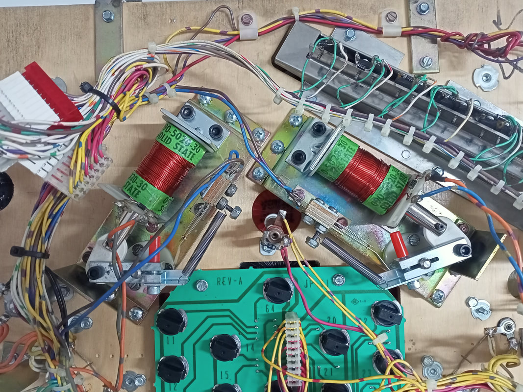
Flippers after repair and refurbishment. EOS switches connected.
Power cord replacement
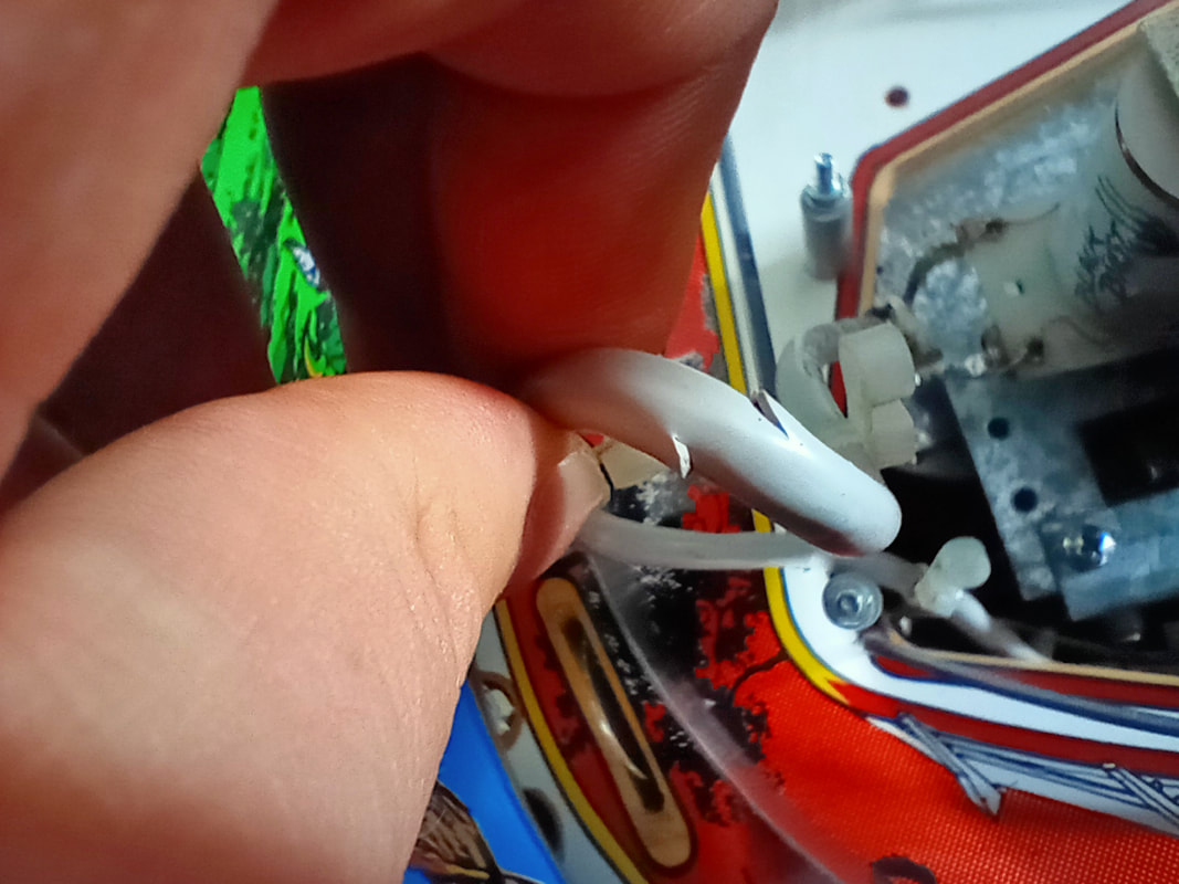
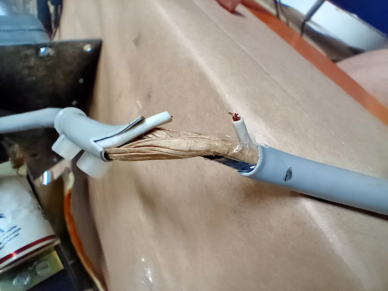
As is typical for most game power cords, this one exhibited some damage. The outer insulation had been ripped away, exposing the neutral wire within. There was no damage to the neutral wire's insulation, so everything was intact electrically. However from a safety perspective it's always best to replace the entire cord. You can grab any extension cord and cut the female plug off to use as a replacement. I grabbed a new one from Jaycar as they were the only place that sold black cords in reasonable lengths. Make sure you have enough length to snake it through the cabinet and to the socket outlet! I find a 5-metre cord length is perfect.
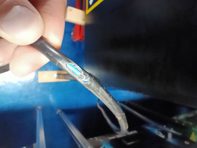
Damaged power cord.
Take note of the power cord wiring before you disconnect the old cord. Active and neutral are wired to fuses, while earth goes directly to the line filter. Simply cut the old cord, strip the conductors on the new one, tin them, and resolder. 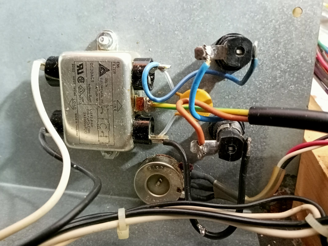
Power cord connections within the power module.
Sound board repairs
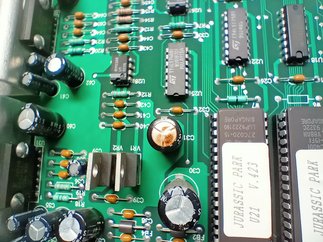
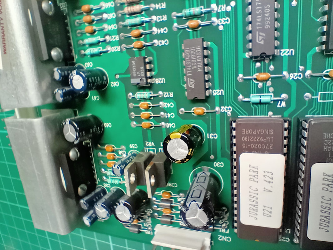
This was a relatively simple one. There did not appear to be any issues with the speakers or sounds, however visual inspection of the sound board showed that capacitor C31 (470uF, 25V) was about to shit itself, with residues on top of the vent and a bulge starting to form. It got replaced as a precaution (Jaycar).
MPU board repairs
The MPU board needed a little work, primarily around the battery area. The batteries had leaked, so it was time to replace the entire battery pack with another energy storage solution.
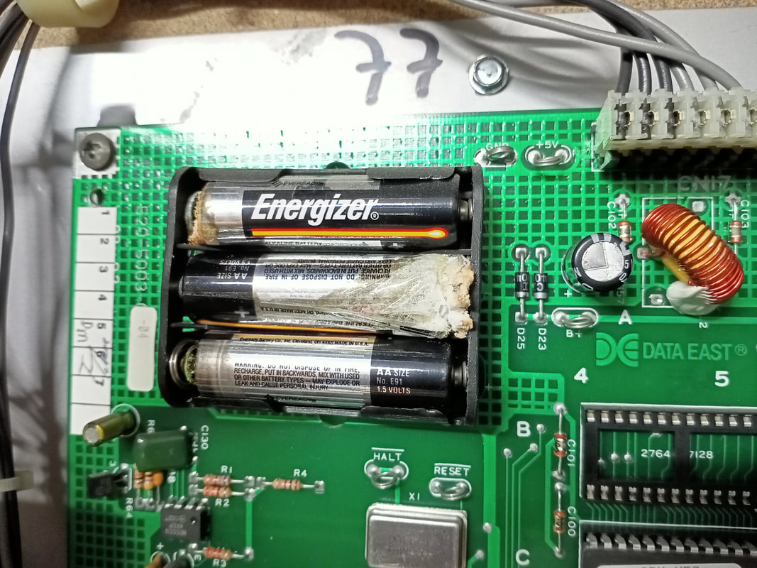
Original leaking batteries mounted to the board.
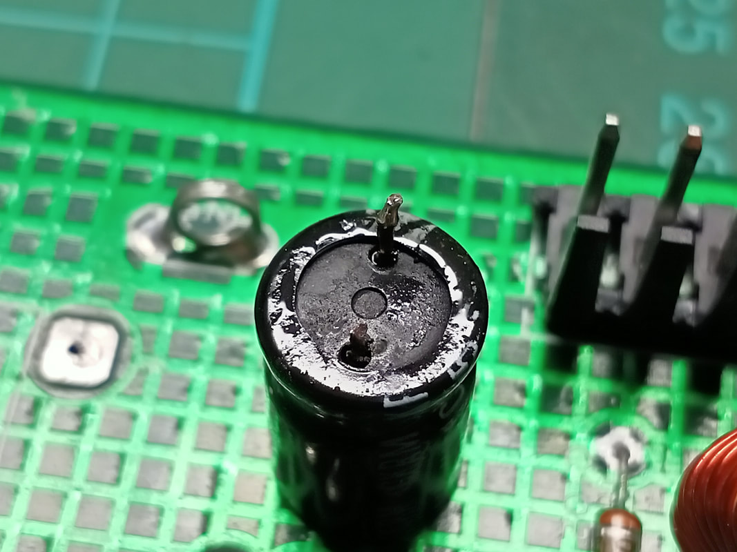
After cutting off the battery pack with side cutters, I took a closer look at surrounding components. The capacitor at C157 (470uF, 25V) had some residue on top of it, which made me suspect it was starting to leak. I decided to replace it as a precaution (Jaycar), and when I cut it from the board I smelled the electrolyte which had started to leak out of the bottom of the capacitor. Good thing I decided to replace it! I could repair this area of the board at the same time I dealt with the battery leakage.
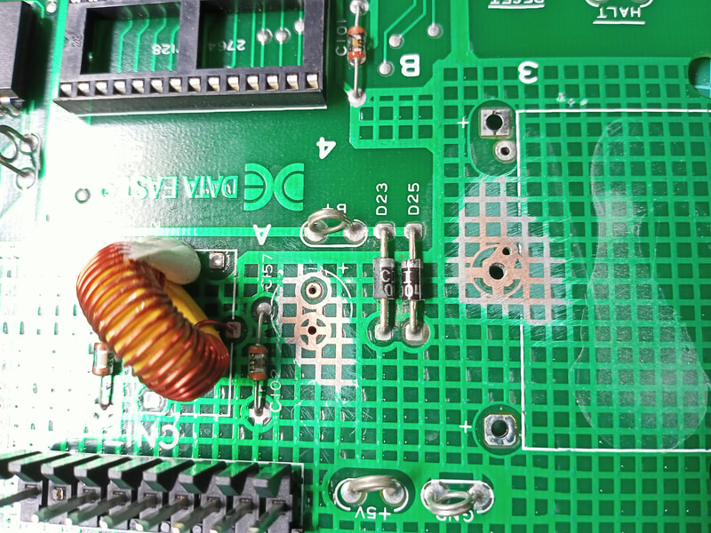
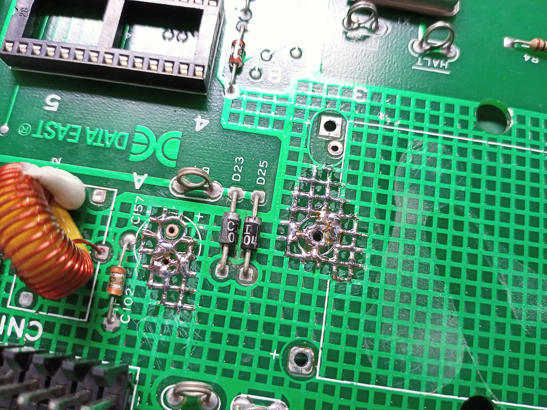
The area around the positive and negative battery connection points on the board, as well as the base of C157, needed cleaning. To do so I rinsed the area with a few drops of vinegar to neutralise the electrolytic fluid, and then sanded the area down to the bare copper. The traces in this area of the board are quite solid, so you don't need to worry too much about sanding too aggressively. I used 240 grit sandpaper on this one. Once the traces were nice and shiny, they were ready for coating. I normally use a conformal coating to protect exposes traces, however for small repair areas such as this I decided to coat the area with solder. Make sure to cover all exposes traces. It helps to "drag" the solder along the exposed traces, constantly adding more solder, to cover the area. To make things neat, you can use a desoldering gun to suck the solder back up, leaving only a thin layer on the top of the traces. This is helpful if you need to mount integrated circuits or other components close to the board surface.
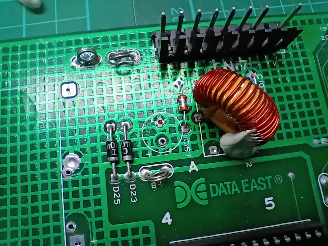
And at this point we are ready to reinstall new components. The capacitor at C157 got an upgrade (35V instead of 25V). I decided to replace the batteries with a lithium button cell, so I installed a button battery holder (Jaycar). These MPU boards are well suited to this as the through holes in the board are perfectly spaced for 20mm cell holders. The holder you get may impact D25, as this diode is mounted quite close to the original battery pack. I replaced this diode with a 1N4007 diode (Jaycar) and mounted it a little higher so it could be pushed out of the way of the battery holder. Alternatively, D25 can be mounted on the solder side of the board. 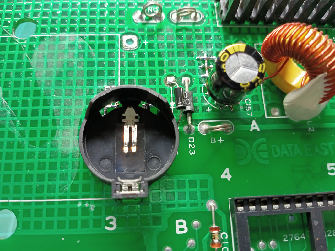
New components installed: battery holder, D25, C157.
Power supply board repairs
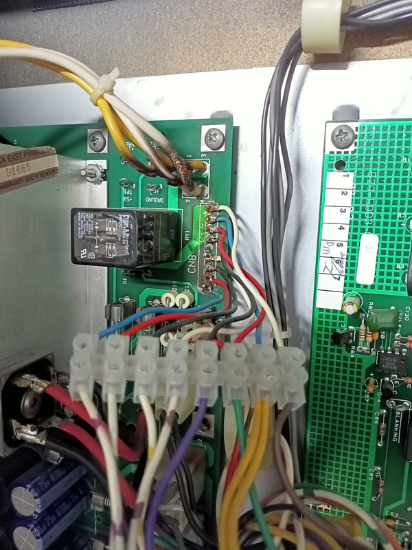
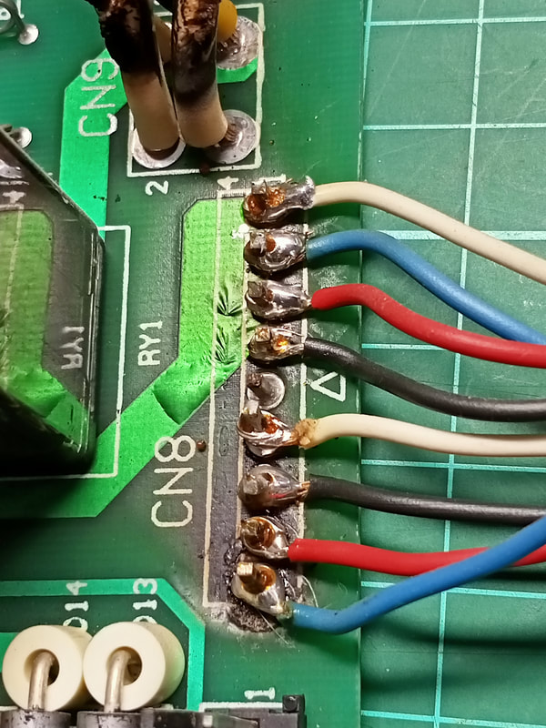
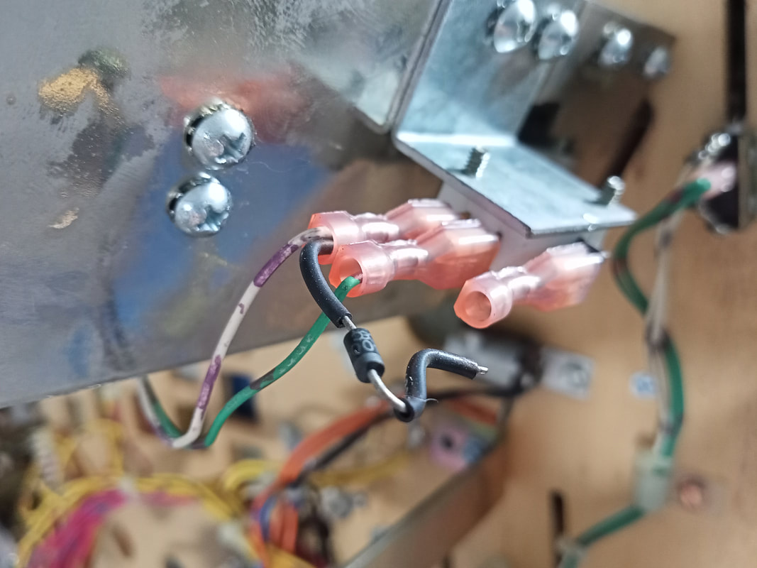
The power supply board needed a lot of help. The first area to focus on was the connector at CN8. This is the connector for general illumination lamps on the playfield, and is always tarnished and burned. A previous owner had tried to repair this issue by using a screw terminal strip instead of a normal connector, and soldering wires directly to the board. This does work, but in the backbox, it is an ugly repair. We can do better!
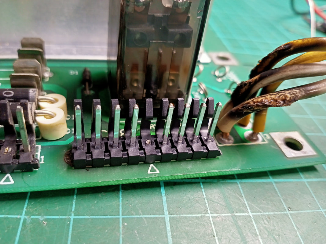
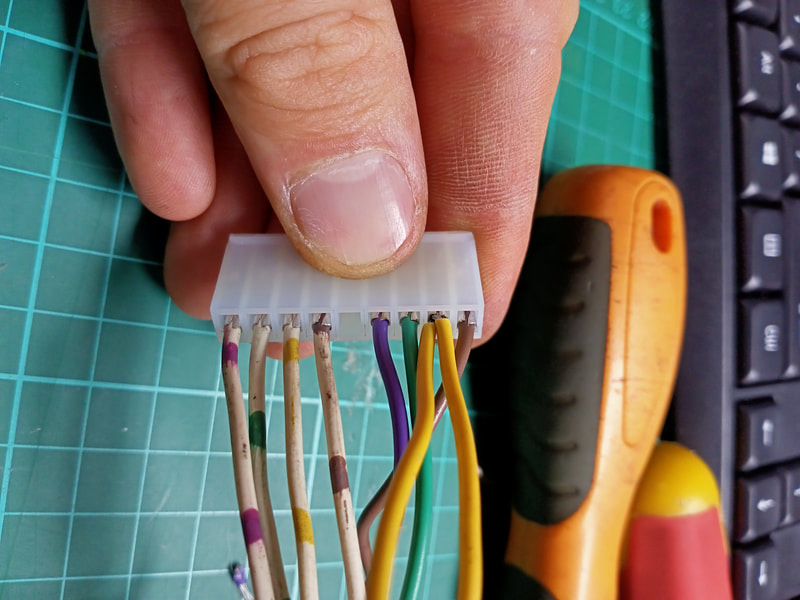
It was easy enough to cut the wires off the board and remove the terminal strip. I desoldered the pins from the board, and thankfully the underlying board material was still in reasonable condition and none of the through holes were damaged. I installed a new set of header pins (element14, RTBB, PSPA) as well as a new connector (element14, RTBB) with good quality Trifurcon crimp terminals (element14, RTBB, PSPA, Mr Pinball, Austral). The result was a much cleaner, nicer solution than the original one!
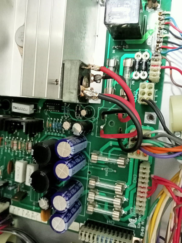
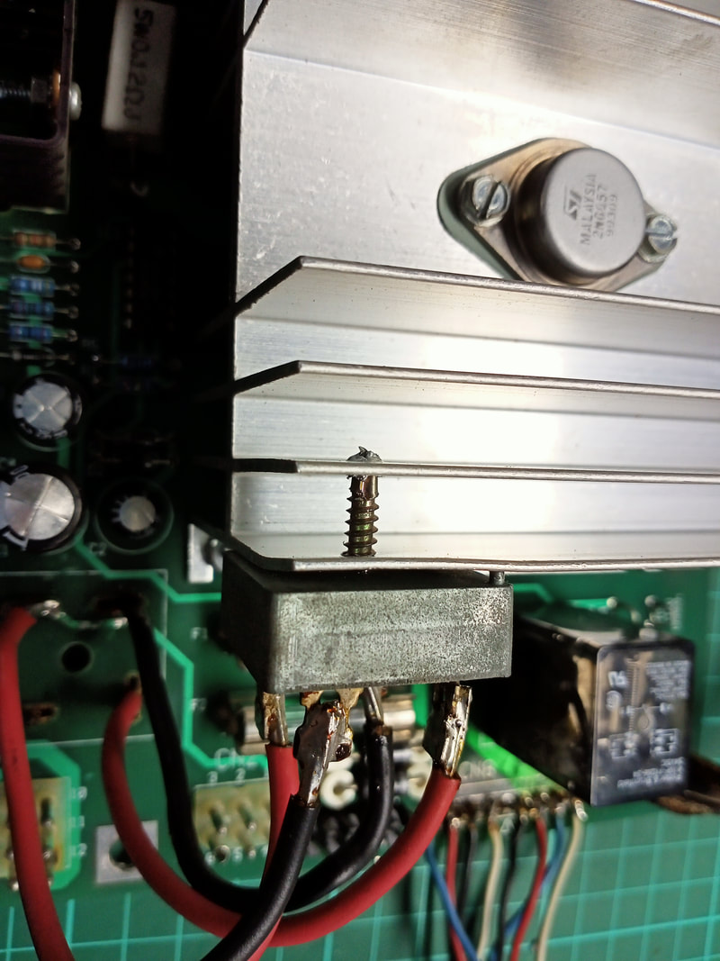
Next problem was the bridge rectifier. While not a problem per se as it was working without issue, it had been replaced at some point and screwed onto the voltage regulator heatsink. What the hell? I get that this helps dissipate some heat, but the rectifier doesn't generate that much. Oh well, time to make this right...
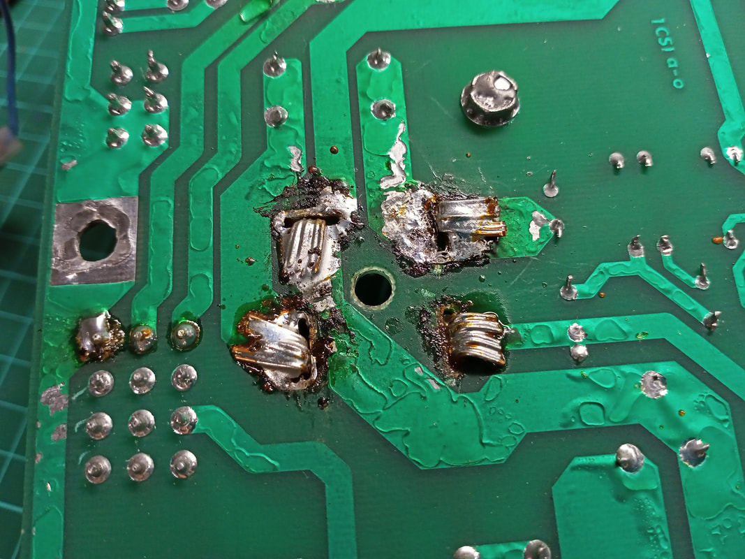
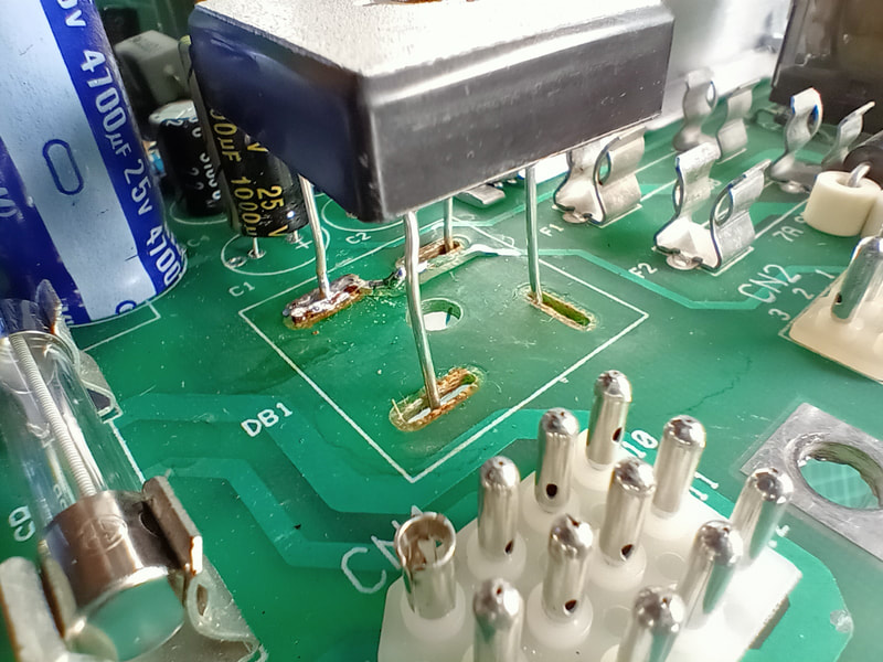
Of course, as well as mounting the rectifier off the board, whoever did this used massive wires to connect it to the board. This made the solder side of the board a mess of conductor strands, all of which were stuck in a nice pool of solder. Removing these was a pain as it required a lot of heat. The through holes on the component side of the board were damaged, but those on the solder side remained intact. This is not a big deal as only one of the bridge rectifier legs attaches to a trace on the component side of the board. The rest of the connections are on the solder side where the intact traces were. The damaged trace connected to the negative rectifier lead. I managed to save the through hole, which was still stuck to the (loose) trace. I used a bridge rectifier with wire leads (element14, RTBB, PSPA, ScribblyGum) and threaded this through the damaged through hole so that I could still use it. This meant that I didn't need to use any jumper wires and could maintain a somewhat original look. As a general rule, I always replace the lug style bridge rectifiers with wire lead rectifiers. There is no reason to use a lug style rectifier on a circuit board! The wire leads will make repair in future much simpler.
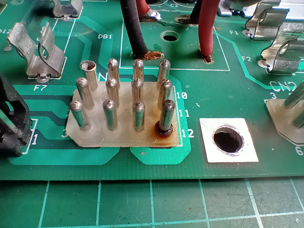
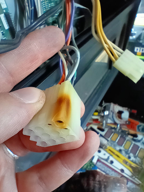
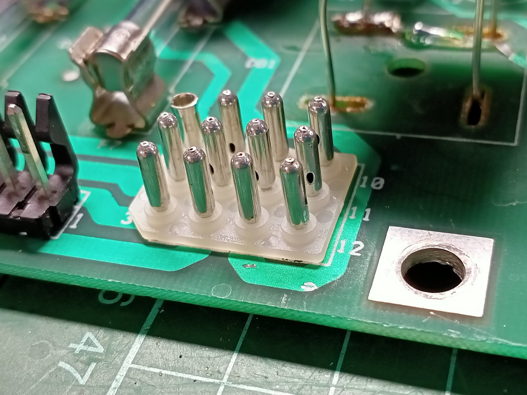
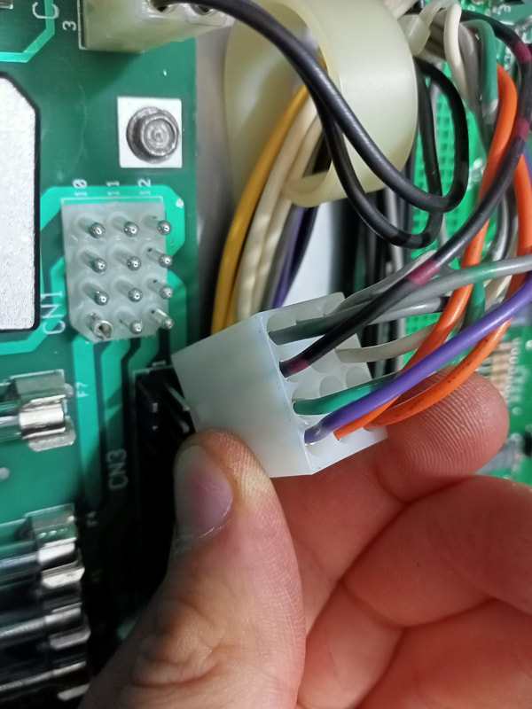
Next, the power input connector. This frequently burns up as this is where the transformer windings enter the power supply. Pin 12 was particularly crispy on this board, so it was due for replacement. If you are in a pinch, Pinwiki suggests swapping out a tarnished pin for an unused pin at CN2. However, you can buy a completely new wafer and pins, as well as female connector housing and pins, in kit form (RTBB) which makes the whole process very easy. This is definitely the way to go.
Data East fuse clips are always broken, and I had to replace a number of them on the power supply (Jaycar, RTBB, PSPA, Austral). I actually can't remember which ones I replaced, but F4 was definitely one of them. 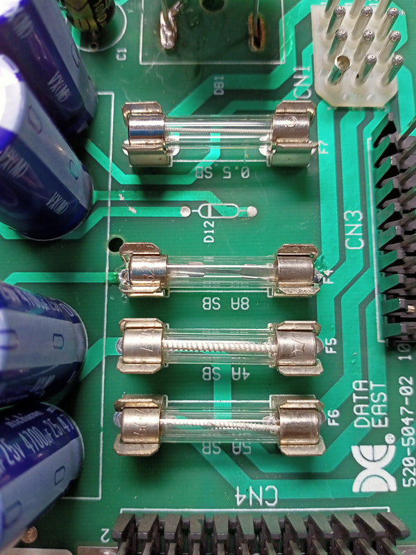
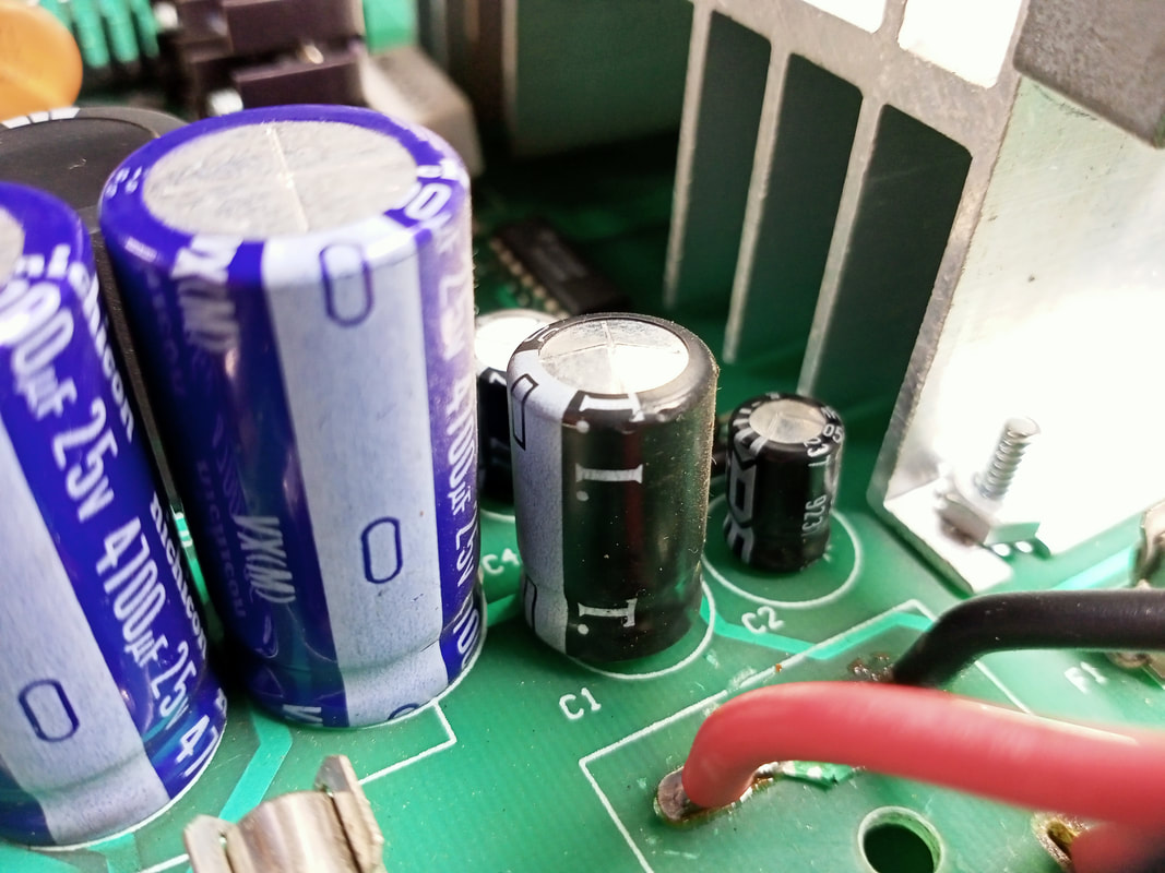
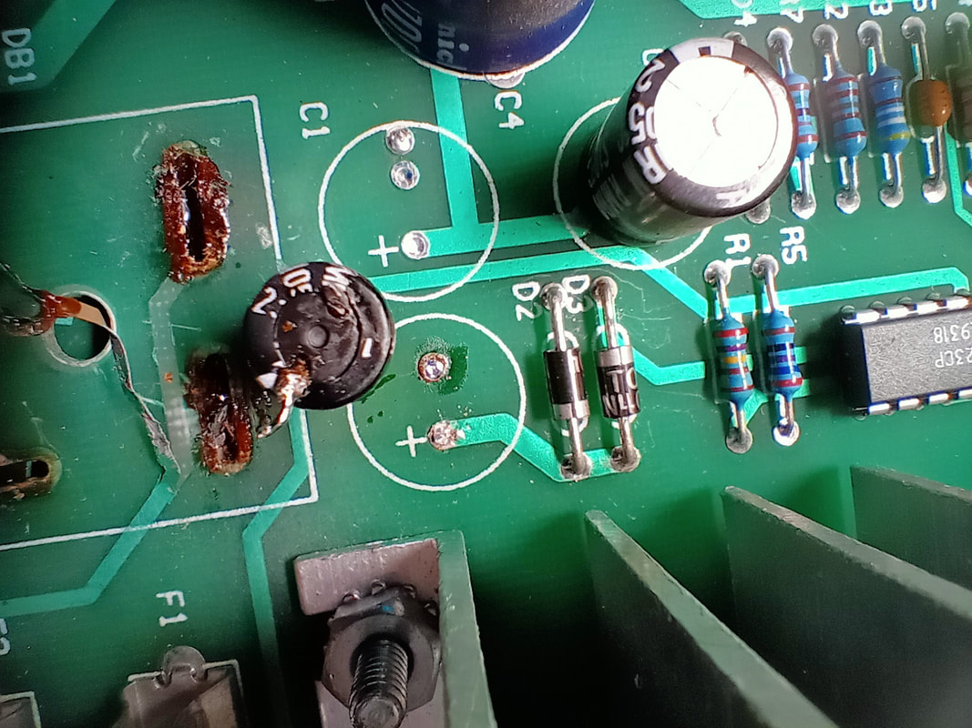
Leaking capacitors on the 5 and 12 volt circuits are a known problem on Data East power supplies, so I made sure to check all of these capacitors even though the game was able to boot. The capacitor at C1 (1000uF, 25V) was bulging, and needed to be replaced. Capacitor C2 (100uF, 25V) appeared OK from the topside, but was actually leaking badly which could only be seen when it was removed. The area was cleaned with isopropyl alcohol to remove the minor amounts of electrolyte residues.
Both capacitors were replaced, as well as C7 (330uF, 25V) which can also be problematic (but exhibited no issues this time). No other components were affected, or showed any issues. 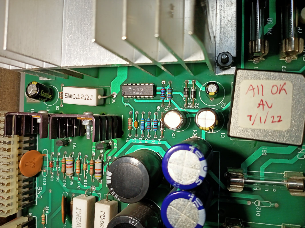
C1, C2 and C7 after replacement.
Playfield power board repairs
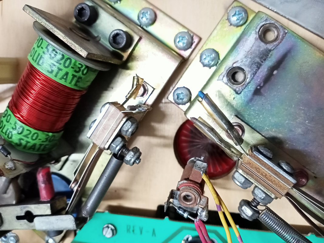
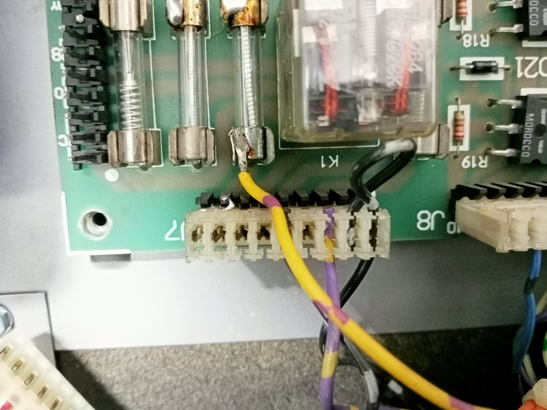
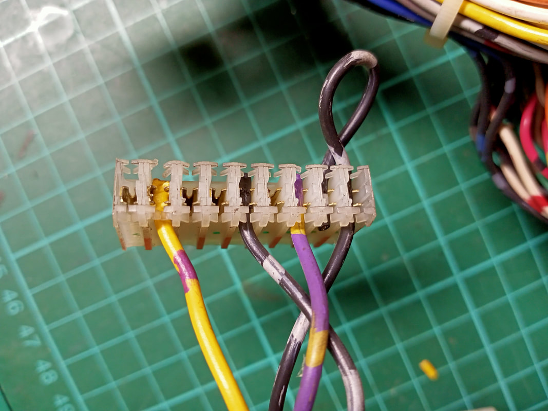
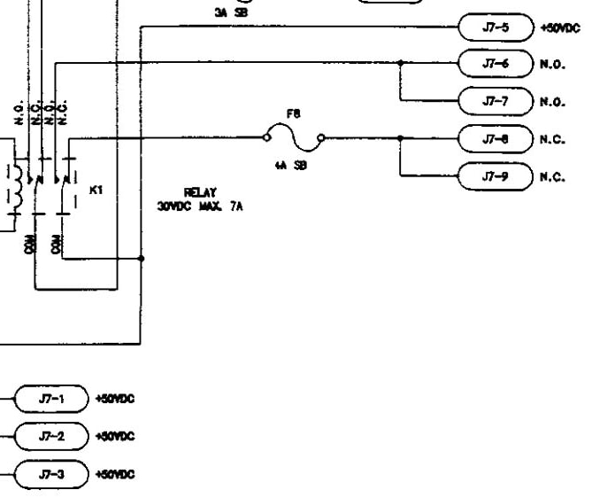
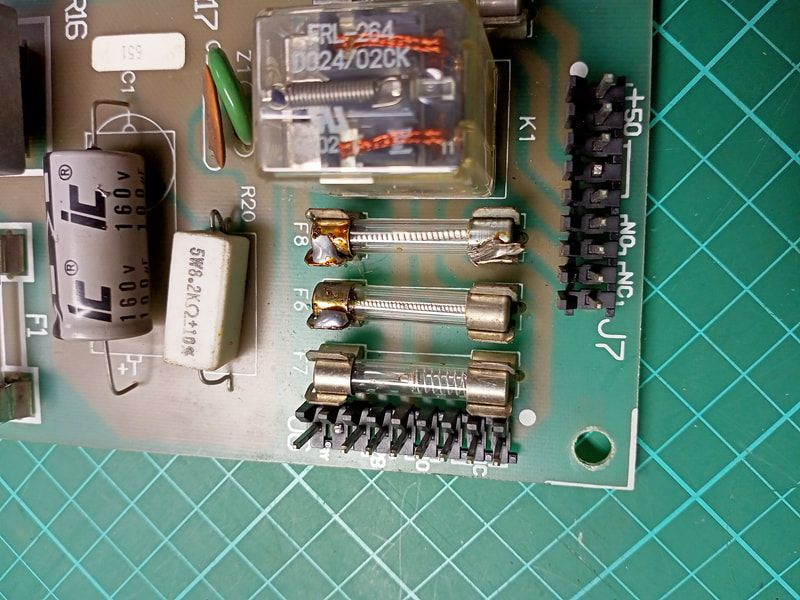
For whatever reason, someone had decided to solder the YEL-VIO wire (normally connected to J7) to the F8 fuse. This fuse is connected to pins 8 and 9 of J7, so I guess this it makes no functional difference having it attached to the fuse compared to in the connector. But I have to ask - why would anyone do this? I assume the wire fell out of the connector and someone thought soldering it somewhere would be a permanent fix. They were right, but it sure makes it hard to remove boards from the backbox! The wire just needed to be cut, and reinserted into J7.
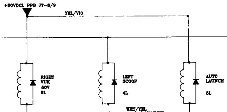
If you check the PPB board schematic in the game manual (page 65), you may discover that the pinouts at connector J7 specify 50V is sent out to the playfield via pins 1, 2, 3, and 5. Pins 8 and 9 are specified to have no connection (NC). But this doesn't make sense, because clearly the YEL-VIO wire is meant to connect here. This is a mistake in the manual. You can verify the correct configuration by checking the playfield coil wiring diagram (page 48). Here, the 50V supply for the auto launch and the right upkicker coils is depicted as coming from J7-8/9, a YEL-VIO wire. So we know the wiring we fixed above is correct.
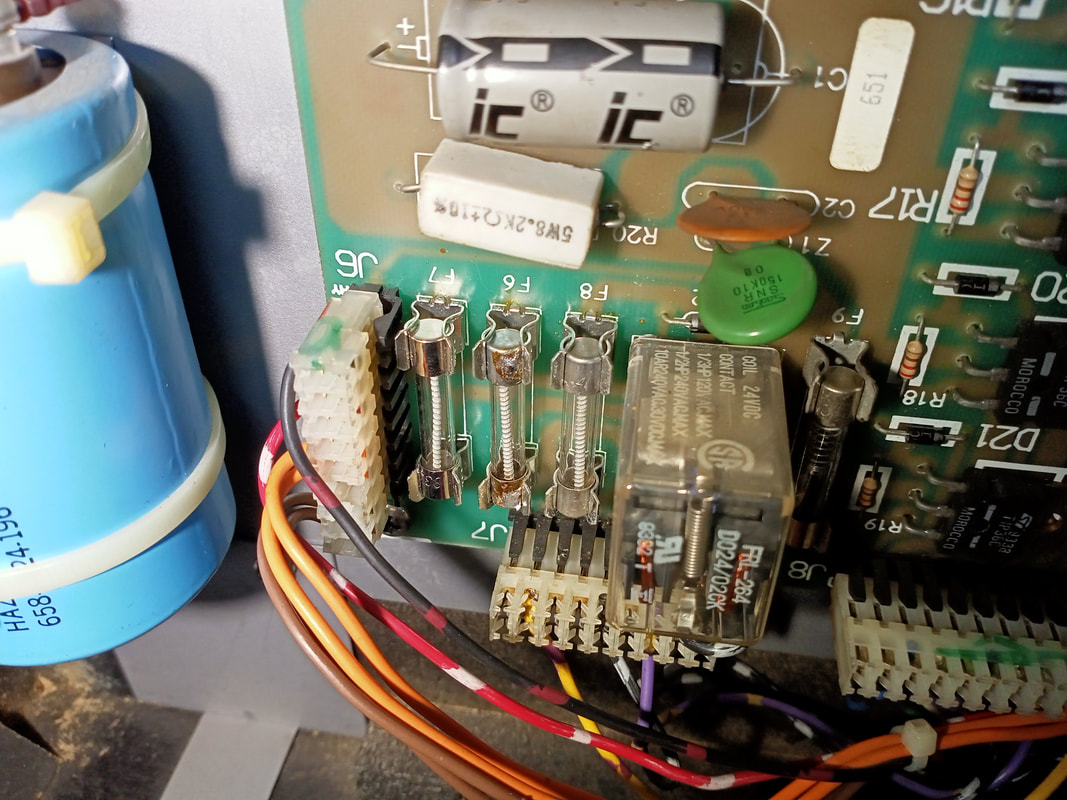
Now that the connector was fixed, I had to repair the PPB board. Fuse F8 was soldered in place, and F6 was soldered on one side - the side with a broken fuse clip. One of the fuse clips for fuse F7 was also loose, and was not holding the fuse properly. So, I did my due diligence and just replaced all of the fuse clips on both sides (Jaycar, RTBB, PSPA, Austral). Now you can actually remove and replace fuses without having to desolder the entire fuse!
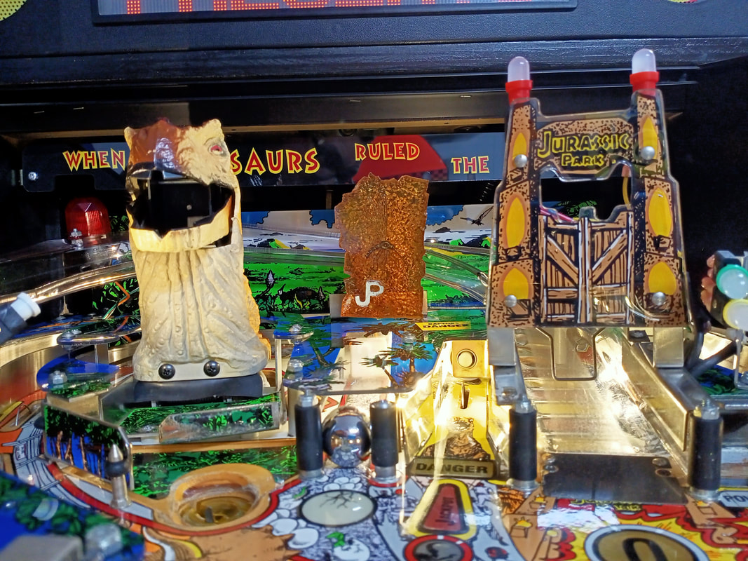
T-Rex assembly refurbishment
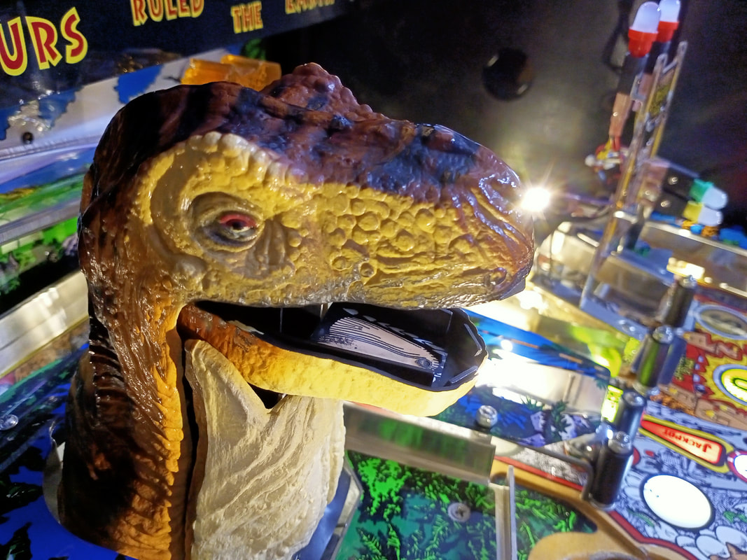
When I first got the game, T-Rex was a little sick. He moved laboriously, seemed to bind a little bit when turning to the right, and was just slow and janky. It was time for a rebuild of the assembly. The video below shows how he was moving before I started.
Disassembly of the T-Rex involves taking things apart on both the topside and underside of the playfield. There are some good instructions on how to disassemble things in this Pinside post. Basically, you'll want to turn the game on, let diagnostics run, and turn the game off when T-Rex is in the fully down position (as if he is eating a ball). This gives you easy access to the screw which is normally hidden when he is upright. There are 3 screws which secure the metal brackets attached to the collar plastic which surrounds T-Rex. Once you remove the collar, you can put T-Rex back in the upright position and move to the playfield underside. 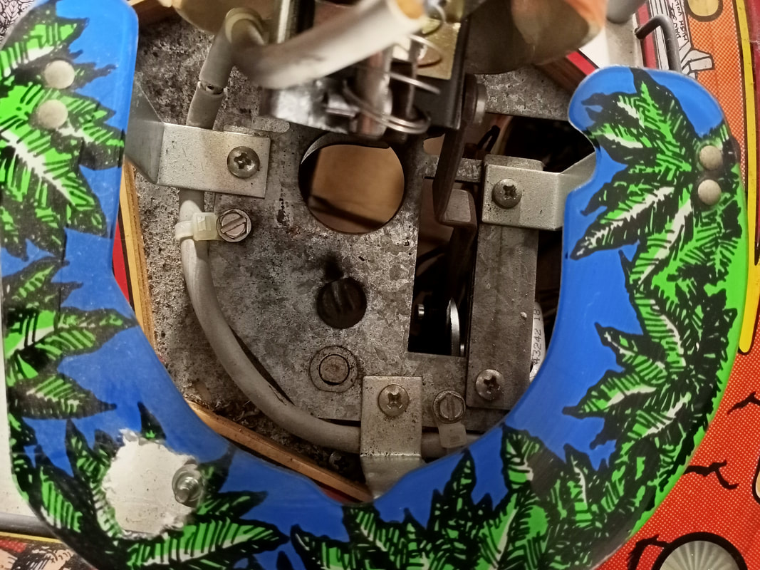
The 3 screws securing the plastic collar to the T-Rex bracket.
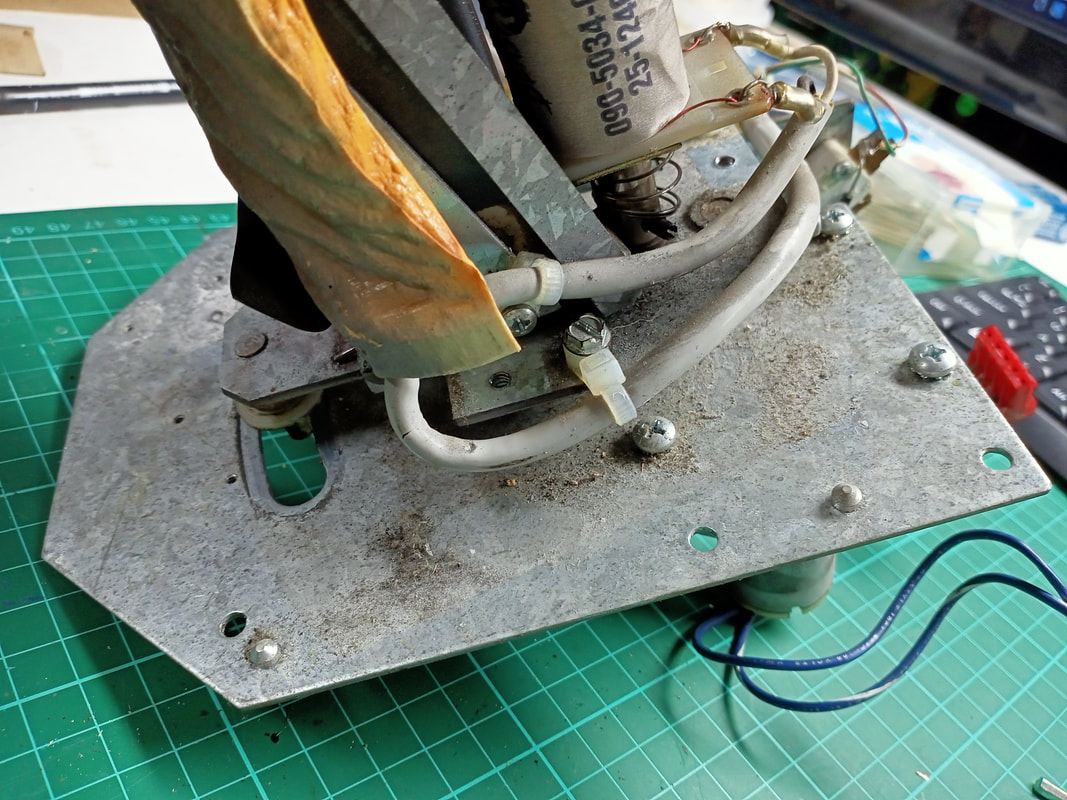
On the underside of the playfield, you just need to remove four woodscrews and the entire T-Rex mounting bracket can be pulled out. You will need to unplug connectors for the motors and switches as well as cut a few zip ties before you can pull it free from the playfield. I unscrewed each switch from the mounting plate as well - be sure to mark which switches go in which positions if you do this. Note that the left and right position switches have an insulating plate behind them, and the centre switch has two metal washers; don't loose these! The photos below show the disassembly process as well as where wires are routed and how the mechanism goes together. If you find that your left/right switches have been futzed around with, it may be because somebody was trying to implement Service Bulletin 42. Older revisions of the game software sometimes didn't recognise when the T-Rex had moved all of the way left or right, and continued to run the motor even though the T-Rex had reached its maximum range and was hard up against the edge of the assembly. This would eventually burn out the motor or destroy the gearbox. Thankfully, these motors are still available if you need to replace it (Marco). One thing I did want to do was service the left/right motor gearbox so that T-Rex movement was smooth. The gearbox seemed to work without issue however some new grease never hurt anyone. The problem I had was that I was totally unable to remove the gearbox from the T-Rex mounting plate. There is a grub screw that attaches the main spindle to the mounting plate, and I removed this, but the plate would still not budge. I tried hammering it out, pulling it in a vice, but all I was doing was bending the metal. I have no idea how this plate was fastened so securely to the gearbox, but I couldn't get it off. I inserted some new grease (Nulon Xtreme Performance) into the gearbox by removing the motor and using the motor hole. I worked the new grease in and it seemed to improve gearbox movement a little bit. Unfortunately that was all I could do in this case. 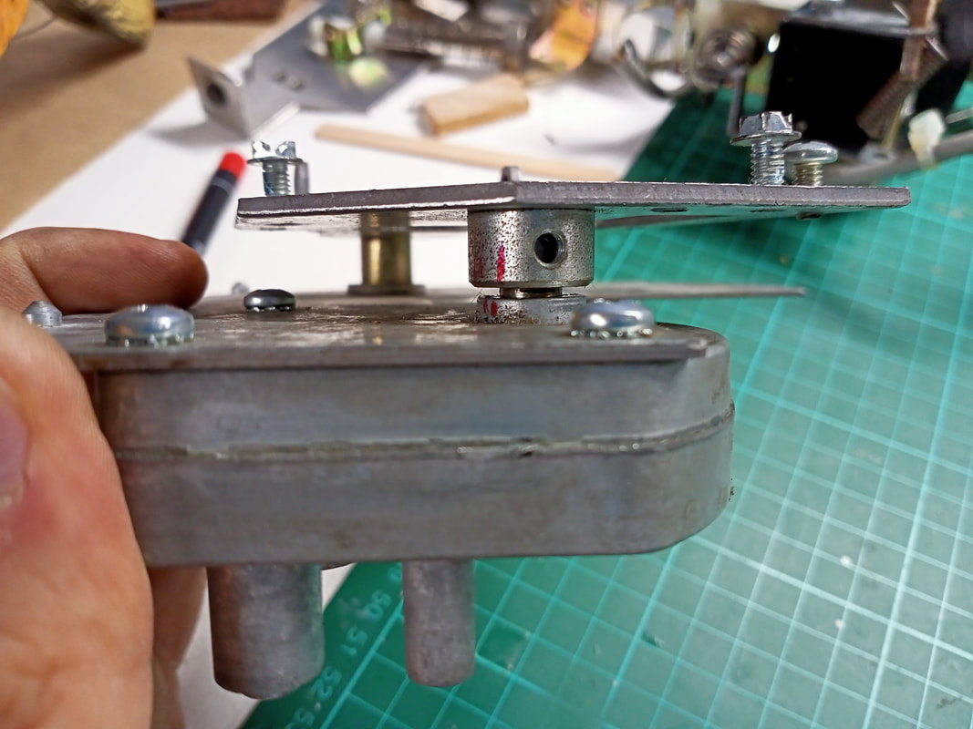
Gearbox attached to mounting bracket which could not be removed!
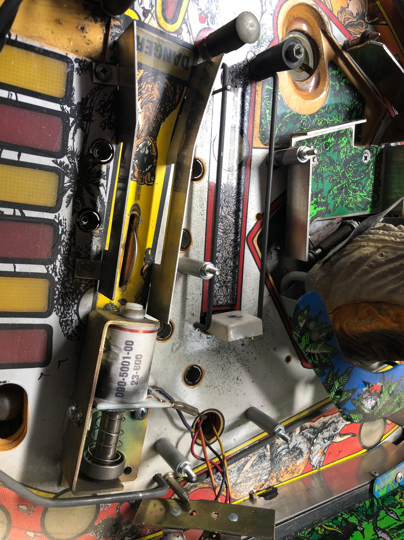
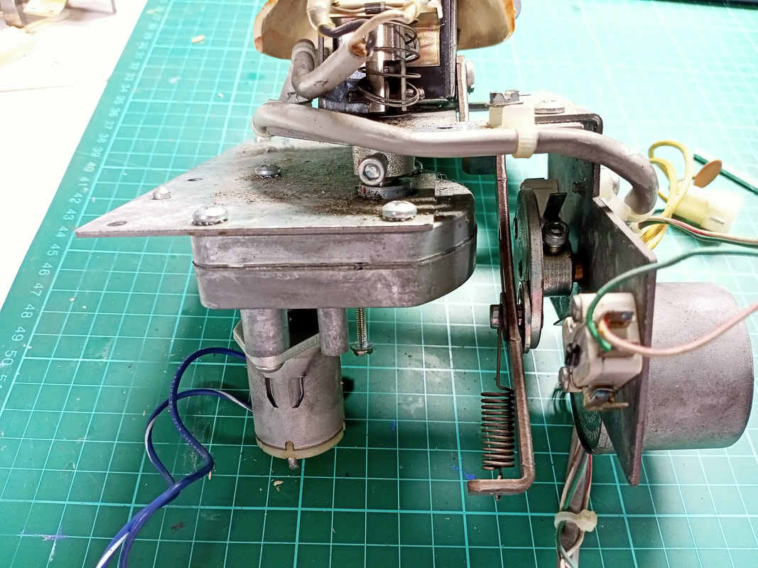
One part I could get to was the motor and mechanism for T-Rex up/down movement. This movement is controlled by a cam which spins, and has a crank lever attached to the T-Rex. As the cam spins, T-Rex goes up and down. This mechanism was very dry, so I added some grease (Nulon Xtreme Performance) to help it glide more smoothly. Otherwise, check the spring is in good condition and that is securely attached to the rotating cam. If the motor needs to be replaced, they are also available (PSPA, Marco). 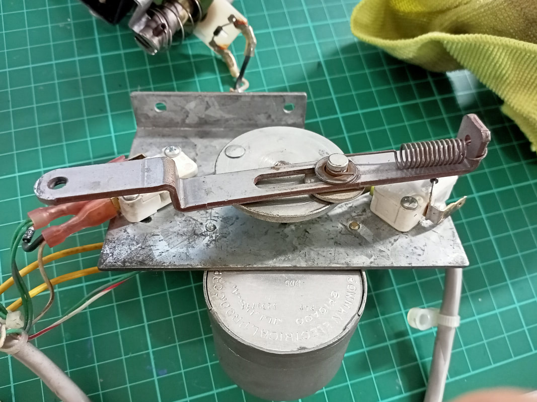
Up/down motor cam and crank assembly (before grease application).
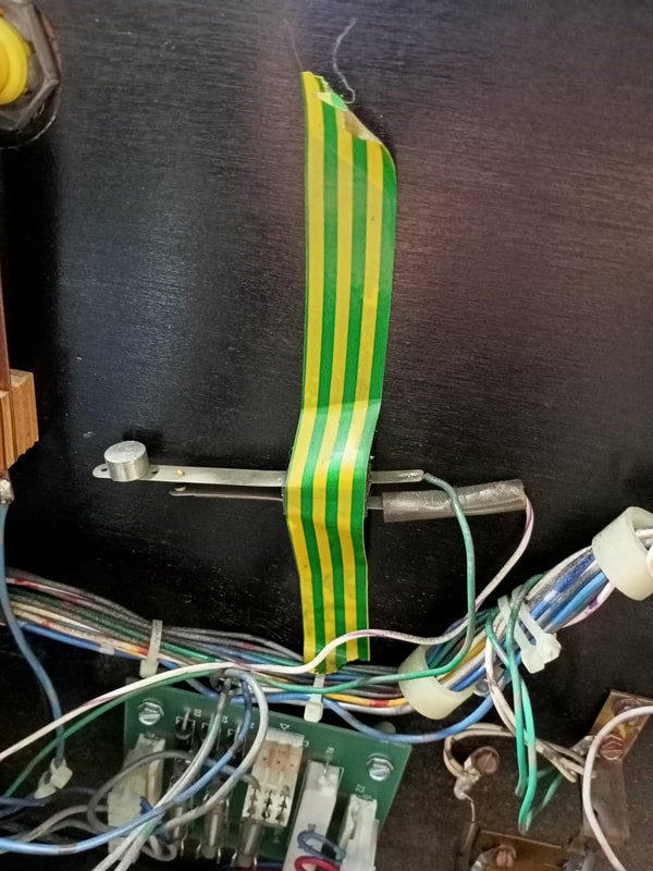
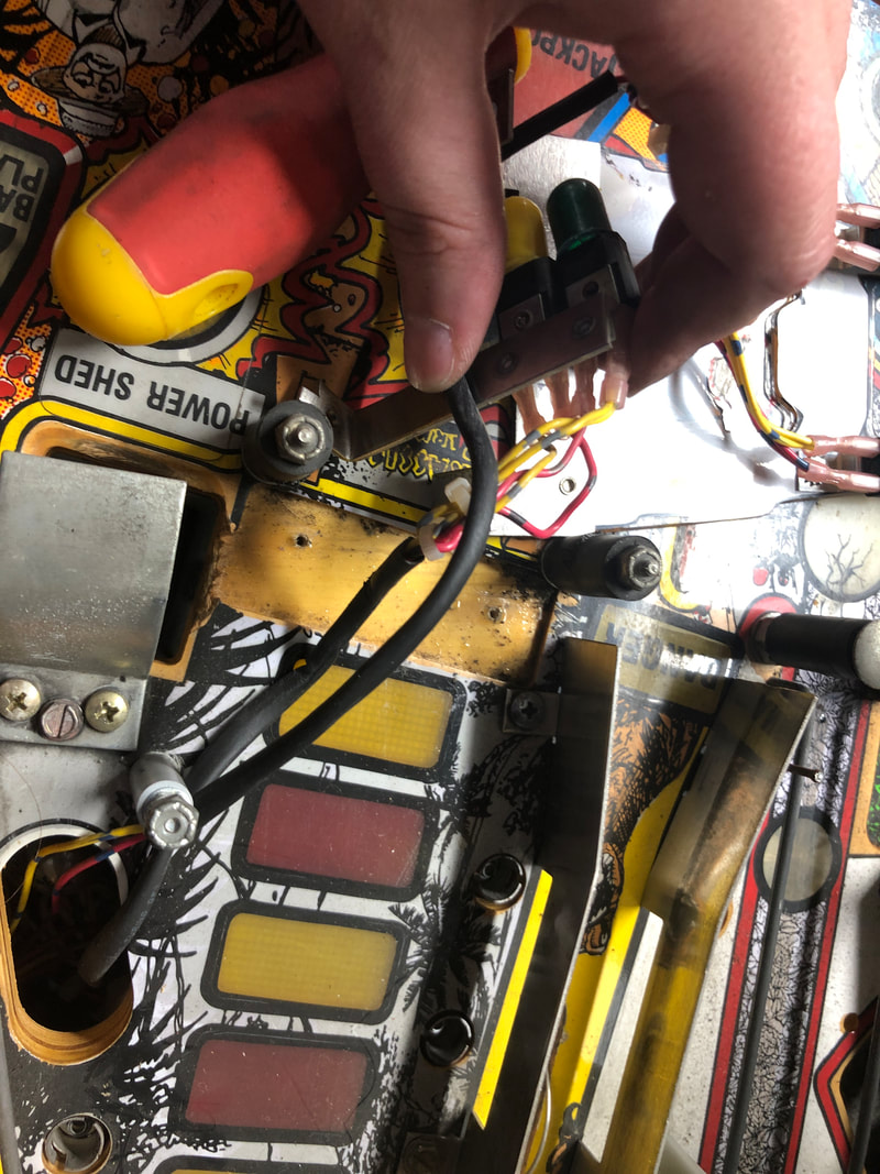
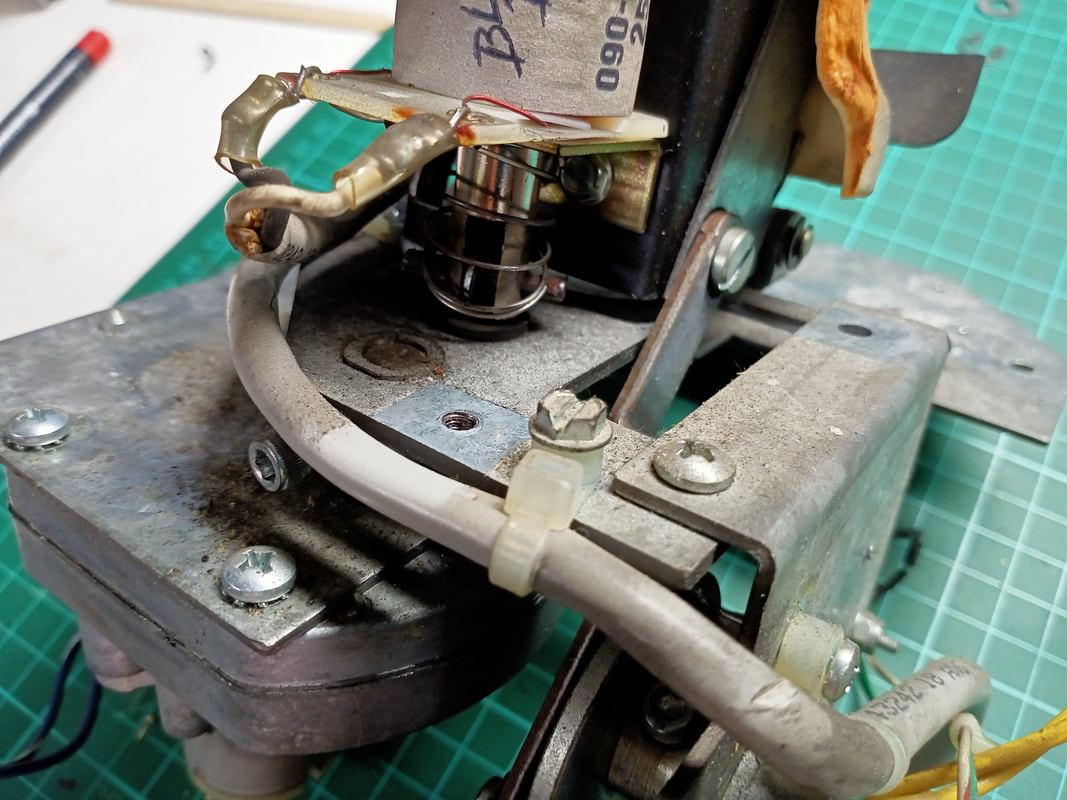
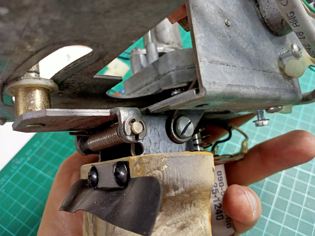
With the T-Rex in pieces, I also took the opportunity to clean the jaw coil and replace the coil sleeve. If this doesn't work well, T-Rex will drop the ball or fail to grab it when he tries to eat it. When I put everything back together, plugged it back in, and started diagnostics to test the freshly serviced T-Rex, I found that it was no longer grabbing the ball - its jaw was not closing, even though it was working fine before disassembly. Hmm. I reinspected the assembly and noticed something suspicious. Cuts in the wiring insulation which led to the jaw coil. As this assembly moves a lot and there are a lot of sharp metal corners around, there is potential for wires to break due to constant bending and flexing, or simple abrasion and cuts. When I pulled back the insulation in this area, I found a break in the white wire which connects to the jaw coil.
Fixing the wire was simple enough with another length of wire and some solder. Because I had to break away some of the wire insulation I repaired it with some electrical tape. I used a fair bit of tape so the join would withstand being bent, as this part of the wire sits to the side of the T-Rex and bends backwards. I'm not quite sure why they decided to route the wires this way, because they bend quite severely, which was probably the main cause of the break in the first place. However, there are screw-mounted zip ties to keep the cabling in place, so at least it is secure. Make sure to run the T-Rex through a few tests using diagnostic mode so you can be sure the wire doesn't get caught on the T-Rex body, mounting bracket, or playfield plastics. 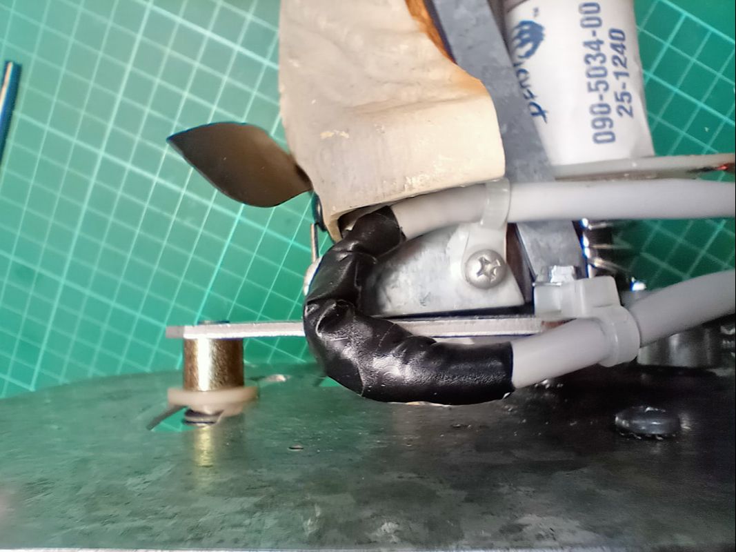
Jaw coil wire reinstalled after repair.
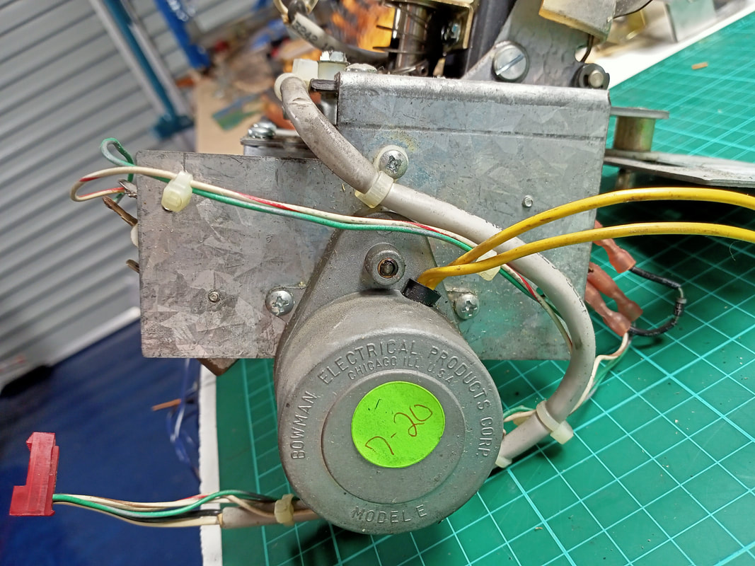
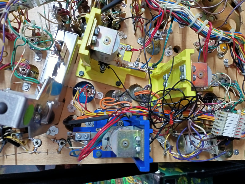
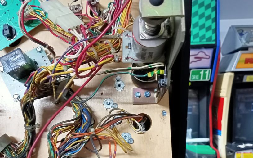
Note that if you are having issues with your T-Rex dropping the ball when trying to eat it, Data East published Service Bulletin 39 with some suggested fixes. The problem relates to the mouth bracket which holds the ball, as well as software bugs which may cause the mouth coil to lock on. A good reason to upgrade the game ROMs! One thing to keep in mind if T-Rex doesn't move left and right is that the left/right movement motor is supplied power via the shaker motor board (connector J3) in the bottom left of the cabinet. This is a bit of a weird setup, but that's how they designed it. So if you are working on the shaker motor and unplug connector J3, don't be surprised when T-Rex stops moving side to side! 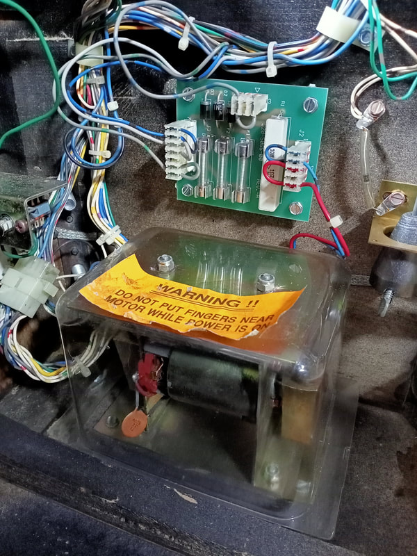
Shaker motor board showing connector J3 at the top of the board.
The technical problem people struggle most with in Jurassic Park appears to be getting the T-Rex to move properly. The most common issues appear to be cold solder joints on the shaker motor board or bi-directional relay board (under the playfield). There are many threads on Pinside about other movement issues and a Data East service bulletin which cover the operational theory of how the T-Rex moves, how the motors work, and where the necessary power comes from. These resources are a great starting point if you are trying to diagnose T-Rex movement issues:
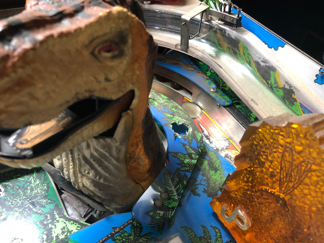
Thankfully after the rebuild, I had no issues with T-Rex's movement, so no further modifications were required. Some people have suggested adding a diode to fully rectify the current going to the T-Rex motor, which reportedly helps a lot with smooth movement. I haven't done this modification, but the theory behind it seems sound. The main thing is to ensure you have the latest game ROMs, as these run the motor more efficiently than earlier game ROM revisions. Once everything was plugged back in and installed, it seemed that T-Rex moved more consistently and smoothly than before. A definite improvement. He grabbed the ball and ate it as required, as well as moving from side to side without binding. The video below shows proper movement during T-Rex diagnostics at boot-up. A note on T-Rex cosmetics. Spot the difference between the two images below. Apart from one image showing an absolutely filthy game while the other looks to be pristine, the main difference is at the base of the T-Rex body. There is a black flap which is supposed to cover the large torsion spring at the bottom of the T-Rex. It was mounted completely incorrectly when I first got the game in, facing upwards and on the front of the T-Rex. Instead, the flap should point down and go behind the T-Rex body moulding.
If you just took a look at your game and realised that there is no torsion spring installed at all, that may be because you have an early production game. The torsion spring was added as described in Service Bulletin 41 in order to help the motor raise the T-Rex after eating a ball. If yours is absent, simply find a torsion spring that threads on top of the "Dino Shaft" (item no. 10 in the image below). However, make sure it is not too strong that the motor then struggles to lower the T-Rex. 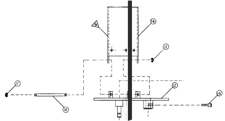
T-Rex assembly diagram showing the main body of the T-Rex.
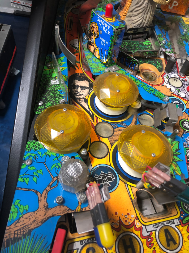
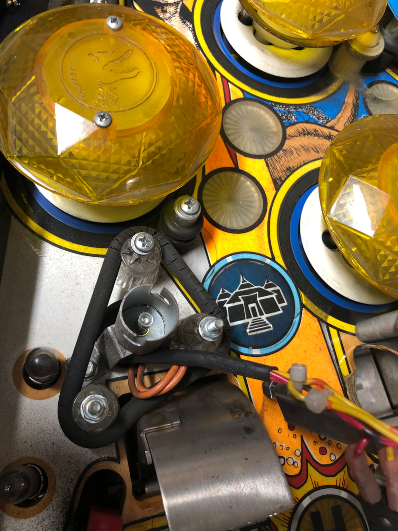
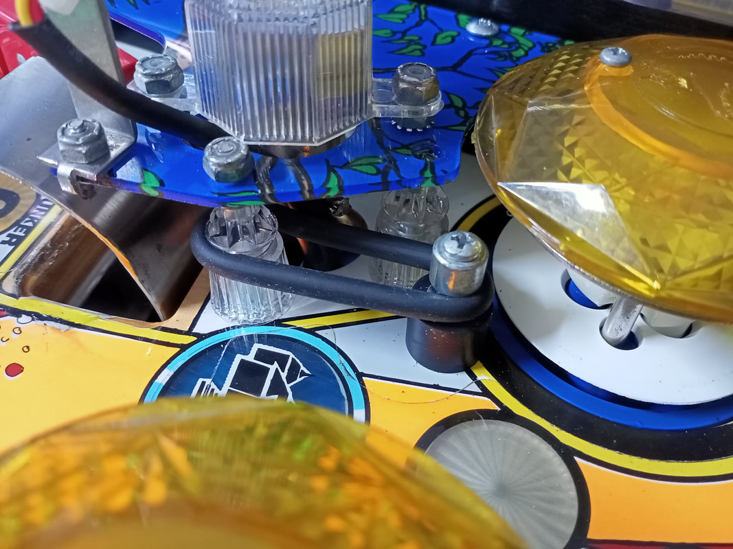
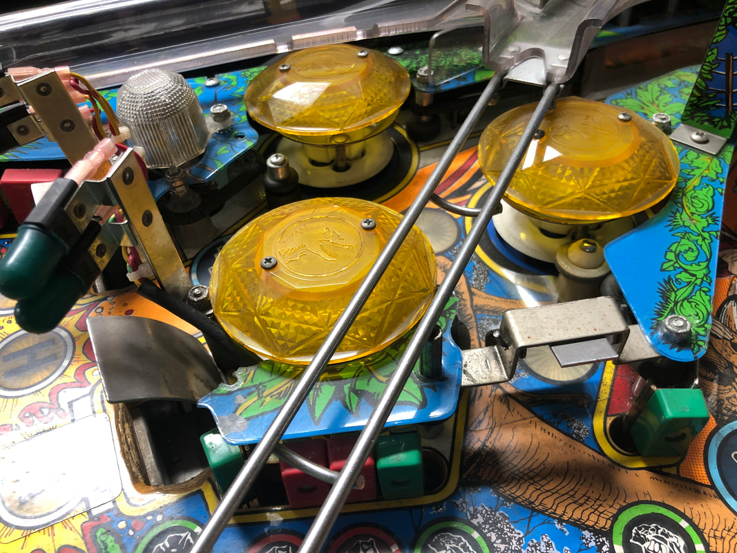
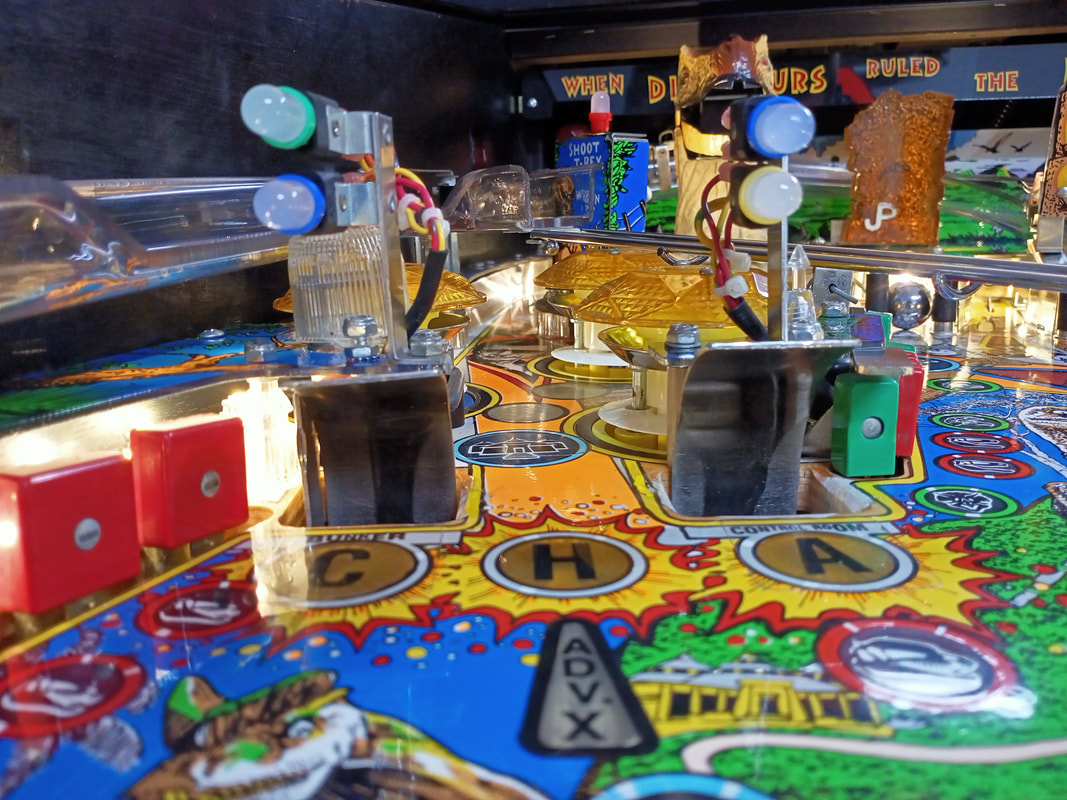
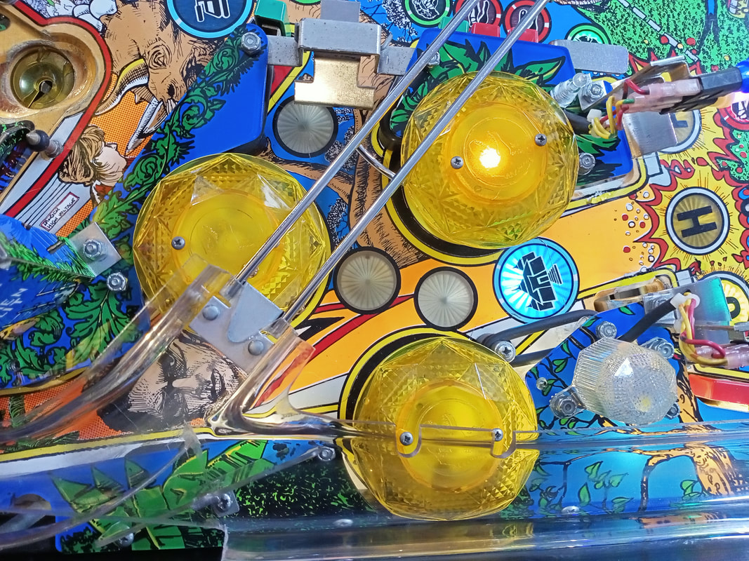
Pop bumper refurbishment and post and rubber placement
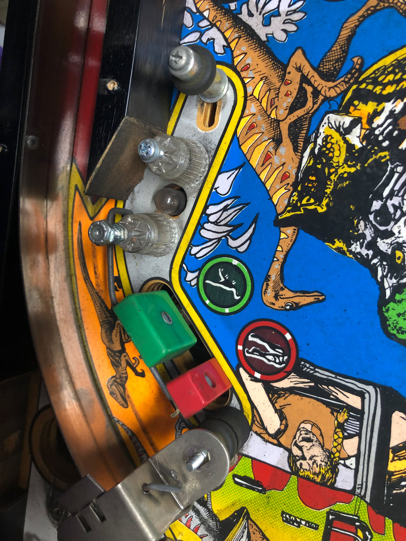
There are some weird rubber ring placements on Jurassic Park. For example, there is a rubber ring which encloses the dome flasher socket in the pop bumper area. This same ring wraps around the Bunker scoop, which causes the rubber to chafe and break. Why is there rubber in an area of the playfield the ball will never enter? This is pointless. I replaced the ring with a smaller one, and placed it around the star post and metal post on the outer edge, closest to the active playfield area. This is a much cleaner look and, in my opinion, better use of the playfield posts.
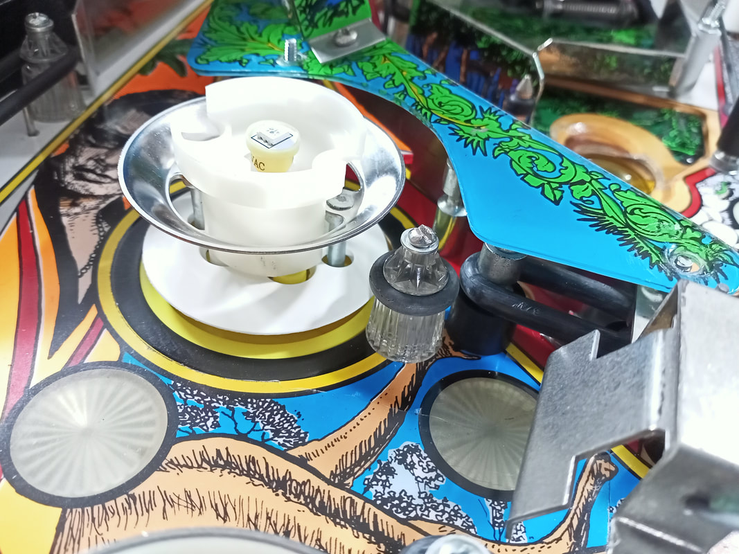
There was a star post adjacent the top pop bumper which I didn't realise wasn't supposed to be there until I looked at some images of other Jurassic Park machines. My guess is an operator put this post here because balls can potentially get stuck between the rubber ring and the pop bumper. A ball can fit into this slot, but it would be immediately ejected from this area by the pop bumper, so the post is not really necessary. I removed the post, filled in the hole with putty (Selleys Knead It) and painted over it. There was one small patch I forgot to paint (whoops), but this spot is hard to see from a player's position so I let it be.
The pop bumpers got a complete service and clean. Parts replaced included lamp sockets (RTBB), two rusted rod and ring assemblies (PSPA, Austral, Mr Pinball, RTBB), wafers (RTBB, PSPA, Austral), and coil sleeves (RTBB, PSPA, Austral, ScribblyGum). Two of the bumper housing brackets were also cracked at the screw hole mounting points, so these were also replaced (RTBB, PSPA, Austral).
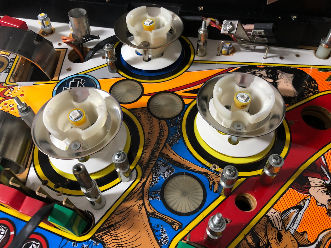
All three bumpers fully serviced.
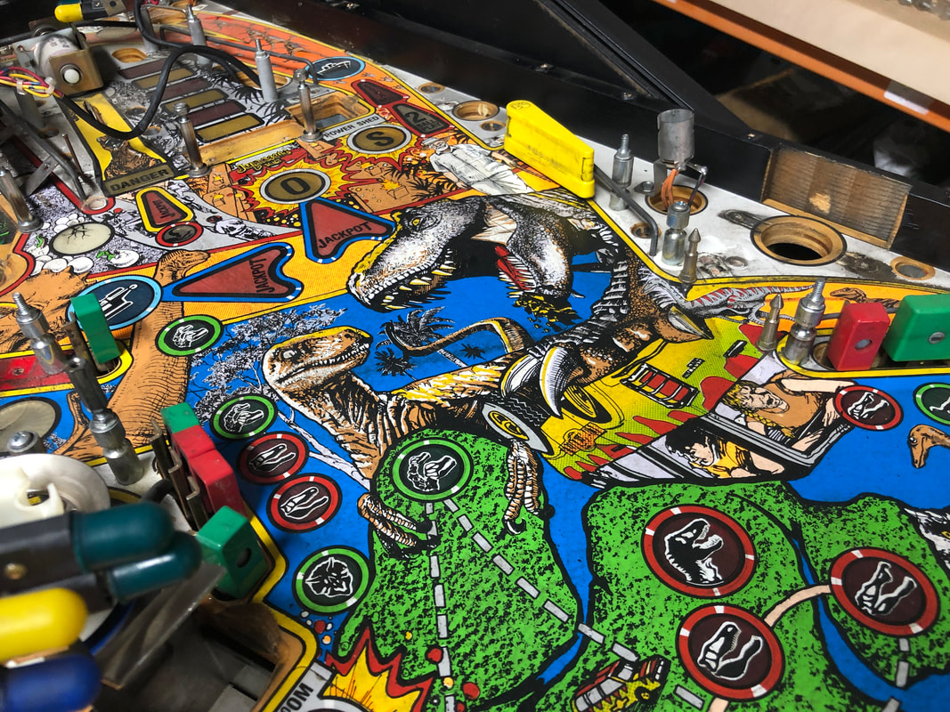
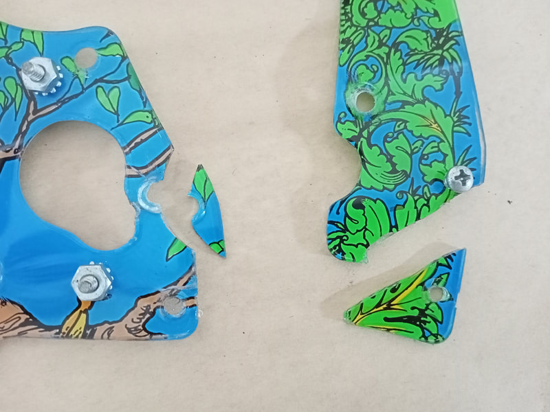
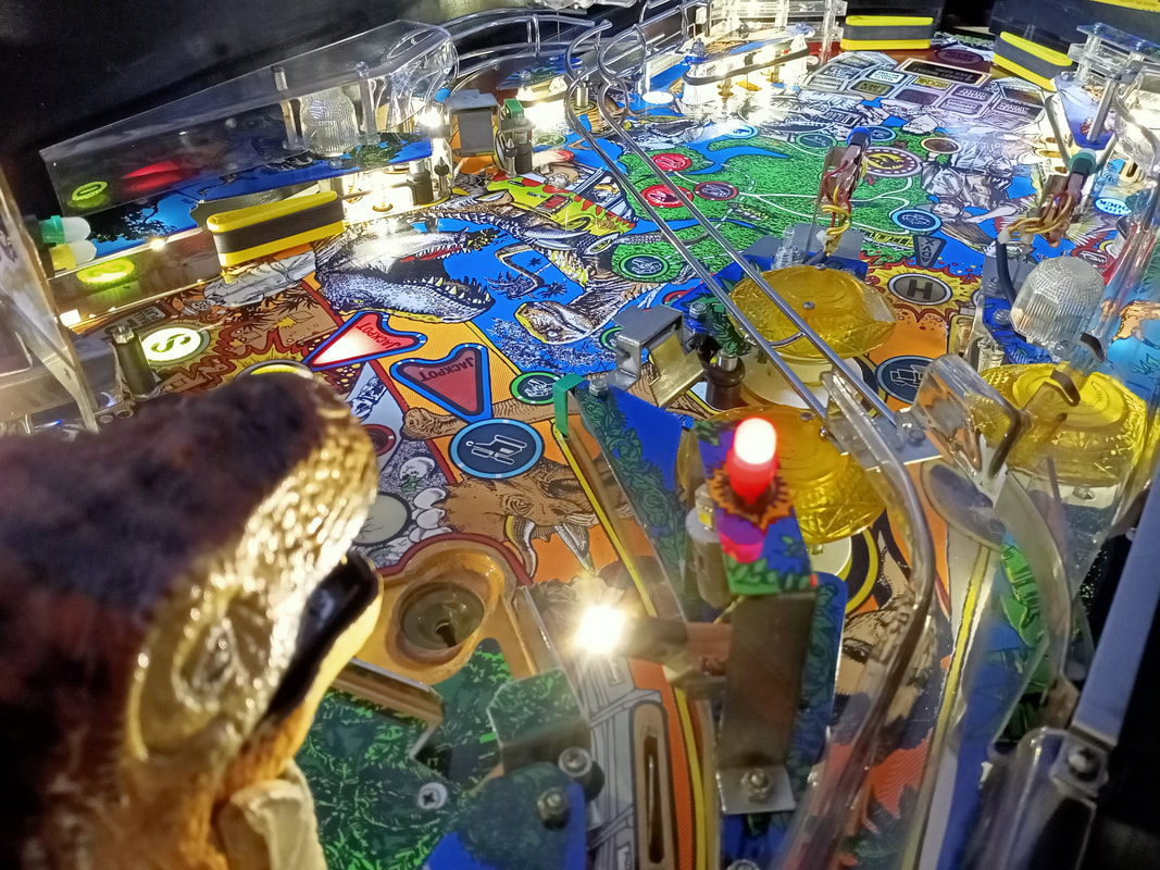
Plastic set installation
As is always the case with games of this era, several playfield plastics were broken. Depending on the number of plastics broken and how severely broken they are, I tend to assess whether the cost of a new plastic set is worth the additional expense when compared to how much the broken plastics detract from the look of the game. With the number of plastics broken on this game, a new plastic set was worthwhile. The ugliest broken pieces were the plastic above the Control Room scoop (completely snapped off), and a hole which had been savagely cut in the collar behind T-Rex (provided access to a screw).
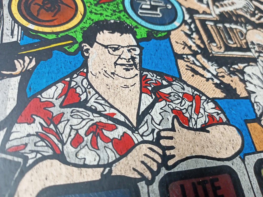
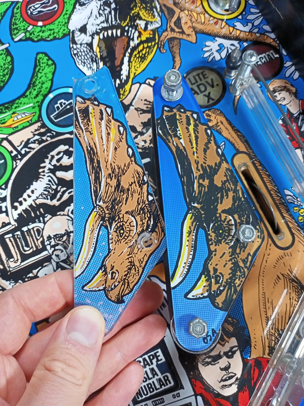
If you are after a new plastic set, the only option is a set made by Classic Playfield Reproductions (RTBB). This is a complete set which also includes some promotional plastics (key fobs) and two sets of slingshots (blue and red). Be aware that the reproduction plastic set is darker in colour than the original plastics, and has much less detail in the graphics. This is still much better than broken plastics, but if you only plan to replace a couple of individual plastics instead of the whole set, you might find the difference between new and old plastics a little jarring.
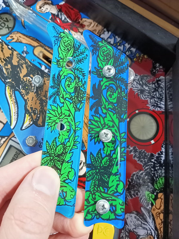
However, the red and orange colours in the original plastics is often badly faded, and this is where a new plastic set really makes the game look good again. 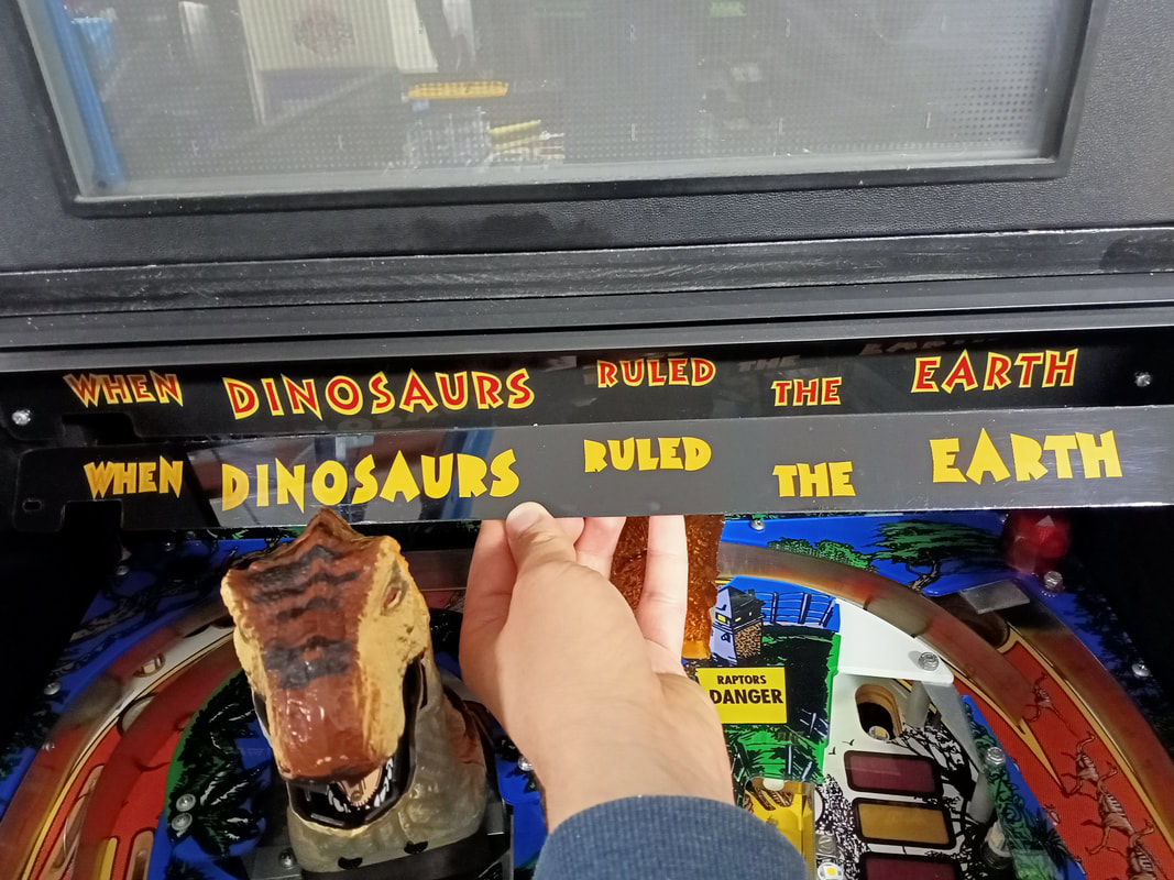
New plastic installed, original (faded) plastic in my hand.
Of course, a new plastic collar around T-Rex was also included in the plastic set. You will need to remove the metal brackets from the original plastic (six rivets) and reuse them on the new plastic. Instead of using rivets to secure the new plastic, I simply used nuts and bolts so things could be taken apart more easily in future. 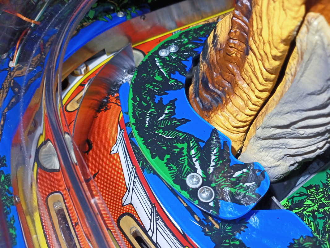
New plastic collar plastic secured with nuts and bolts.
Despite the drawbacks of the reproduction plastic set, it's fantastic that we have reproduction parts like this available again. When installed as a complete set on a game, they really do make it look brand new again. 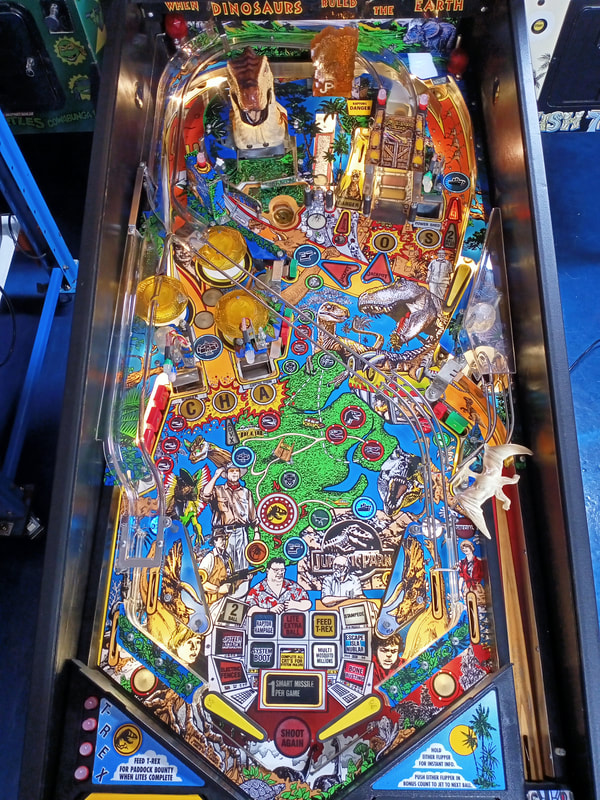
New plastic set fully installed.
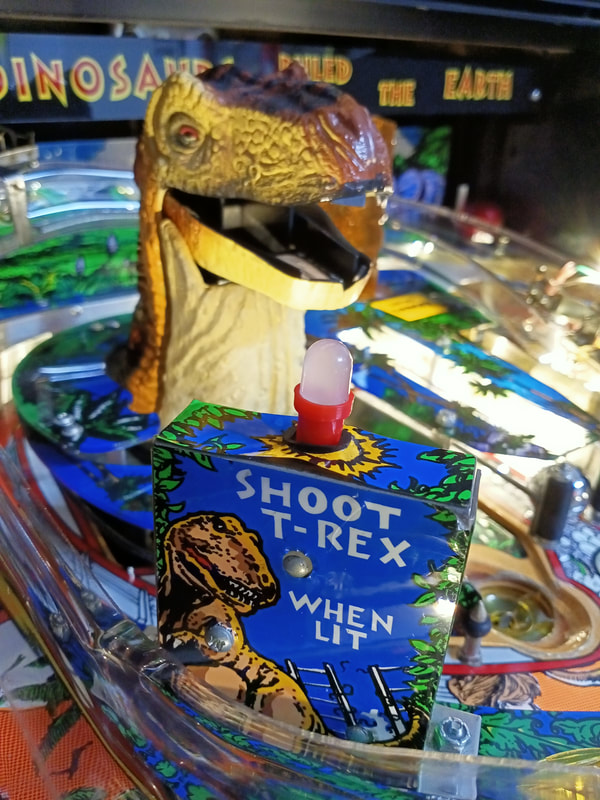
Apron lamps not working
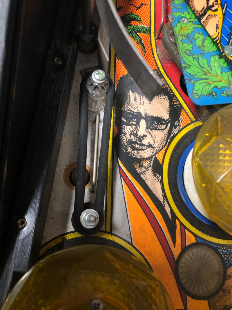
The T-REX apron lamps were having issues. The E and X lamps would not light up. The new LED lamps were not the issue as they worked fine in other sockets. I narrowed down the problem to the sockets themselves, by connecting a temporary socket in parallel to the non-working socket. A working lamp in the temporary socket but not the original socket meant that the original socket was toast. No surprise, as every game I look at has a couple of sockets gone!
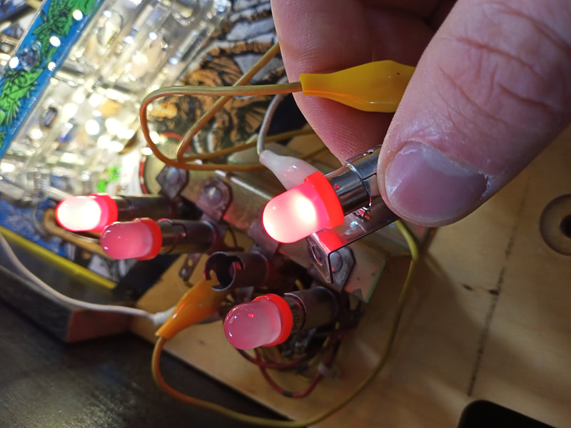
Testing lamp sockets with a temporary socket connected.
So, it was time to replace the socket. These sockets are frustrating to replace, as they are riveted to a small metal bracket under the apron. You will need to drill or punch the rivets out. I had better luck with the drill, personally. The other issue I had was that I could not find a compatible socket to match the original ones in my toolbox. These are not regular playfield sockets, as the mounting brackets are much shorter (stouter) than those used under the playfield. I tried bending a couple of longer brackets to the right length, but I just ended up with a mess of twisted metal. Eventually I discovered that a #555 wedge socket was the perfect size for this application (RTBB, PSPA). With the bracket flattened out, the socket sat at just the right height for the lamps to protrude through the holes in the apron. No need to bend or otherwise modify the socket bracket. 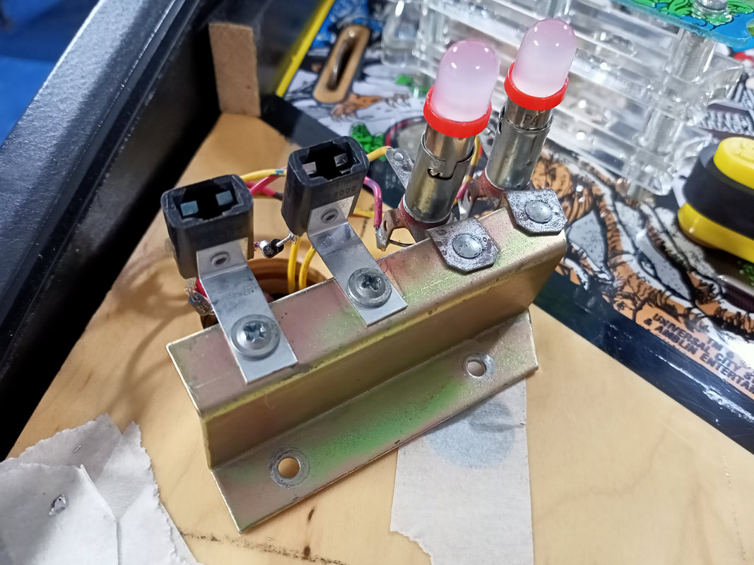
Installation of two new sockets on the bracket.
There are a couple of errors in the manual relating to these apron lamps which are worth of noting. Firstly, the "T" arch lamp is listed twice on the playfield lamp wiring diagram (page 51). It is labelled as lamp number 2 and 37. However, lamp 37 is actually "T-Rex map" as indicated in the playfield lamp locations diagram (page 29). Secondly, the lamp numbers of the apron lamps are 2, 47, 48 and 60, respectively. However, lamp 48 is labelled as "C" arch instead of "E" arch (last time I checked there is no "C" in "T-Rex"). 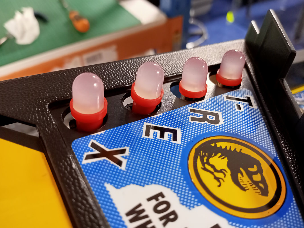
Lamp sockets fixed and LEDs installed.
Flasher issues
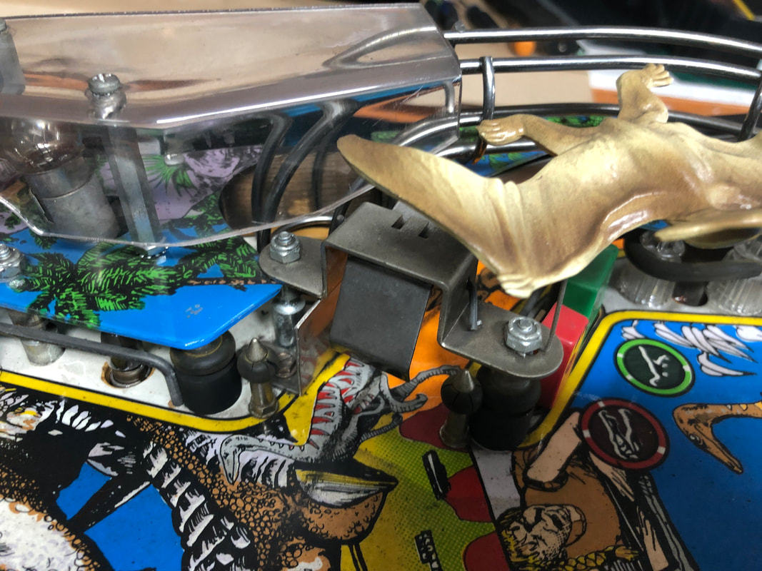
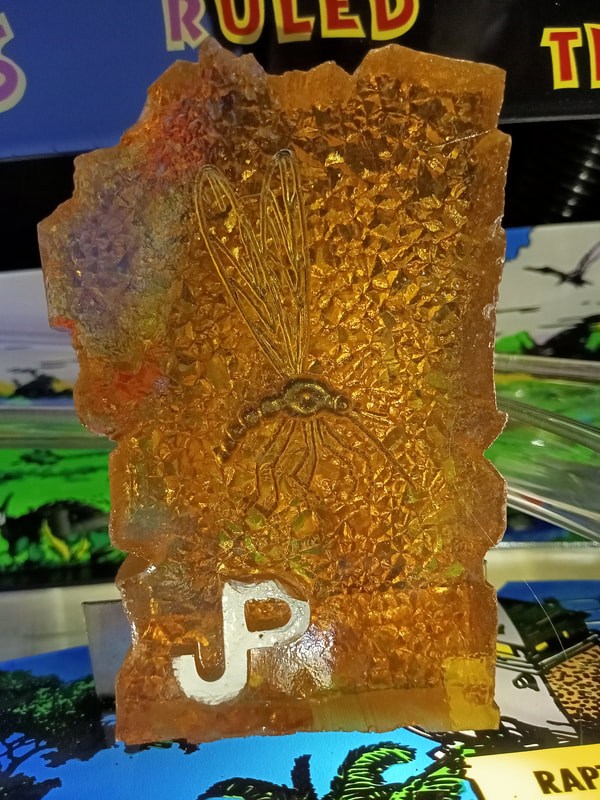
This first issue was discovered when disassembling the game. There was a magnet stuck to a flasher and controlled lamp socket behind the amber mosquito. There is a potential here to short flasher voltages to the controlled lamp matrix. Not good! I have no idea how this didn't cause any issues with the lamps, but I can't recall whether this flasher and lamp were in working condition or not. Either way, when replaced with LEDs, the sockets and LEDs worked fine, so no harm done.
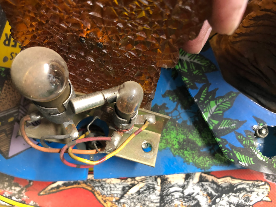
Magnet shorting the flasher and general illumination lamp sockets together.
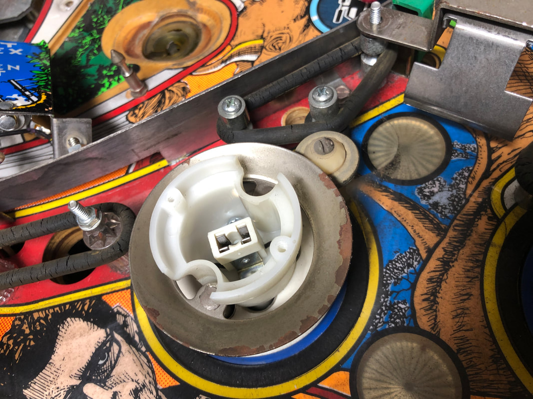
The second issue was one of my own making. After installing LED flashers throughout the playfield, I found that one string of flashers did not work. These flashers were the raptor pit flashers (designated 1R), including two flashers under the playfield (visible through holes in the playfield) and a flasher in the backbox. None of the flashers would light up. I checked a few things, including verifying power was at the flasher socket, the LEDs themselves were working, and wiring in the backbox was all intact (PPB and CPU board connectors). All of this checked out OK. I then began inserting each flasher one by one to see if I could narrow the problem down to a single socket in the string. The flashers worked until I got to the last socket on the playfield. Once I inserted the flasher into this socket, they all stopped working. The socket looked fine however I realised the problem as soon as I removed the socket from the playfield and looked inside it. A nut had fallen in and was shorting the socket. This must have happened during playfield disassembly; I dropped a few nuts and screws during the process and I guess one of them ended up here! 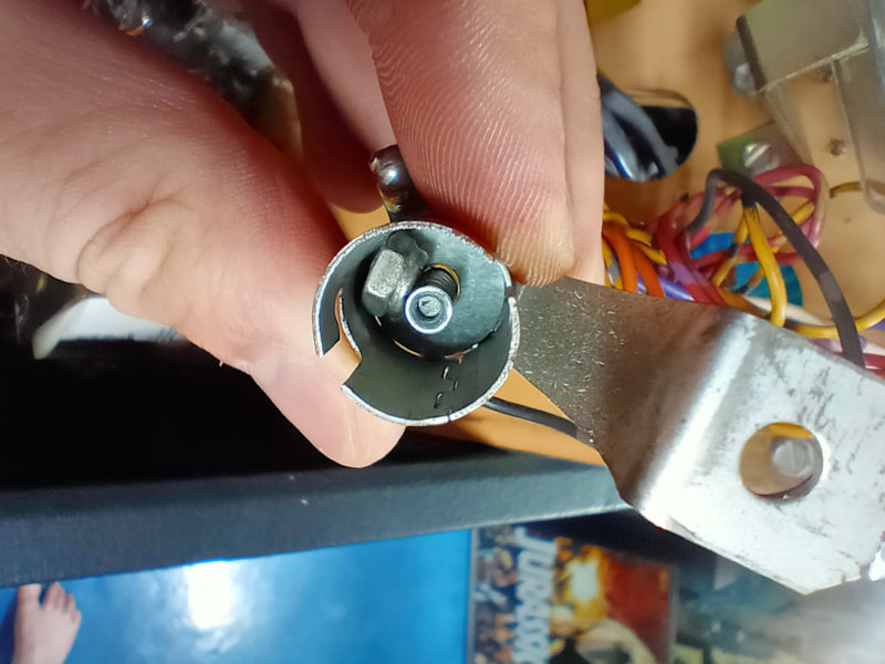
Nut shorting out a flasher socket.
Another misprint in the manual to note regarding these flashers. The wiring diagram on page 31 and 48 indicate that each flasher string contains four flashers. However, the string on 1R only contains three. Mystery coil power wire
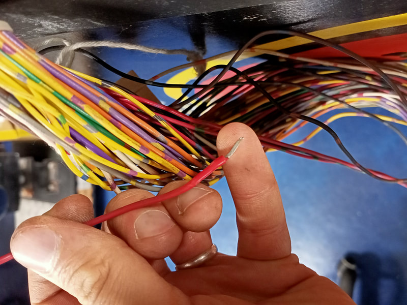
One strange thing I noticed under the playfield was that there was red wire connected to the right VUK as well as the ball launch coil. This was connected to the power lug of both coils, just as the yellow/violet wire was. I traced the wire back into the conduit leading to the backbox. I pulled it out, and found that it wasn't connected to anything, and had just been sitting in the middle of the conduit. I can only guess that somebody had tried to repair an issue with the yellow/violet wire that normally supplies 50V to the VUK and ball launch coils. Looks like they tried to run a new wire to the PPB board. I'm guessing this may have been related to the other end of the yellow/violet wire in the backbox, which was soldered to F8 on the PPB until I fixed it. Since the red wire no longer served any purpose, I removed it. This one will have to remain a mystery...
Software upgrades
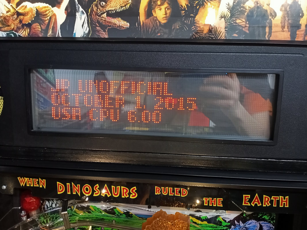
Jurassic Park had several game code updates over the course of its life, reflecting various bugs that Data East was trying to fix. The latest revision of the software is 5.01.
Chad Hendrickson released an updated version of the main game code as well as the display code in 2015. This update makes huge changes to the game, and for the better. The features I like most are the randomised skill shot patterns (he's much harder to hit now!), randomised modes (no more starting with STAMPEDE every game) and removing the "free" tri-ball multiball on the third ball. Plus, there are heaps of bug fixes and updates to scoring to make it more balanced. I used the original ROM chips and reprogrammed them with the new code. A worthwhile upgrade for any Jurassic Park game!
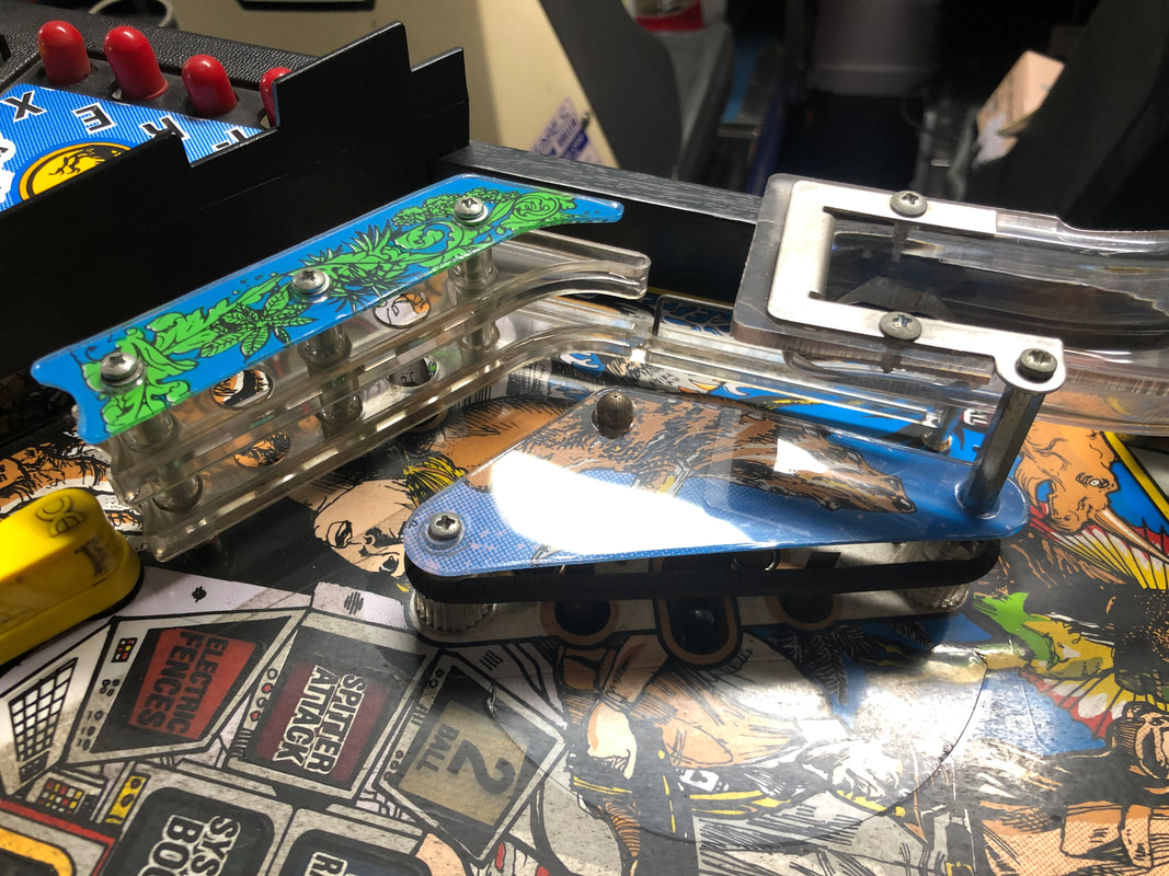
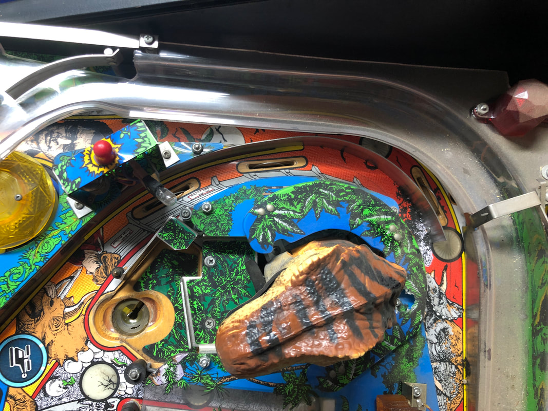
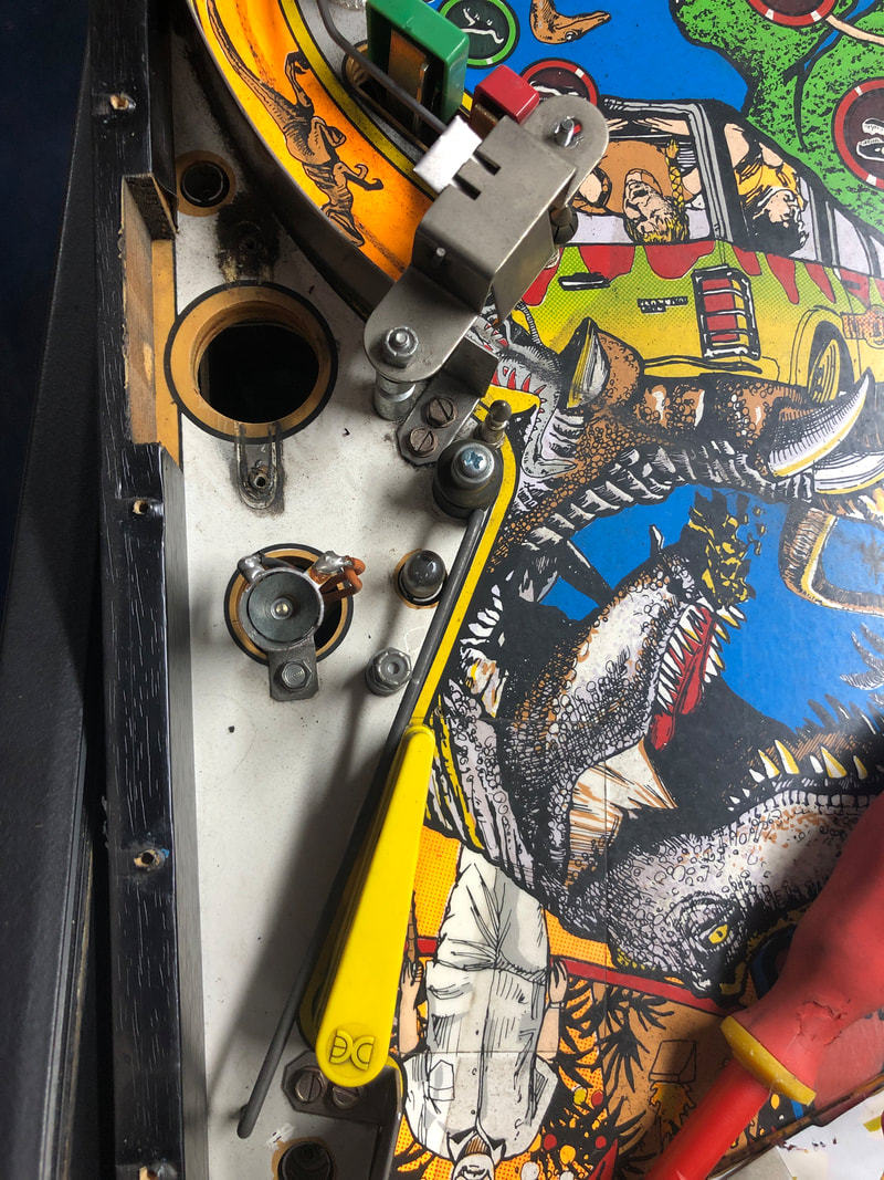
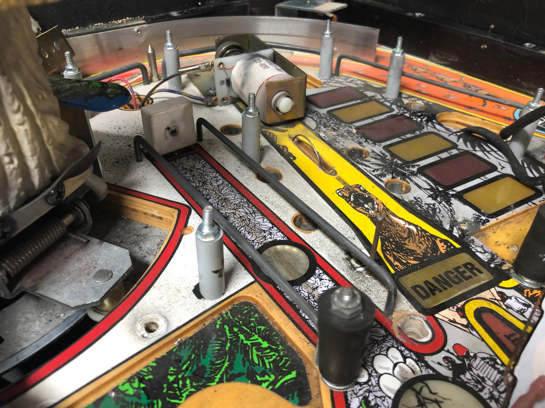
Ramp diverter binding on ramp
I noticed that the ramp diverter was not opening and closing properly because it was binding on the plastic ramp. There were gouges on the ramp from where the diverter had dug into the plastic as it was too close to the ramp.
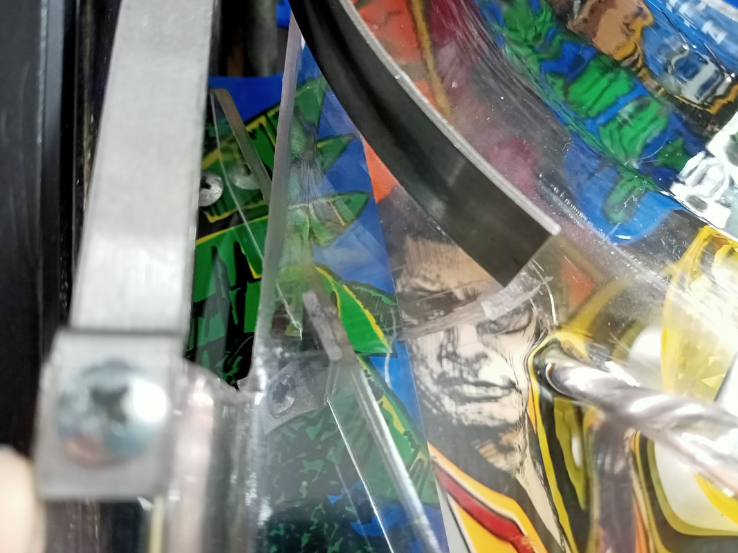
Scratches on the plastic ramp due to a binding diverter.
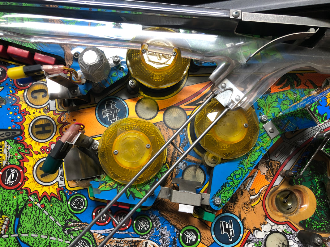
I eliminated any mechanical issues with the diverter itself; it seemed to be totally fine. Instead, one contributor to the problem was the plastic piece mounted directly under this section of the ramp. This clear plastic is designed to stop balls from getting stuck above the left pop bumper area, and when installed it basically sits in contact with the ramp above, propping it up. In my opinion this is a design oversight, as this plastic piece does not need to be this high. Removing the piece did help, however it does serve a purpose and should be kept in place if possible. 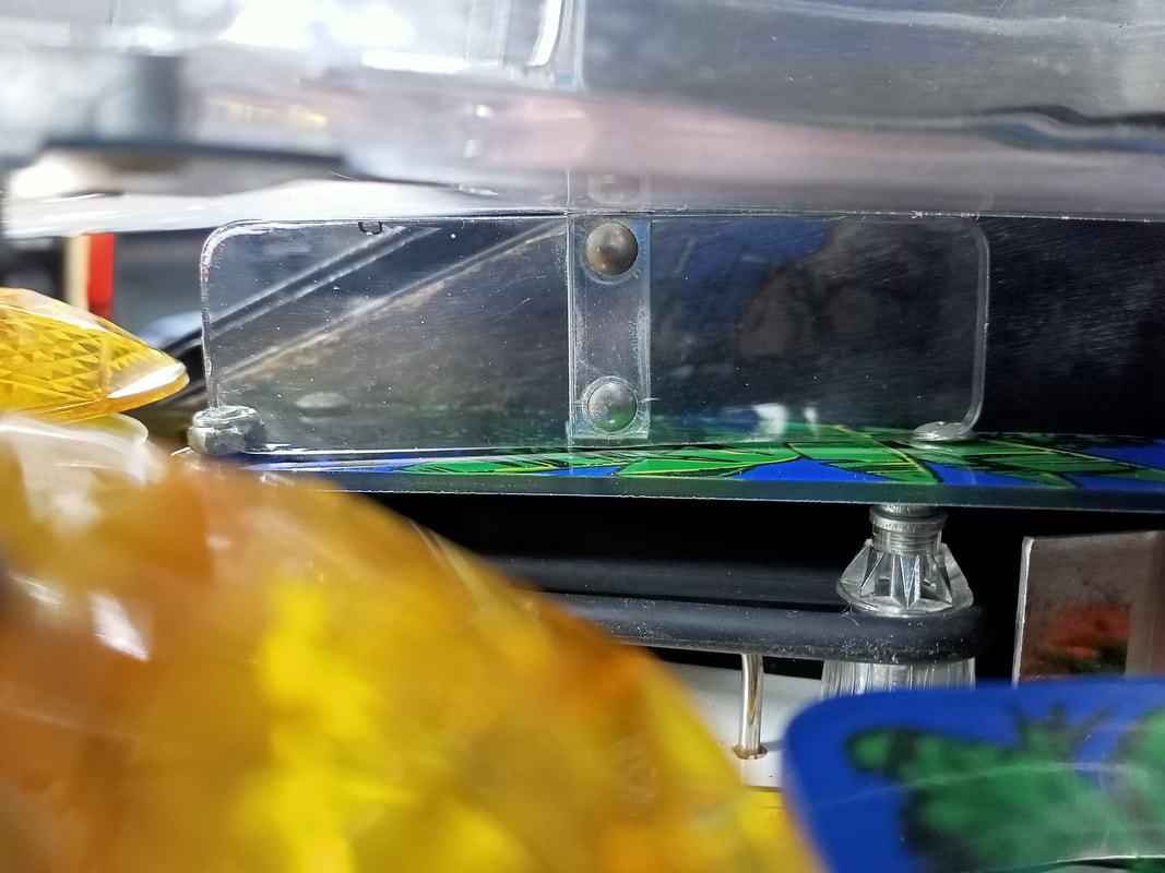
Plastic guard installed under (and in contact with) the ramp above.
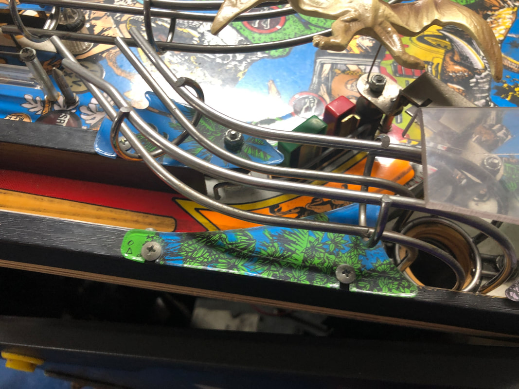
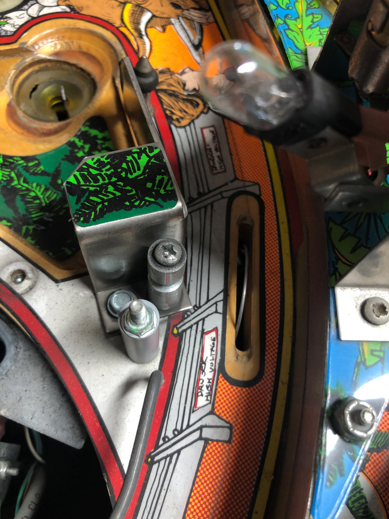
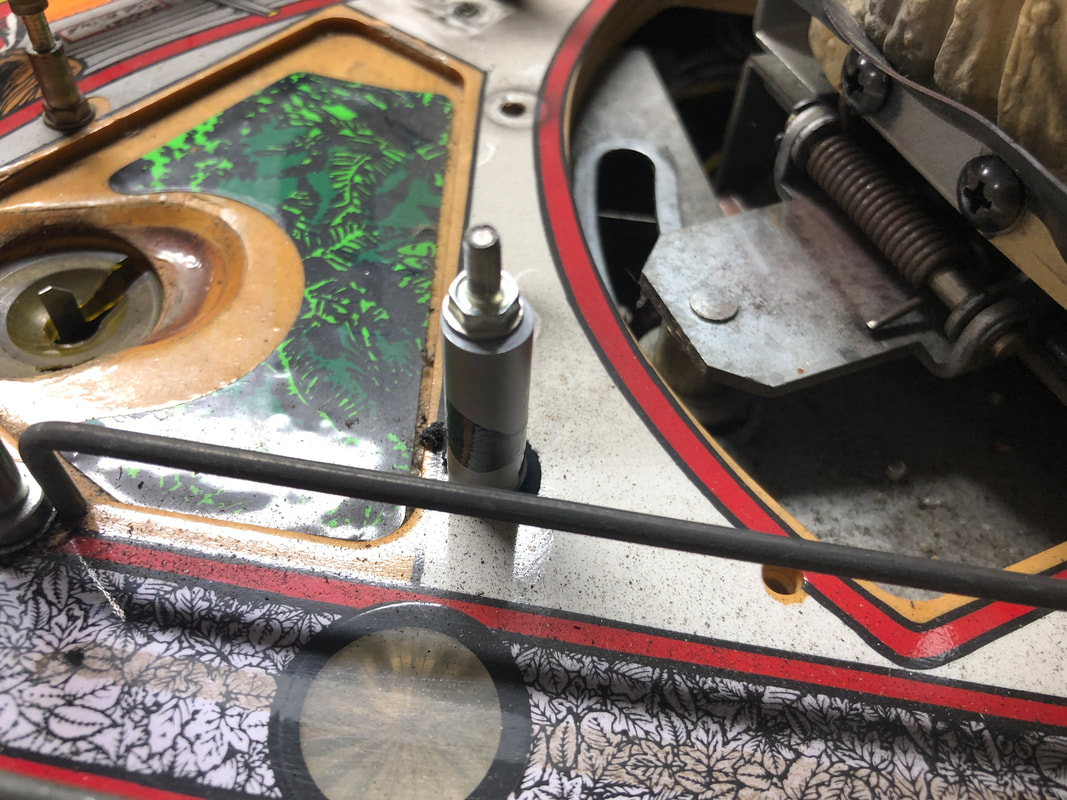
The problem was solved when I realised that I had forgotten to install a part on the playfield. There is a metal post which sits just in front of the diverter shaft. The ramp screws into this post, and the post is secured by a screw through the underside of the playfield. Screwing the ramp into this post forces it downwards slightly, and the post keeps it secure in this position. This downward force is enough to create some additional space under the diverter arm, which allows it to move freely. So don't forget to install this post! 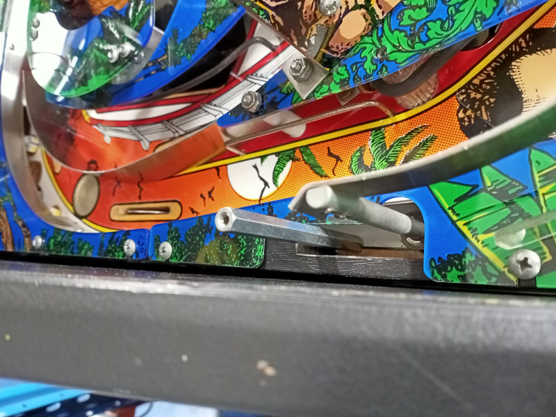
Metal post next to the diverter shaft which secures the plastic ramp.
Miscellaneous minor repairs
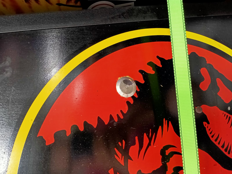
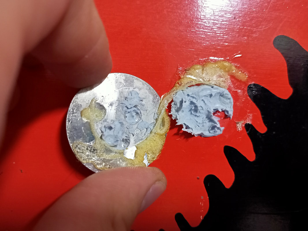
There was an odd "dot" on the right side of the cabinet where someone had stuck a metal "button" onto it. No idea what it was here for. Maybe to protect the cabinet against hitting a wall? It was stuck on with Blu-Tac, and some other nasty glue, which took a lot of rubbing with detergent to finally clean off.
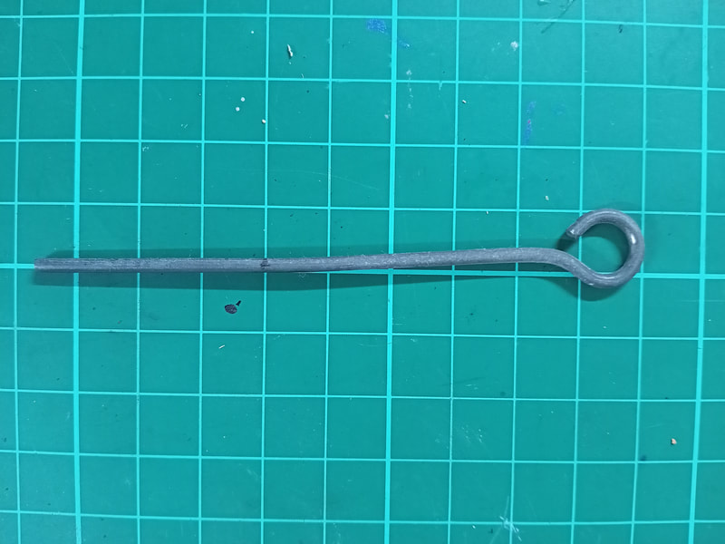
The tilt bob rod was a little bent, which meant that it was much easier to tilt the game to the right side than the left, even when it was perfectly level. A couple of seconds in the vice got the rod straight again.
The Bunker and Control Room scoops cop an absolute beating. They are part of a single scoop assembly, with both scoops connected to one another via a small trough. The Control Room scoop was significantly more bent than the Bunker scoop, and the scoop metal was about 1cm higher and a little further back than the Bunker scoop. I re-bent this scoop in the vice so it was the same shape and size as the Bunker scoop. This would put less stress on the plastic above the Control Room scoop (which was originally broken).
The playfield didn't sit nicely when it was in the fully raised position, and seemed to shake a little when it was being moved. The playfield support bracket on the right side of the cabinet was loose. Two of the nuts were loose, and one nut was missing altogether. Installing the missing nut and tightening everything up fixed the issue.
If you are having problems with the saucer kickout being very weak, check the screw mounting positions under the playfield for the coil assembly, as well as its spring. Service Bulletin 40 indicates early production games had incorrect springs and screws installed in the wrong places. I didn't have these issues on this game however the saucer was cracked, so a new one was ordered and installed (PSPA).
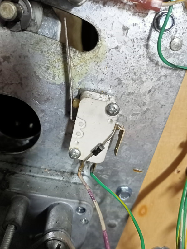
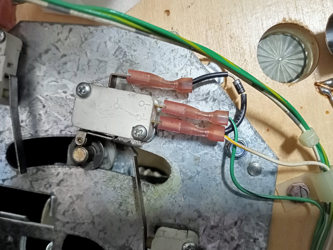
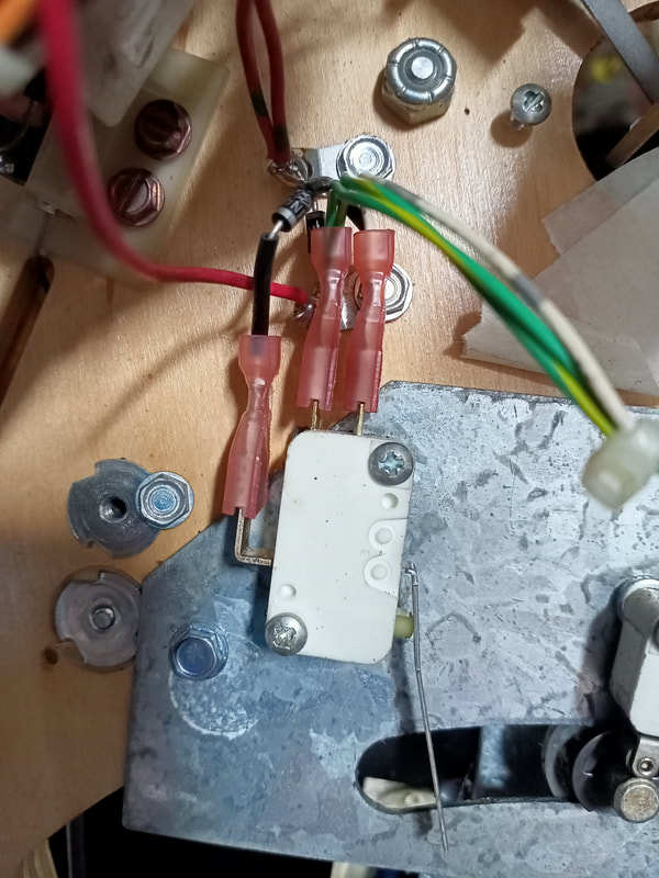
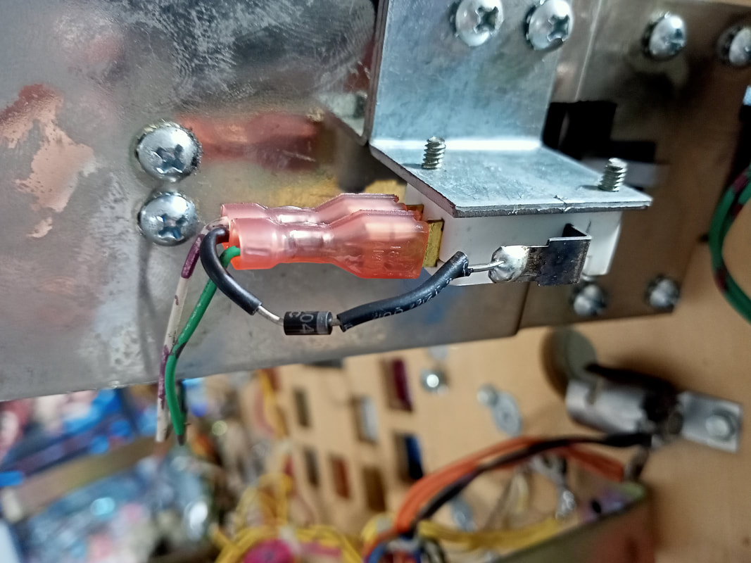
The trough was having some issues serving balls into the shooter lane. Turns out a diode had broken off the switch which detects that a ball has been released from the trough. These switches have lugs with crimp terminals attached to them, but personally I dislike crimp terminals for this purpose. I prefer soldered connections for better reliability, so I soldered the diode back into position.
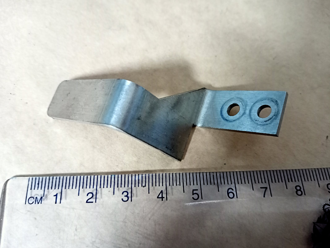
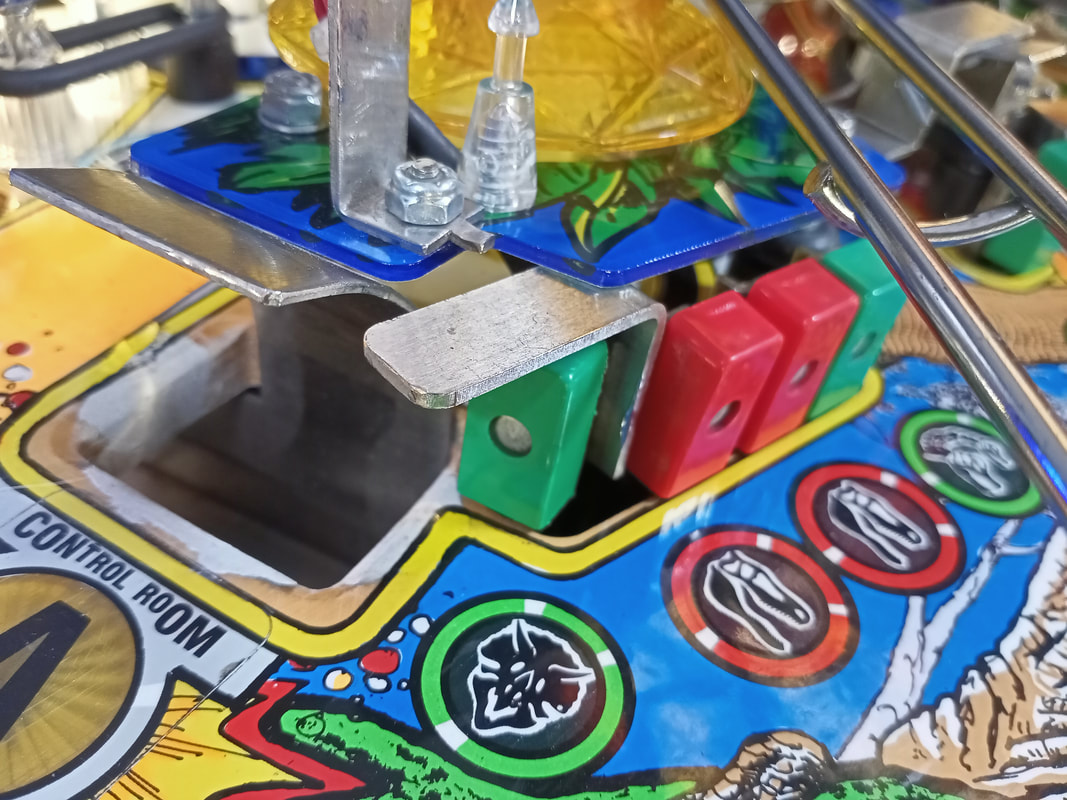
I found a mystery metal piece in the coinbox while cleaning the game and could not for the life of me figure out where it was supposed to go. Turns out it is a ball defector meant to be installed behind the Triceratops target to the right of the Control Room scoop. Balls come at this target at high velocity and the deflector is needed to reduce airballs.
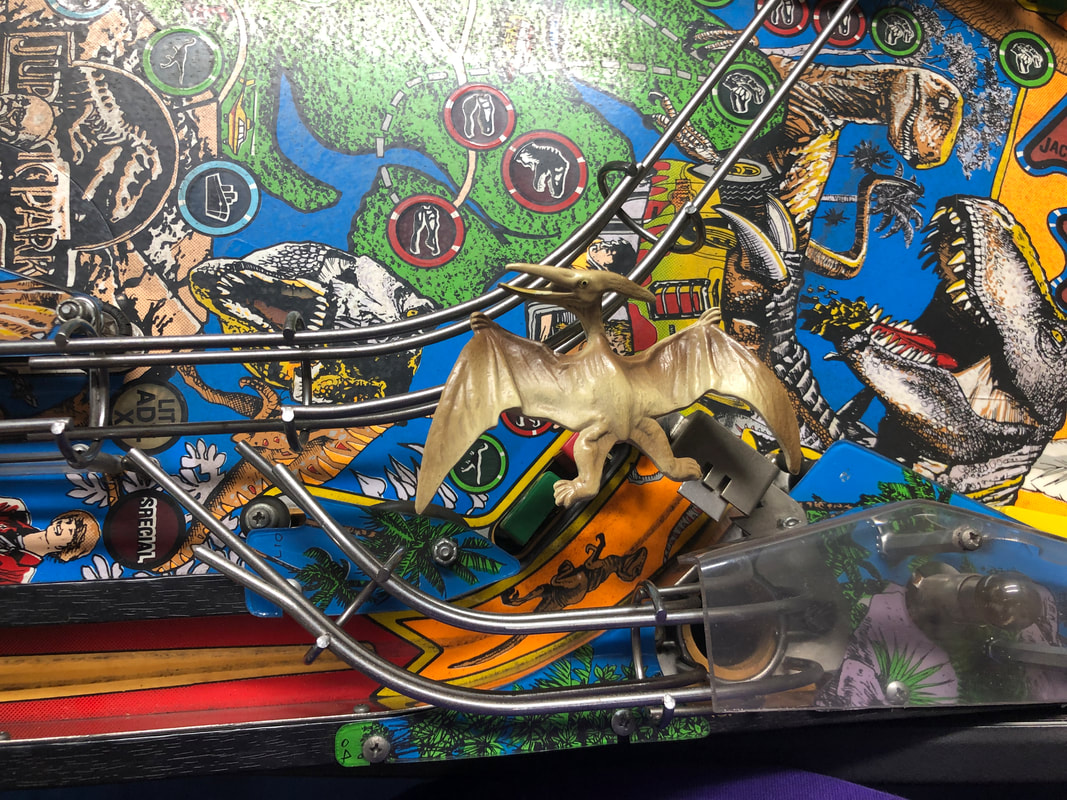
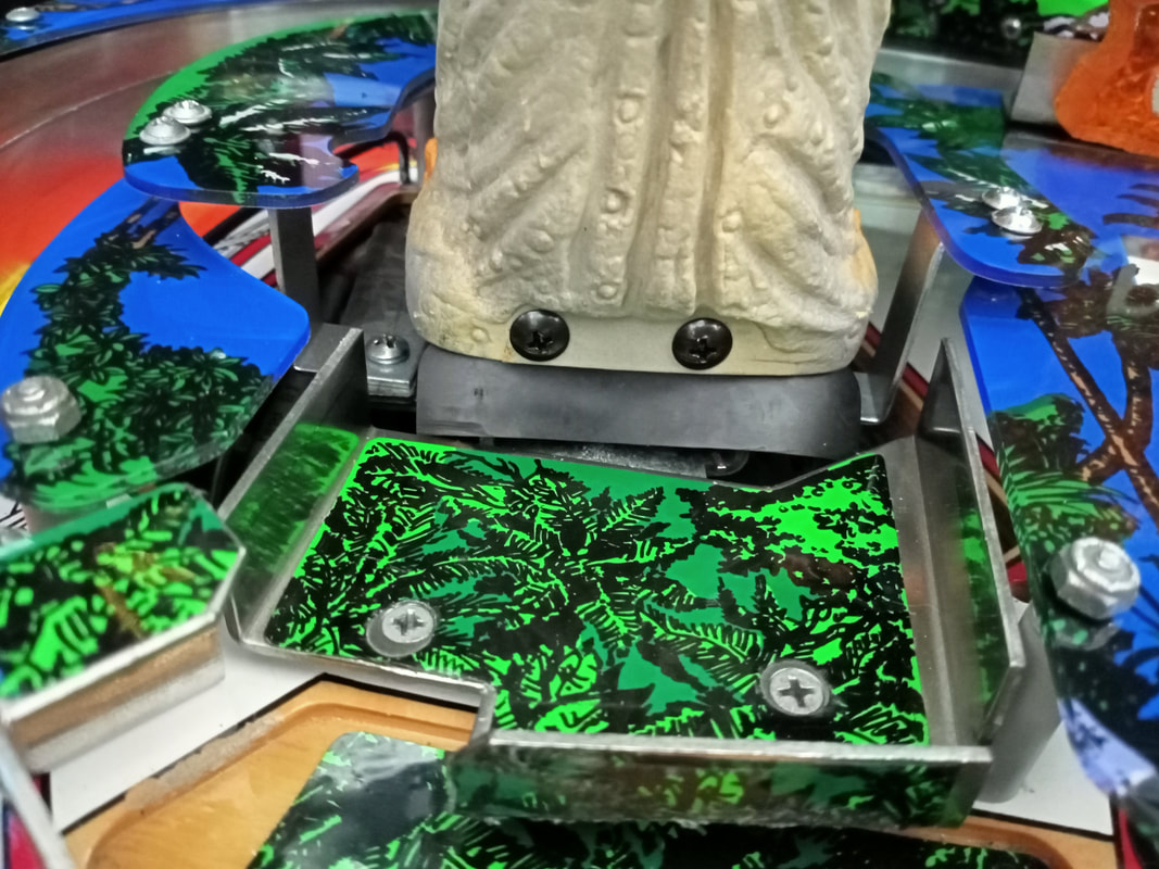
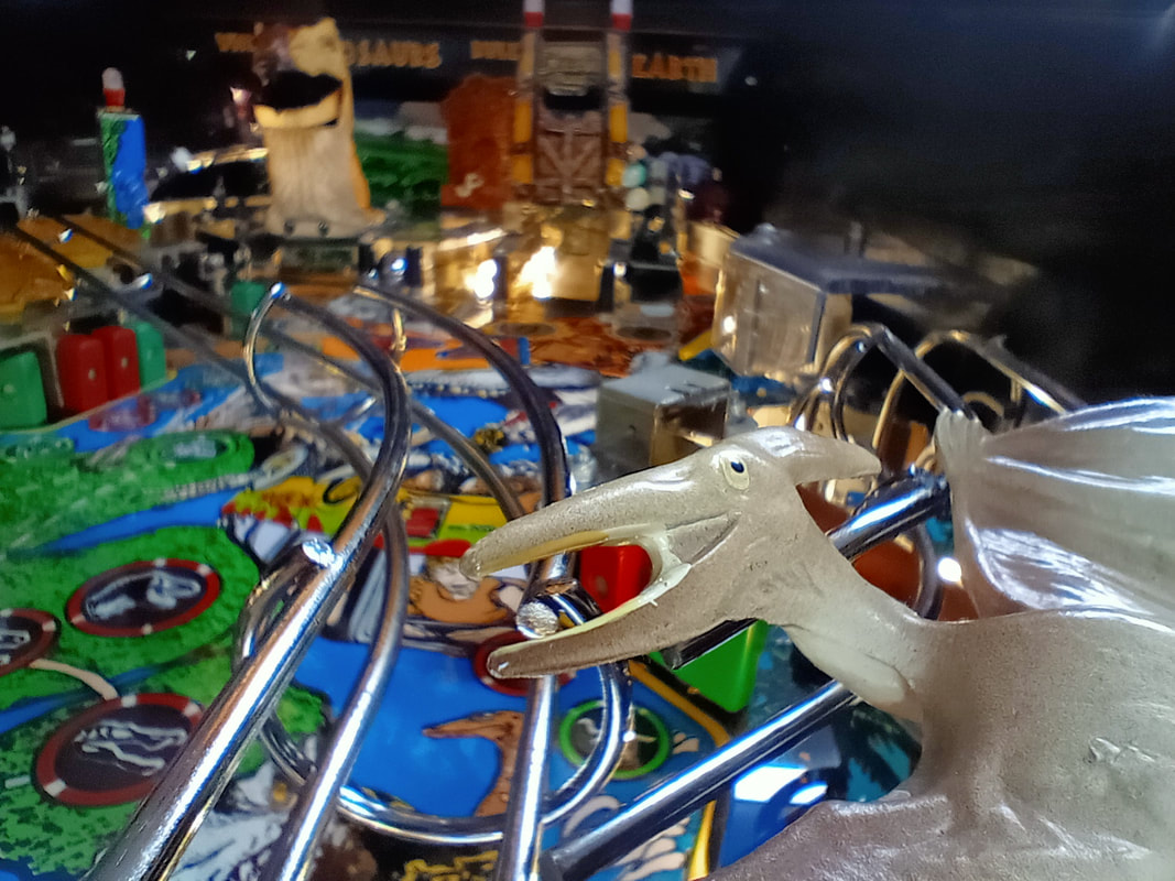
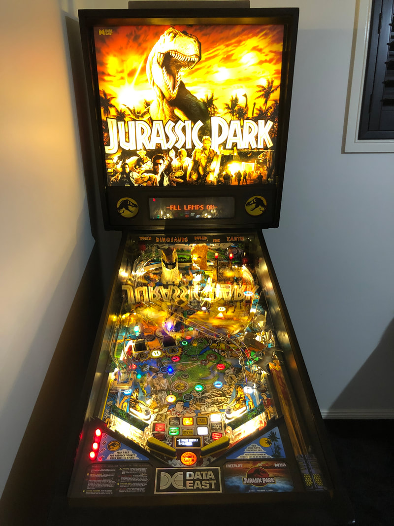
Reassembly The only thing I got mixed up when putting the game back together were the spacers which hold the metal guard in front of the T-Rex. There are two spacers and they are different sizes. These sit under the metal piece in front of T-Rex and hold it at an angle so the ball rolls down into the saucer. So make sure the taller spacer is installed on the right, while the shorter spacer is on the left. You want the ball to roll leftwards and back onto the playfield if it ever ends up here. 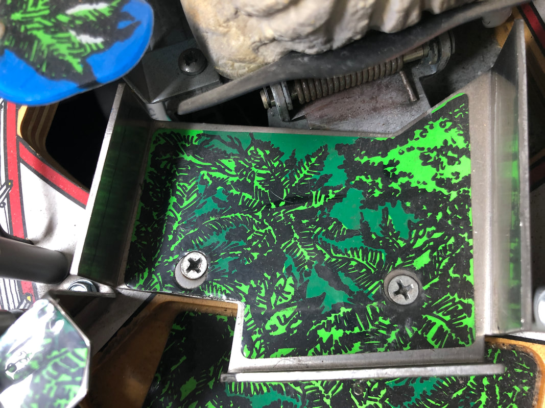 Screws supporting the metal plate in front of T-Rex go through grey plastic spacers. Taller spacer goes on the right. The one-way T-gate which allows the ball into the pop bumper area is frequently broken. Reproduction gates are made by Cliffy and are locally available (RTBB). Thankfully, this one was still in one piece.  T-gate at entry to pop bumpers. The lamps on metal brackets above the Control Room and Bunker scoops need to have their wires routed neatly through the plastics and playfield. In particular, the Bunker lamps are supposed to be routed through a small cut-out to the side of the flasher dome. Route the wires through this hole first before you install the flasher dome, as it is impossible to route the wires properly with the dome installed. 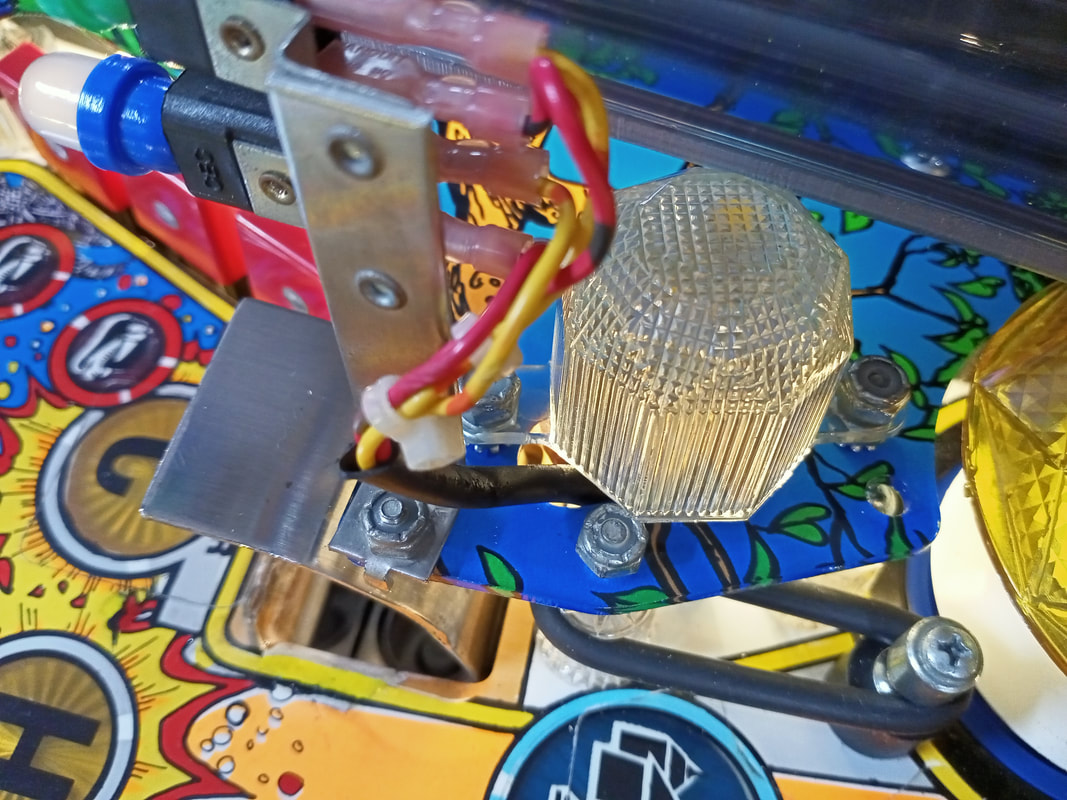 Proper routing of Bunker lamp wires under flasher dome. Another note regarding the Control Room and Bunker. When putting the Control Room and Bunker scoop assembly back together, consider adding some silicone, hot glue, or similar shock-absorbing material to the Control Room switch (the switch in the centre of the scoop trough). This fix was suggested by Service Bulletin 43 due to the diode being subjected to shocks when in contact with the metal trough. There are various custom instruction cards available for Jurassic Park online. I went for a set made by Aurich on Pinside. They look awesome!  Custom instruction and pricing cards by Aurich. There are a ton of mods available for Jurassic Park, from additional dinosaur figurines, trees, covers for the scoop lamps, and so on. I don't really care for many of those mods, and prefer to keep the game original. However, there is one playfield toy which is often overlooked. There are actually supposed to be two Pteranodons on the shooter lane. Most games only have one for some reason. While the original is no longer available, the recommended replacement seems to be the Papo-branded model (Amazon), which is similar in size and much more detailed. Simply use some piano wire or similar support and screw it into the base of the figurine similarly to how the original figurines were mounted. Then, the other end of the wire can be mounted on any post or threaded screw on the playfield. While this game did not have a topper, reproduction toppers are also available (Ministry of Pinball). Great news, as it is rare for reproduction toppers to be available which so closely resemble the originals. Conclusion This has turned out to be my longest and most detailed restoration log to date, which reflects the multiple months I ended up spending on this machine. I took some extra time to make the machine look nice by painting the legs and lockdown bar, touching up the cabinet, and touching up the playfield. Small things like that come together and make the machine look fantastic. I installed warm white LEDs throughout the playfield and backbox, and the game looks so much brighter and nicer as a result. There are a lot of different colours on Jurassic Park, and this game benefits from some LEDs which throw out a little more light than original incandescent lamps. Of course, black rubber rings look better than white on Jurassic Park, and so the entire machine was rubbered in black. I ordered one special item that I think worked really well for this game; a Jurassic Park keychain for the machine keys! The CPR plastic set does come with a plastic one, however there are a number of enamel keychains available online (Ali Express) which look even better in my opinion. 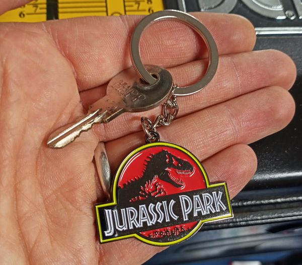 Jurassic Park enamel keychain. Jurassic Park is a fun game, especially with the updated game code. The ramp is a nice, flowy shot, and hitting it for successive combos is really fun. I applied a couple of coats of wax to the playfield and it plays incredibly fast. So fast, in fact, that balls shot up the ramp will pick up so much speed that they fly past the diverter and sometimes fall off the wireform ramp! It really adds to the chaos, especially during multiball when the balls are flying around so fast that you can barely see them. While it was a long haul restoration I was proud of the final result and I hope the owner will be just as happy with it! Below are some images of the finished machine, as well as a short video of gameplay.
4 Comments
Matthew Svabik
7/12/2022 04:46:02 pm
Hello. I have one of these machines that is not in working order. Powers up and that’s about it. It’s priceless to me as it was given to me by my grandfather who is no longer with us. I’ve scoured the internet to find someone with your knowledge and this full on write up was jaw dropping. I’m in south east Michigan. I have no clue who to turn to in order to do a restoration or repair on the machine and wonder
Chris Ryan
2/12/2023 07:44:15 am
Did you ever figure that out? There is a place in Ann Arbor that does repairs. Leave a Reply. |
About
Here you will find logs of our pinball and arcade machine restorations, repairs, discussion about general pinball and arcade topics, as well as recounts of our random pinball adventures.
Check back regularly for updates! Blog updates
Archives
May 2024
Categories
All
Donate

Running this website is a hobby for me (just like pinball!). I like being able to show off my restoration work so everyone can learn from it and potentially fix their own machines. If you enjoy reading the site's content or it has been helpful to you, please consider donating to offset some of the website's operating costs. |


 RSS Feed