- Published on
Leisure & Allied Industries "Skill Tester" (Type 1)
- Author
-
-

- Name
- Posts
- Posts
-


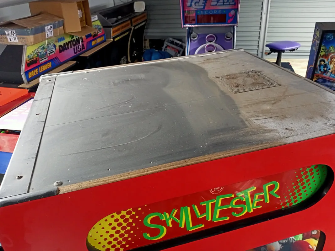
Normally I start each blog entry with an image of the flyer for the game I'm going to be working on. Unfortunately, Leisure & Allied Industries (LAI) produced very few flyers for their games, particularly the simpler redemption games. However, there are few games that were as ubiquitous in Australian arcades as the classic skill tester claw machine by LAI. This particular example was one of the cabinets from our container-of-games pickup several years ago, and it was basically in working condition when I got it. However, it had never had a proper clean, and a few small issues were starting to appear, so it was time to give this machine a good going-over.
- Timber cabinet in good condition.
- Neon marquee working, but missing some screw supports.
- Castor wheels intact and rolling nicely.
- Playfield (prize bed) quite dusty and grimy but no significant damage.
- Claw mechanism working, but occasionally binding and had sluggish movement.
- Main control board in good condition.
- Power cord in poor condition with visible damage.
- One fluorescent lamp in head not working.
- Game powered on and could start a game.
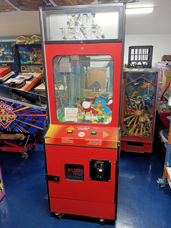
A description of the differences between LAI skill testers is warranted here. This skill tester was manufactured by LAI around 1985 and is known as a "two-button" skill tester due to the two-button control panel. LAI made various models of skill testers, with the two-button and the joystick control versions being the most recognisable. Cabinets with a joystick controller, released after the two-button version, were often referred to as the "pink" LAI skill testers due to them commonly having bright pink cabinet livery.
I refer to this machine as a "Type 1" machine because there are actually two versions of the two-button skill tester. They are almost identical in terms of their physical appearance and cabinet build. But the Type 1 machine is a little lower-tech. The table below summarises the differences as I observed them.
|
Feature |
Type 1 Skill Tester |
Type 2 Skill Tester |
|
Control system |
Relay and switch driven |
Microprocessor controlled |
|
Playfield access |
Pull-out timber door panel |
Hinged aluminium door |
|
Sound effects and music |
No (unless upgrade board is installed) |
Yes, volume adjustable by potentiometer |
|
Claw strength |
Adjustable by potentiometer |
Adjustable by potentiometer |
|
Motor speed |
Adjustable by rheostat |
Adjustable by potentiometer |
|
Prize dispensing detection |
None |
Yes; plays sound effects on prize dispensing |
|
Control board access |
Screwed to cabinet wall |
Sliding pull-out tray |
|
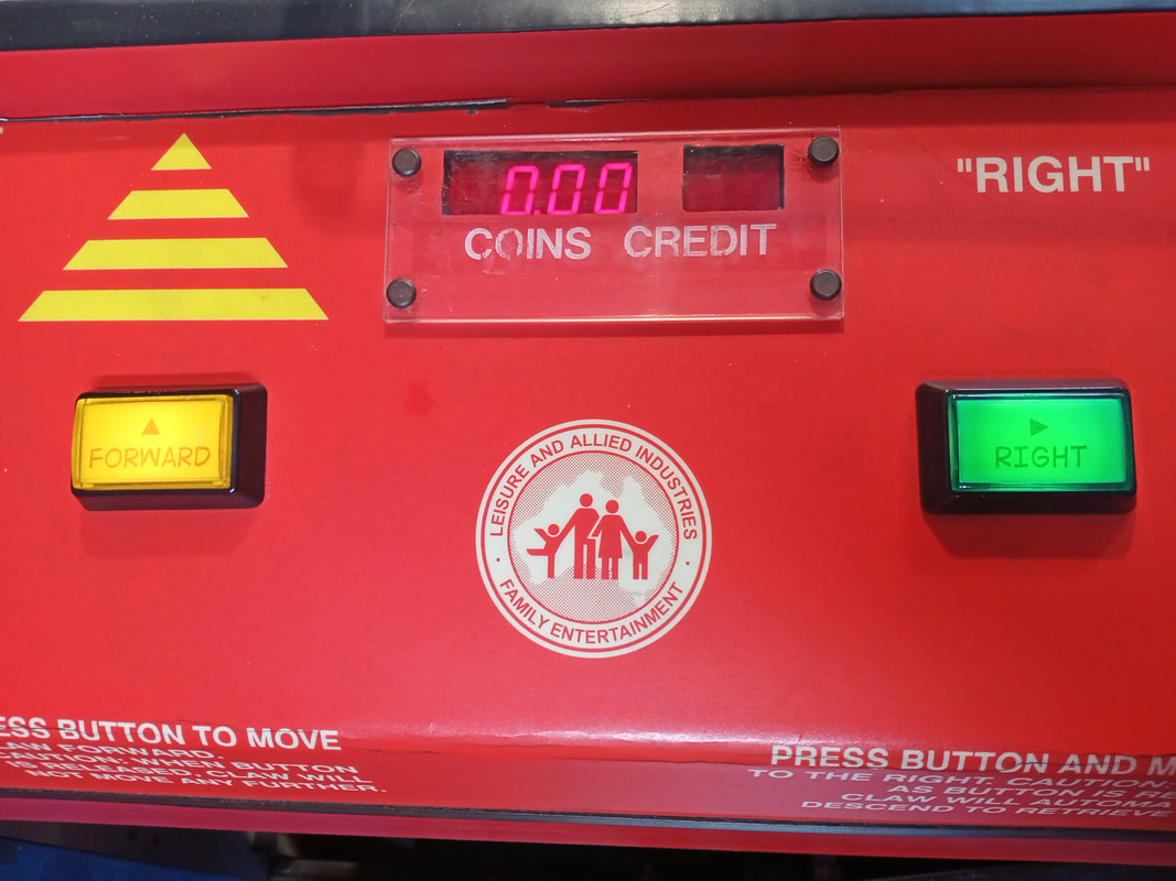
Credit display |
On control panel |
On playfield |
|
Cabinet head access |
Through front marquee |
Lift-out door panel on top |
There is limited information online about these games, and their manuals are not available in any reasonable resolution online. So, I'm intending this blog post to serve as a general technical resource for these skill testers to assist others in repairing and maintaining them. I've compiled a bunch of information here from many different places, and have gone out of my way to explain the theory of operation for each part of the machine as best I can. If any of this information helps you repair your own machine, please let me know, as I'll be glad to see people keeping this vintage machines alive!
Disassembly
Working on the control board, lamp ballasts, and transformers is tricky, because they are installed to the side of, and below, the prize return chute. To properly inspect and clean these components, I had to remove the chute. This can be done by removing several screws including two wood screws that secure the chute to the left side of the cabinet, two nuts and bolts and two wood screws that secure it to the prize bed above, and one nut and bolt that secure it to the rear panel. Note that a ground strap is also connected to the nut on the rear side of the panel. Once those screws and bolts are removed, the chute can be wiggled forward and downwards so that it can be removed through the coin door. I found it helpful to remove the ballast below the chute, as well as the starters, so the chute had move room to move in the small space. The coin box and coin box enclosure can also be removed for ease of servicing (four wood screws each). The rest of the machine is fairly easy to access and service. The topper area behind the marquee can be a bit fiddly; see that section for specific details.
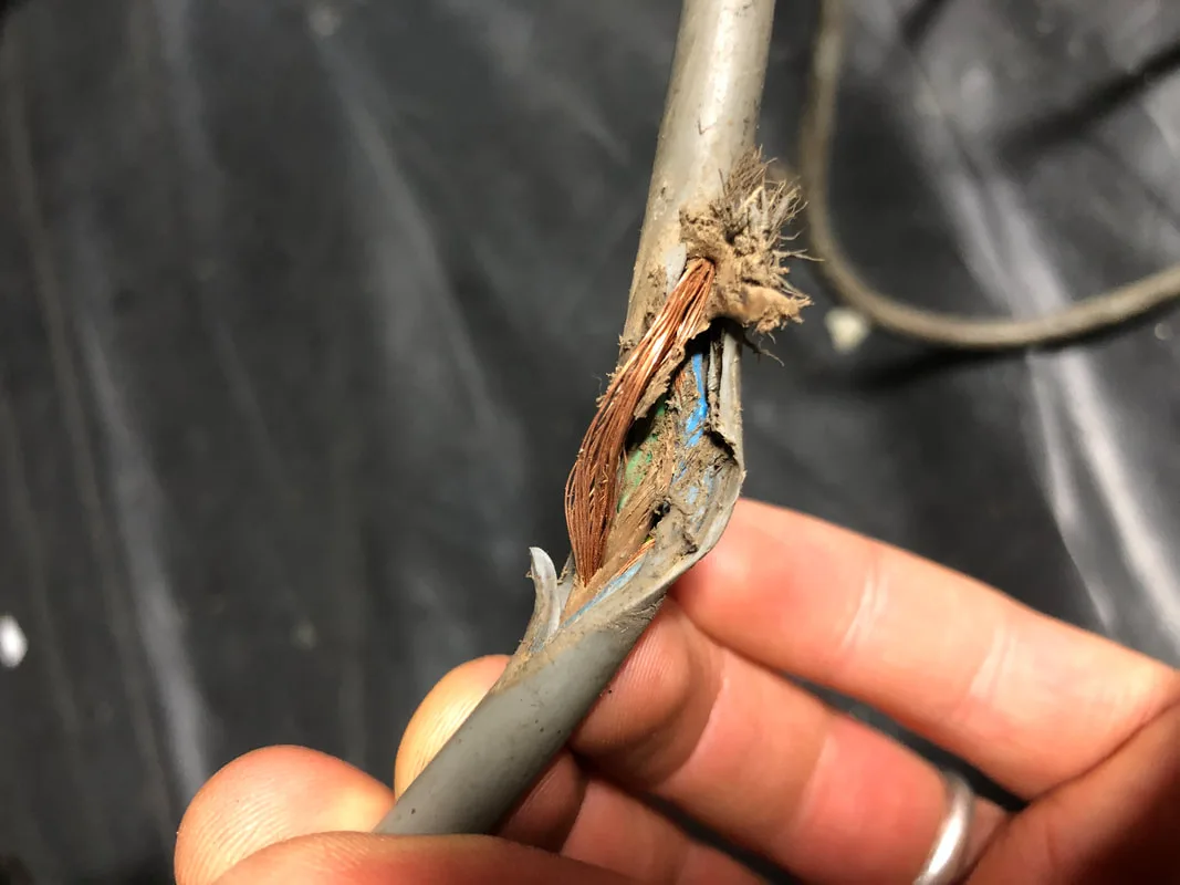
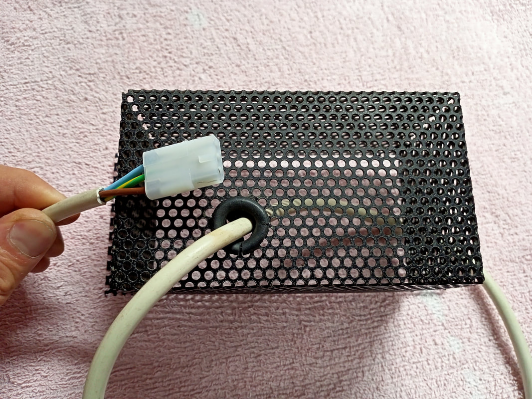
Power cord damage.


New cord and connector installed.
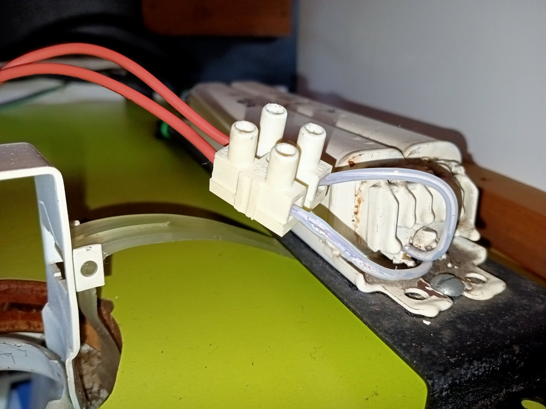
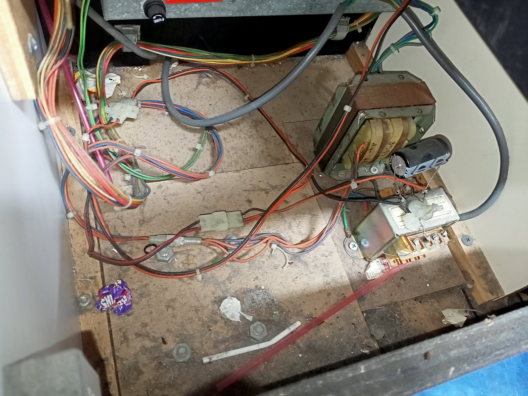
From the distribution box, power goes to a few locations. There are two transformers at the bottom of the cabinet which are fed from here. The larger transformer supplies 24 volts for the relays, as well as 48 volts for the motors and claw solenoid. The smaller transformer has a bridge rectifier and capacitor attached to it, and supplies rectified, smoothed 12 VDC to the credit board, coin mechanism, and the main control board (where it is fed to the lamps and switches on the control panel).
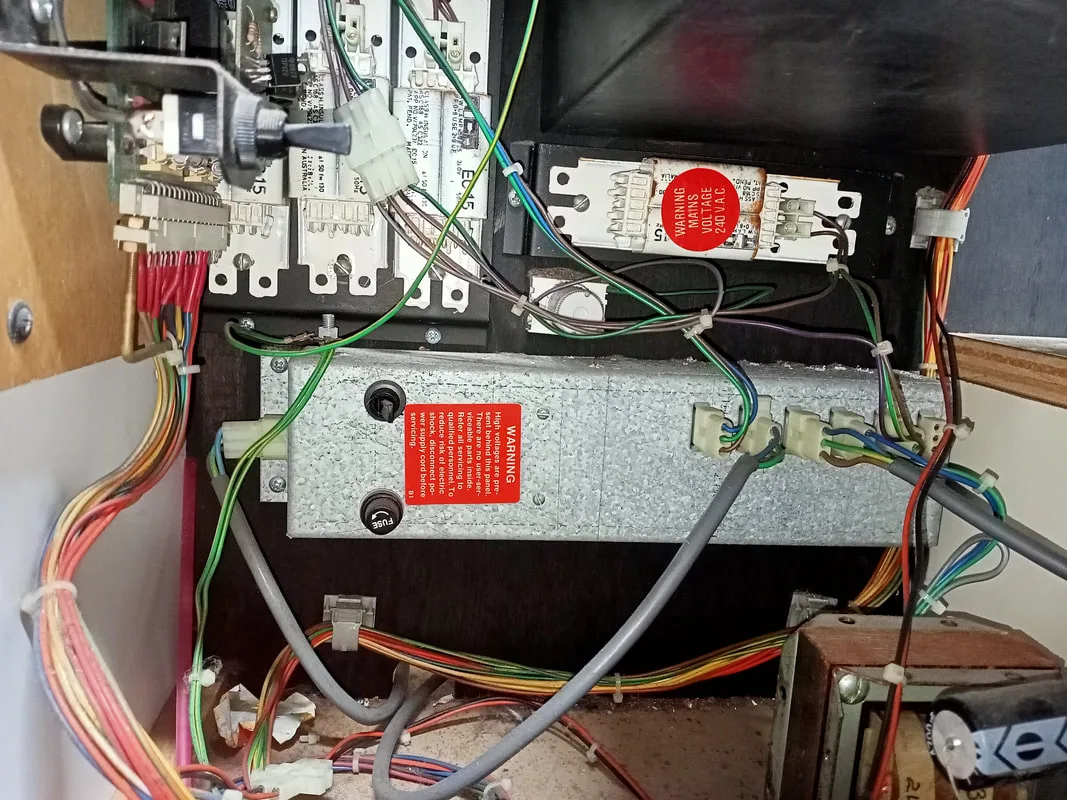
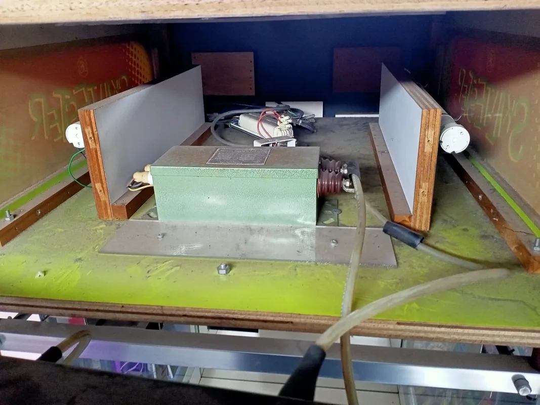
Power distribution box. Line in at left. Loads plugged in at right.

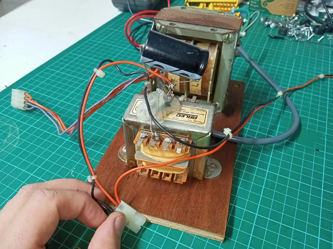
Transformer panel removed from cabinet.
The system is relay driven, with no microprocessor controls required (apart from those that drive the LEDs in the control panel and any credit boards for coinage). Three large relays are the main feature on the control board, with each assigned to drive a specific motor. Even the original coinage system is driven by two small relays on the control board, with a switch to control pricing settings. Other functions are transistor-driven, such as the claw solenoid. The strength of the claw is adjustable using a potentiometer on the control board, which can be altered to suit the types of prizes being vended. The claw is relatively weak at the best of times, so I set it to its maximum strength. The rheostat to the side of the control board adjusts the speed of the motors. It can be adjusted from about 38 to 500 ohm. Higher resistance results in slower motors. I found that keeping the terminals closer together (less resistance) for a faster motor speed was best. The control board on this game has part number "EAV85-5" silkscreened onto it, and has various jumper wires and cut traces on it. After seeing some photos of other peoples' machines, I've come to realise that most of these wiring modifications were done at the factory, and were not operator hacks done in the field.
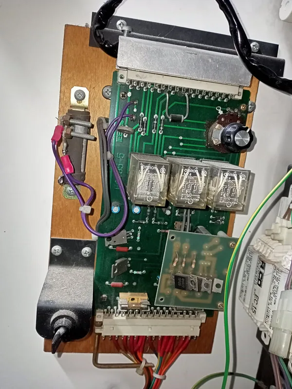
Control board panel, front side.

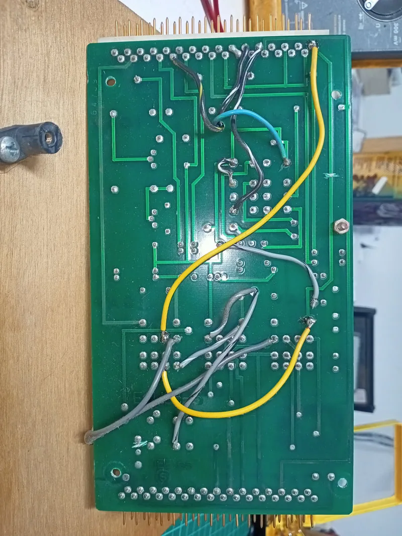
Control board, rear side.

Nigel at Sunrise Micro actually developed an upgraded control board for these skill testers which incorporated sound effects, timing controls, more precise claw controls, and electrical reliability improvements. As many arcade games in Australia utilised Nigel's universal credit boards (this one contained a Mk4a credit board), he also released a technical bulletin with instructions on how to upgrade original skill tester control boards with diodes so that voltage spikes from the crane and motors would not interfere with the credit board. I actually reached out to Nigel because the layout of my control board was different to the photographs on his website. He advised that the diode upgrades are not necessary on my revision of the board. Still, it's cool that you can email the developer of a part some 30 years after the part was made and still get technical support for it!
Luckily, everything on this board appeared to be working well so there was no need to perform any repairs. Documentation on this board is very limited, so if any of the machine's motors stop working, the first step is to check all switches for correct operation. Then, swap relays around and note if problems follow the relay or not. There is some documentation in the form of hand drawn wiring diagrams and theories of operation in the following threads on Aussie Arcade:
While doing some research into this model of skill tester I began to draw some interesting parallels to other claw machines made by other manufacturers. The two-button configuration appears to be a copy of several crane designs from the US, These cranes seem to have an almost identical control board and claw mechanism in them, which leads me to think that the designs were simply copied by LAI. They were potentially used under licence, but I can't find any information to substantiate that. The similar cranes include "Big "Choice" and "Action Claw" machines made by Betson. Most of the troubleshooting advice and indeed the documentation relating to any of these machines is actually applicable to all of them, as they are very similar mechanically and electronically. You can theoretically transfer parts between manufacturers' machines with little modification, too. In particular, I found the below video extremely helpful in explaining the theory of operation of most of the game's parts, and highly recommend giving it a view.
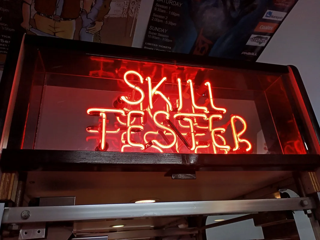
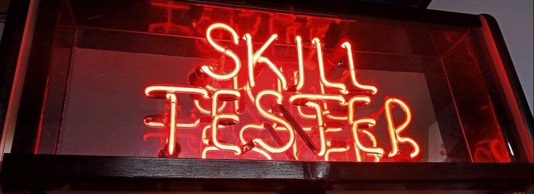
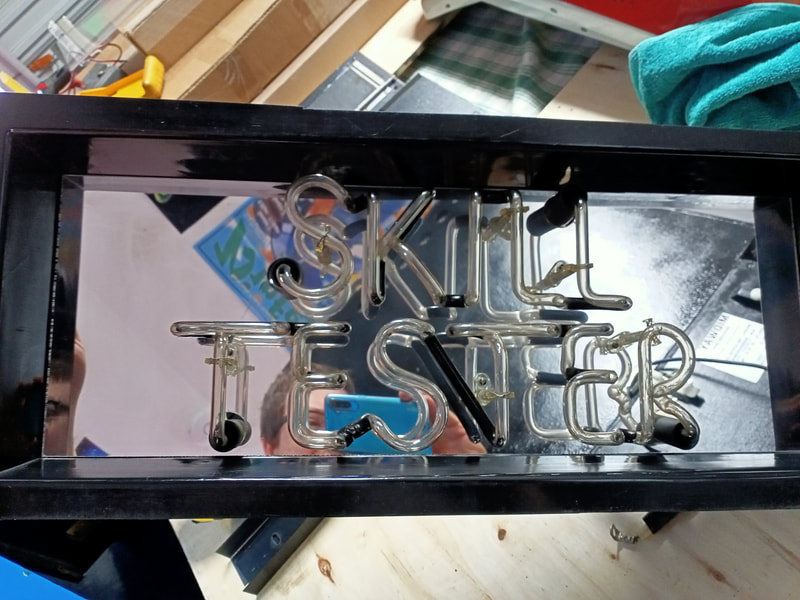
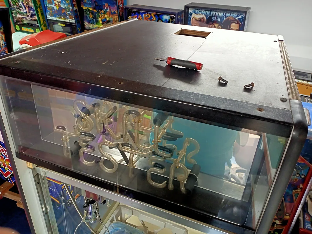
Skill Tester neon lit up in all its glory!

Skill Tester neon sign, removed from cabinet.
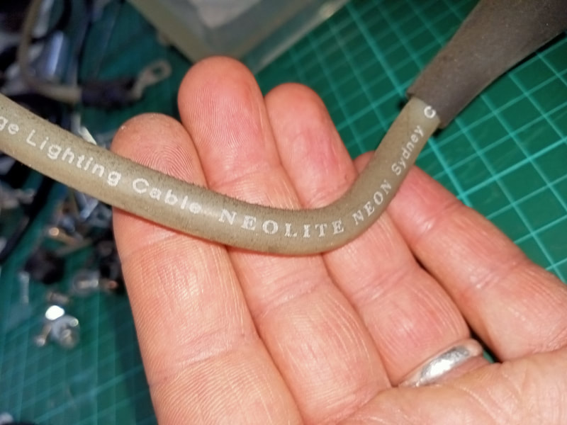
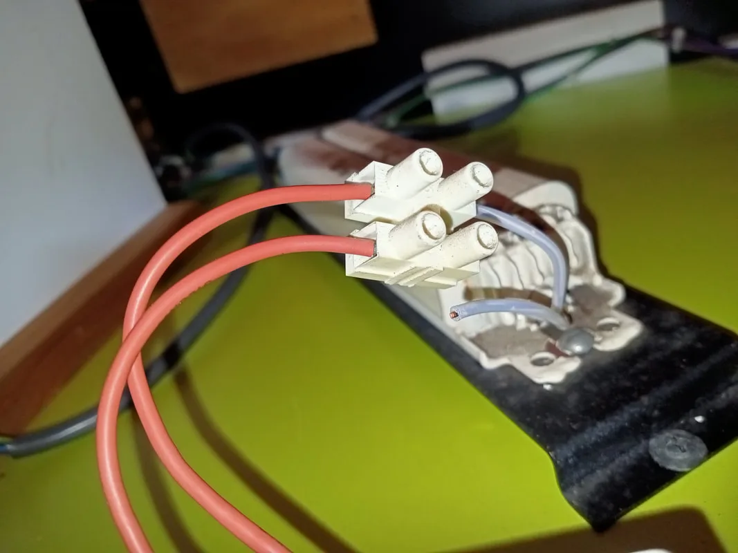
Be careful when removing the neon tube from the cabinet; it's tricky. It helps to have three sets of hands for this, as you need to remove the metal brackets at the top and bottom of the plastic housing, and then pull the neon forwards and unbolt it from its transformer in order to remove it. Don't yank too hard on it, or you'll break the supply cables or the glass. I noticed that the cable insulation had the name of a company, Neolite, on it. This is a neon sign company based in St. Peters, and is still in operation today. I sent them an inquiry to see if they had any documentation or other information about working for LAI or on this particular machine. Unfortunately, they had no records from that time period, and couldn't confirm whether they manufactured the neon tubes or just the supply cabling. Still, cool to know that the same company is still doing business some 40 years on! Out of interest, I also asked for a quote to reproduce the neon sign. This will run you around $1,140, so take extra care not to break your neon if you still have an original!

Neolite Neon Sydney is still doing business some 40 years after this cable was installed!
I gave the neon sign a good clean including the glass tubes, mirror background, and plastic surround. It's hard to clean the mirrored surface under the glass tubes, and I didn't want to risk breaking it by forcing a cloth into the tight spots. I noticed a couple of mounting screws missing. I replaced these so the glass tubes were more secure.
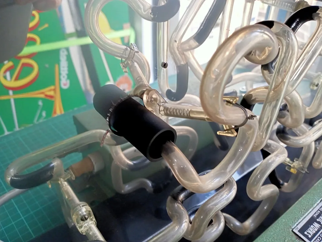
Missing screw and loose mounting bracket for the glass tube.
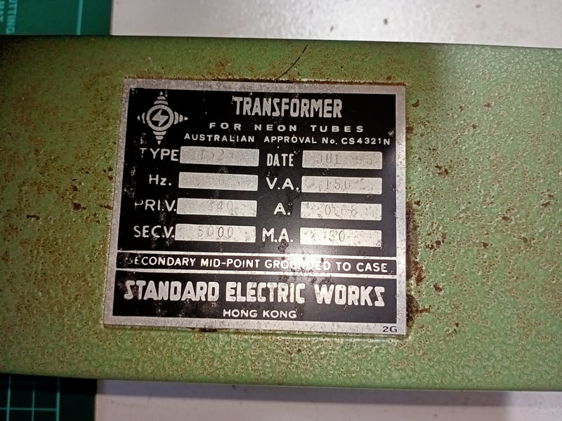
Otherwise the sign was in good working condition, so I set it aside while I worked on the rest of the lights. I noted that in my cabinet, the active and neutral (brown and blue) wires that fed the neon transformer were reversed (i.e. brown connected to blue and vice versa). The transformer takes an AC input so this doesn't really matter. In case you ever need to replace the transformer for the neon, here are the specifications.

Neon marquee transformer specifications.
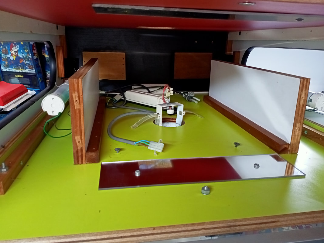
What else is in the head? A single downlight illuminates the prize bed, supplied by a ballast which is also located in the head of the cabinet. This downlight wasn't working, but I pretty quickly traced the problem to a broken wire between the light fixture and the ballast. Stripped and reinstalled the wire into the screw terminal and it was working again.
Broken wire leading to the downlight.
Repaired and working again.
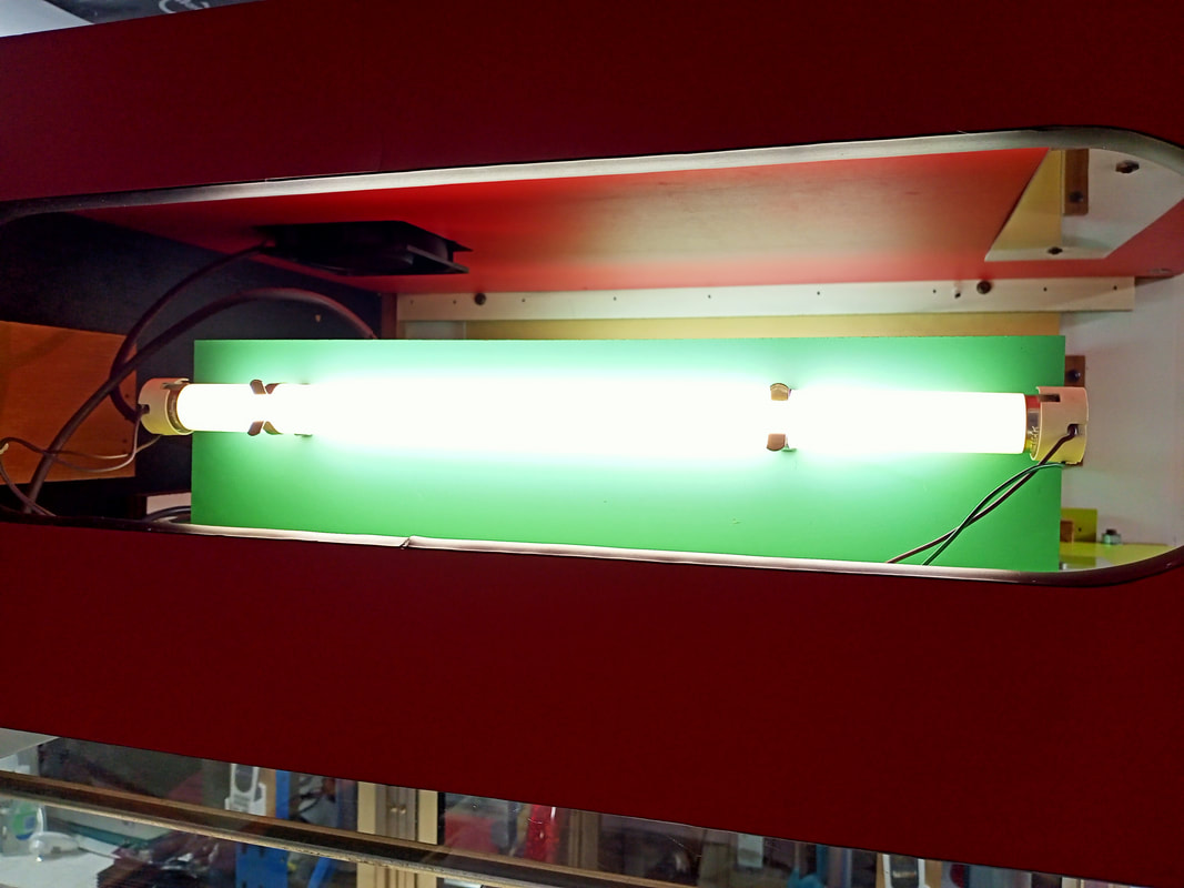
There are also two fluorescent lamps in the head of the cabinet, which illuminate the marquees on each side. To power these lamps are two ballasts and starters in the bottom of the cabinet, driven by 240 volts from the power supply (seems a bit weird to have them so far from the lap fixtures, but okay).
There are actually four ballasts in the bottom of the cabinet, but only two are used. The other two are for additional fluorescent lamps that light up the front marquee if the neon sign is not in use. If your game doesn't have these additional lamps, you can leave the spare ballasts unplugged. Wiring for the additional fluorescent lamps is kept in a bundle in the cabinet head, for future connection to light fixtures if necessary.
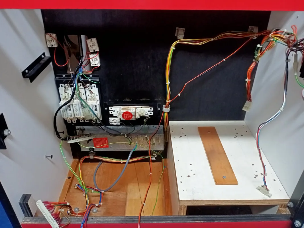
Cabinet base, showing fluorescent tube ballasts and starter sockets (at left).
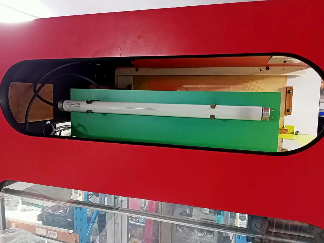
Non working fluoro tube.


We have light!
The power supply also feeds a single 240-volt rotary fan in the top of the cabinet to cool the marquee section (it gets hot in there with all of those lamps!). Several devices in the cabinet head are daisy-chained, such that a single connector at the power supply feeds multiple items. The downlight ballast, rotary fan, and neon transformer are all fed by a single 240-volt supply cable.
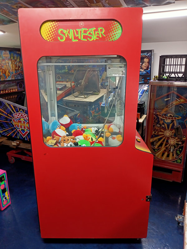
Apart from the electronics, there are also two marquee plastics which are illuminated by the fluoro tubes. They are sandwiched between two sheets of polycarbonate, and slide into position from the front side of the cabinet. The problem with these marquees is that they are printed on very thing, Translite-like material. After years of UV exposure from the fluorescent light, they become fragile. Handling and cleaning them is like handling sheets of thin glass, and bending them too much will cause them to snap. Like this...

Broken skill tester marquee.
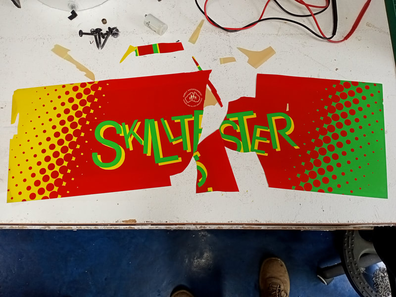
Luckily, I still had one good one. So, I decided to use it to recreate another and replace the one I broke. I scanned it in at 300 dpi in two parts. I merged the halves together in Photoshop. This is quite easy as the letters in the centre of the marquee provide good linear shapes to make alignment easy. Then, I did some minor touch-ups. I selected the green, yellow and red sections with the magic wand/quick select tools and created new fill layers for each. Then, I filled these with basic red, green and yellow colours. This made them pop and covered up minor blemishes and specks of dust. I also filled in the green and yellow in the "Skilltester" lettering so it matched. I had to do some manual touching up of the LAI logo as it was difficult to select with the magic wand (too small). The final result looked pretty good.

New reproduction marquee.
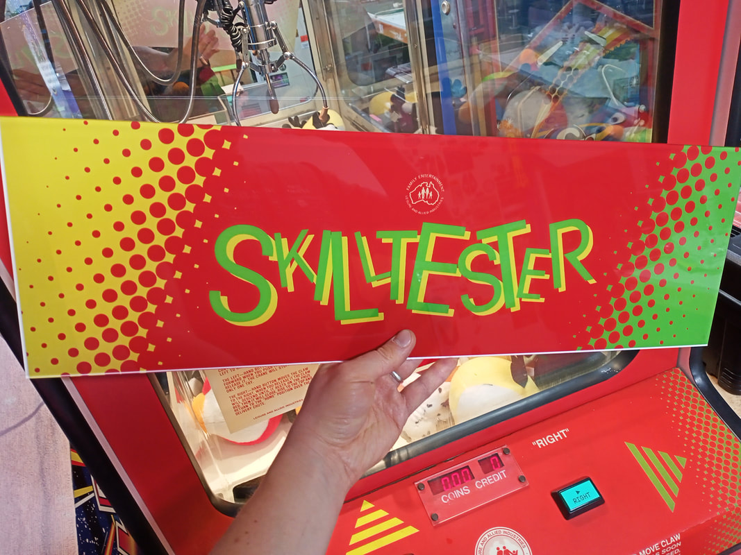

New marquee installed and backlit.


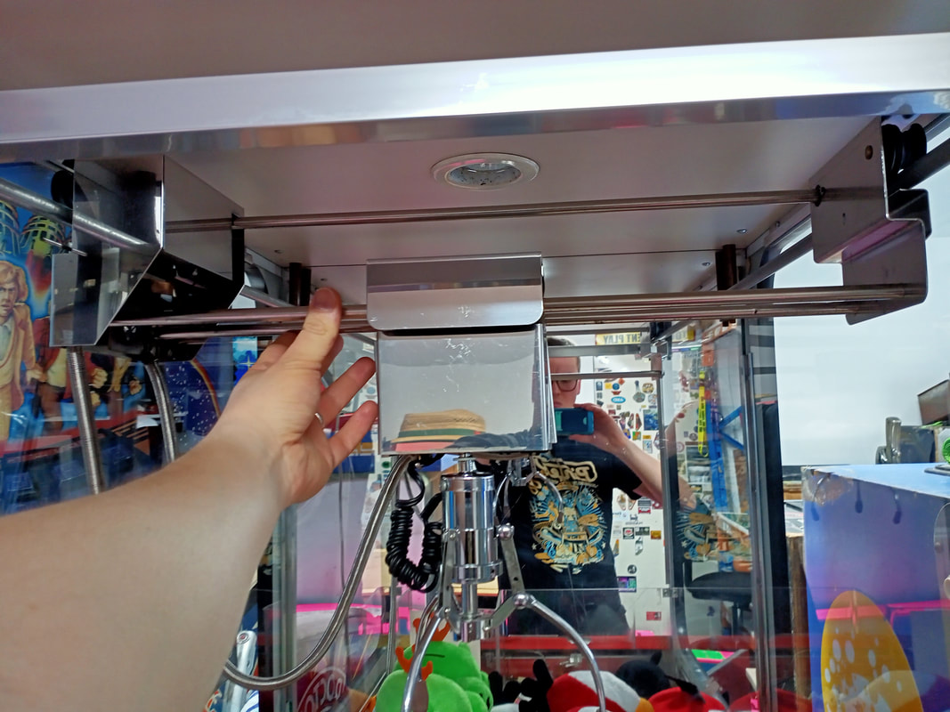
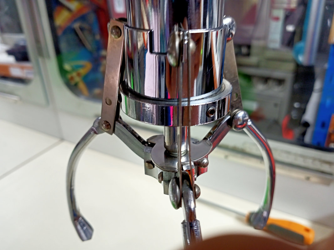
View of the claw and gantry assembly from below.
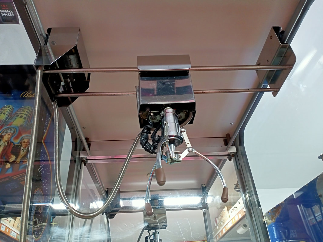
A very helpful resource for the disassembly and servicing of this part of the machine is actually the operations manual for another machine; the pink LAI skill tester released by LAI in 1999. The claw mechanism and gantry assemblies are very similar to this older model of skill tester, and the manual contains good quality diagrams.
Servicing the gantry and claw assembly is easy. Unplug the gantry wiring harness from the rear bottom section of the cabinet (1 connector). Then, push it up through the playfield floor. There is a glass channel that the wiring harness is threaded through. My connector didn't fit through this channel, so I removed it and brought it with the assembly. Then, simply lift the gantry off its rails, twist it, and pull it down and out of the machine. You may need to remove a rail locking bracket which secures the rollers on the right of the assembly to the rail before you can lift it off. Mine was already loose, so I could just lift the rollers straight off. The part of the gantry attached to the claw can be lifted slightly and pushed to the centre of the machine. This gives you some more space to handle the mechanism.

Lifting the claw gantry out of the cabinet. Claw had been moved to centre for better balance.
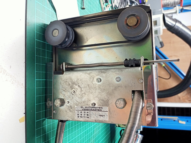
With the assembly on the bench, there's a couple of things you can check right off the bat. The drive belts on the left and right sides on the mechanism should be intact and smooth. The rollers should also turn with ease. On the left side on the mechanism is a long, spring-loaded pole. This activates a switch when pressed in (switch 1). Check this switch is activating properly, as this switch tells the machine when the gantry is at the home (front) position.

Claw gantry assembly, left side. Spring-loaded pole is for the home position switch.

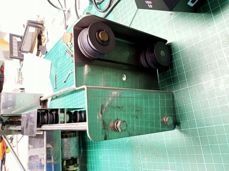
Claw gantry assembly, right side. Note the rail locking bracket has already been removed.
At this point, it is generally easier to remove the claw mechanism from its rails so each part of the assembly can be looked at individually. The two lower rails on which the claw mechanism sits can be removed by undoing two bolts on either side of the assembly. The upper rail is more of a pain to remove as the roller driver shafts are connected to it, so I left it intact. Once the lower rails are removed, the claw mechanism can be freed. Put it aside, and we'll deal with it later.
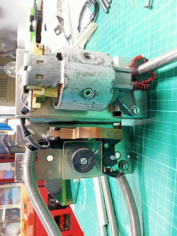
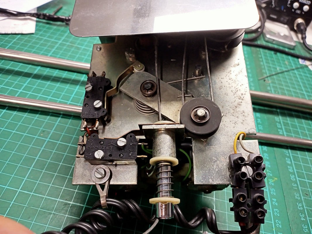
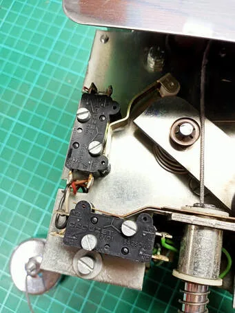
Let's look at the forward/reverse section of the gantry assembly (left side) first. There are two screws holding a cover over the motor and switches (visible in the photo above). Remove these and the cover can be slid off. This reveals the motor that drives the gantry forward and back. There are two switches mounted underneath it. The one towards the rear of the assembly is activated by the long pole I referenced earlier (switch 1). The one towards the front of the assembly with the thick, bent actuator (switch 2) is activated by movement of the claw mechanism, and tells the game when the claw assembly is in its home position (left). Check for proper operation of these switches. I found that switch 2 was activating too late, causing the claw mechanism to crash into the gantry. Adjusting the actuator outwards a bit helped to stop the claw a little earlier. There is a rubber bumper here to absorb any impacts.
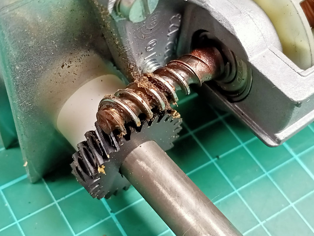
The motors are the most important part of the whole machine, so make sure the rotors move freely. The point where the motor shaft interfaces with the drive gear needs to be greased. The grease on this one had dried up and turned solid, so I cleaned it out and applied new Teflon grease (Supercheap). I did this to all of the motors throughout the rest of the game, too, as they were in much the same condition.

Forward/reverse gantry section, including forward/reverse motor (top) and switch 1 and 2 (bottom).

Dry grease on the drive gear and motor shaft.

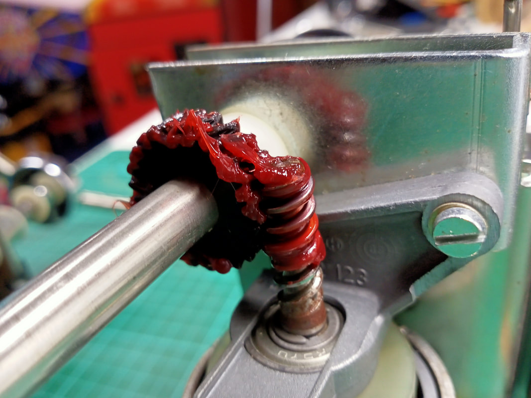
New grease applied.
Next, the claw mechanism. There are steel plates on the top, front, and rear sides of it. The rear plate is secured with a nut. Remove it and pull the cover off. The front plate is secured with friction, and can be slid down. The top plate is riveted to the frame of the gantry, and isn't easy to remove. I left it in place.

Claw mechanism assembly, front side with cover removed. Limit switches and control arm are visible.

Claw mechanism assembly, rear side with cover removed.
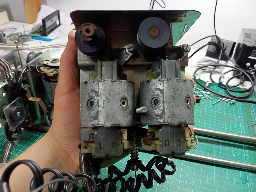
Let's look at the rear (motor) side first. Based on the orientation I have them in the photo above, the motor on the left drives the claw up and down. The motor on the right drives the claw mechanism left and right on the gantry. Both of the motor shafts and drive gears had dry grease on them, so this was cleaned up and new grease applied. There's not much else going on on this side, so let's move to the front side.
This side features three pulleys, with string wrapped around them. The pulley at the top right is the claw string spool, and when the motor behind it turns on, it spins and releases string so the claw can descend. The mechanism here is quite interesting. The switch at the bottom of the assembly (switch 3) closes, indicating that the claw is no longer in its home position and is descending. When the claw reaches the playfield, or any other obstacle on its way down, tension is released from the string. This causes the spring-loaded armature (claw control arm) to pivot, activating the switch on the left side of the assembly (switch 4). This tells the game that the claw has reached the playfield.
Close-up of the claw mechanism including switch 3 (bottom) and switch 4 (top).

At this point, the claw solenoid will engage, closing the claw, and the motor will reverse direction, raising the claw. Once it reaches the top, the switch towards the bottom of the assembly (switch 3) will open, telling the game that the claw has docked and the gantry can return home (hopefully with a prize!). Ensure you check the switches for correct operation here, as they are essential to the claw working properly. The switch actuator for switch 4 can get pretty mangled, so make sure it closes properly when the control arm moves.
Next, the claw itself. I found it easier to unwind some of the string from the spool so that I could pull the claw away from the main assembly to pull it apart. Two screws at the top of claw hold its cap on. Removing this provides access to the claw solenoid. Two wires are attached to it. They were only weakly attached to my coil and broke off when I moved them a little, so it's a good idea to check these wires if your claw is only grabbing things weakly (if at all).
The rest of the claw needs to be disassembled from the base. A single screw holds the pivot hub (where the claw arms meet) to the body of the claw. Undo this, and the plunger and adjustment washer can be removed from the claw. The adjustment washer position can be adjusted to change the "reach", or maximum opening size, of the claw. This needs to be adjusted, by rotating, based on the size of the prizes on the playfield.
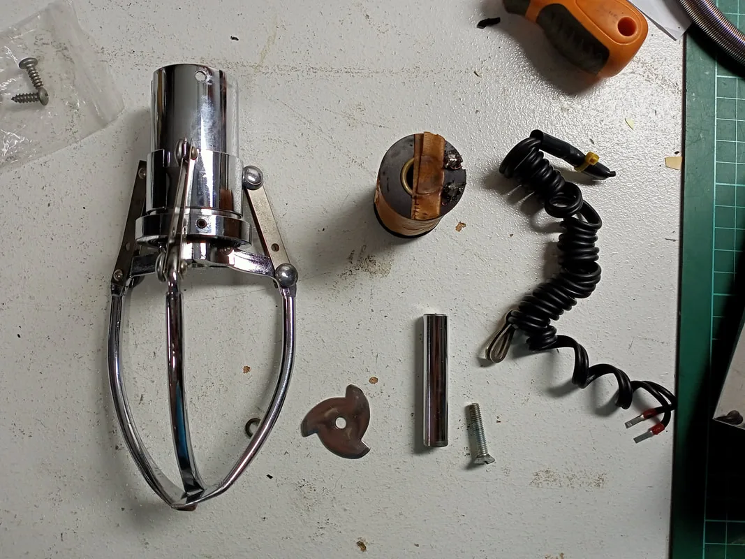
Claw after partial disassembly.

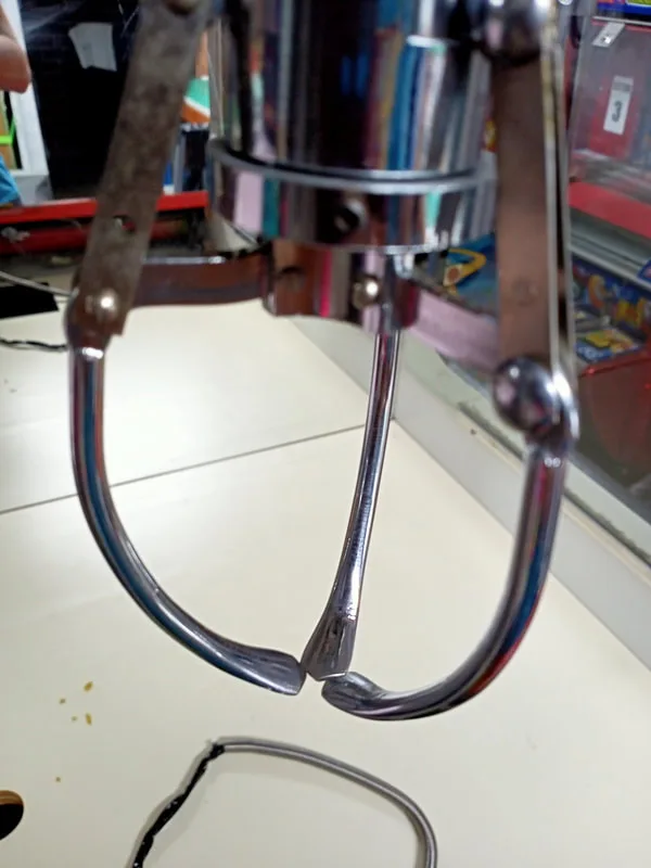
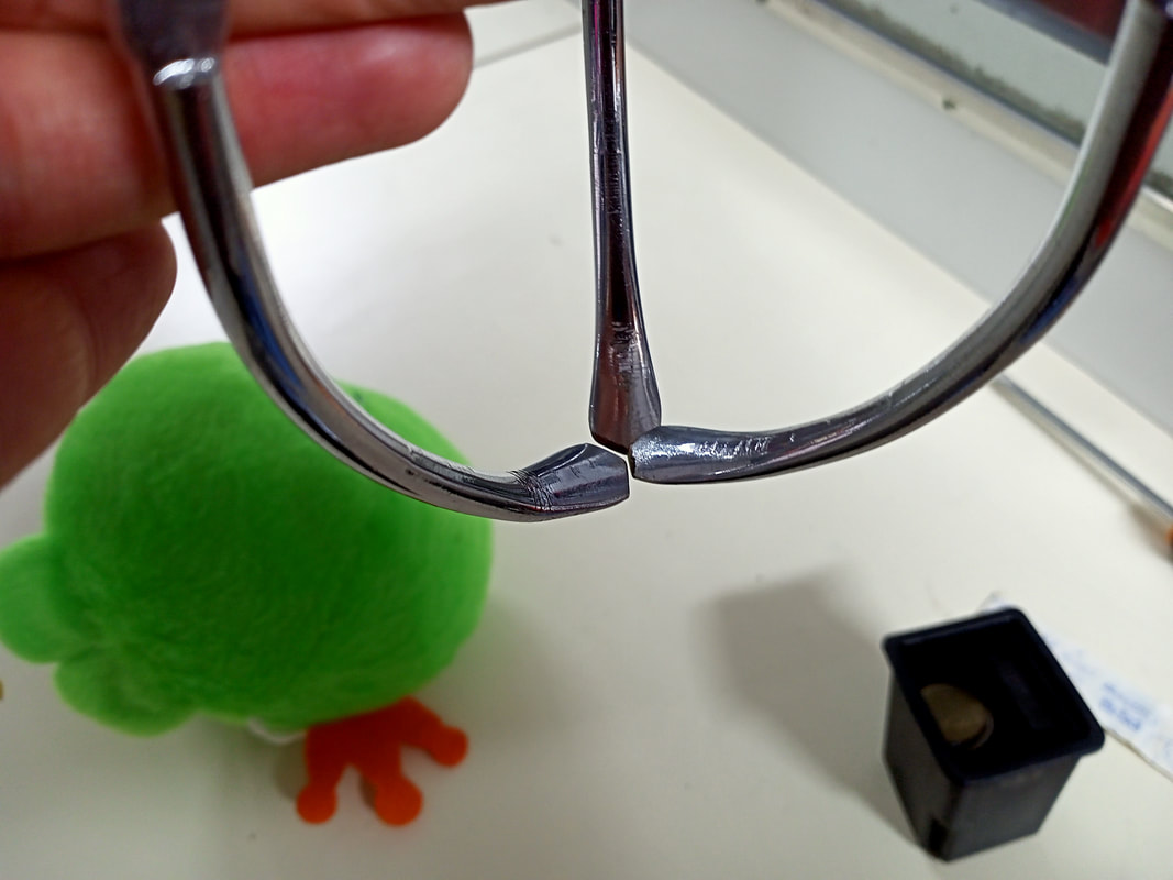
The main issue I was having with this claw was that it sometimes got stuck in the closed position. It didn't appear to be an electronic problem as it was intermittent, so I started looking at mechanical issues. I noticed that the claw arms sometimes overlapped when the claw closed. When I noticed this I tried to pull them apart, and realised that it required a bit of force and jostling to get the arms to disentangle. This is what was causing the claw to bind: the arms were closing, overlapping one another, and getting stuck. The claw arms should not not be overlapping like this, and should meet each other in the middle with (limited) contact.
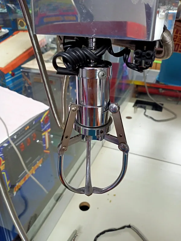
Claw stuck with arms overlapping each other.
Claw stuck with arms only slightly overlapping. Still an issue!
The position of the claw arms when "closed" can be adjusted by moving the collar on which the pivot ring (the part where the claw arms attach) sits. There are two set screws holding it to the claw body. Loosen them and move it down to open the claw arms, or move it up to close them. Adjust them so the arms are almost touching when the claw is fully closed.

View showing the set screw to adjust the collar on the claw body.
Claw adjusted to the proper closing position.
A clean and service of all of the claw and gantry components seemed to help make the whole system run more smoothly. Don't forget to add rubber tips to the claw arms, too. This helps when grabbing hard surfaces (i.e. plastic toys) over the bare metal arms. I used pinball shooter rod rubber tips for this (RTBB, PSPA). They fit perfectly!
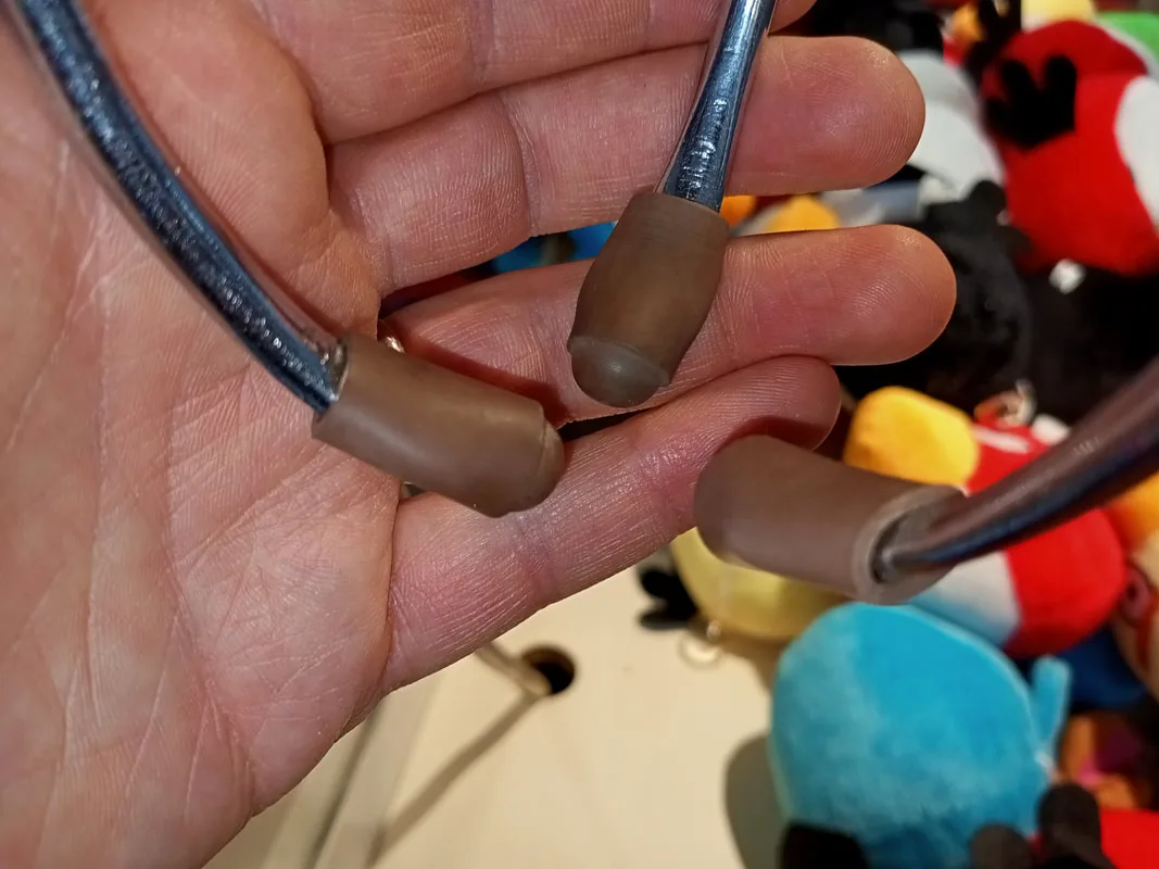
Don't forget the rubber tips!

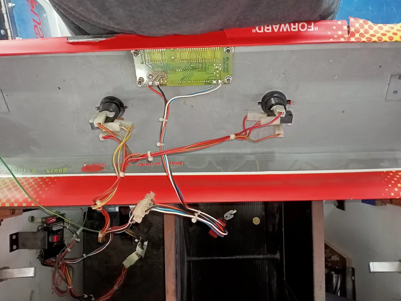
Control panel, rear side, showing the button housings, switch and lamp assemblies, and credit display board.

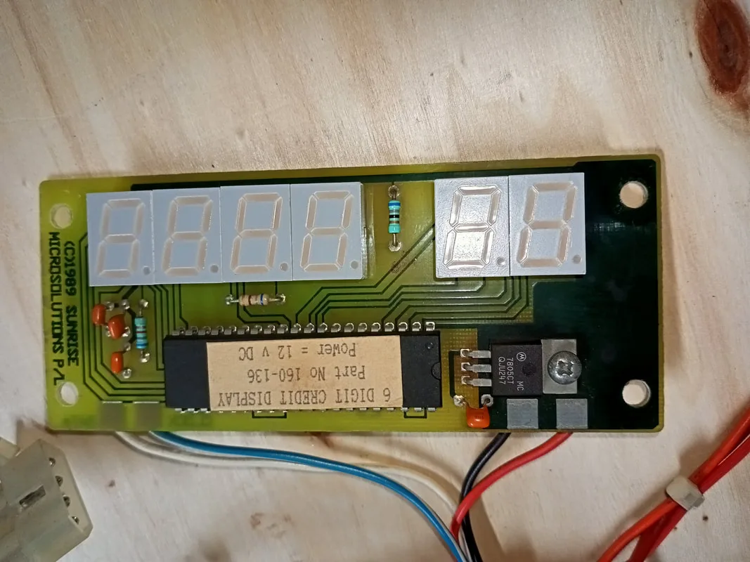
Front side of the credit display board.

I made one small modification to the buttons. They are supposed to be yellow (left) and green (right). But they have no text or graphics on the buttons themselves. I decided to change that by printing "FORWARD" and "RIGHT" on each of the buttons to make it clearer to people what each button does. I know it's written right there on the control panel, but nobody reads that, do they? I measured the size of the interior of the button window, and printed some test graphics. They fit well, and the text looked good, but printing on regular white copy paper resulted in very little light from the lamp getting through. So I reprinted them on a transparency sheet. They look good! Note: use a laser printer for this, as my inkjet printer's ink did not stick to the plastic sheet.
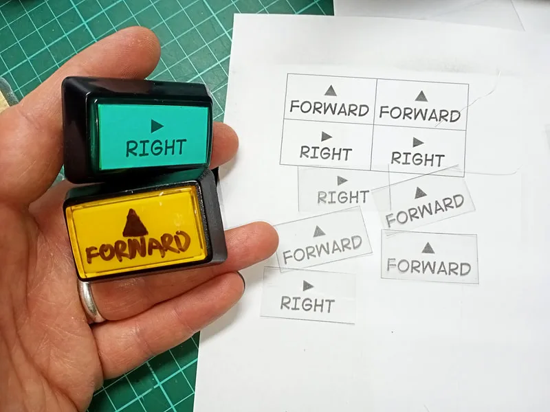
Button window graphic test prints.


New button graphics installed.

Coin mechanism and credit board setup.
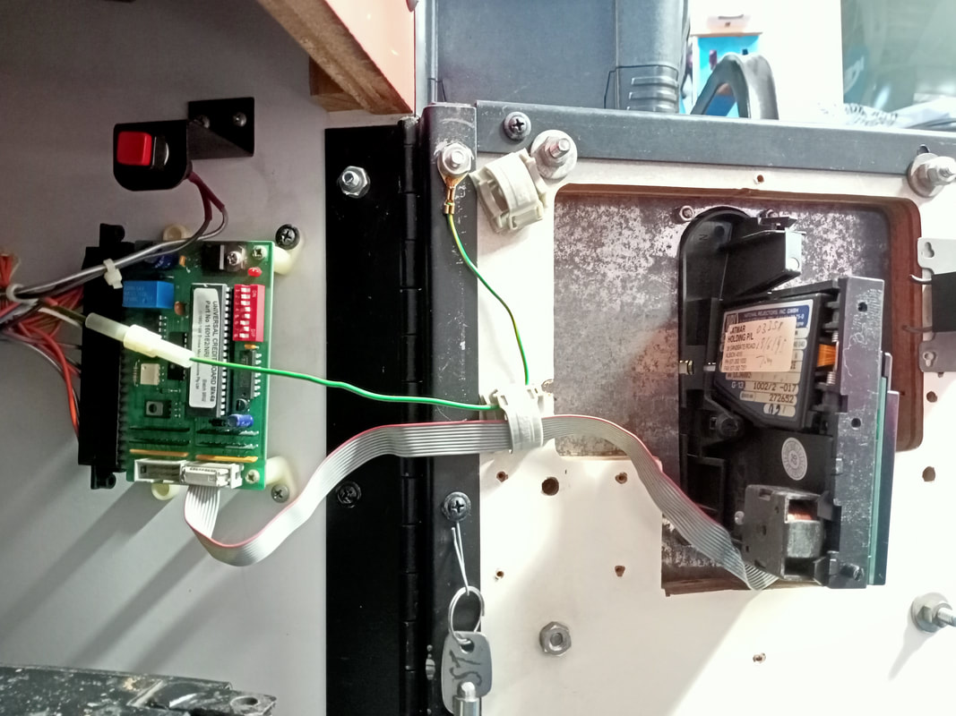
As far as I can tell, the control boards were originally designed to interface directly with mechanical coin mechanisms. I've never seen an LAI skill tester with mechanical coin mechanisms, so I assume these cabinets all had universal credit boards installed. Some of the relays and components towards the bottom side of the board function as the credit handling system. So if your game is not accepting coins, suspect one of these components, such as relay R4.
Reassembly
The mechanisms in this game are fairly simple, so reassembly is just a matter of following the photos you took and doing disassembly in reverse. There was a lot of muck and dirt on this game, but it looked nice after a deep clean.
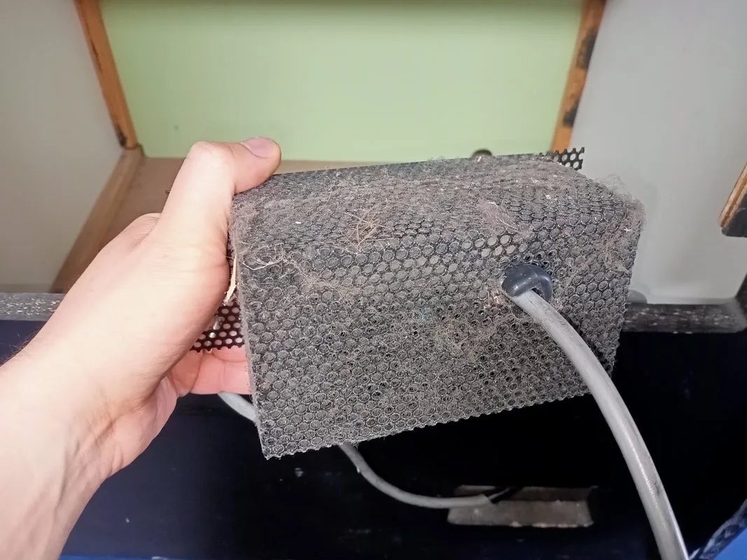
Dust guard at the rear of the machine.

Cabinet base before cleaning.
All clean and with a new cable installed.
Cabinet base after cleaning. Transformer panel not yet installed.
Cabinet head before cleaning.


Cabinet head after cleaning. Neon transformer not yet installed.
Top of the cabinet mid-clean. The front 2/3 is clean but the fan is still gross!
Top of the cabinet after cleaning.

Conclusion
I typically consider skill testers and similar redemption games to be a bit icky. I don't like the element of chance that most skill testers employ in order to keep them profitable. However, getting to know this machine has made me realise that they are not all set out to get you in devious ways. This machine only has a single adjustment for claw strength, and when set appropriately for the prizes on the playfield, it can quite consistently be "won". Of course, you can't just grab any prize without first considering its size, weight, and position. But once you get a feel for the way the claw grabs onto items, and what it can reasonably move, then winning becomes quite easy. But this is only if you know how the system works, and only if the operator hasn't set the claw strength to an unreasonably low level.
I originally planned to fix this game and sell it on, but I am now thinking about potentially routing it somewhere. It would be awesome to see this machine's neon shining out in public again, so it may appear in an arcade near you sometime soon! Especially with the invasion of cheap and nasty crane machines with dazzling LEDs and blasting music, I think this style of cabinet is a welcome throwback to simpler times.