- Published on
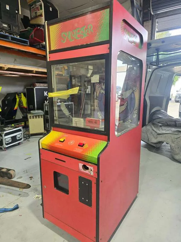
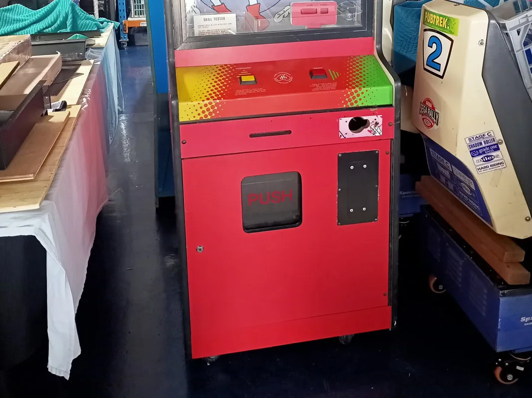
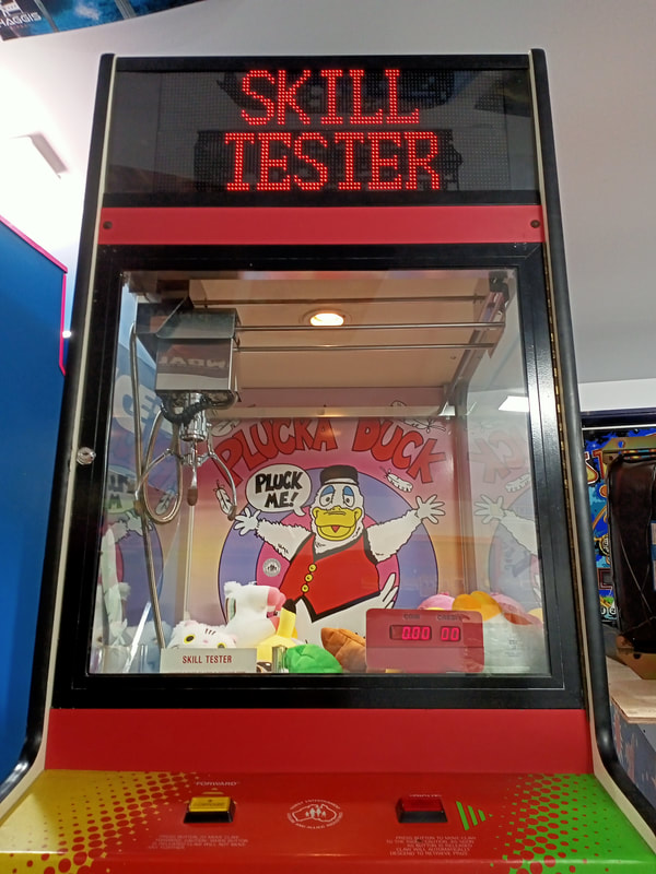
Leisure & Allied Industries "Skill Tester" (Type 2)
- Author
-
-

- Name
- Posts
- Posts
-


No, you're not seeing double. My last machine restoration post was also about an LAI Skill Tester. It's not often I get a double-up of machines, but while I was in the throes of finishing up repairs to the first LAI Skill Tester, I saw an ad on Facebook from someone who was giving another one away. Sweet! These machines aren't worth much, and there don't seem to be many people who have the desire or ability to fix them. But I'm a sucker for retro technology, so it's right up my alley!
What's this got to do with a Skill Tester? Apparently, a number of LAI Skill Testers were used on the show during one of the Plucka Duck segments. These units had decals installed on the cabinet and glass panels, had a Plucka Duck poster attached to the rear wall of the play area, and were filled with Plucka Duck plush toys. I've been searching forever to try and find evidence of this segment on YouTube but have turned up empty so far. If you find one, please contact me!
Initial condition report


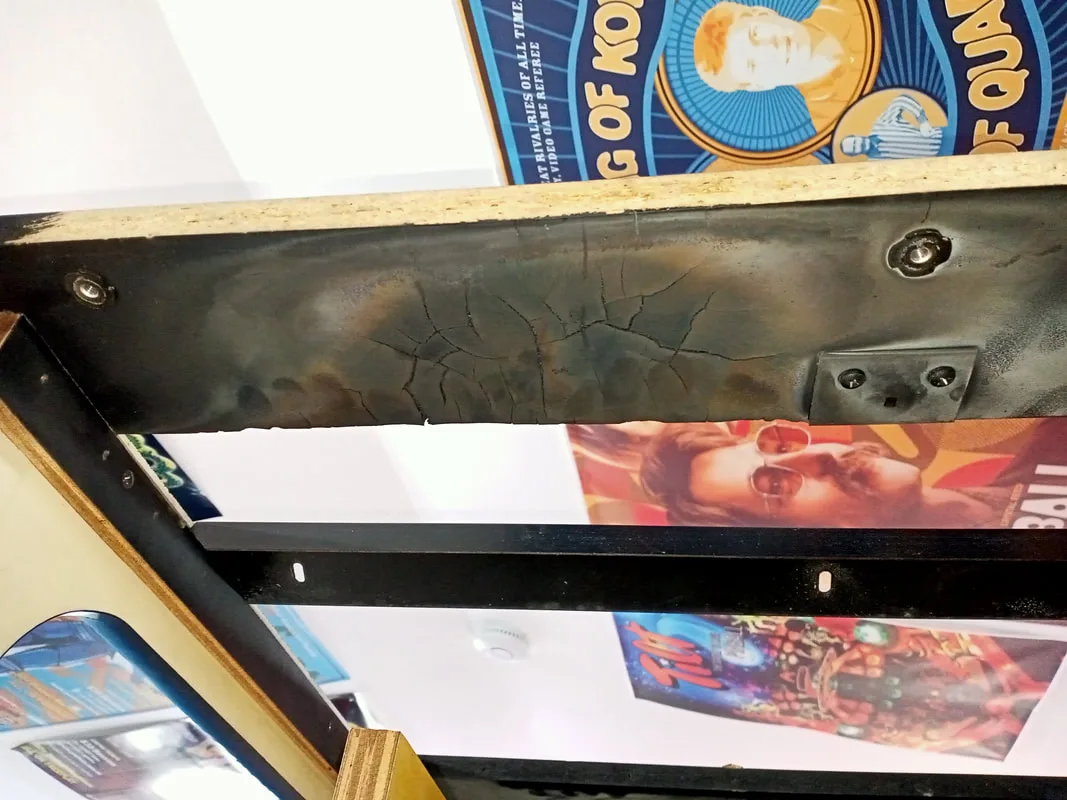
- Timber cabinet in good condition, apart from the interior of the head, where there had been a small fire (lol).
- Missing original neon marquee.
- Castor wheels intact and rolling nicely.
- Playfield (prize bed) quite dusty and grimy but no significant damage.
- Claw mechanism not returning to home position. Claw not closing consistently. When closed, it is extremely weak.
- Machine would not boot up. Missing power supply.
- Power cord missing.
- One fluorescent lamp in head not working, one missing.
- Missing coin mechanism and credit board.
The thing that was interesting to me when inspecting the machine in detail was, of course, the fire damage in the interior of the head. These skill testers originally had a neon marquee here. Unfortunately the neon was nowhere to be found on this machine, and had been replaced with one of the side marquees on a sheet of polycarbonate. When I opened the head, I noticed some fire damage to timber cross beam immediately above where the neon lamp was originally mounted. The neon lamp is a high voltage fixture, and based on my examination of the lamp in my other LAI skill tester, it is completely unfused. It appears that some kind of fault occurred with the neon on this machine, causing it to catch fire on its left side. The fire burned upwards to affect the timber above, resulting in the damage. The timber was still mostly intact, and was still strong enough for its purpose of bracing the topper and cabinet head. So I cleaned it up as best I could and left it be; an awesome piece of the machine's history!
Nothing like a bit of fire damage in your arcade cabinet to set the tone for the restoration!
This was the first "Type 2" skill tester I've had to work on. I documented the differences between Type 1 an Type 2 skill testers in my previous blog post. The experience I had gained with the Type 1 machine was useful, but not completely relevant to this machine as the control circuitry and wiring is quite different. I'll explain how each of these components work in the sections below.
Disassembly
One of the improvements of Type 2 machines over Type 1s is much better access to machine internals. The power distribution box, transformer panel, and main bridge rectifier and filter capacitor are secured behind a cage in the bottom of the machine. This is accessed via the pull-out door panel at the rear of the cabinet. Unscrew the cage (two screws on top, two at the front side) and all of these bits are revealed. Hopefully you shouldn't have to do too much here. The transformers supply the higher voltages (around 60 VDC) required for the gantry motors and claw assembly, as well as lower voltages (12 VDC) for other functions.
On this machine, I observed a number of connectors drawing power from the distribution box, including two connectors for the two transformers I just described, one for the 240-volt prize dispensing sensor in the prize chute, one for a 12-volt portable transformer which had been mounted to the base of the cabinet (no longer used), and one which ran up towards the marquee area of the cabinet to supply all of the electrical devices up top.
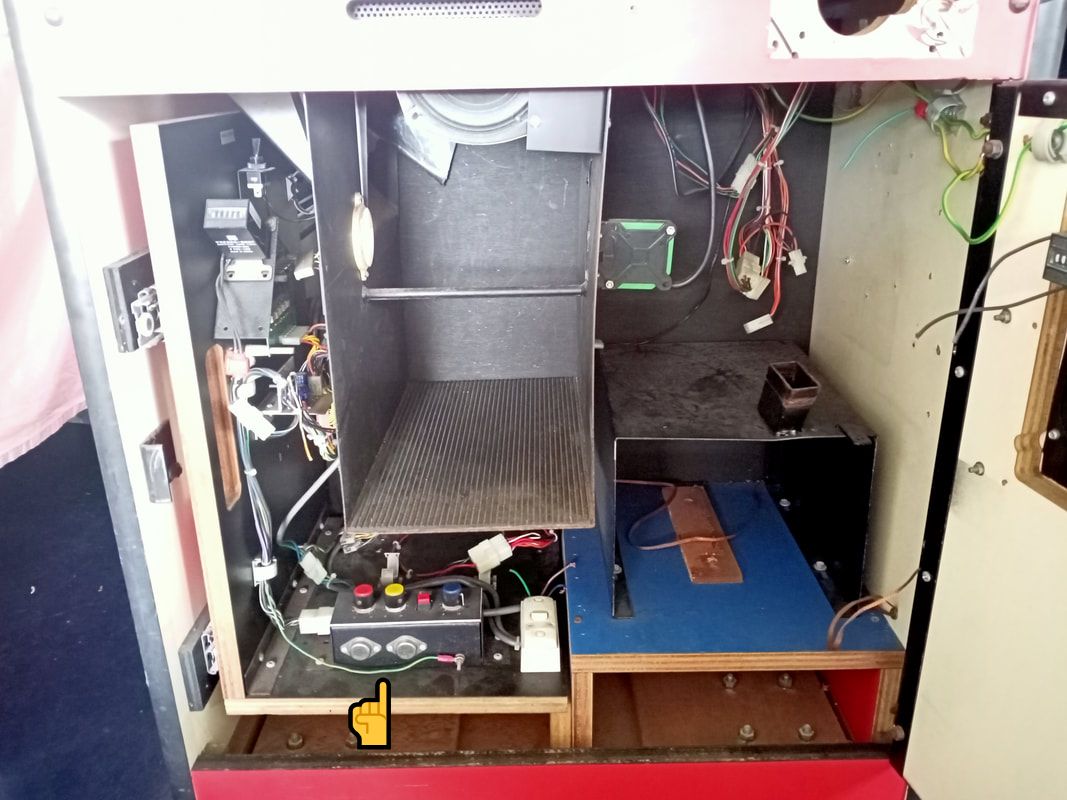
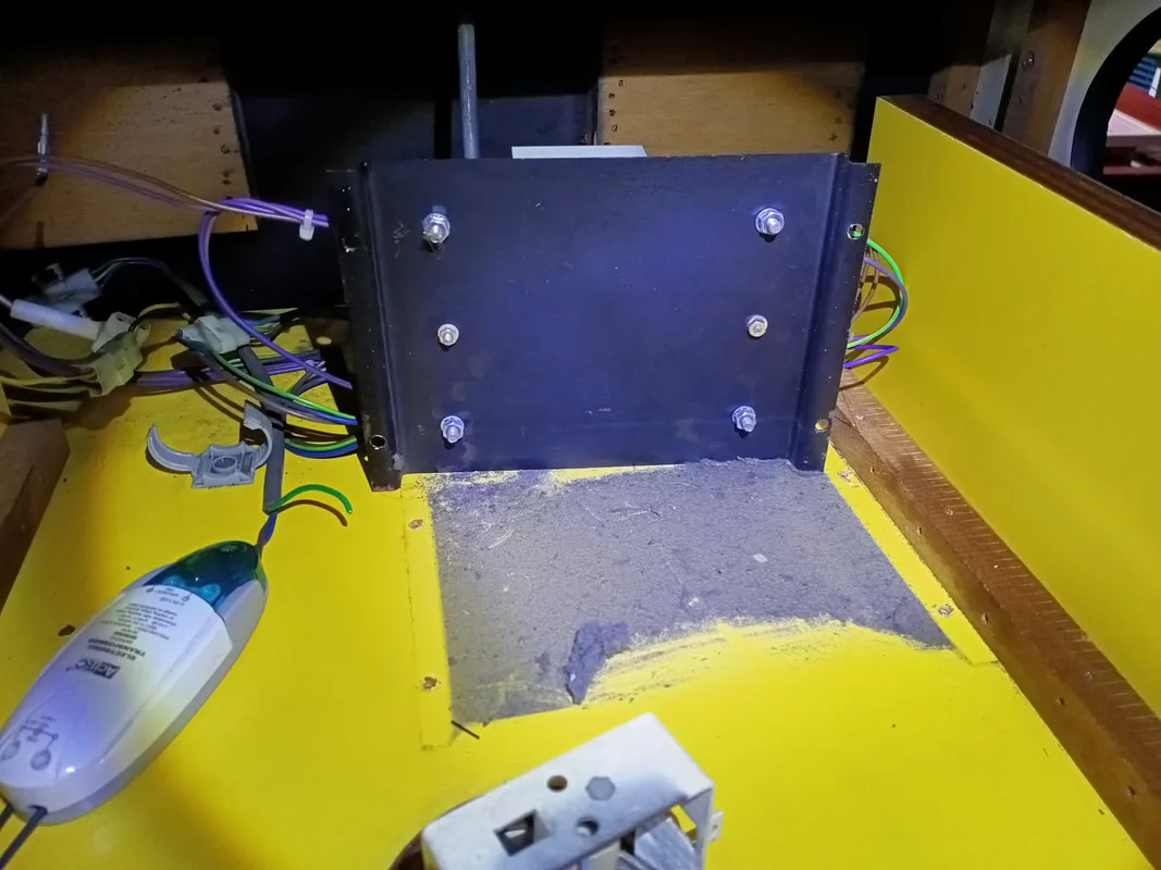
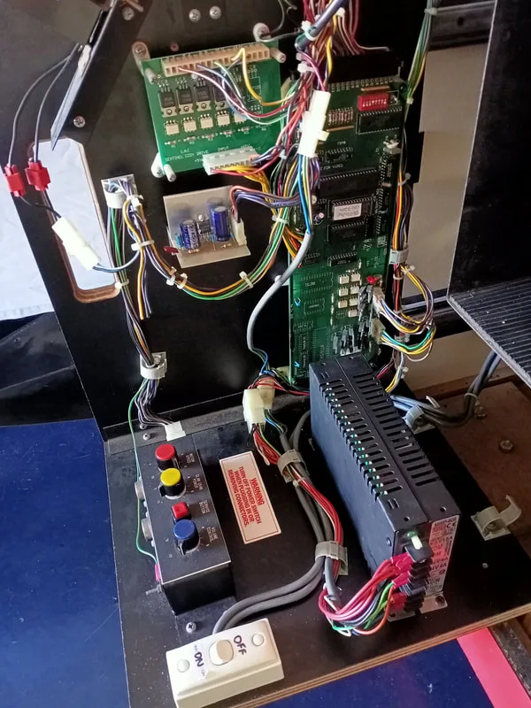
The main logic control board is accessed from the front of the cabinet. Open the bottom door, and pull out the timber tray (bottom left) containing the logic board, control box containing potentiometers for volume, claw and motor control, switching power supply, coin and prize counters, and credit boards.

Front of cabinet with door open. Arrow indicates the pull-out tray with circuit boards and controls.
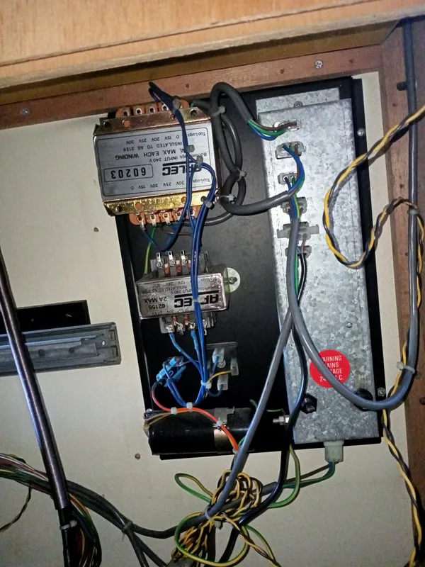
Transformer panel and distribution box at the rear of the cabinet.

Of course, opening the top door to the playfield area provides access to the prize bed. The marquee can be removed by undoing the metal trim piece on its top edge. The marquee and top cabinet area can be accessed by lifting out the door panel on the roof of the cabinet.
The main mechanism of the machine requiring any serious disassembly is the claw mechanism and gantry. I'll cover those in detail in the relevant section below. I did a bunch of stuff on this machine compared to the last one, so let's get into it.
Tips & Troubleshooting
Plug cut from power cable.

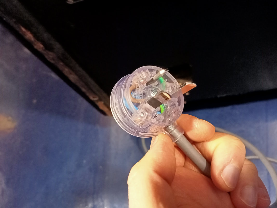
New power plug installed.

Contents of the marquee area in the head of the cabinet.
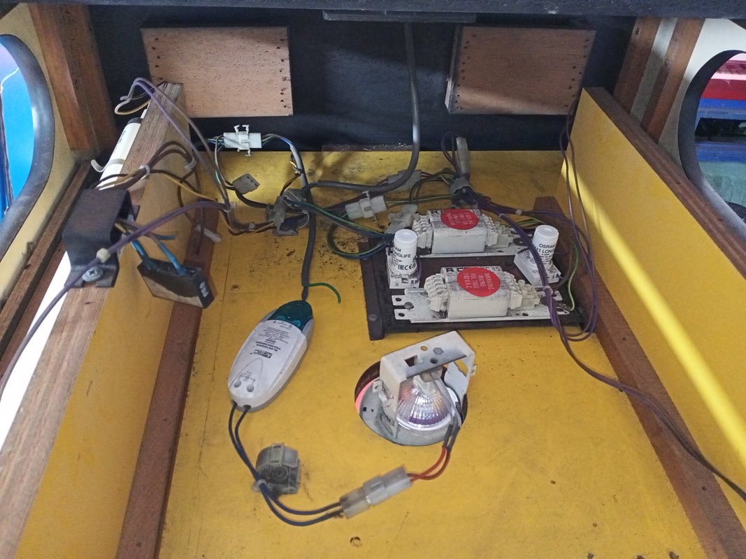
There is a fluorescent lamp on either side of the cabinet, to light up the side marquee graphics. There are some ballasts for the fluorescent lamps, a downlight, and an electronic transformer for the downlight in the centre of the marquee area. A fan sits on the ceiling towards the rear of the space to ventilate everything.
Light fitting on the left side of the cabinet: no light!

Right side: also no light!

Neither of the fluorescent lamps were lighting up. I took out the lamps, plugged them into a working fitting in my other skill tester cabinet, and neither of them came on. So, as the tubes appeared to be shot, I bought a couple more (Bunnings). When I installed them into the game, neither of them turned on. Still at square one!
Time to have a closer look at the other bits and pieces in the lighting circuit. Each fluorescent lamp has a ballast and a starter. I realised that the reason that the lamps were not lighting was because one of the starters was completely missing, and the other had blown its top and was no longer serviceable. I installed a couple of new starters (Bunnings). Thankfully both of the ballasts were still in working condition, and the lights flickered on and worked as they should. I also took the opportunity to clean the topper area, including under the ballast mounting plate. It was filthy!
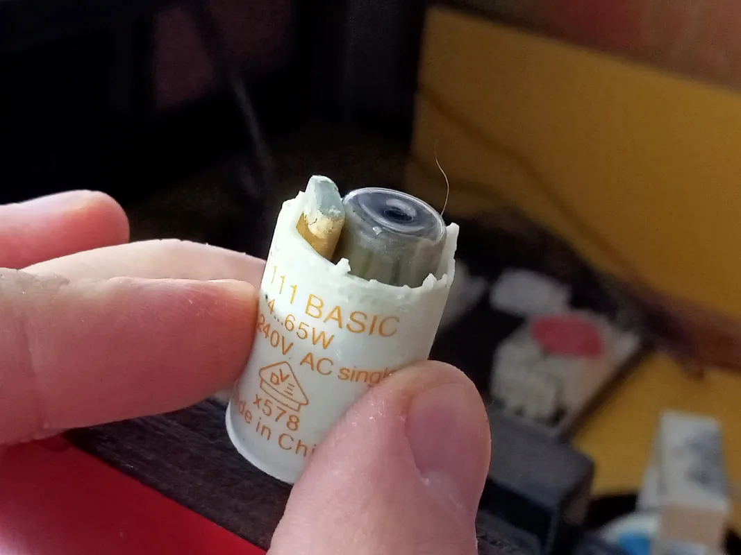
The lamps will never light with a blown up starter!

Dust and debris under the ballast mounting plate. Filthy!

At this point we had lights shining down on the prize bed, and lights shining out either side of the marquee area. There were no lights mounted at the front of the marquee area on this game, so that's all the lighting I needed to worry about for now. One of the side marquee plastics was also missing; I assume this was removed so it could be used at the front of the machine (see section on the installation of a new marquee). Thankfully, I had one spare print from when I reproduced these marquee plastics for my first Skill Tester restoration, so I could put that one straight in!
Left side marquee lighting up...

...and so is the right!

Next step was to inspect the main logic (CPU) board. Everything seemed to be plugged in. There is a 36-pin edge connector on the top of the board, and four smaller 0.156" Molex-style plugs on the bottom right. On the left side, approximately halfway up the board, is a smaller 0.100" connector. No issues evident with any of those connectors. Time to take the CPU board out and take a closer look...

Main game logic (CPU) board.
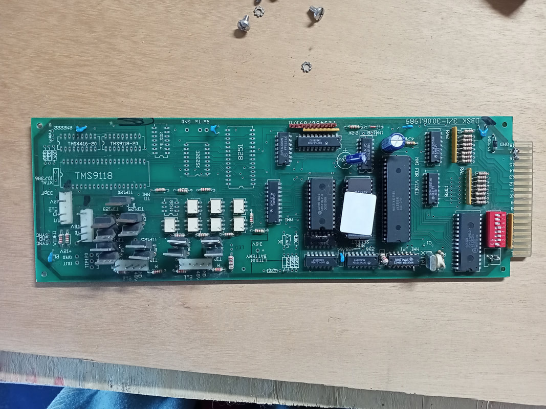
The component side of the board all seemed OK. No blown up capacitors, no corrosion and no other signs of damage. I noted that some of the board appeared to be unpopulated, namely the bottom left section. This section appeared to be unpopulated from the factory as opposed to each of the components being removed at some later point. The missing components included a TMS9118 video display controller chip, RAM module, communications chips, and a crystal. Some unpopulated connector slots are labelled "SYNC" and "Rx", "Tx". Obviously this board had some kind of basic video processing capability, and the ability to send and receive data. I have not seen any photos of this board fully populated, so I can only assume these features were scrapped in favour of the simpler credit display on the playfield.
There were a couple of other components further up the board which were unpopulated, too. The largest of these was the lithium battery. I can only assume this board had the ability to save credits after the machine was turned off. One day I might try and repopulate these components to see if that is indeed the case, but I'm getting a little distracted from the main issue at hand. The other component I noticed was missing was a small one with the text "LED" silkscreened next to it.
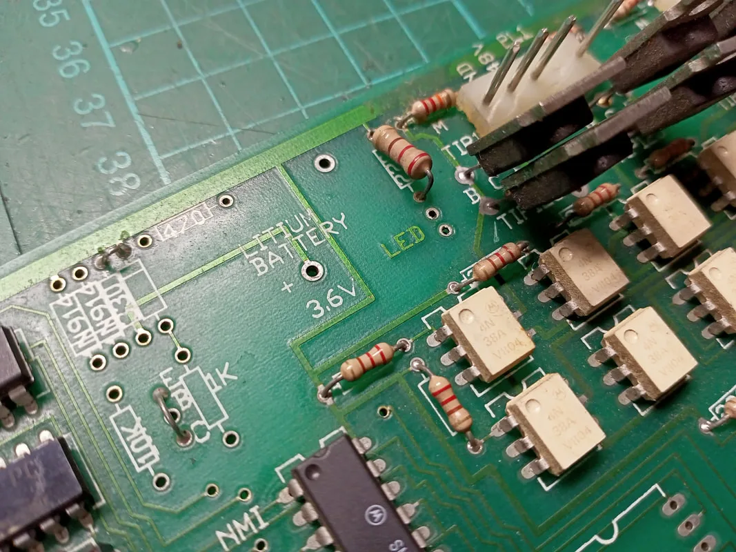
Unpopulated components towards the middle of the board including an LED.

The LED text was a bit of an "aha" moment. Most logic boards have LEDs to indicate that the board is receiving power. Without the LED, I had no idea if this was the case. I measured the supply voltage coming in at a couple of the chips on the board. Simple logic chips are good for this. In the centre of the board was a 74LS373 latch. Supply voltage comes in at pin 20 according to this datasheet. I measured pin 20 and got only a few millivolts. Interesting; there was no power getting to the board. One of the adjacent circuit boards was the Sentinel credit control board. It had labelled pins on the connector pins at the bottom of the board, including 12v, 5v, and ground. I was getting a good 12v supply, but nothing on the 5 volt rail. So I'm definitely missing a voltage. To verify, I soldered in a red LED adjacent to the "LED" silkscreen. Negative (shorter) lead of the LED goes to ground. When powered on, the LED stayed unlit.
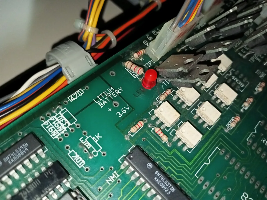
LED installed on the CPU board, but still not lighting up due to a lack of 5 volts.

Looks like I'll need to figure out how to fix the 5 volt supply before this machine can go anywhere. All the power for the cabinet seemed to originate from the transformer panel at the rear of the machine. But none of these transformer taps supplied 5 volts. 12 volts was derived from a 15 volt transformer winding, which was then rectified and smoothed. But nothing for 5 volts.
At this point I did some more research. I found an old thread with some images of the same skill tester on Aussie Arcade, which was very helpful for a number of reasons. It had some photos which proved that, yes, an LED is supposed to be present on the logic board and that it is supposed to light up. But more importantly it showed that there was supposed to be a black metal box sitting on the floor of the pull-out shelf. I had nothing in my game. What was this box? A power supply!
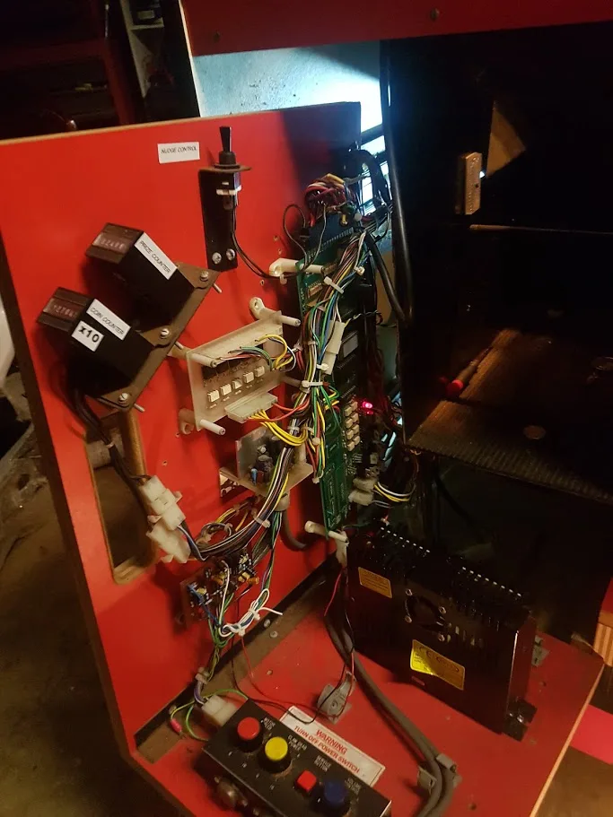
Photo from Aussie Arcade depicting the red LED on the logic board as well as the power supply on the floor of the shelf.

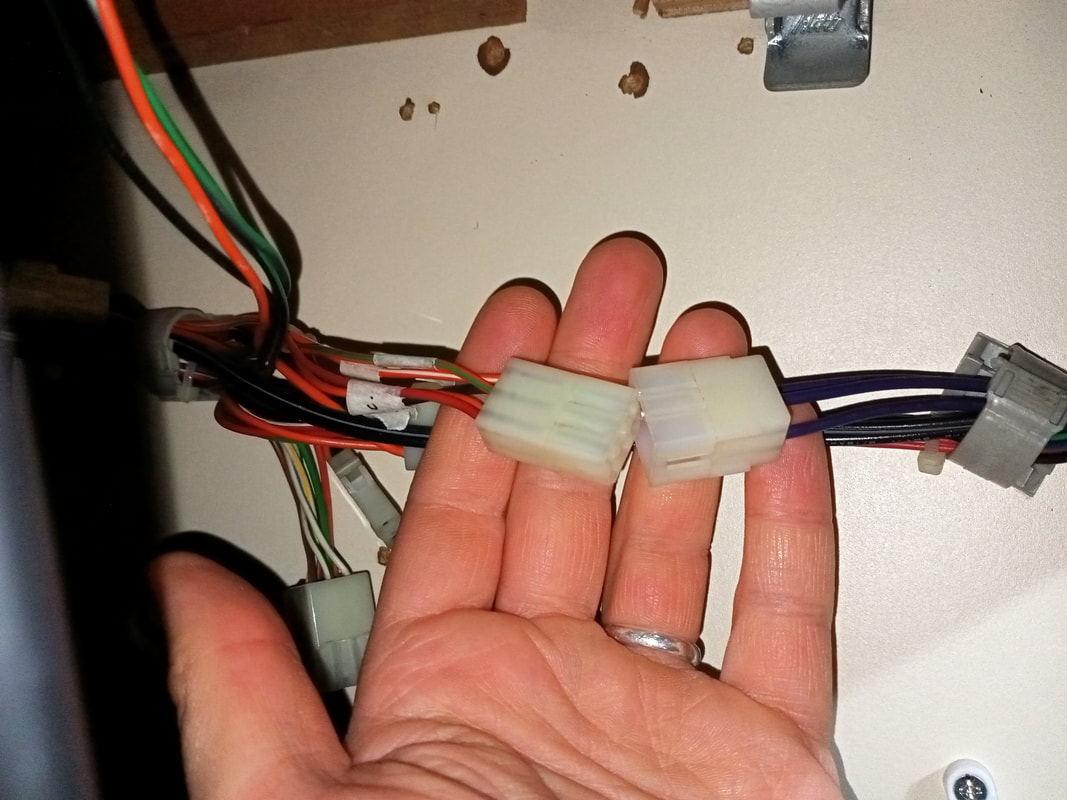
I examined the front of cabinet again. In the cabinet space below the pull-out shelf, I found a small wiring harness which was not connected to anything. This harness had a connector one one side, and eyelets on the other side which were consistent with those found on power supply unit terminals. So, I had found the harness that connects the power supply to the rest of the game. I connected it to a loose connector at the base of the logic board. Then, I checked continuity from the eyelets at the vacant end of the harness to the labelled connector on the Sentinel control board. Using this, I figured out that the wire colours on the harness corresponded to red for 5 volts, orange for 12 volts, black for ground, and white (unknown). I also determined that while 12 volts was already present at some of the game boards, the 12 volt supply from the power supply was for the sound amplifier.
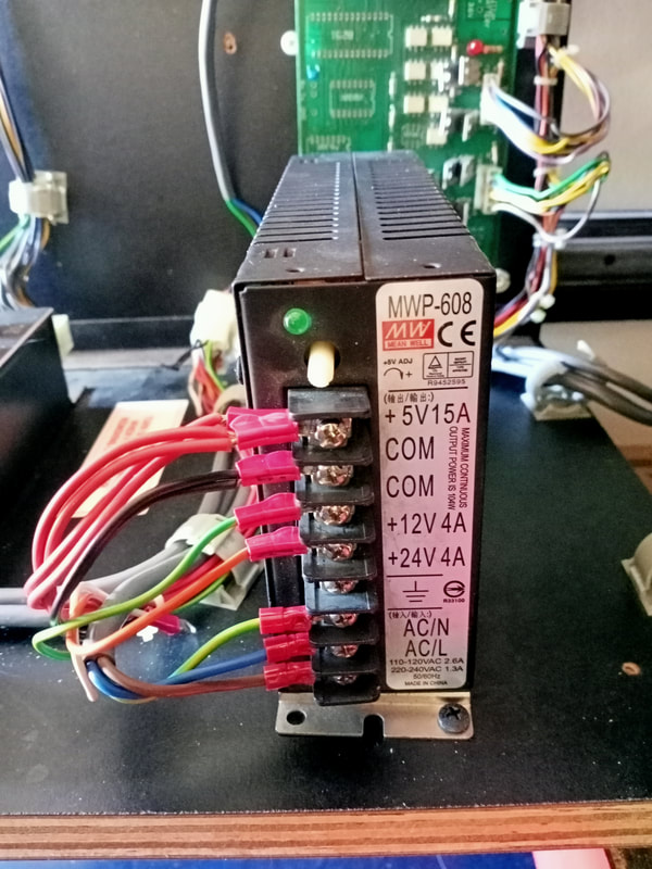
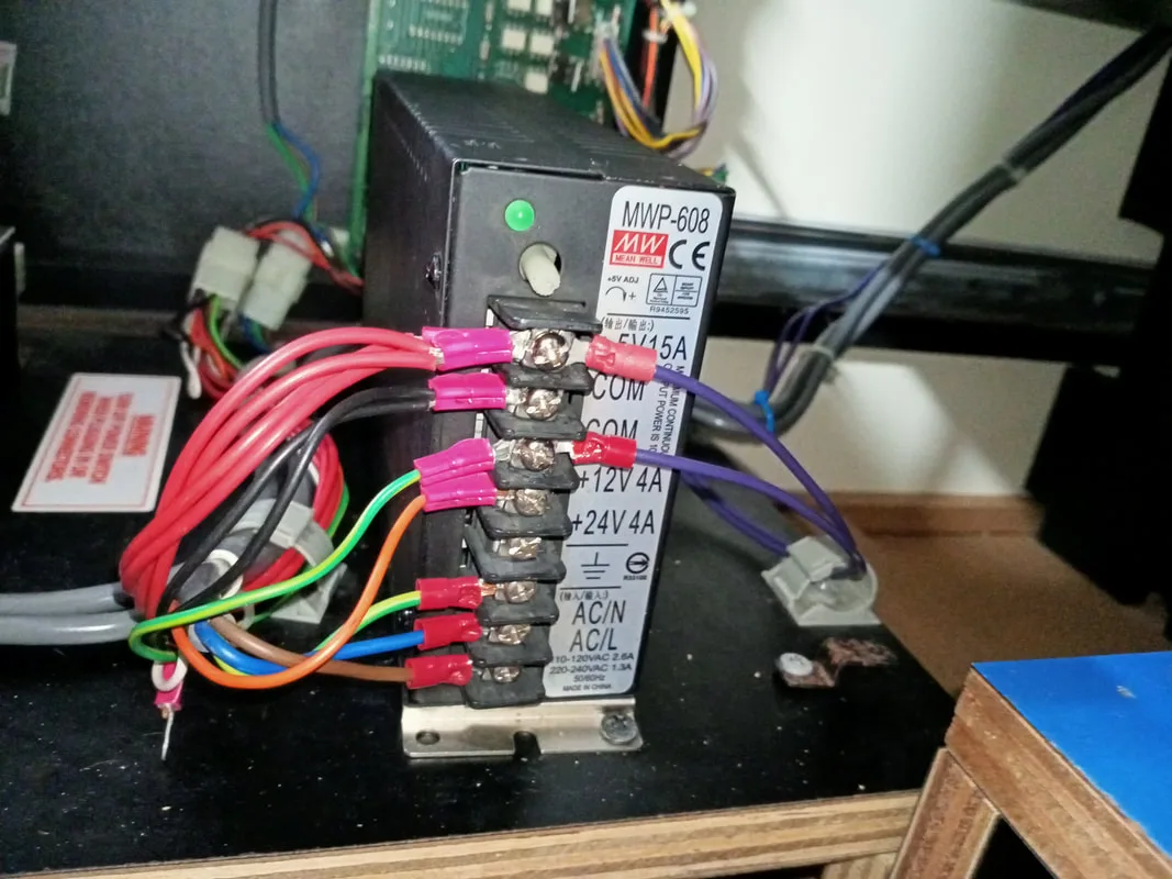
Time to connect a power supply! At first I connected a Happ Controls power supply which are good quality units. However, I still got nothing on boot up. What the heck? After a few checks I still couldn't figure out what was wrong. I changed it out for a Meanwell power supply, the only difference being a greater current rating on the 12 volt rail (4 amps instead of 3). With the Meanwell supply, the game booted right up! So it looks like the machine needs a supply capable of supplying at least 4 amps. Note that the white wire is not necessary to connect to the power supply, as it does not have a matching terminal in the other side of the main harness connector.

Power supply installed and wired in.
The complete board shelf with all components working.
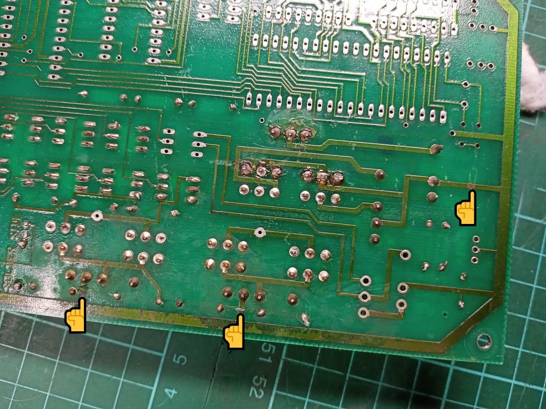
I noticed one other oddity when looking at the CPU board. The rear of the board had several traces cut. These appeared to be the ground traces for each of the connectors on the bottom right corner of the board. These go to the motors and solenoids. I have no idea why these traces were cut, but the game functions normally with them in this state; don't be tempted to repair the traces!

Rear side of the CPU board showing multiple ground traces being cut.

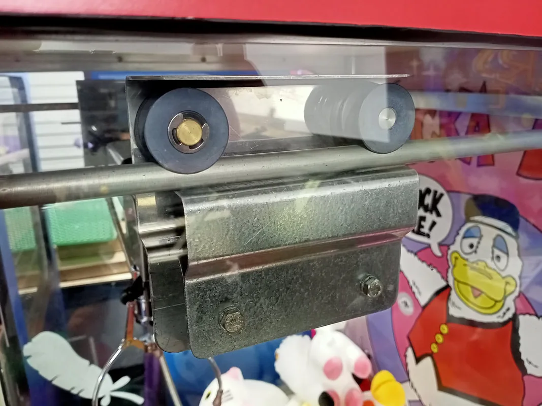
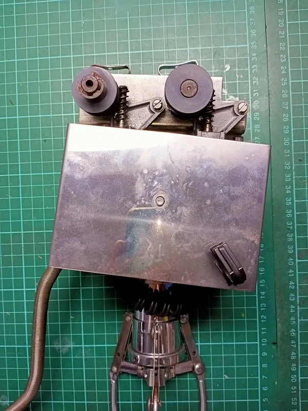
Crane home switch, which required adjusting.
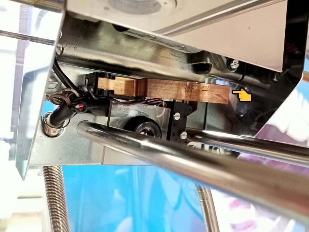
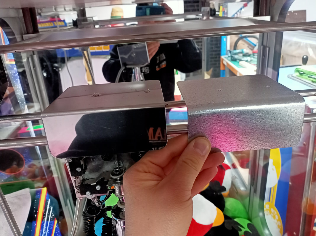
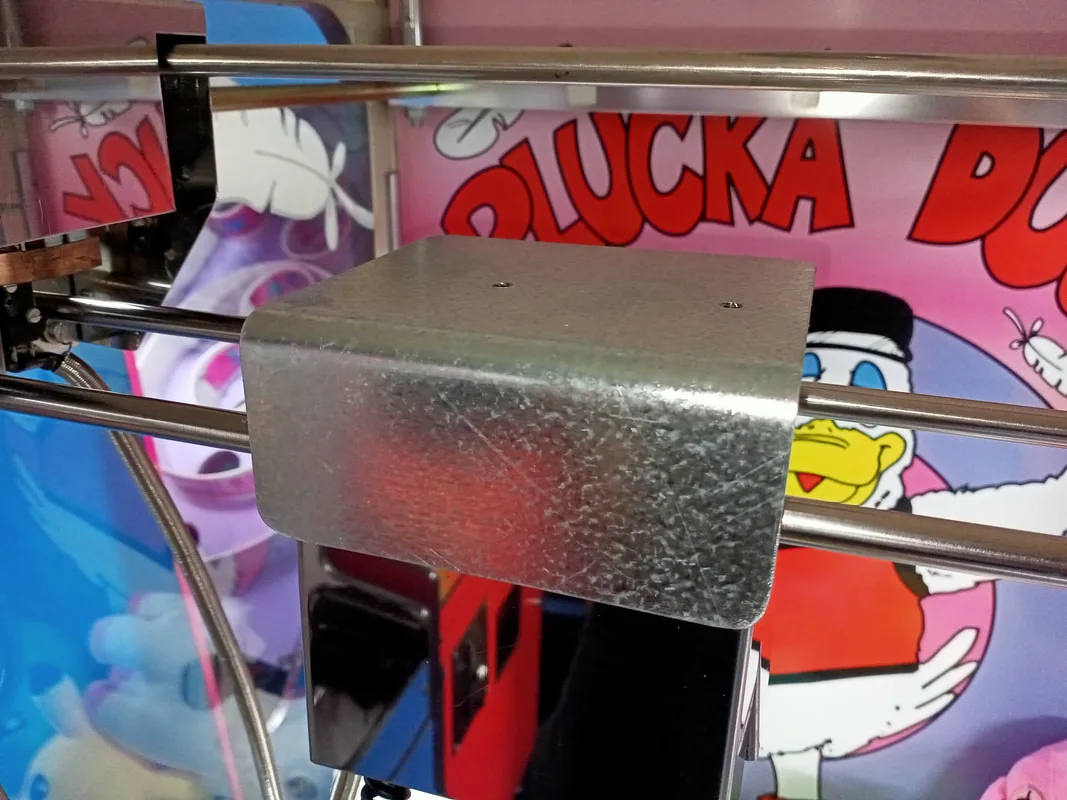
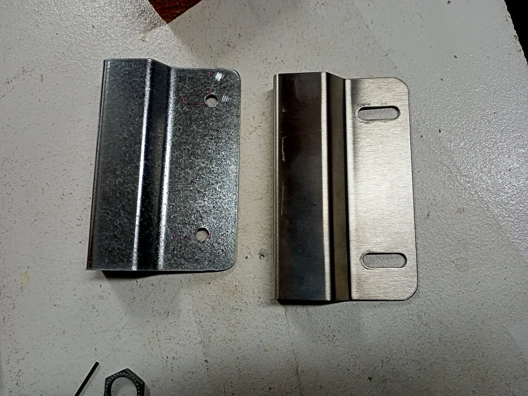
While fixing this switch, I realised that the crane assembly looked a little "off". When I compared it to my working skill tester, I realised that it was missing a part. The metal flap that sits on top of the crane to stop dust and debris falling into the motors and gears was missing. This is a thin flap of metal which bends around the front edge of the crane assembly, covering the mechanism from the player's view. I cut some sheet metal to size, and bent is using a vice to the right shape. I used some galvanised steel sheet (Bunnings) which wasn't as shiny as the original finish, but still looks pretty good.

New top flap after cutting and bending.
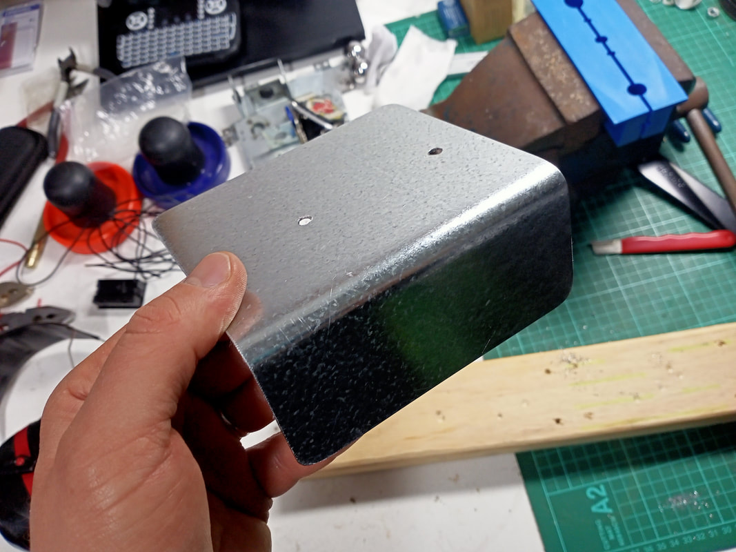

New top flap compared to an original.
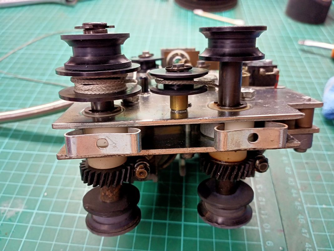
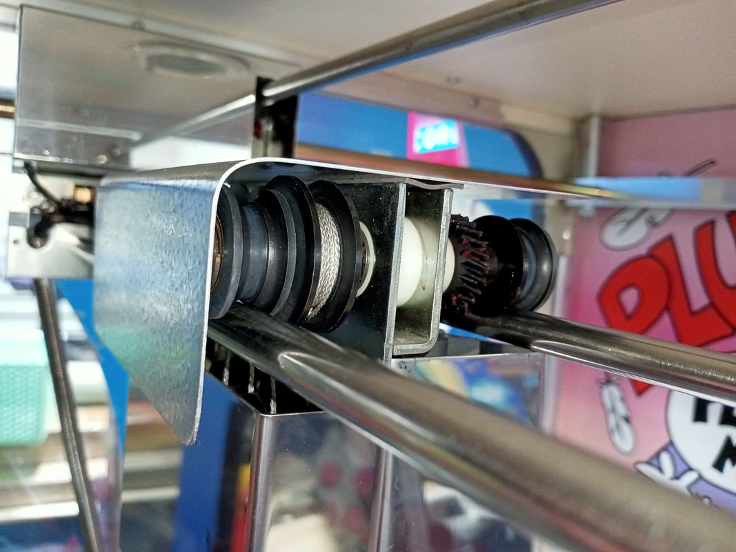
With the shaping done, I had to figure out how to mount the flap to the top of the crane assembly. The flap is supposed to have two clips mounted to its underside, which grab onto the drive shaft bearings and hold it in place. I thought I could use a couple of fluorescent tube hU clips for this purpose as they are about the same size, but they raised the flap too high, resulting in it hitting the gantry when docking to the home position.
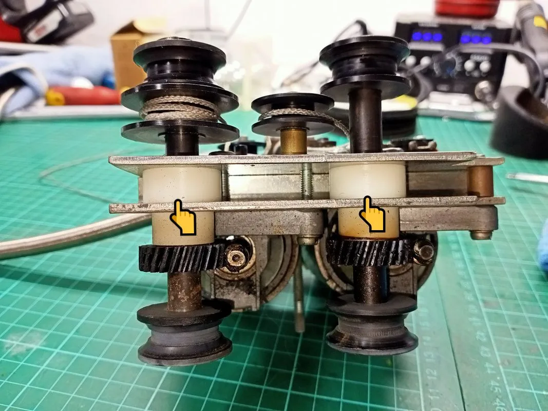
Top down view of the drive shaft bearings onto which the clips for the top flap attach.


U clips installed on the shafts. Unfortunately, they are too high.
I searched for other styles of clips which would fit a little better but had no luck. I'm sure there are some out there that would sit a little lower, but I haven't found them yet. In the end, I stuck the flap down with some strong double-sided mounting tape (Bunnings). There is no pressure on this flap during normal operation so sticking it down is just fine.
New metal flap installed.


Side view of the new metal flap, showing the mounting tape.
There was another part that needed fabrication. The very right side of the gantry has a support plate (rail lock plate) which slides under the rails. Mine was missing. I grabbed the same part from my other Skilltester, and cut a new one out of the same steel sheet. This plate has a couple of bends and some bolt holes, too. I cut the plate a little too small overall, but it still fits correctly onto the gantry so we are all good.
New rail lock bracket (left) compared to an original (right).
New rail lock bracket installed on gantry.

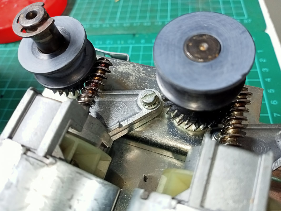
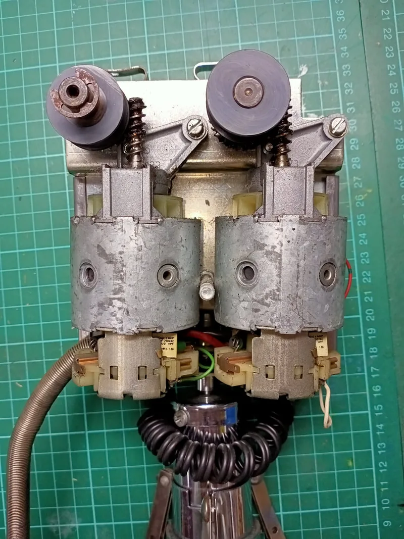
Otherwise, the crane assembly got a general tear-down and service. The entire assembly was cleaned, drive belts were checked for wear, and grease was applied to the motor worm gears (Supercheap). There were no major problems revealed during the service, so everything went back together with the original parts.

Left-right motor and crane motor worm gears. Dry and dirty!

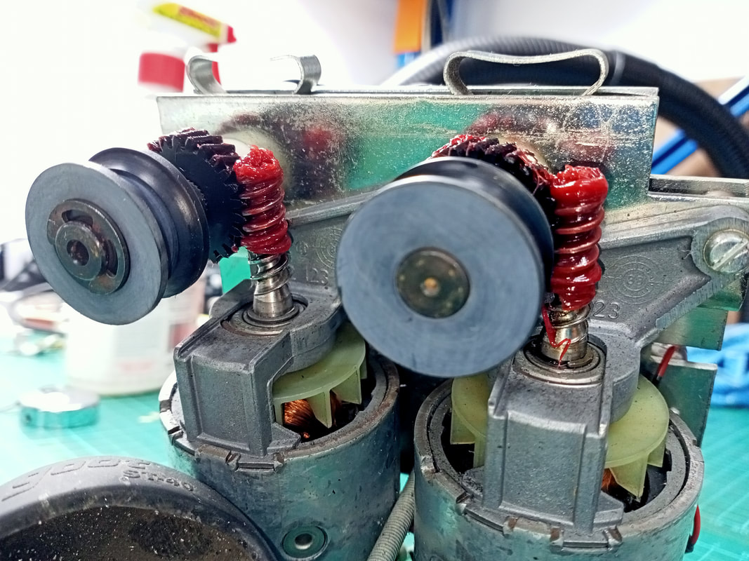
Worm gears now lubed up with grease.
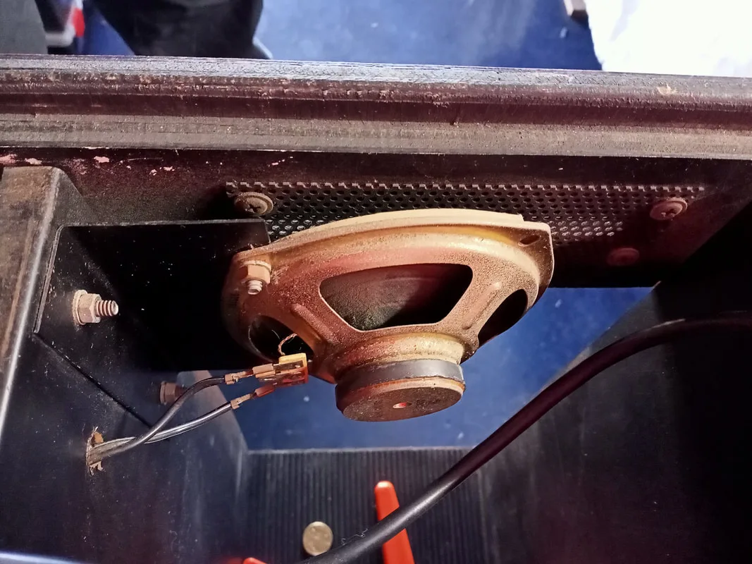
Original speaker mounting position in the centre of the cabinet.


New mounting position... behind the massive gaping hole.
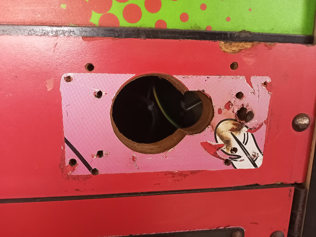
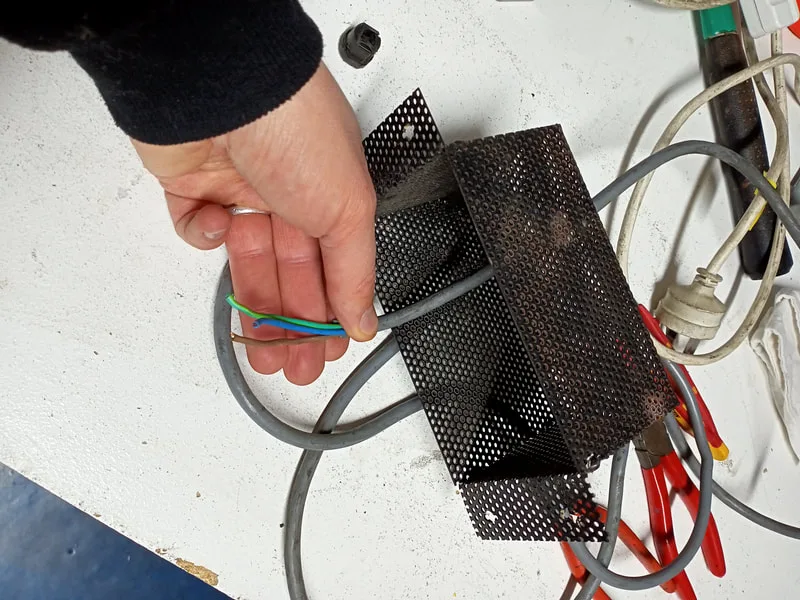
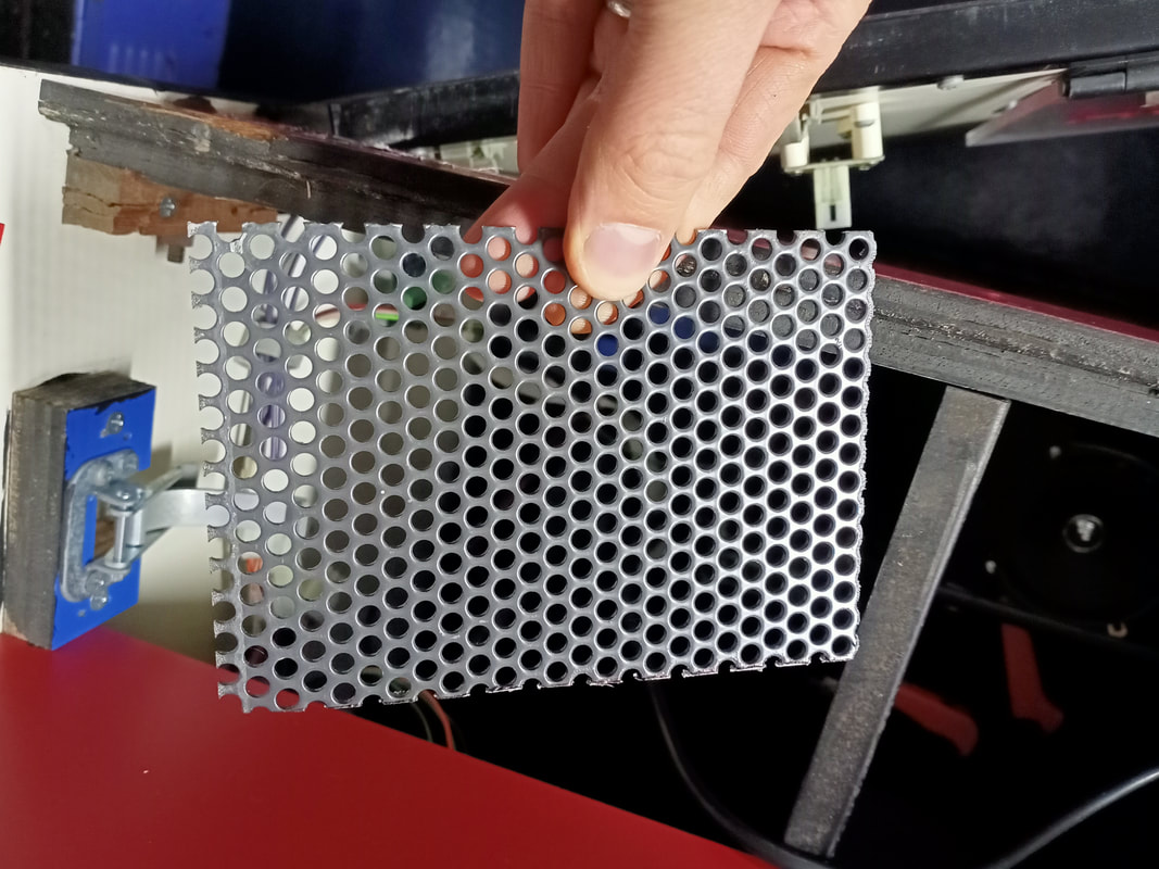
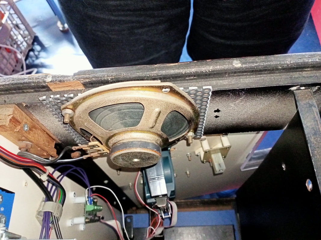
The front of this timber panel was already Swiss cheese with the number of holes drilled into it, so I was able to use two existing holes to screw the speaker to the panel. I cut a small metal grille from some scrap metal mesh to protect the speaker. The cut-out also had some old Plucka Duck decals around it. It looked to me like there was a panel covering the decal and the hole, but the panel was long gone, and was no longer necessary as the speaker was in this position now. I peeled these old decals off as they were pretty ratty. Maybe if I can be bothered one day, I will fill in all of the extra holes and paint them. But for now, the metal grille covers up all of the holes and protects the interior.

Metal grille cut to size to cover the speaker hole.
New speaker location.
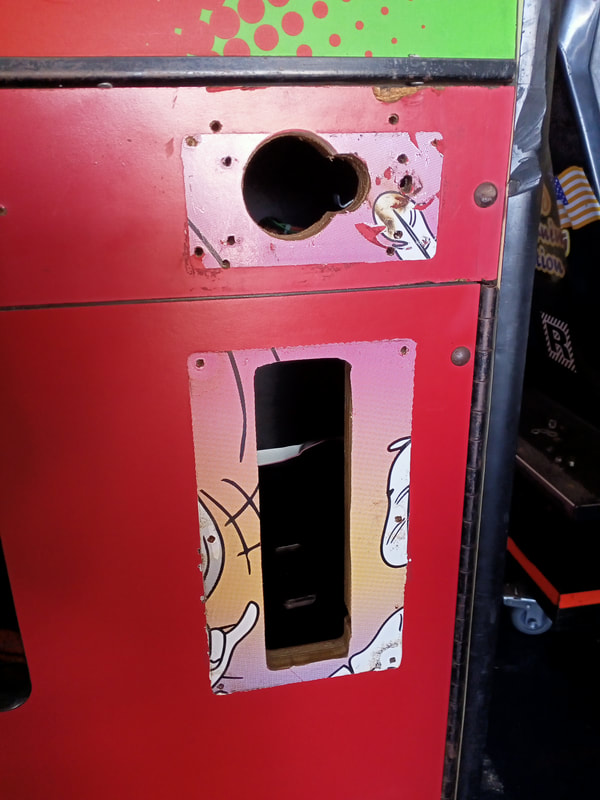
Coin door with black metal panel covering the original coin mechanism slot.

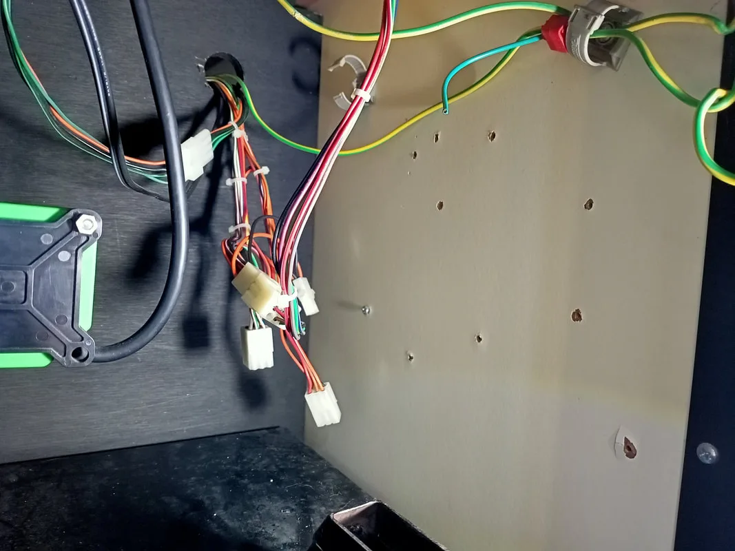
Wiring harnesses hanging around at the rear of the coinbox area.

Based on the Sentinel coin board on the pull-out tray, I deduced that the game was originally set up to use a Sentinel coin mechanism. That would also explain the data cable which I found hanging out of the rear of the machine when I first got it. Sentinel coin mechanisms have Ethernet ports, so you can plug in a data cable and access audit information directly from the coin mechanism if the game doesn't have that capability.
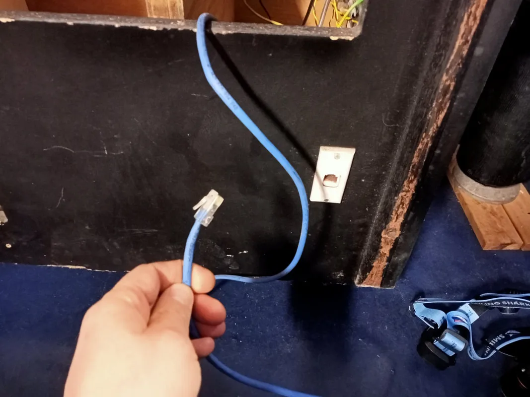
Ethernet cable found shoved in the rear of the cabinet for the original Sentinel coin mechanism.

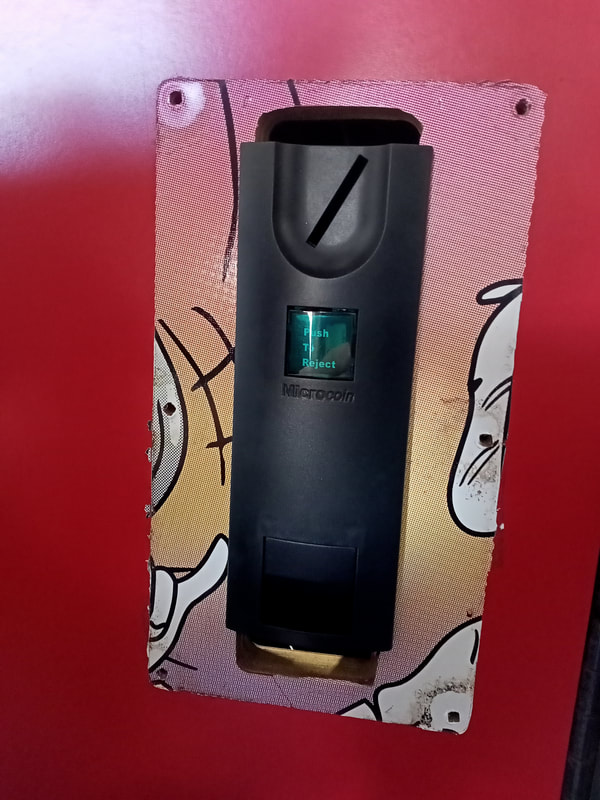
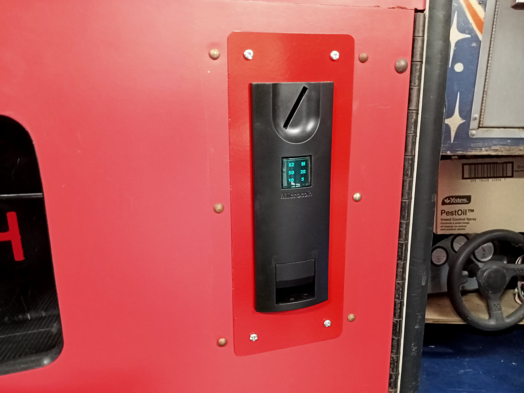
I had a spare Sentinel mechanism, but no way to mount it to the faceplate. These mechanisms have mounting tabs on the front edge, which slot into holes on the faceplate that hold them in place. I rummaged around in my coin mechanisms box and found a solution. I had an original Microcoin faceplate, which I could use with one of the spare Microcoin mechanisms I had. Perfect! I removed the metal panel on the coin door, and tested the faceplate for fitment. It had juuust enough clearance to slide into the slot. Lucky! When I removed the metal plate from the door I also noticed that there were more Plucka Duck decals hidden behind it. The evidence was certainly pretty strong that this was once a Plucka Duck game!

Coin door after removal of the metal plate.
Testing the Microcoin faceplate for fitment. Just fits!
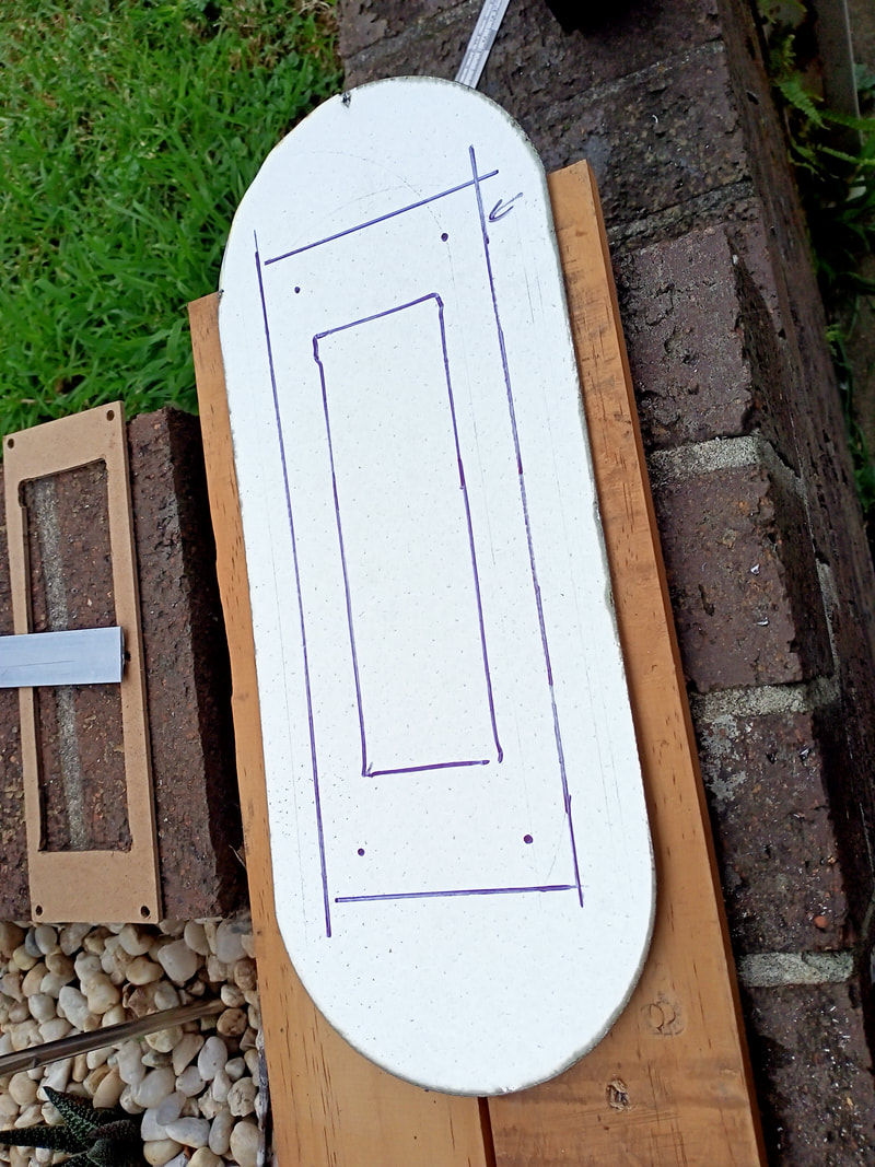
I could simply install a few nuts on the rear of the faceplate to secure it to the door. However, there were some gaps above and below the faceplate that were big enough for people to stick their fingers into, or, snatch coins before they fell into the coin box. These had to be plugged. I decided to cut a new metal adapter panel to cover the hole, and then cut a slot in the panel which I could insert the Microcoin faceplate through. Simple enough! I had some scrap galvanized steel left over from another project, which would be perfect for this job. I cut it to size with an angle grinder, and then held it on the coin door so I could drill out the mounting holes for the screws.

Marking the metal out prior to cutting.
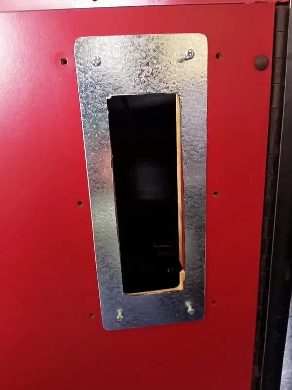
Mounted to coin door with screw holes cut.

Looking good so far! The next step was to make it look a bit more presentable. I painted it with some red Rust Guard paint (Bunnings), which turned out to be a reasonable match to the red laminate on the cabinet. Nice!
Coin faceplate and metal adapter plate installed and painted.
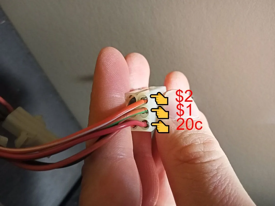
I had a spare Microcoin QL coin mechanism which fit straight into the faceplate (that's the advantage of matching manufacturer mechanisms and faceplates!). Now I just needed to figure out how to wire it up. The QL mechanism interfaces with a small interface board via ribbon cable. I just needed to connect the interface board to the game's wiring harness. Without any reference photos or documentation, I had to do some educated guesswork on which connectors were for what. I found one six-pin connector which looked promising. It had a black wire (ground), orange wire (12 volts), and three other wires. These were orange-white, orange-green and red.
The advantage of older cabinets such as this, is that they were usually designed to use mechanical coin mechanisms which simply closed a switch in order to register a coin. The coin switch would simply short one of the coin lines to ground. Each coin denomination would have a separate coin switch on a separate coin mechanism. So, by grounding each of the three wires on this connector and watching what they registered as on the credit display, I figured out what each of them were for. Orange-white registered as $2. Orange-green as $1. Red was 20c.
The QL coin mechanisms use an in-built accumulator to tally up inserted coins until they reach a set value, at which point the mechanism will issue a credit pulse. This coin mechanisms had an accumulation value of $1, so it would issue a credit pulse when $1 was inserted into the mechanism. This meant I had to connect the orange-green wire to the interface board, so the accumulation value of the coin mechanism would match with what the game was expecting. If the accumulation value of the coin mechanism was $2, for example, then I would connect the orange-white wire instead. Simply terminate the appropriate wire into the "ACC" terminal on the interface board. The interface board also needs connections to ground and 12 volts. As these are all supplied by the same connector, I made up a small wiring harness to connect the interface board to the original connector so it was nice and neat. The Microcoin faceplate also had two wires for a small LED to light up the pricing labels. These also got wired into the 12 volt and ground terminals.
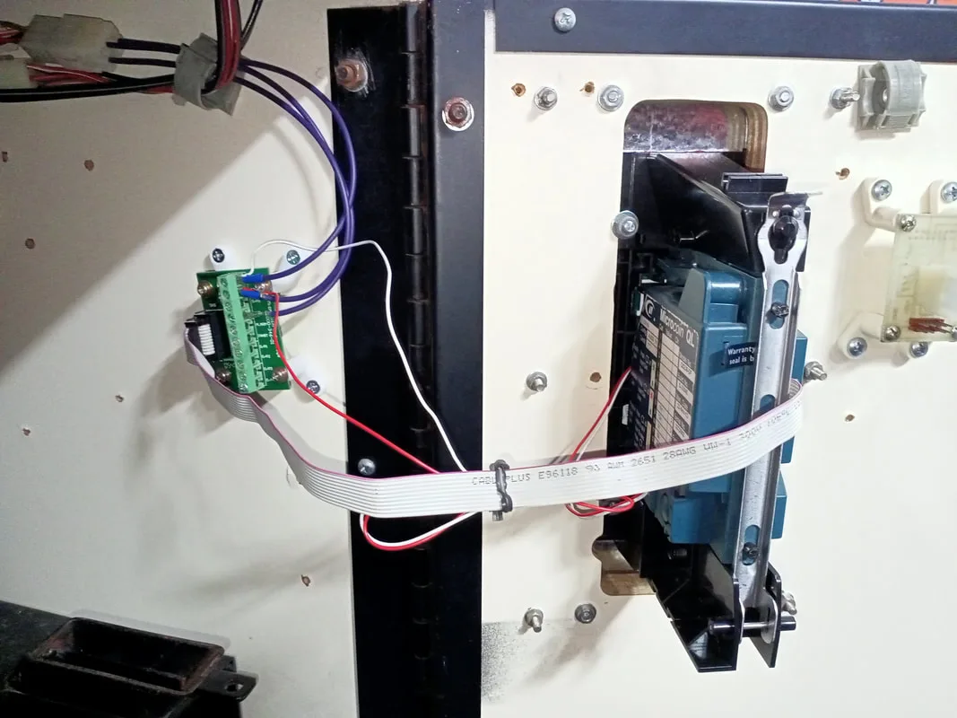
Coin mechanism and interface board installed.


New wiring harness (right) which interfaces with the original coin mechanism harness (left)
There is another consideration when it comes to game pricing. When enough money is inserted into the coin mechanism for it to issue a credit to the game, the game will light up the credit display with the amount of money inserted, as well as the number of "credits" remaining. These "credits" are better described as "plays" as they refer to the number of tries the player has to win a prize. Each turn decrements the number of credits by one, until none remain. I'll refer to these "credits" as "plays" to reduce confusion.
Now, we can adjust how many plays a player gets by fiddling around with the coin mechanism accumulation values. But there is a more precise way to do this. The CPU board contains a number of DIP switches which allow you to select how many plays are awarded for each $1 inserted into the machine (or whatever value your coin mechanism will issue a credit pulse at). Without a manual there was no way to tell what DIP switch settings would do what, so I began a process of trial-and-error to determine what the switches would do. For reference, my original DIP switch settings had all switches ON except for switch 2.
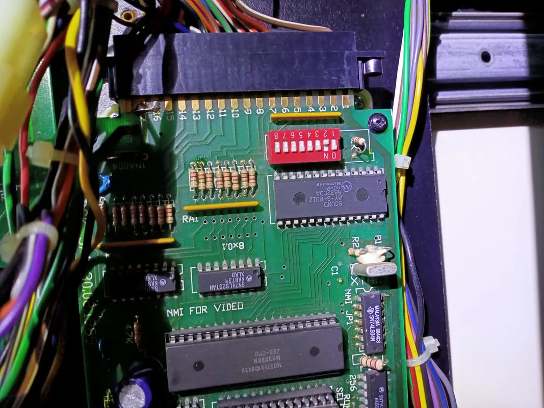
DIP switch bank on the CPU board.

The tables below show the results of that testing. I could set the machine to award between 3 and 6 plays per credit/coin. It appears that only switches 1-3 have any real effect on credit values.
|
All switches ON except for... |
Credit value |
|
1 |
$1 = 6 plays |
|
2 |
$1 = 4 plays |
|
3 |
$1 = 5 plays |
|
4 |
$1 = 6 plays |
|
5 |
$1 = 6 plays |
|
6 |
$1 = 6 plays |
|
7 |
$1 = 6 plays |
|
8 |
$1 = 6 plays |
|
All switches OFF except for... |
Credit value |
|
1 |
$1 = 3 plays |
|
2 |
$1 = 5 plays |
|
3 |
$1 = 4 plays |
|
4 |
$1 = 3 plays |
|
5 |
$1 = 3 plays |
|
6 |
$1 = 3 plays |
|
7 |
$1 = 3 plays |
|
8 |
$1 = 3 plays |
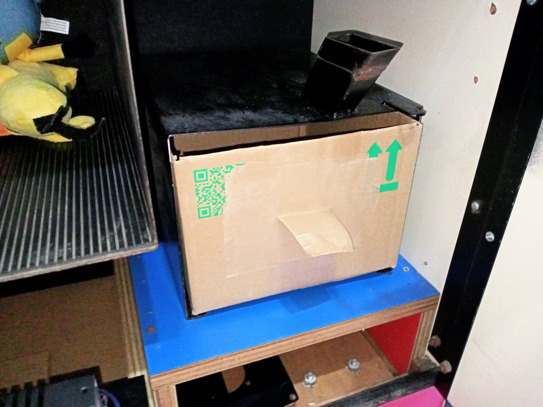
Of course there was one final piece to the coin operation puzzle. The coin box! This cabinet didn't have one at all. I thought about fabricating one from scratch, but this seems like far too much effort for just a simple coin box. Strangely, the coin box for the Type 2 skill tester is a different size to the Type 1 skill tester, so I couldn't just swap one in from my Type 1 machine. A cardboard box delivered by the courier the day before turned out to be the perfect fit!

Makeshift cardboard box coin box!
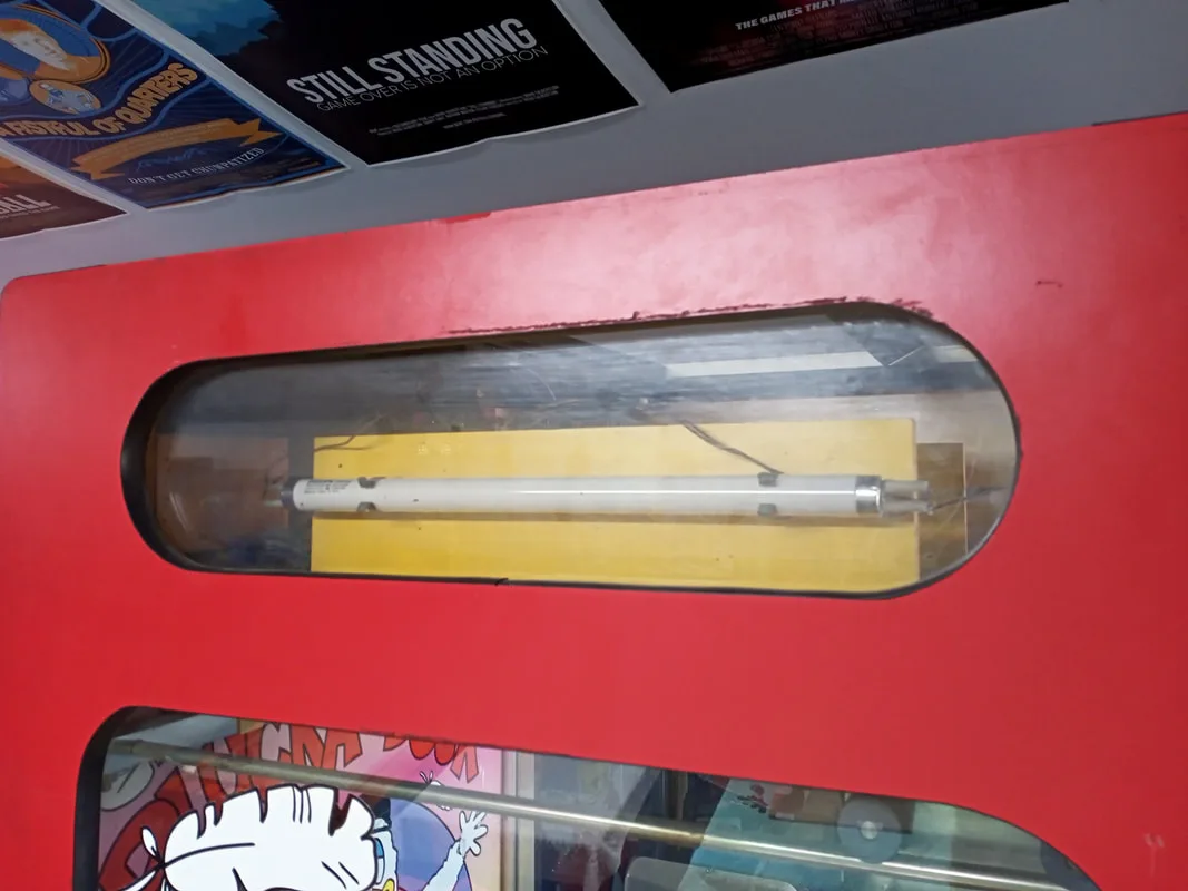
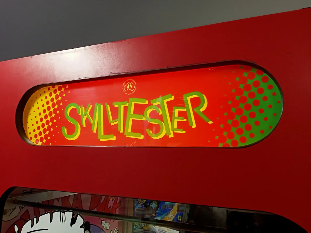
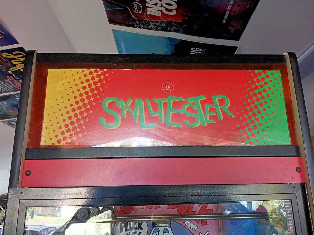
Front view of the makeshift marquee.
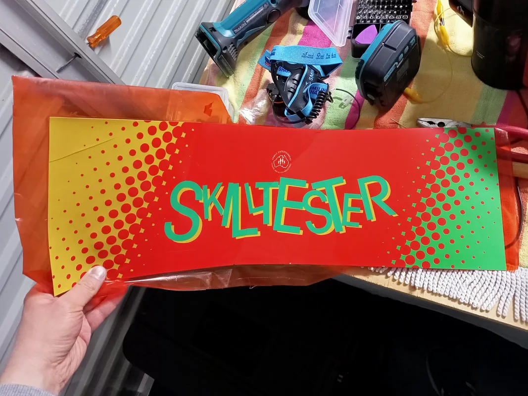
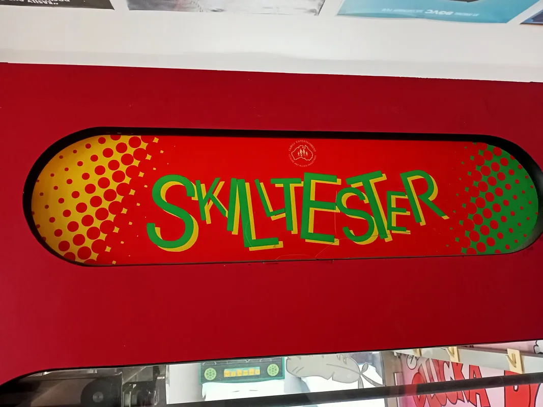
Side marquee plastic stuck to contact film.

Obviously this didn't look great, so I set out to create a replacement. I discovered when working on my previous skill tester that getting an original neon sign reproduced would be possible, but very costly (over $1000!). So that was out of the question. I started brainstorming some other ideas.
My first idea was to recreate the original neon using LED flex neon tubes. These things are everywhere now in place of real neon because they are so much cheaper. They certainly don't have the same glow as a neon tube, but they do look quite good and are much simpler to power (5 volts instead of 5,000!).
You can grab a clear sheet of polycarbonate, cut to size (any plastic supply shop can do this), and simply glue some LED flex tubing (AliExpress) onto the plastic in the shape of the letters you want. But I was a bit lazy on the day I decided to tackle this project, so I looked to see if I could outsource this to one of the many custom LED neon shops that sell on AliExpress. Many of them submitted quotes in the realm of $100 USD, with the cheapest being $63 USD (ex. GST). Not bad! I think they would have looked OK based on the preliminary designs I was sent, but I started to wonder if there was a more interesting way to do it.

Preliminary design of the LED light to mimic the original neon tube.

I thought about current-model skill testers and how bright and flashy they were. So naturally I thought about using some LED light strips to light up the marquee area using different lighting programs and effects. Fiona even suggested creating some kind of infinity mirror effect, which would have looked cool but would have been tricky to pull off. While looking at options for LED strips to buy I stumbled across a huge number of LED dot matrix panels designed for shop and car windows to display advertising. These would be perfect! It makes the sign dynamic and can be as colourful as you want it.
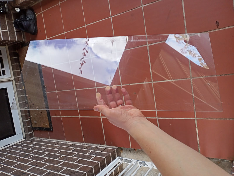
Using measurements from the clear plastic panel, which polished up quite well, I managed to find a panel (AliExpress) that was just the right width (16x96 pixels). By sticking one panel on top of another, I could pretty much fill the entire space available in the marquee area. Then, I could use the top panel to display the word "SKILL" and the bottom panel to display the word "TESTER". They would work in sync as a single sign.

Clear plastic sheet, previously used in the front marquee, after a good polish.
When the display panels arrived I got to work preparing the marquee. The front face of the panels is layered with a gummy conformal coating. It's not adhesive, but it allows the panel to be suctioned onto a non-porous piece of plastic or glass. I simply stuck both displays to one side of the plastic sheet. There is a fairly thick border on the top and bottom edge of the displays where there are no pixels. The problem with this is the panels are slightly too tall when installed edge-to-edge to fit between the metal trim pieces at the top and bottom edges of the marquee area. I had to overlap the panels slightly, so that the bottom edge of the upper panel sat on top of the upper edge of the bottom panel... if that makes sense! This looks a little odd because you can see the air gaps where the panel doesn't contact the plastic in front of it. But the effect is not too noticeable when the sign is on.

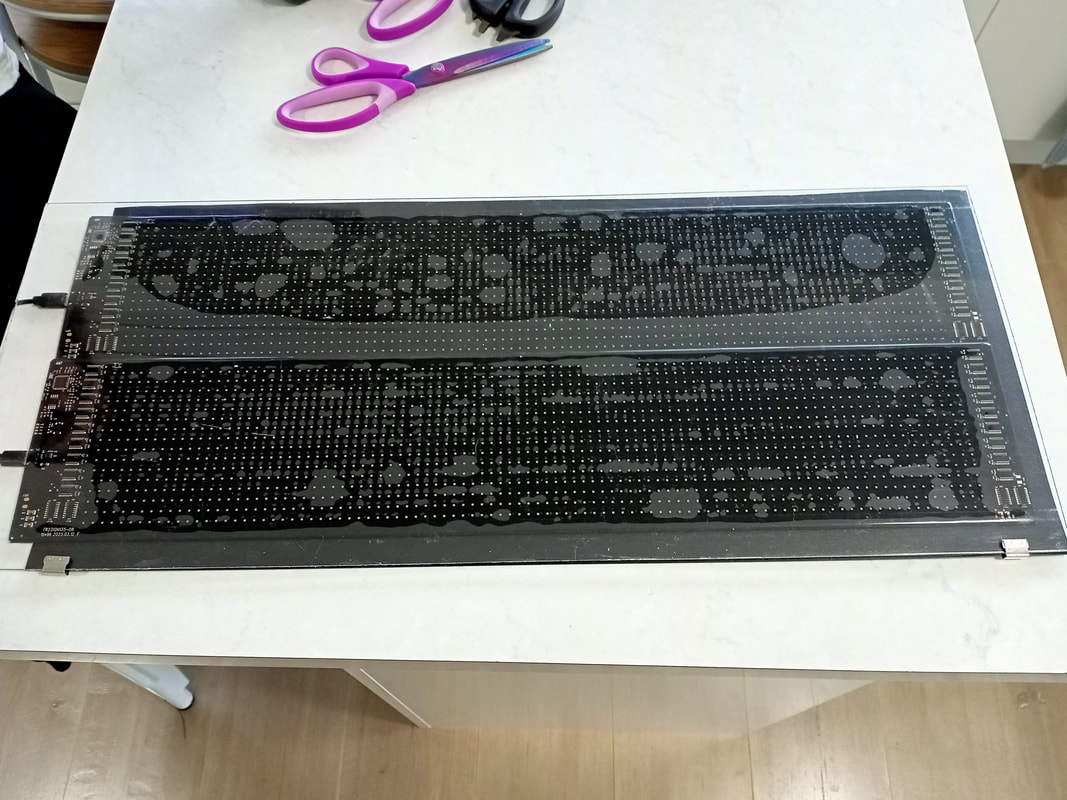
Next, I had to install some kind of backing behind the display panels. This would give them some support and shield any light from shining around the panels. I used some black polypropylene sheets (Officeworks) cut to size. I also installed strips of this plastic in front of the displays on the left and right edges, to cover up the electronic components that were mounted to the front side of the panel. The main thing they hid was the metal ground plane and USB ports attached to it. The plastic was then secured in place with slide clips (Officeworks) that were wide enough to grasp the polypropylene backing sheet as well as the clear plastic sheet at the front. The tacky nature of the LED panels means that they "stick" to the plastic sheet in front, giving them a "wet" look in some areas. Looks a bit weird when the displays are off, but when they are on you can't really notice it. Some spacers to separate the panels from the plastic would probably fix this, but that was unnecessary in my opinion.
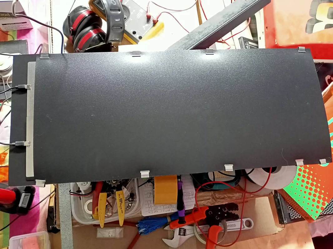
Polypropylene backing sheet installed and clipped into place.


New LED marquee when viewed from the front.
Now I had the marquee structure sorted out, it was time to figure out power. Each display panel was powered by a USB connector and cable (5 volts, 2 amps). I initially thought about installing some small plug-in transformers (connecting them to the distribution box in the lower cabinet) but this was an ugly solution. The first step was to piggyback the USB power cables onto one another, so I could power both displays from a single supply. I stripped some old USB-C cables and installed them into a 0.062" Molex style connector, with the original USB-C plugs going to the displays. The red wire is for 5 volts, and white is for ground.
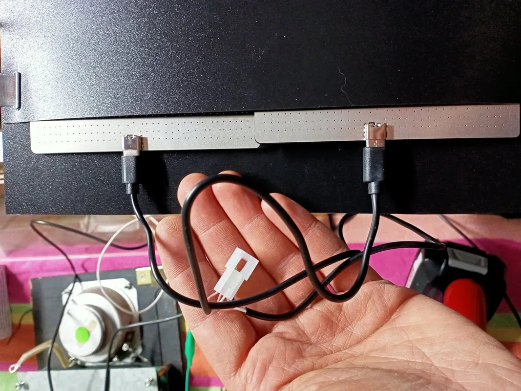
Installing a connector on a piggybacked USB cable.

Now we just need to find a 5 volt power source. As chance would have it, there was a loose connector in the head of the cabinet with black and yellow wires. This was originally connected to a relay, but the relay wasn't connected to anything; the wires attached to it had been cut. With the game on, I probed this connector and found that it was supplying 5 VDC. Awesome! Maybe I can use this connector for the displays? Unfortunately, no. I soon realised that this connector leads to the CPU board, and is supplied 5 volts pretty solidly by the CPU until a prize is dispensed. Then, it oscillates between 5 volts and 0 volts every second for about 10 seconds.
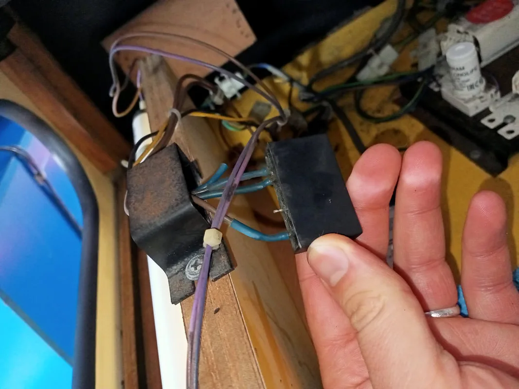
Relay in the head of the cabinet.

So when I initially connected the displays to this connector, I was really confused when they started to turn on and off when I won a prize! Why the hell would they do this? I soon figured out that this connector was originally meant to be connected to a relay board, with multiple relays to switch a 240 volt supply to multiple 240 volt devices. I found a similar board for sale locally (Highway). I'm not sure if this is the exact board that would have been used in this machine, but it is marked as an "LAI Solid State Relay PCB", so maybe! I assume this would have been connected to the neon tube or some of the other lights in the marquee, so they would flash on and off when a prize was won to attract attention. Ultimately, I didn't have the right type of lamps in the marquee to have a use for this board, so I didn't use it. I removed the relay and left the black and yellow wire connector loose in case somebody wants to connect it again in future.
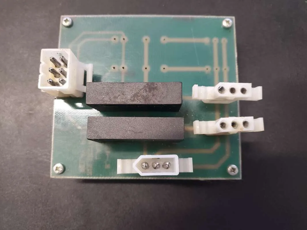
Unknown LAI relay board, component side.

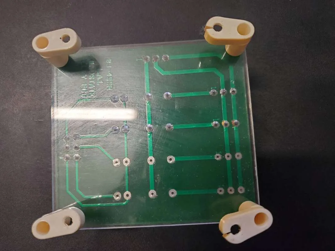
Unknown LAI relay board, solder side.
Instead, I decided to route some new wires through the cabinet all the way from the marquee area to the new power supply. The 5 volt rail on the power supply was a beefy 15 amp supply, so it would be plenty to power the displays and other boards in the machine. Unfortunately this meant snaking the wiring harness through the back wall of the cabinet. I used a makeshift cable feeder made from a long strip of metal to feed the wires down the back wall, and then dressed them neatly onto the main wiring harness leading to the front of the machine.

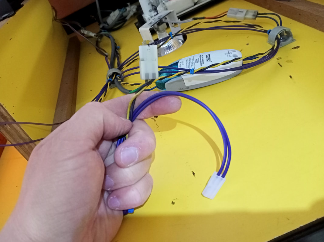
Yellow and black wire connector (top) with my new wiring harness (purple).
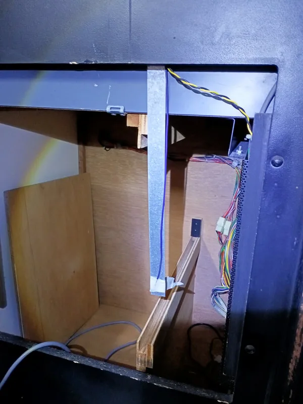
Using a metal strip as a cable feeder at the rear of the machine.

Once the wires were threaded to the front of the machine, I installed some eyelets and bolted them onto the power supply's 5 volt and ground terminals. I turned the game on and off a few times to test the displays. They worked intermittently. The upper display would always turn on, but the lower display seemed to get stuck in a constant reset loop, or it would fail to turn on altogether.
New power wires for the marquee displays (purple wires on right).

After some double checking and fiddling around with my new connectors, I discovered it was a problem with the connector I had installed on the lengths of USB cabling. The USB cable wires were very, very thin with barely any conductor material in them. It was hard to get a perfect crimp with so little conductor material, so the tiny gaps in the crimp were causing intermittent connectivity issues. I couldn't go to a larger terminal pin or connector because the wires were simply too small. And unfortunately I didn't have anything smaller.
The solution was to load the crimp pins in the connector with solder. Normally I don't advise doing this, as it can lead to cracking and poor connections. However in this case the solder was needed to carry the maximum current necessary for the displays to function, and solder was the best way to fill the gaps in the crimp terminal.
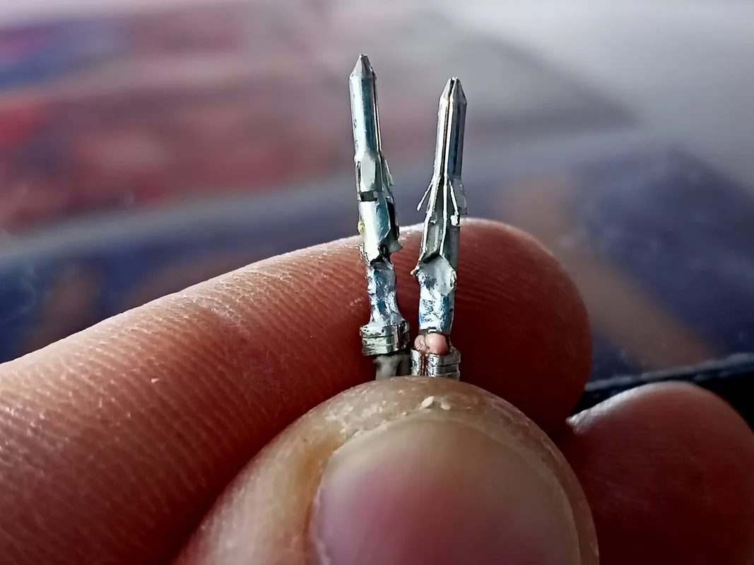
Crimp terminals loaded with solder.

Once I did this, both displays turned on every time and stayed lit without issues. Making them display pure white images on all of the pixels is the best way to stress test LED displays, and I did this several times and the displays didn't miss a beat. So the power issue was fixed. Next time I might use some different USB connectors with heavier gauge wire, but for now they're working well.

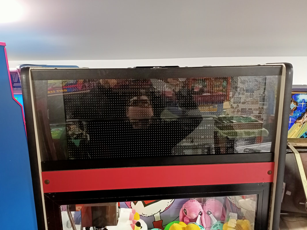
New LED display marquee in action.
I'm pretty happy with how this new marquee turned out. The LED panels come with an app which connects to them via Bluetooth. You can them broadcast messages, pictures, and all sorts of animations to them. Since I was using two displays, I had to use animations which would display the "SKILL" and "TESTER" text for the same amount of time. Some scrolling animations don't work well because "TESTER" takes much longer to scroll through than "SKILL". This causes the two displays to go out of sync, and the animations get mismatched. So there was a bit of experimenting involved to figure out which ones worked best.

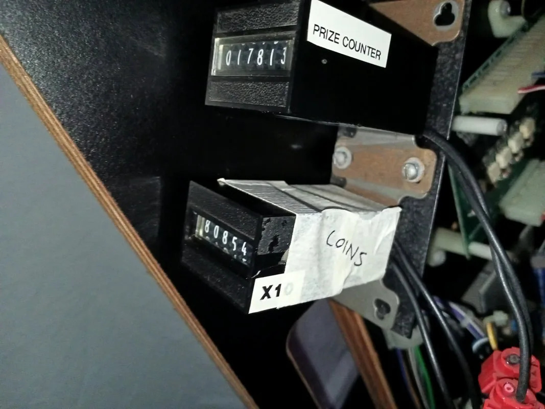
Coin counter on the front door with loose wires.
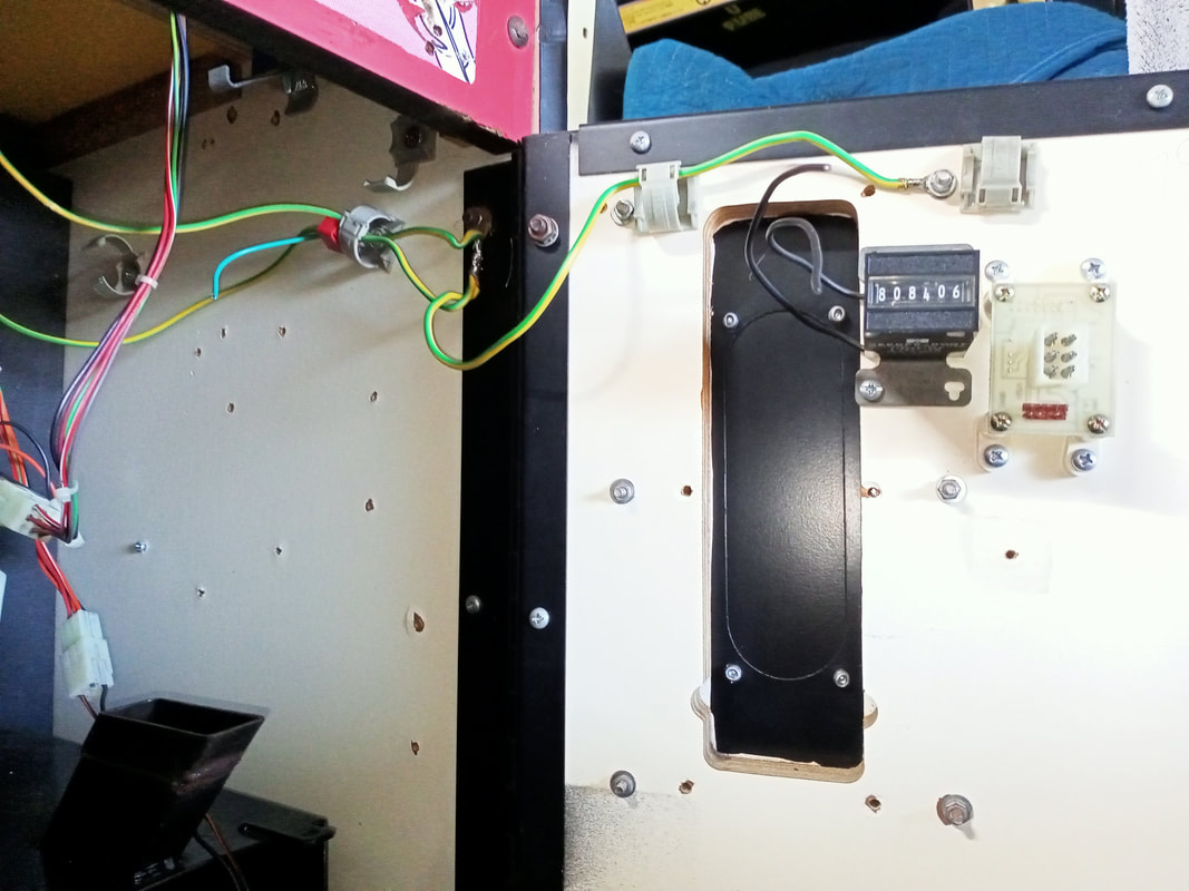
The first thing to note is that the coin counter was displaying 808,406. The counter increments 1 count for every 10 cents inserted. So that means this machine has brought in $80,840 in income (assuming the coin counter has always been working properly). Insane!
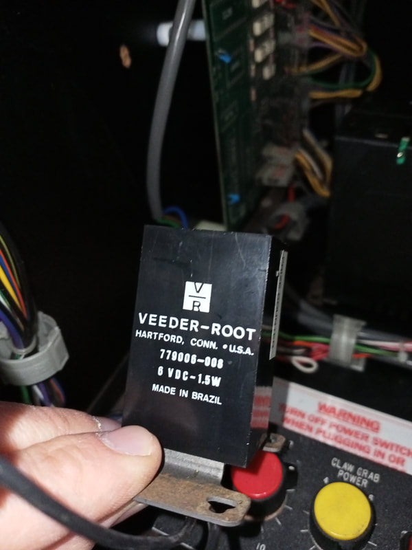
The next thing to note? There were three loose wires dangling around the prize counter (mounted to the pull-out shelf). I would hazard a guess that this is where the coin counter was meant to go. The two black wires were ground, and the yellow wire was 5 volts. I moved the counter to the same bracket as the prize counter, and installed some connectors so it could be wired in. But even after I did this, it still didn't work! All I got was a faint clicking sound whenever the counter was meant to increment. Normally this would be a case of "throw it out and replace it", but these coin counters are unusual. They are 6 volt counters, which I couldn't easily source. Moreover, most of the readily available coin counters out there run on 12 volts, which I didn't have. So, the only option is repair. Let's tear into it.
View showing the specifications of the coin counter.
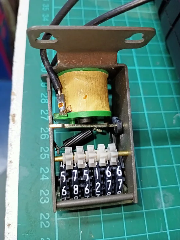
View of the internal components within the counter.
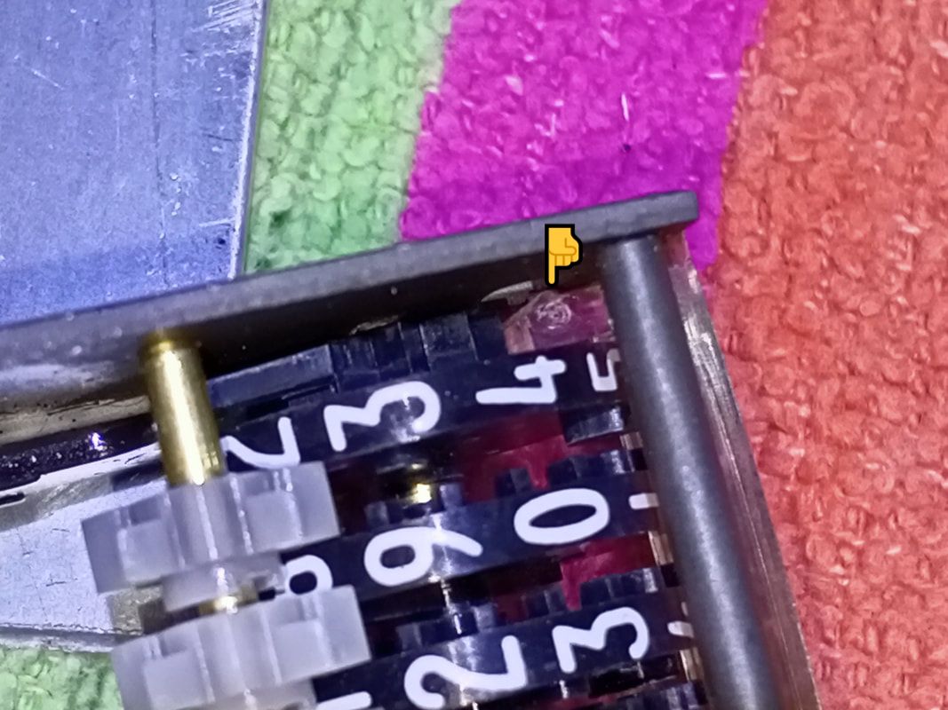
Unfortunately, these units are not designed to be serviceable, so you need to crack open the housing to get to the innards. What's inside is very simple. A small solenoid which engages to pull on an armature. This armature then increments the lowest value digit, and when this digit gets to 9, it flips the next digit based on the position of an interlocking gear. Simple, neat, electromechanical design. I love it! I realised that, when activating the armature manually, the rotation of the digit dials was being blocked by the clear plastic window at the front of the device. The window "tab" on one side had shifted out of its mounting hole. Pushing it back into place released the tension it had on the dial, and the digits could move freely again. That was it! After that, I did my best at repairing the plastic housing with what I had available (tape), but it doesn't quite look as good as the original. At least it works though!
View of the plastic tab which was blocking the digit dial from rotating.
Repaired coin counter installed and working.
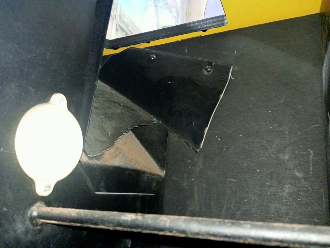
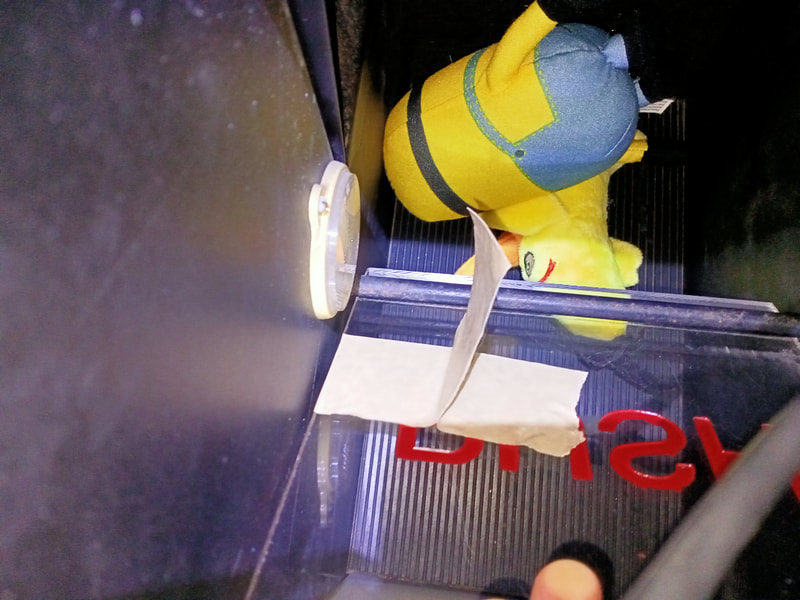
Remains of the plastic prize chute. Reflector for the prize sensor is visible at right.
You can't buy a new plastic prize chute, and making one up was more trouble than it was worth. I considered moving the position of the sensor, but this too was more trouble than I thought it was worth. I settled on an even easier solution. When a prize is won, someone will reach into the chute to retrieve it. So why not make the door trigger the prize dispensing sensor? That way, when the door is opened to grab a prize, the sensor will be tripped, regardless of how the prize falls into the chute.
Now, is it possible for someone to trigger the sensor even if a prize hasn't been won? Yes, but that's no big deal. The prize counter will just go up and the game will play a sound. But on the flip side, it will trigger more reliably than it currently does when a prize is won, which will generate more interest in the game and more excitement for the player. So, it's a good solution in my mind. All I did was attach a small piece of tape to the rear of the prize chute door, bent at an angle so that it would pass in front of the beam reflector when the door was fully open. Nice and simple!
Nice and simple prize sensor beam interruptor.
Reassembly
The only real disassembly and reassembly on these units is related to the crane and gantry. The disassembly didn't get too hardcore on this machine, so the photos below just show basic component layouts which should assist you should you need to do any further disassembly.

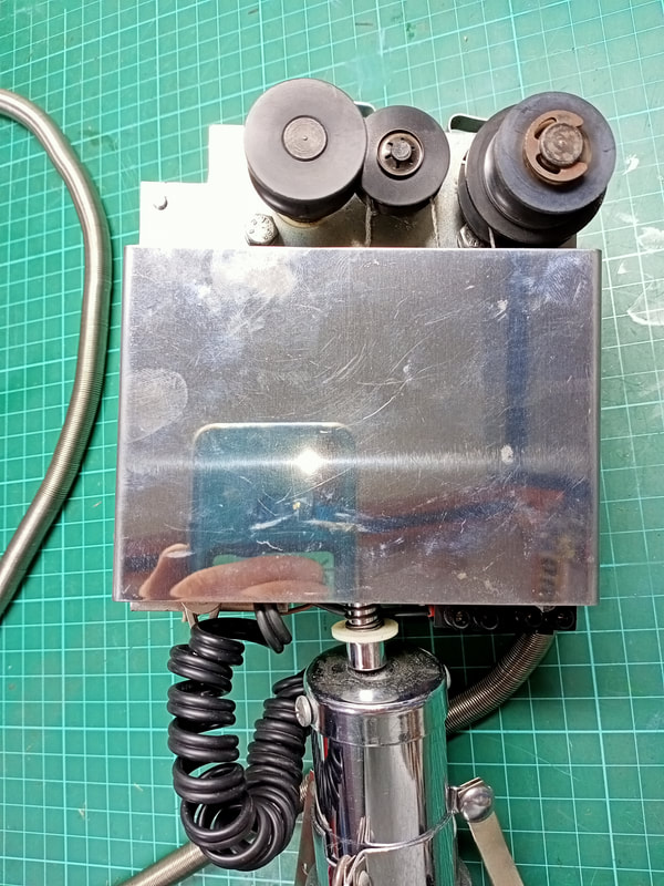
Crane assembly, front view with cover on.
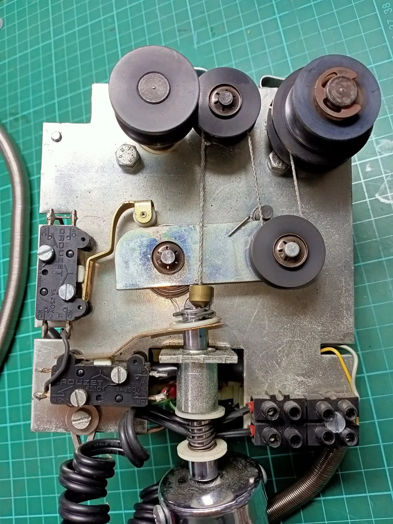
Crane assembly, front view with cover off.

Crane assembly, rear view with cover on.

Crane assembly, rear view with cover off.

Of course the major attraction of any Skilltester or claw machine is the prize bed! This machine didn't come with any prizes already in it, so I had to source my own. There are plenty of suppliers for plush toys and other novelties which you can use to load your machine up. A quick review of any issue of the AMOA magazine will have plenty of sponsors advertising this kind of stuff. I decided to stick with plush toys as prizes as they were a good size and shape for these claws to grab. I found most of the prices listed by distributors to be quite high for basic plush toys. I began looking on AliExpress and Temu, and found that Temu actually has a massive selection of plush toys. Yes, quality is a bit low on some of them, but most of them appeared to be pretty well made. You need to search around for cheaper ones, or take advantage of the the special deals which allow you to get a certain selection of items for cheaper than normal prices. I ended up getting an assortment of Pokemon, Disney and emoji plush for between $2-5 per toy. All up, I spent about $100 and got enough toys to fill the prize bed to a minimum level. I'd say another $100 would fill it up nicely to the top. I imagine getting a wholesale deal on plush from Alibaba or a similar platform would be the way to go if you need to fill up a fleet of claw machines. The toys turned out to be a mixture of good and poor quality. But even the poor quality ones were funny enough to be a novelty.

Prize bed filled with plush toys from Temu.

This was a good machine to tear apart and service after the previous Type 1 Skilltester. While some of the knowledge from the Type 1 cabinet came in handy when servicing this one, the new board set was an interesting challenge. I haven't had any failures occur with this board yet, but it looks fairly straightforward so I'm confident I can get it up and going again if it does fail in the future. Otherwise, it was a nice challenge to develop a topper from scratch, and fun to fill the cabinet with toys! I have actually found a site to place this machine in a friend's comic book shop. It will be interesting to see how the machine does in this environment and how much income it generates.
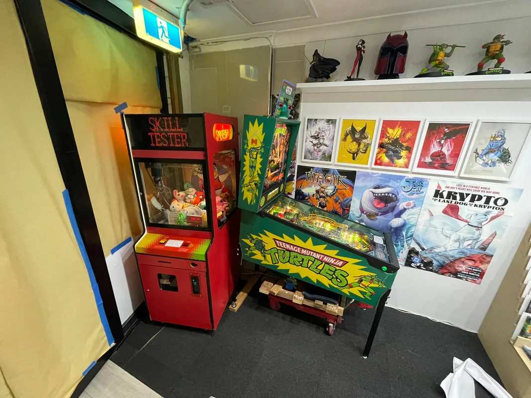
Set up and ready to earn in a comic book shop!
