|
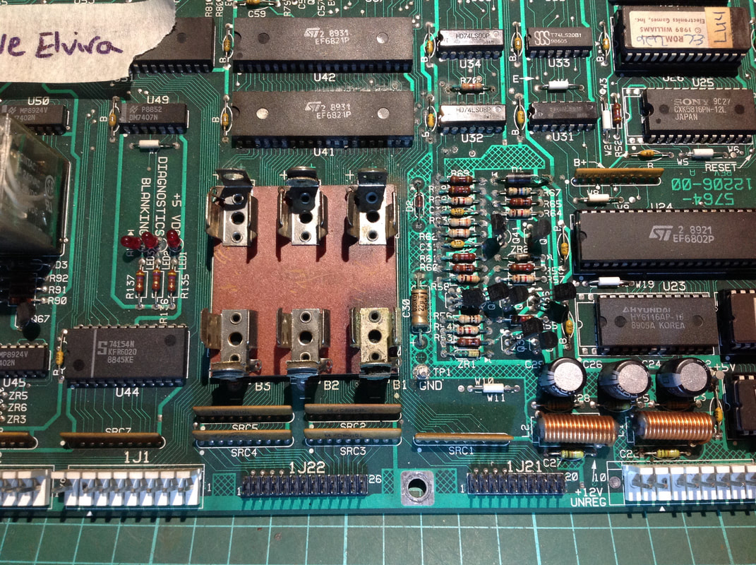
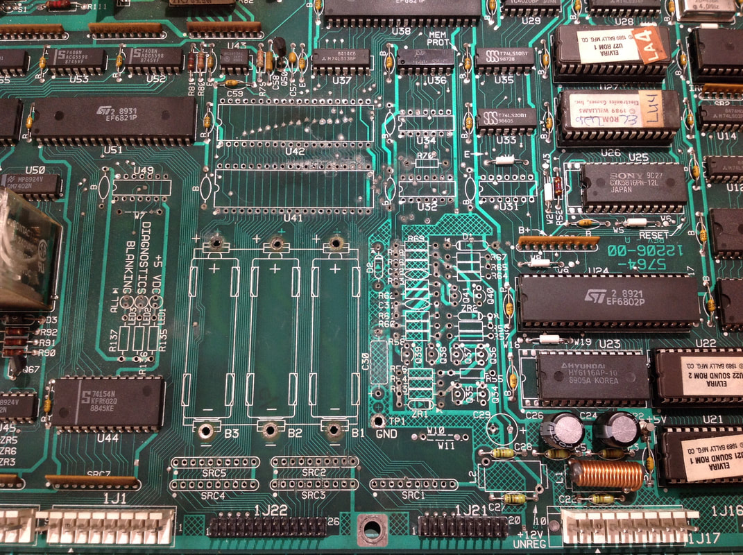
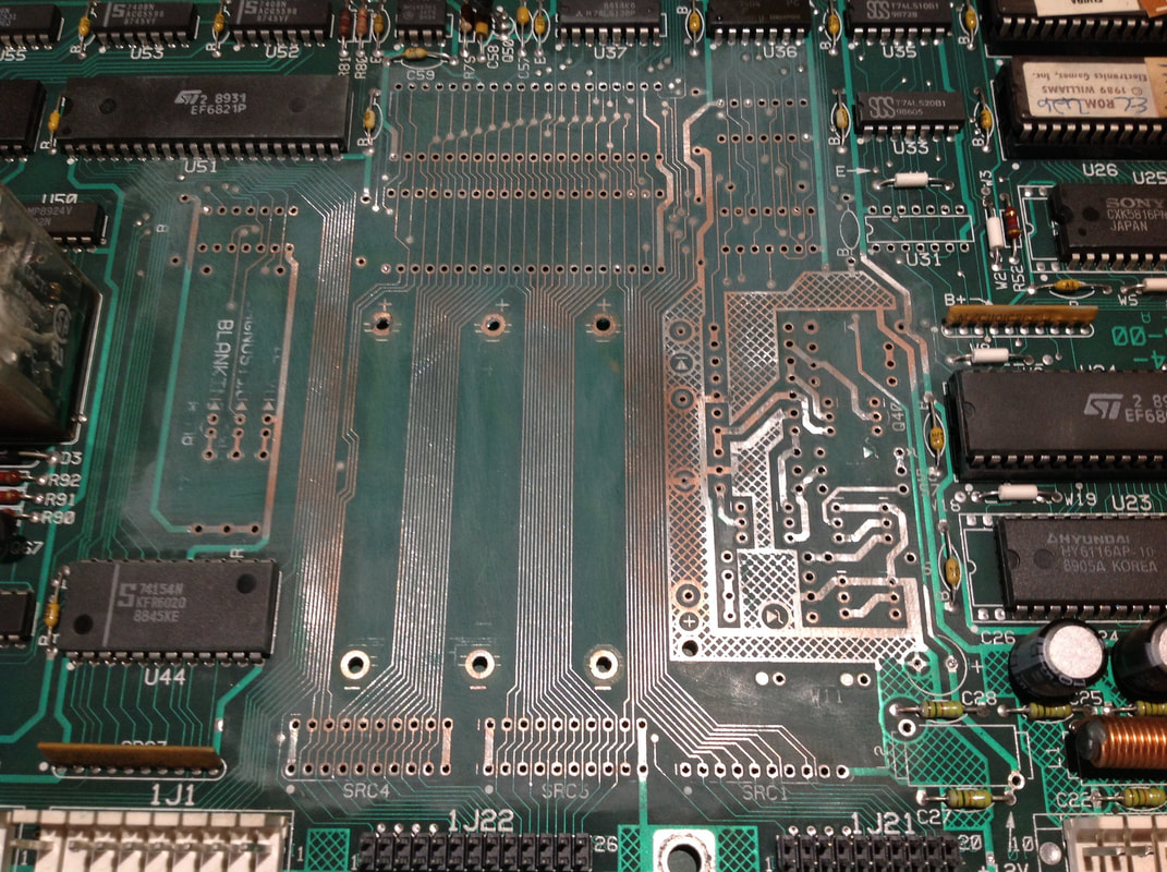
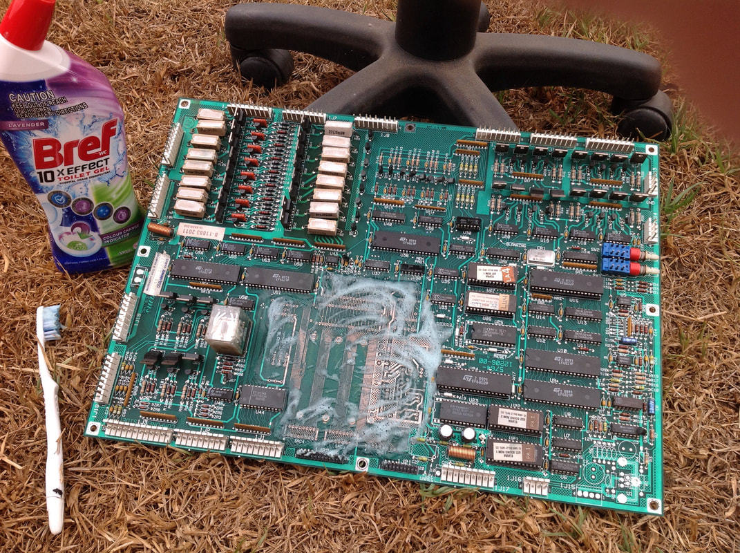
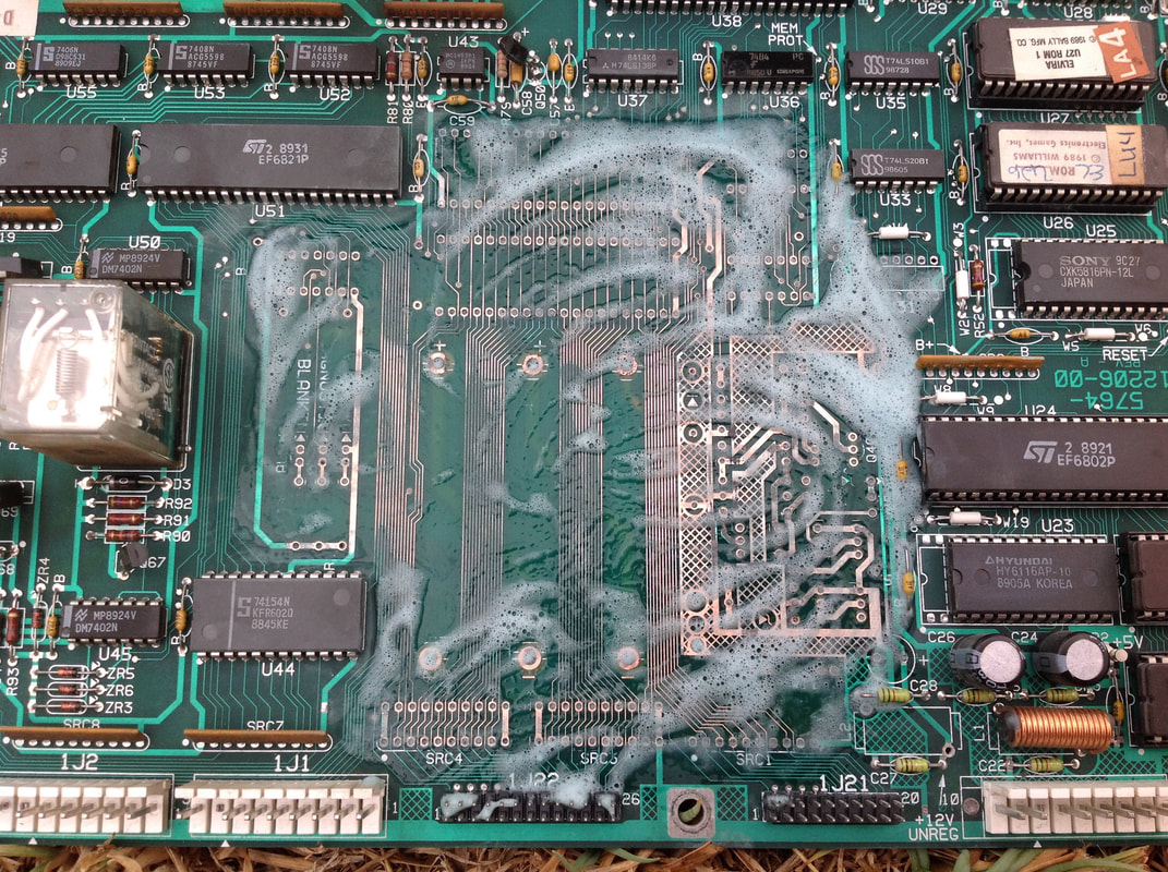
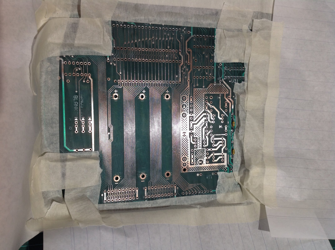
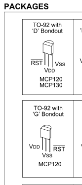
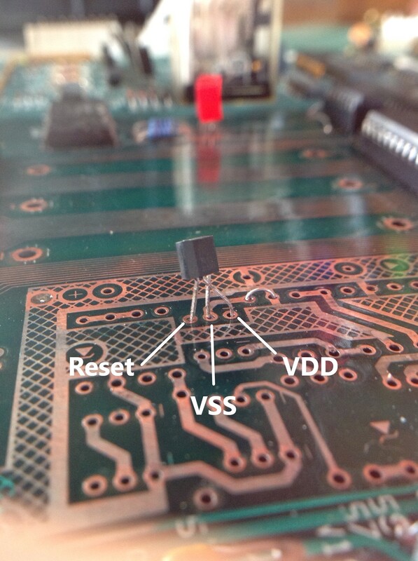
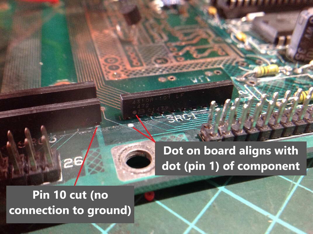
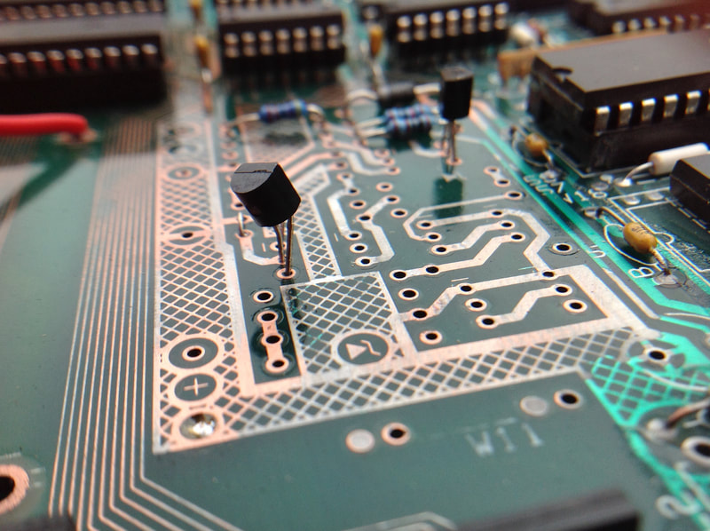
Christmas sure was a good time for pinball repairs! Several weeks ago, a customer advised me that their Elvira and the Party Monsters (Williams, 1989) was no longer working. They had had the game for a long time and it had always played without issue. However, they did note that sometimes it would take several flicks of the power switch for the game to turn on properly. Now, it would not turn on at all. No lights, no sounds; nothing! When they opened the backbox to inspect the game, they found a lot of green electrolyte from badly leaking batteries on the MPU board. Uh oh! This was likely the source of their problems, so they brought the MPU board in to me for repair. Battery corrosion is always a difficult thing to repair, but with replacement MPU boards costing $400 USD not including shipping (up to $650-700 AUD landed), repair is sometimes a more economical option. While it is a daunting task, Pinwiki had a useful step-by-step guide to assist in the repair process. Clay's guide also contains similar information. Terry has a great guide on Pinside, too. Lots of other guides are available, but those three seem to be the most comprehensive. There was significant corrosion around the pins of the battery holder. There was also significant dry electrolyte material to the right of the battery holder, in the "reset" section which is responsible for booting the game. Failure of a part in this section was probable, and intermittent booting issues like the customer experienced previously were probably an early indicator that one of these parts was starting to fail. There was a lot of gunk on these components, so it was no surprise that they were starting to die. Other than that, there was corrosion moving upwards to U41, with various pins on either side of the integrated circuit quite badly affected. Some pins of U42 also showed signs of damage. Adjacent to U42, there were signs of minor corrosion on some of the integrated circuits including U31, U32 and U34. To the left of the battery holder, the diagnostic LEDs were destroyed, and U49 appeared to be at the limit of corrosion creep. Some light corrosion was visible on the SRCs below the battery holder also. All of the above components had to be removed. Battery fluid makes solder difficult to heat and work with, but luckily the traces on the rear of the board were all in good condition. The desoldeing station make quick work of most of the components. Those pins that still refused to budge were all removed with a soldering iron and tweezers. After removal of all stray component legs, and a quick clean of the board to remove the loose debris, it was time to mechanically remove any trace of the alkali. I like to use a combination of sandpaper (about 220 grit) and a fibreglass pen for finer details. Scrub the board thoroughly with the sandpaper. You want to see the conductors under the affected solder mask nice and shiny. The silkscreened part numbers will disappear, so make sure you either have good photos or clear schematics to help you put parts back in the right spot. Now it was time to chemically neutralise the battery alkali. Original wisdom has always been to abate battery alkali with vinegar as it has a low pH (up to 3). I stumbled across a thread on Pinside which discussed using a stronger acid for this purpose as vinegar sometimes doesn't have the right amount of "kick". While the battery corrosion on this board was not totally out of control, I prefer to use as strong a neutralising agent as possible to ensure that the corrosion won't rear its ugly head again. Better safe than sorry! So, I headed down to Coles to see if they had anything appropriate. Americans have much stronger acids in their toilet cleaners (some which hydrochloric acid). You can't seem to get anything that strong in Australian stores, so I had to settle for some Bref toilet cleaner, which contains formic acid (pH 2.3). I massaged it into the board with a toothbrush and got some good foamy action going. The traces on System 11 boards an be quite delicate but thankfully none of them had been severed by advancing corrosion. Some people advise using a wire brush but I think this is too severe, particularly on the fine traces below the battery holder on this board. The next step was to clean the board off. I used water (copious amounts of it) and followed up with isopropyl alcohol (Jaycar) to help dry things out. Integrated circuits such as U44 got some water under them, so I used an air compressor to blast all of the remaining water and alcohol out from under them. Be careful of the relay on this board, as water ingress will damage it! After rinsing, I let the board sit in the heat of the day for a few hours to make sure all moisture was 100% gone. It helps to do this in summer; I left it outside on a 35 degree day and it was as dry as a bone. By this point the board was as clean as it was going to get. The alkali was concentrated mainly around the reset circuitry, with some clumps around the through holes. The sandpaper and chemical treatment did a good job at getting rid of it. I think this treatment regime worked well for this board, and I'll be surprised if the corrosion ever returns. The board needs to be sealed so that atmospheric oxygen doesn't corrode the exposed copper conductors. I used a simple circuit board lacquer (Jaycar) which was easy to apply as an aerosol. I masked off the unaffected areas with tape and paper so the lacquer wouldn't get into any places it shouldn't. The lacquer was touch-dry in 15 minutes or so, but I left it to cure fully overnight. Once it was dry, it was time for the new parts to be installed. Areas where the lacquer covered through holes could be easily pushed through with component leads so that they could be soldered on the solder side of the board. Plus, the lacquer can be soldered through, so you don't need to worry about soldering a lacquered board. Acquiring parts was one of the most laborious parts of this job. It was made somewhat easier because on System 11 boards, the reset circuitry can be replaced with a single reset generator component, rather than the fifteen or so components that are originally on the board. Pinwiki describes the operation of the reset generator. This is a very handy component for repairing corroded boards, as it reduces the amount of soldering you have to do significantly. Unfortunately I couldn't find the recommended MCP120-460GI/TO generator easily. There were some on eBay, but I wanted to get them from a better source. I found a similar reset generator with a slightly different part number: MCP120-450DI/TO (RS Components). The main difference in these part numbers is the GI and DI suffixes. These refer to the pinouts of the component, which are actually quite different. If installing a DI/TO version, you will need to install the component in the opposite direction (reset pin towards top of board), and bend two of the component legs so they swap positions (VSS pin in centre, VDD pin towards bottom of board). The other difference in part number (450 vs 460) refers to the voltage at which the reset generator will 'trip' and reset. For this purpose, the difference is negligible. The next part which required a bit of modification was the SIP resistor banks at the top of the board, above the battery holder. Pinwiki describes the issue with these; they are now obsolete and unobtainable. However, they can be replaced with more commonly available components. You can use equivalent parts such as a 4.7k ohm, 9-pin, 8-resistor network (RS Components). These need to be installed so that pin 10 on the board is left vacant. I purchased some 10-pin variants (RS Components), which meant that I had to cut the lead from the tenth pin so that it wouldn't make contact with the board. When installing these resistor networks, make sure you align pin 1 on the board (indicated by a silkscreened dot) with the dot marking on the resistor network. This is pin 1; the common pin. The rest of the parts were relatively easy to get. I have included a parts list below for the specific components I needed for this repair. I haven't included the sockets I used, or the new diagnostic LEDs, as these were already in my toolbox. Not all repairs will be this extensive (i.e. replacement of microprocessors and other integrated circuits), and others yet may be larger, requiring more parts. So adjust as necessary! The parts required for the reset section are in bold. Don't forget that, if using AA batteries as the power source, D2 also needs to be replaced.
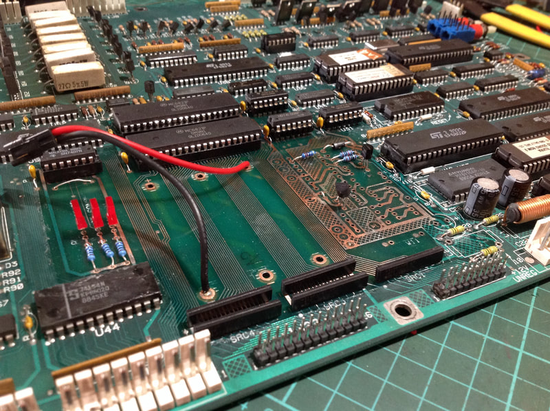
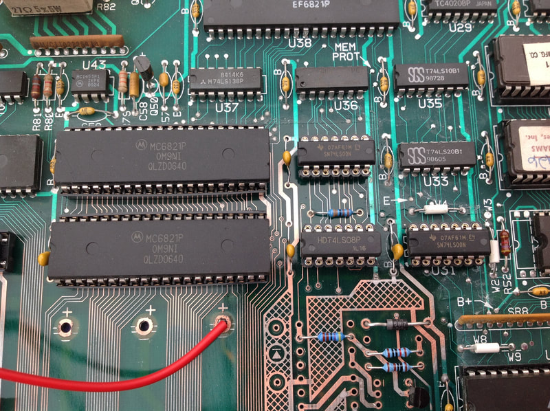
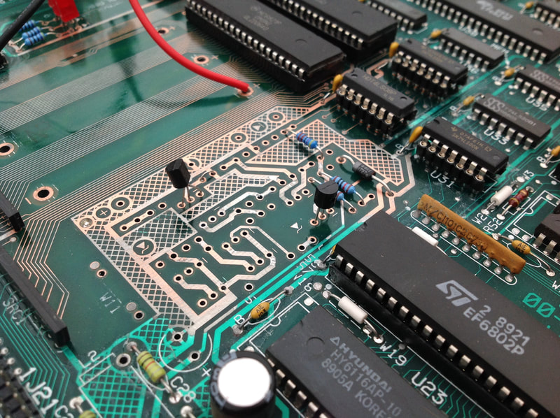
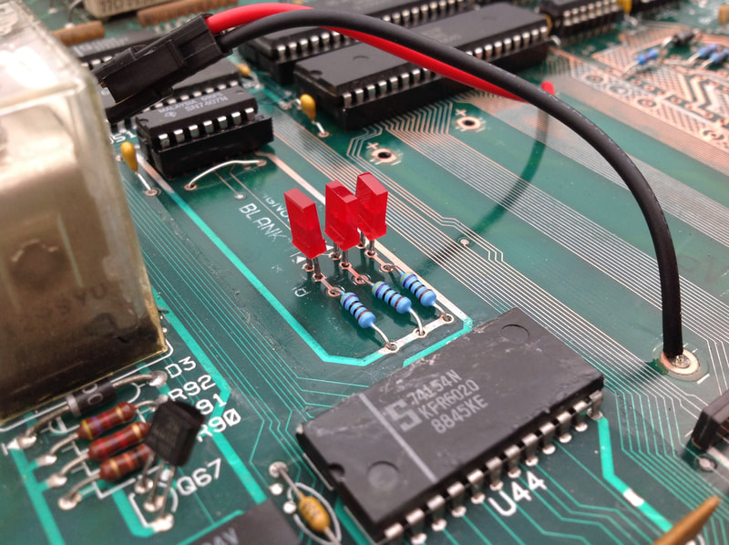
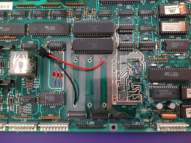
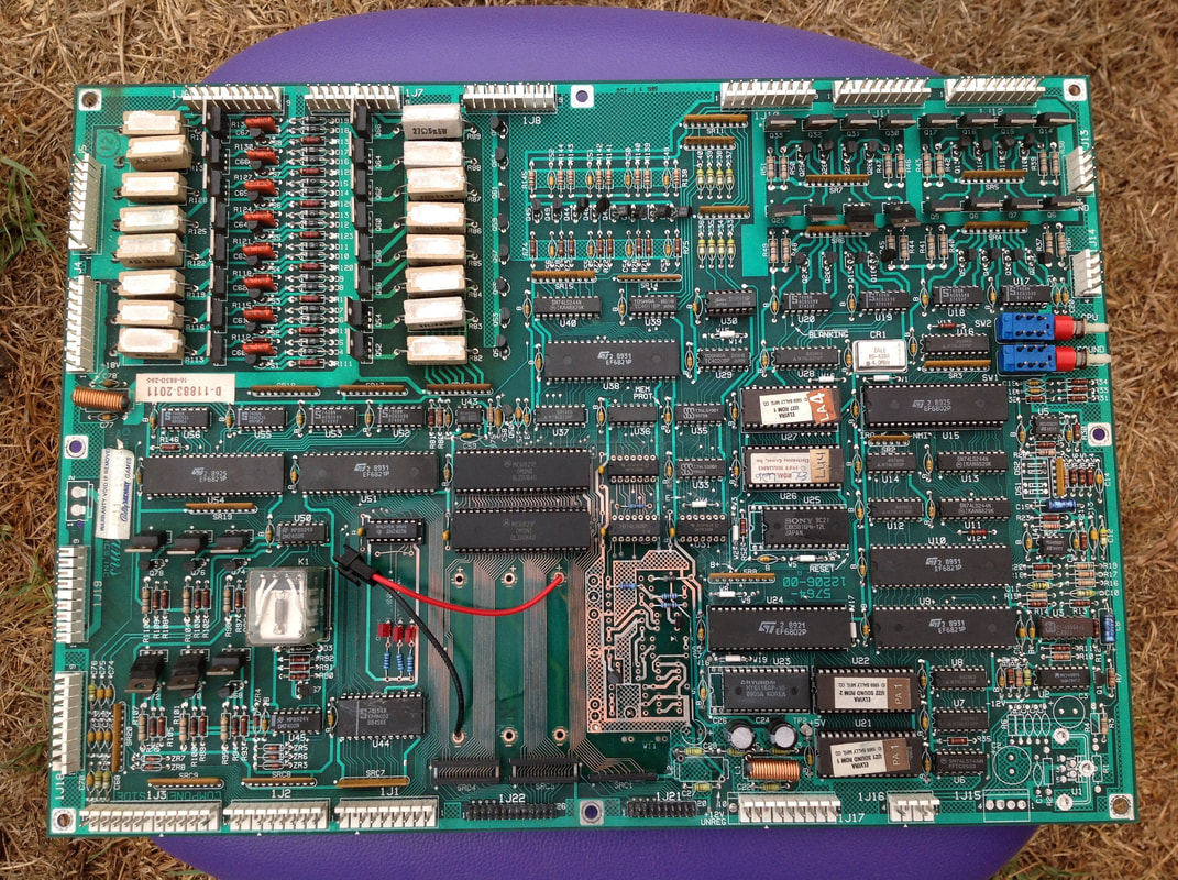
As for the component that originally caused all of this damage - the battery - I decided to install a remote AA battery pack. I would have preferred to use a coin battery holder, but unfortunately there are too many components too close to the battery area to mount a coin battery holder flush with the board. So, a remote battery pack was a good compromise. I used a small inline connector so the battery could be disconnected if necessary. Then it was time to finally test the board and see whether all of my hard work would finally pay off. The board only needs 5 volts to test the reset circuitry and boot. 12 volts is required for sound but is not necessary for the board to boot. You can hook up your external power supply to header 1J17 at the top of the board, with ground at pins 1-3, and 5 volts at pins 4-6. And, hey presto, the board booted up! The 5v and the blanking LEDs light up and stay on, while the diagnostics LED flashes on and off continuously to indicate a successful boot. Woohoo! It's always good to know that all the time you spent working on a board like this has finally been worth it. The customer was very happy to have his board working again, and reported that his Elvira and the Party Monsters worked once he plugged the board back in! A note regarding the below photos. As I was using a remote battery pack, I also needed to reinstall a diode at D2. However, I forgot to install this diode until after the pictures were taken. So, just image it's there for now!
2 Comments
George Thornburg
20/12/2021 11:08:47 am
Hi. I'm Trying to find a company/person that can take a look at my Gameplans Sharpshooter MPY board.
Reply
Leave a Reply. |
About
Here you will find logs of our pinball and arcade machine restorations, repairs, discussion about general pinball and arcade topics, as well as recounts of our random pinball adventures.
Check back regularly for updates! Blog updates
Archives
May 2024
Categories
All
Donate

Running this website is a hobby for me (just like pinball!). I like being able to show off my restoration work so everyone can learn from it and potentially fix their own machines. If you enjoy reading the site's content or it has been helpful to you, please consider donating to offset some of the website's operating costs. |

 RSS Feed