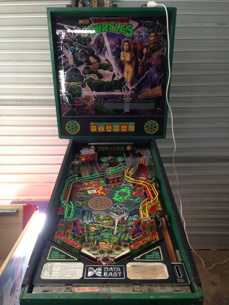
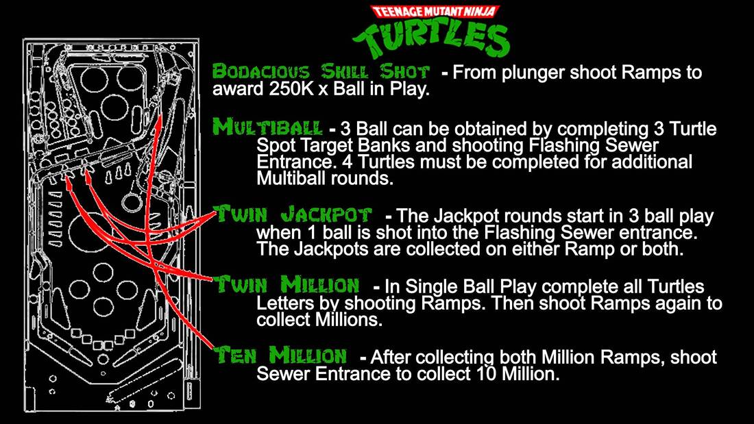
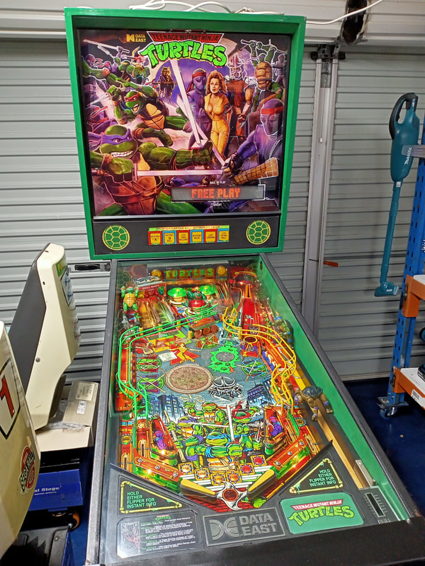
 This restoration was for a customer who had just come into possession of a Teenage Mutant Ninja Turtles (Data East, 1991) pinball machine from a family member who originally wanted to sell it. Luckily, he convinced them not to sell it and instead get it restored. Of course, I was happy to help, and was keen to get some more experience with Data East machines. Early 90s Data East machines are generally not known for their fantastic gameplay, but the games are simple and fun, which is all that was really needed in an arcade in the 1990s. Initial condition report (click on sections below to view details) Cabinet
Good condition overall.
Above playfield
Poor condition overall.
Under playfield
Average condition overall.
Electrical
Poor condition overall.
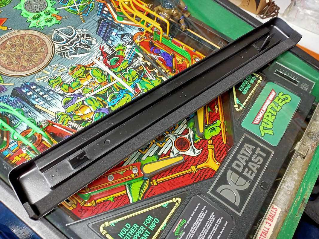
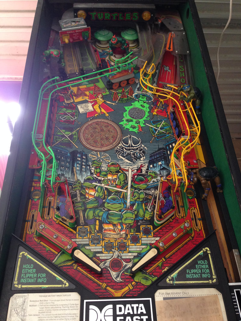
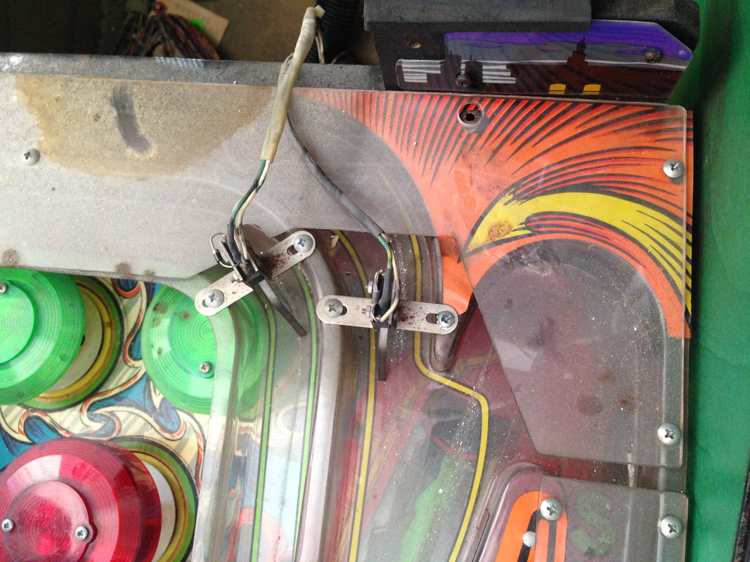
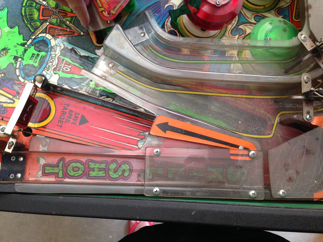
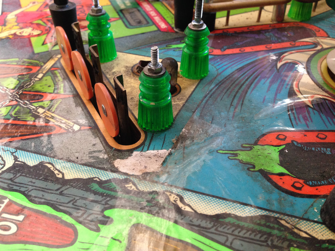
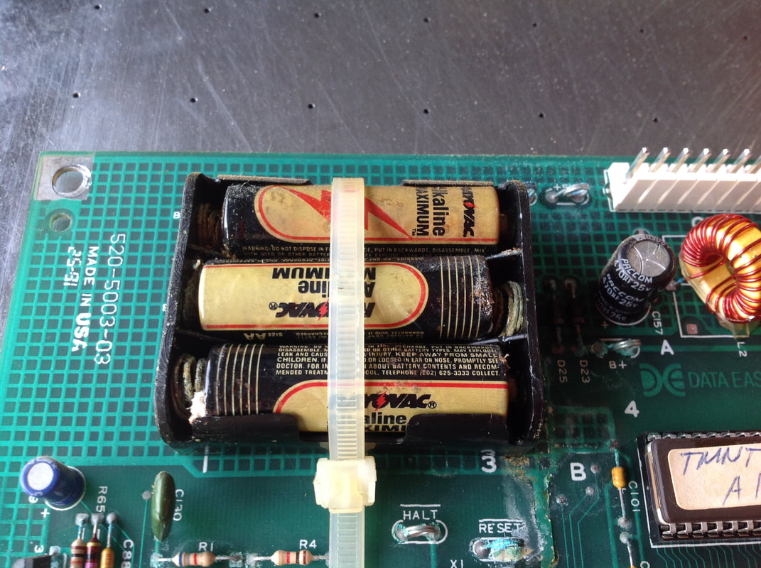
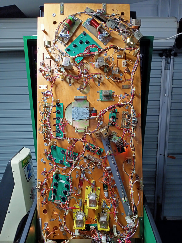
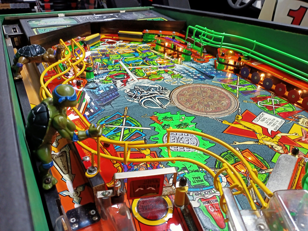
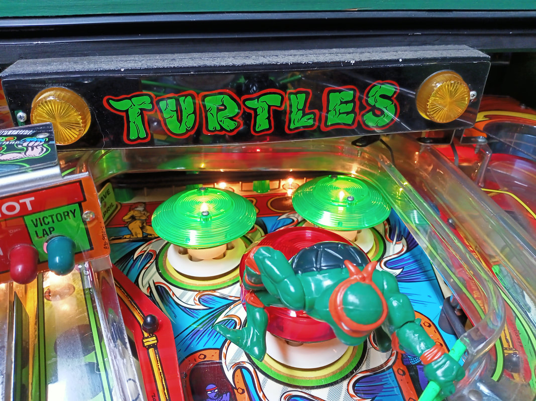
The major issue with this game off the bat was the battery leakage that was evident on the MPU board, which explained why the game was unable to boot. Otherwise, the game was in average condition physically, which wouldn't be too hard to fix up. As the game couldn't boot I wasn't able to test anything in terms of gameplay or mechanical function, but coil plungers seemed to move freely and there was no evidence of any coils having caught fire (always a good sign). The customer didn't want the game fully restored to as-new condition, but wanted it fixed to a point it was playable, and given a quick once-over shop job. So this restoration focused on the electronic issues first, followed by the playfield work. Disassembly Like most early Data East games, Teenage Mutant Ninja Turtles has a pretty simple playfield with just one main plastic ramp, and two wireform ramps connected to it. The rest of the playfield is a single level with one subway (and reportedly the first use of a subway in pinball). So, once the ramps and TURTLES light assembly (which sits above the ramp) are off, the rest of the game is quite easy to take apart. Note that the TURTLES lamp assembly is attached with two metal screws, and you need to undo one flashlamp connector (left side) in order to have enough leeway to move the assembly. Another connector under the playfield is for the TURTLES lamps in the assembly, however I found it easier to leave this connected and simply let the assembly sit in the game cabinet until it was ready to be reinstalled. The wires are long enough to do this without it hanging in mid air. You'll need to disconnect three connectors before taking the main plastic ramp off the playfield. One is for the lamps on the left of the ramp (routed through playfield hole), one is for a single general illumination lamp under the arrow decal (routed through playfield hole), and another is for the two ramp switches (routed over the panel at the rear of playfield). Once disconnected, they can be pulled through the playfield and the ramp can be removed. Removal of the ramp is fiddly, and there are a couple of tricks which make it easier to install. The spinner assembly should be loosened and moved as far leftwards as possible. Otherwise, it sits on top of the ramp entrance, and prevents it from being pulled up. Likewise, Raphael's left foot is positioned directly above the ramp. He blocks it from being pulled up and out, so remove the plastic that holds him in place to make things easier.
Otherwise, there's nothing to take particular care with when disassembling the playfield, apart from the tendency of tee nuts to destroy screw threads when you try to remove them. I found two broken tee nuts on this playfield, which were replaced. Below are some images of disassembly. After disassembly, the game went through my standard restoration process to get it playing and looking like new. During the restoration process, I dealt with a number of issues, described below. Tips & Troubleshooting (click on sections below to view details) Game would not boot up
When turning the game on, the general illumination lamps would light up, lights on the MPU board in the backbox would flicker, and the "Teenage Mutant Ninja Turtles" startup jingle would play through the speakers. But that's all that happened. The display did not turn on, a game could not be started, and the machine seemed to hang in a perpetual half-booted up state.
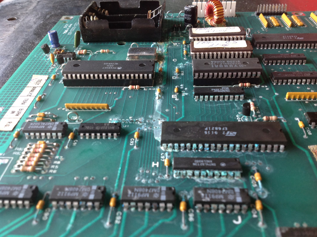
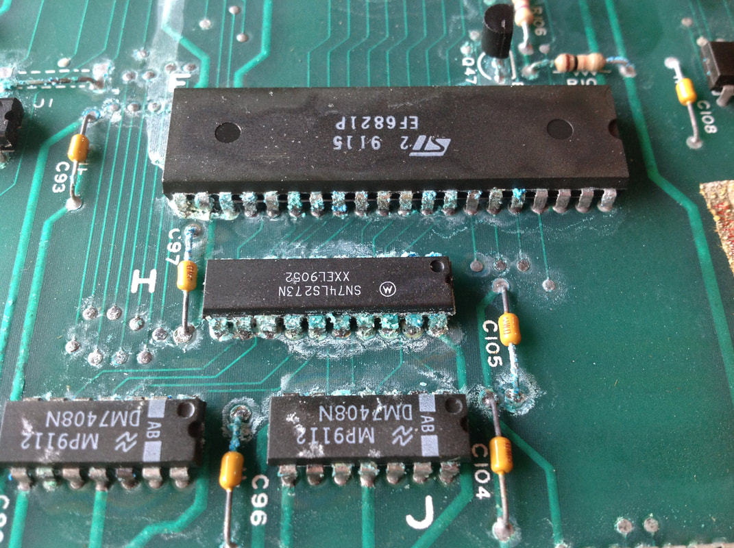
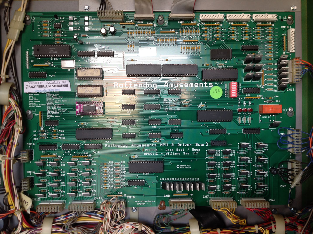
As with any game that has been in storage for a long time, the first thing you need to do is check the condition of the boards in the backbox. Unfortunately, once I checked the MPU board, the problem causing the game not to boot became clear. The PIA led on the MPU stayed lit, whereas it should go out after a second or so according to the normal LED flash sequence listed in the first page of the manual. I looked over towards the 6821 PIA chips on the left side of the board and realised that this entire half of the board was affected by battery alkali leakage. The caustic fluid had dripped all the way down the board to the transistors on the bottom edge. Some images of the damage appear below. The batteries looked to be the original batteries installed at the factory and there was no expiry date or lot number printed on them to determine how old they actually were. After the damage was fully assessed, it was clear that it was not only the 6821 PIA which was affected, but a bunch of other components responsible for the game booting up and running. Unfortunately, with leakage this extensive, the most cost effective fix is to replace the entire board. This board may be repairable but it will never be as reliable as an undamaged board and there is no guarantee that corrosion abatement procedures will be 100% effective. Not to mention, this kind of damage would take at least 10 hours to properly repair. My advice to the customer was to buy a Rottendog replacement board, which he agreed to do. After waiting a week or so for the board, it arrived. The MPU004 board from Rottendog is not plug-and-play for Teenage Mutant Ninja Turtles. This board was purchased sans processor and game ROMs, so these were transferred from the old board and were thankfully in good condition despite the alkali leakage affecting the processor socket. Ninja Turtles does not use a 512k game ROM, so the jumper at J5 had to be removed and a jumper at J4 installed. After that, the board was good to go.
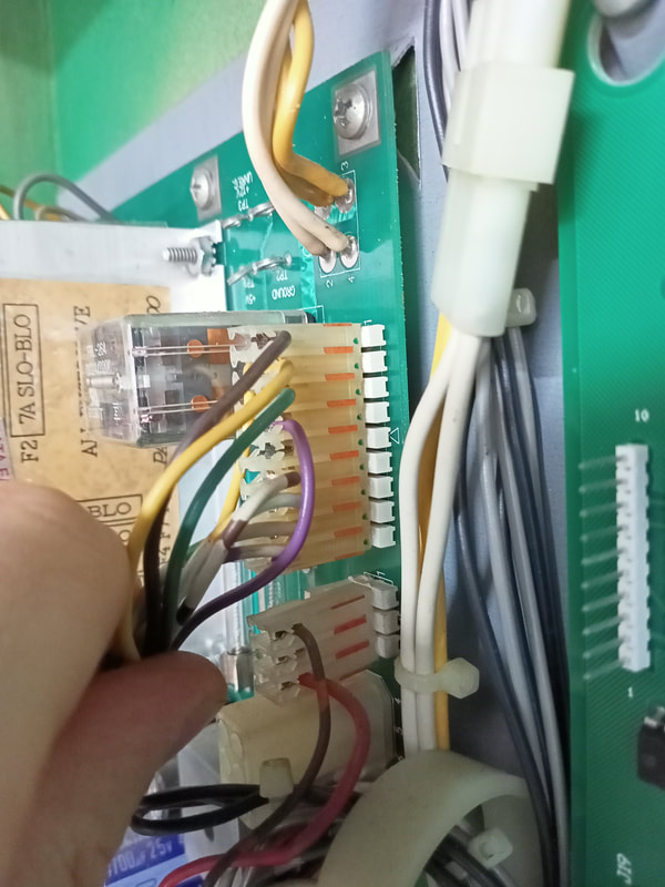
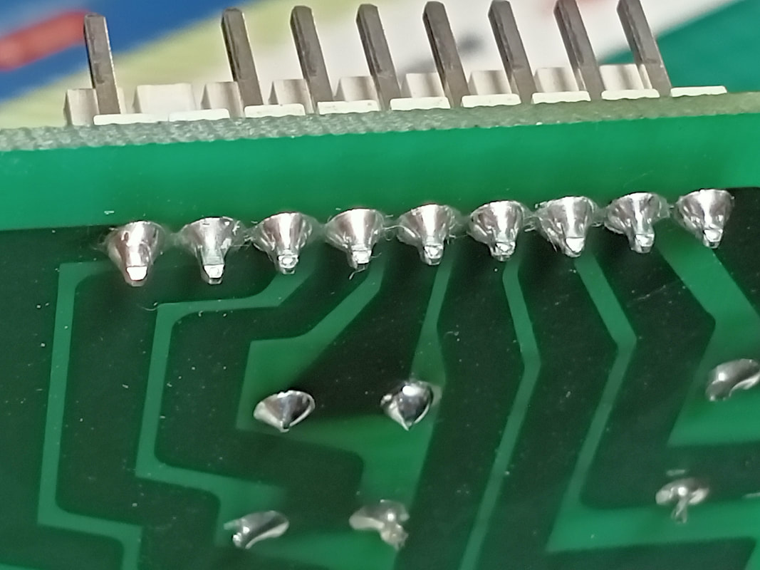
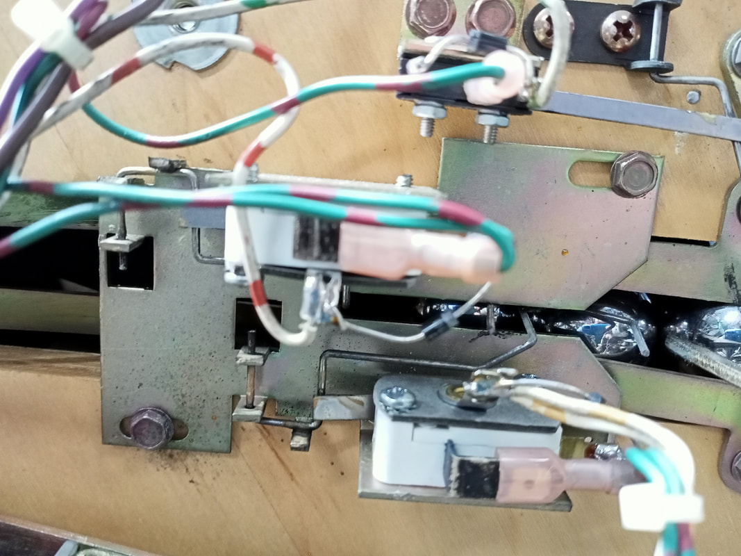
Unfortunately, the alkali leakage had progressed to one of the connectors at the bottom of the board (CN11). This connector is how the driving transistors for the coils connect to the playfield power board, so issues with this connector would cause funky coil behaviour. While there only appeared to be slight contamination of the terminals at the rear of the connector, this no doubt meant that the corrosion had spread to the conductors within the wires attached to the connector. To be safe, I opted to replace the wires as well. 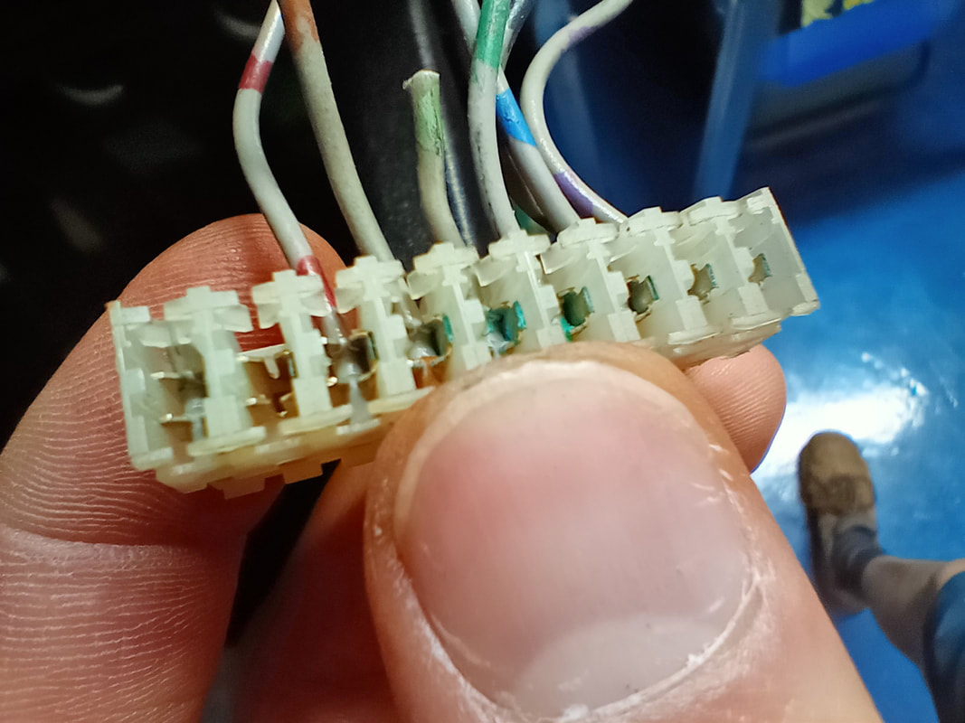
Rear side of the CN11 connector. Note the green corrosion on the three central terminals.
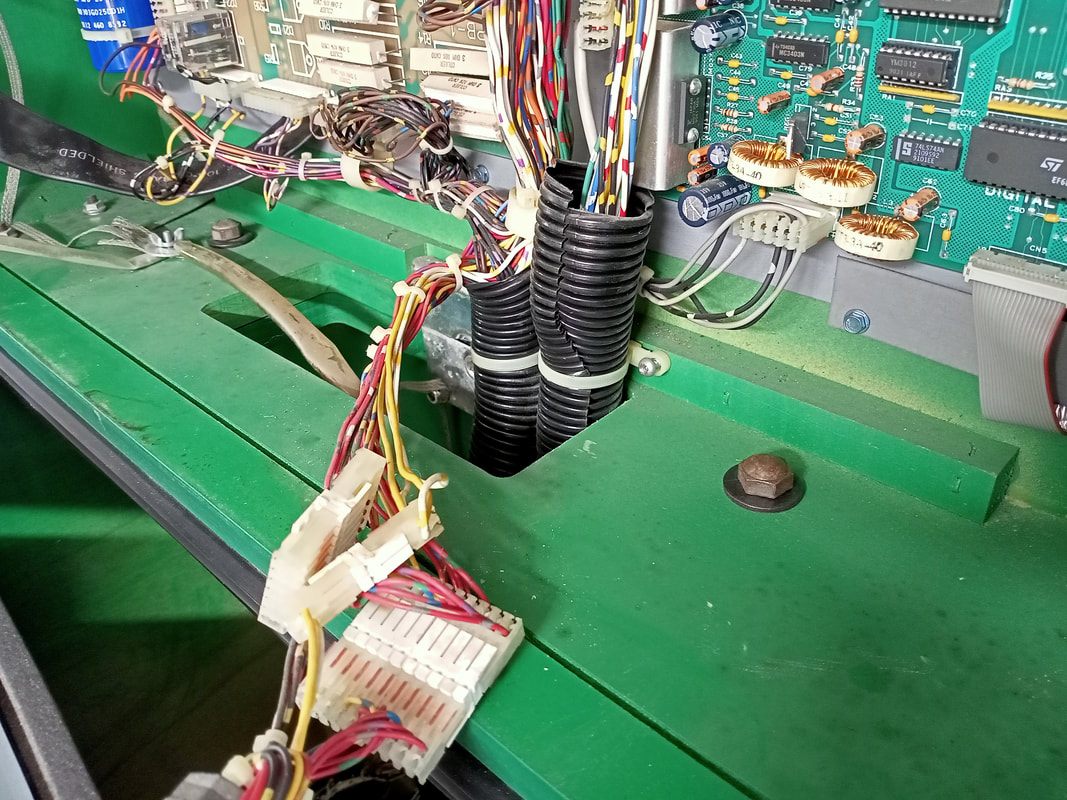
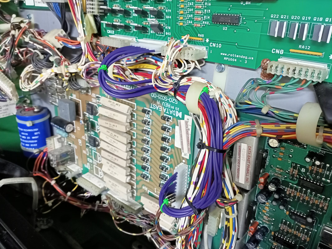
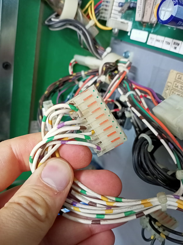
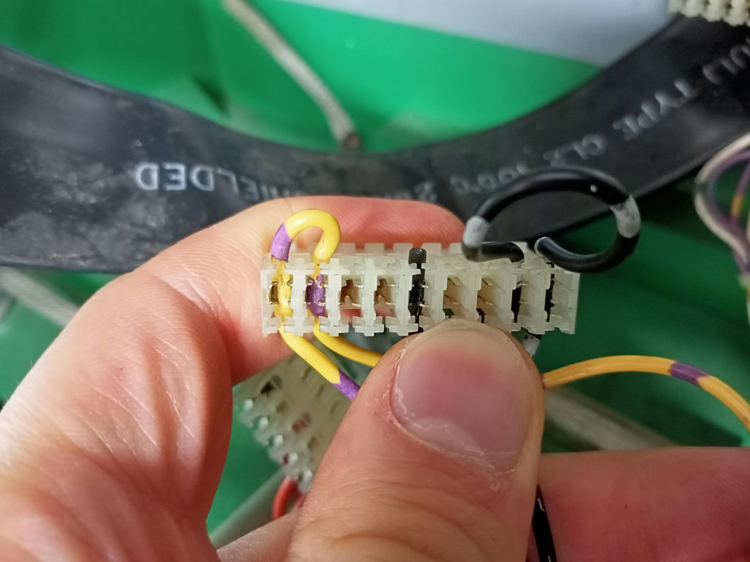
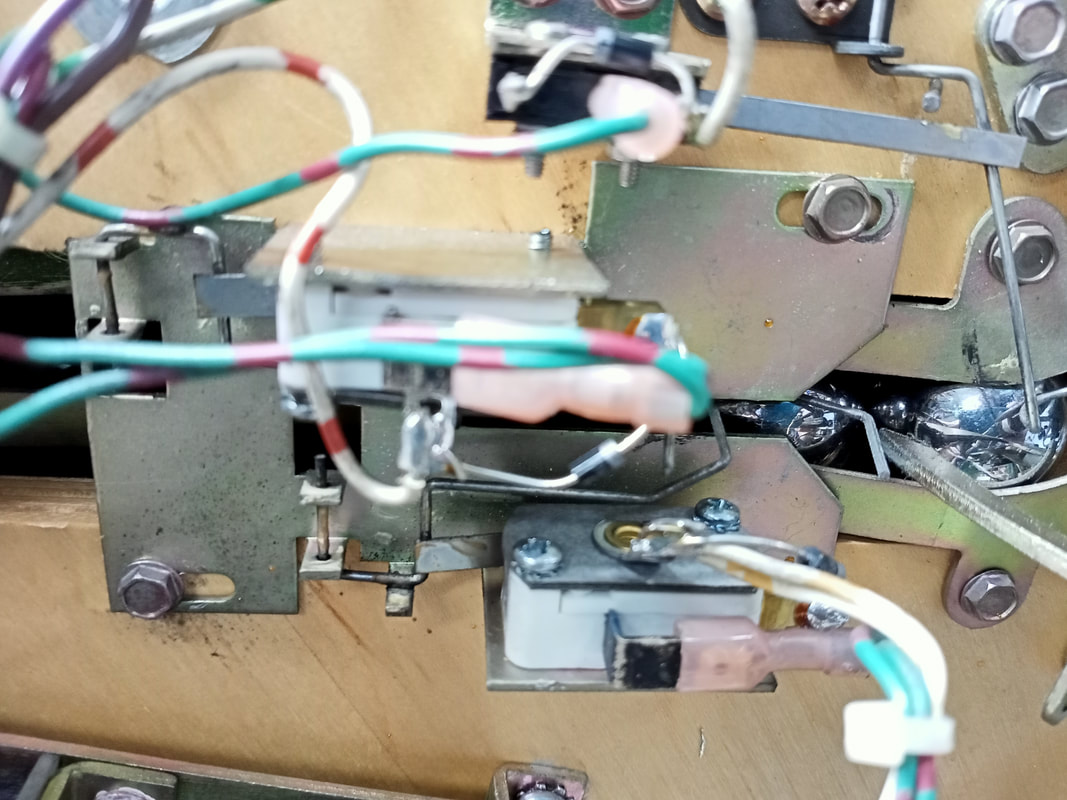
Instead of replacing a couple of the wires piecemeal, I found it easier to replace them all. When I stripped the wires back I noticed the corrosion went 20-30 cm down the conductors in a couple of the wires. With this kind of progression, it is safest to replace everything. The wires from this connector go to CN1 on the playfield power board (pins 1-8). for good measure, I replaced CN1 on the PPB, too. However, pins 9-13 on this connector are unrelated to CN11 on the MPU (they are actually from CN12). If you're replacing this connector, you'll have to move these across from the old collector to the new one. The CN11 connector on the MPU is a 9-pin 0.156" Molex style connector (element14, RTBB) and the CN1 connector on the PPB is a 15-pin 0.156" Molex style connector (element14, RTBB). The wires can be replaced with any wires of similar gauge and current rating. Use new Trifurcon crimp terminals for each wire termination, too (element14, RTBB, PSPA, Mr Pinball, Austral). Once this is done, you'll have a brand new harness to replace the old one. No more alkali corrosion to worry about! Simply terminate the extra brown wires on the original PPB CN1 connector to the new one to complete the harness. 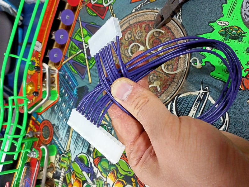
New wiring harness between MPU CN11 and PPB CN1.
After all of the above palaver, the board was plugged back into the game and turned on. Success! The game booted and was able to start a game as normal. Issues resolved!
Turboboost (ball launch) kicker issues
The turboboost (ball launch) kicker has a short but tumultuous history. It was used in a few of Data East's games including Checkpoint (Data East, 1991), Batman (Data East, 1991) and Teenage Mutant Ninja Turtles. The "Turboboost Kicker" name refers to the name the assembly was given in Checkpoint, and the name seems to have stuck (or someone forgot to change it in the manual for subsequent games). However, the kicker was poorly designed. The kicker arm was made to sit in front of the shooter rod, which would collide with the rear of the kicker arm, transferring energy to the ball and sending it up the shooter lane. In theory, this makes sense, but in practice the mechanism just isn't very reliable. It breaks often, and people's attempts at repair always make it worse. When the kicker arm tried to launch the ball, it would move only a fraction of a centimetre and couldn't move the ball. It had no chance of launching it up the ramp.
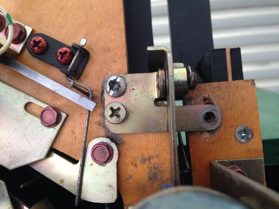
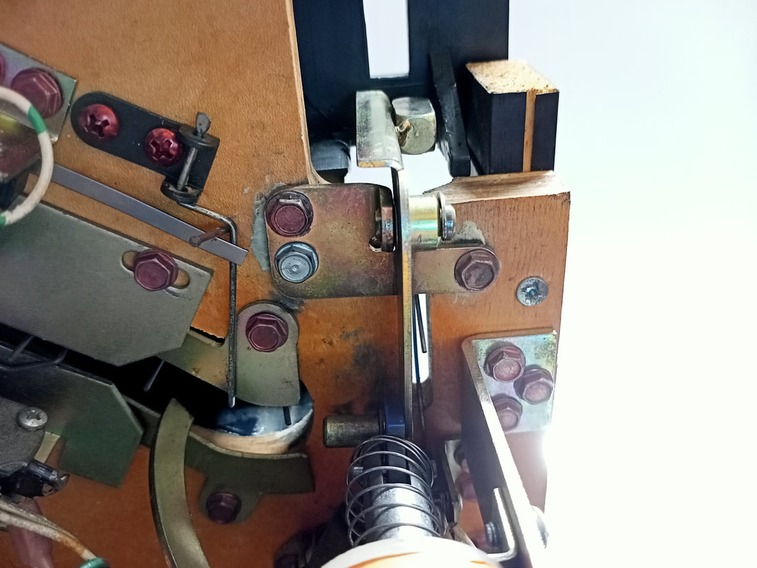
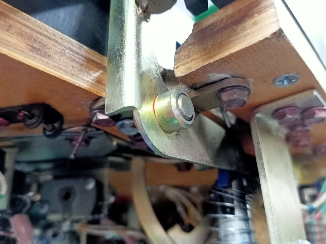
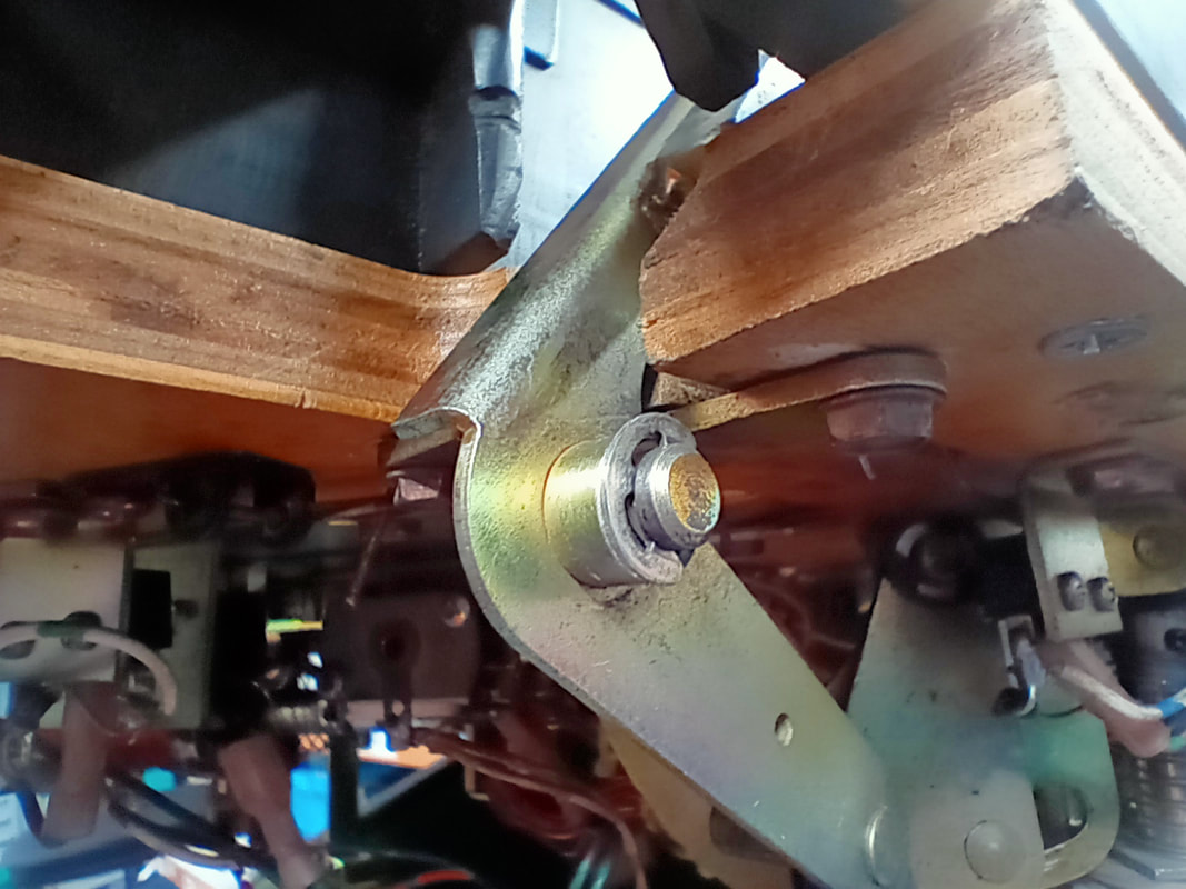
Action Pinball has a great article with information and parts advice for replacing this troublesome assembly in a variety of Data East games. However, Teenage Mutant Ninja Turtles is an exception to the rule, and it is recommended to leave the assembly as originally intended as upgraded Stern parts do not fit on the Ninja Turtles playfield. So what was causing the kicker not to work? It turns out, a lot of things. The assembly was attached to the underside of the playfield with an assortment of incorrect screws. I got rid of these screws and I filled the holes in the underside of the playfield with Selley's Knead It, and left it to harden. Once solid, the kicker arm and baseplate were realigned on the playfield so that the kicker arm was in the centre of the shooter lane. Then the assembly was reattached to the playfield with the correct screws. First problem solved.
Next problem. The assembly was missing the E-clip (part no. 270-5004-00) which attaches the kicker arm to the pivot. This meant that the arm had a lot of movement and slop, which would rob the kicker of a lot of power. Luckily, I found the E-clip in the cabinet near the power module. It was still intact, so it just needed to be reattached. Second problem solved.
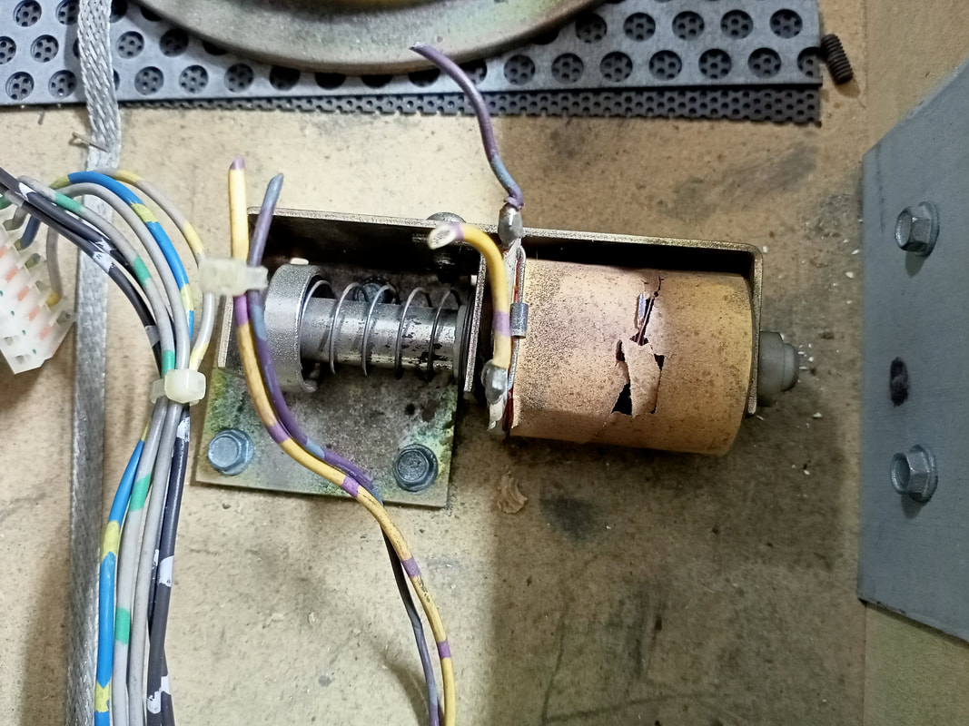
Another problem, and a major one. The coil for the ball launch kicker had overheated. The plunger wasn't able to move anymore as the coil had cooked to the point that it had melted a little, constricting the plunger so it could not move. The coil wrapper was slightly charred, too. Of course, the first step was to replace the coil. However, further investigation was warranted to determine why the coil burned up in the first place. 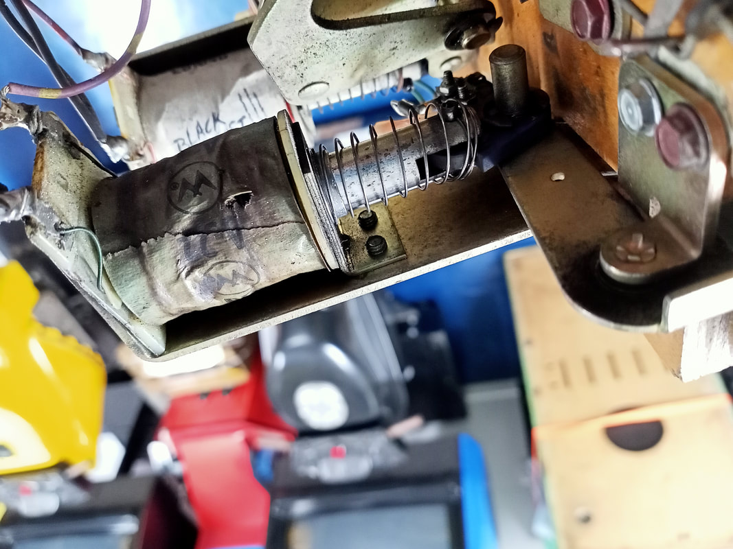
Burned up ball launch kicker coil.
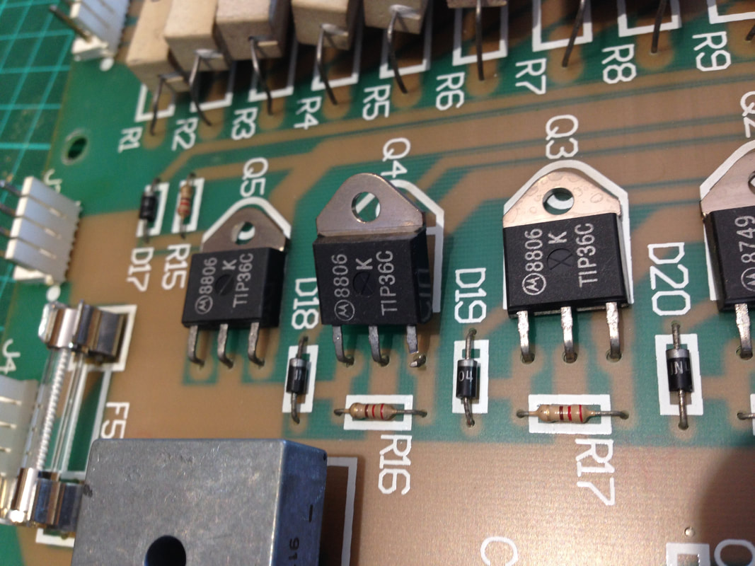
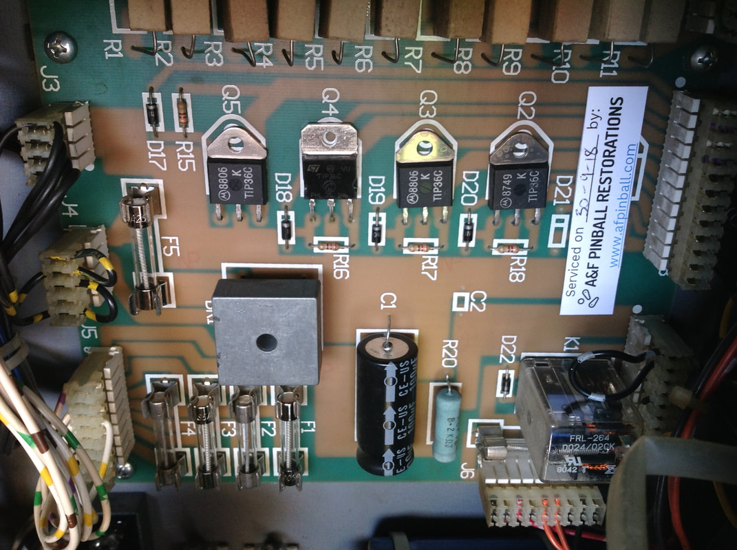
The subject coil was actually a Williams A-22-550 coil (2.3 ohms resistance). Having a Williams coil is not necessarily a problem, as long as it is comparable to the original coil. The original coil for the ball launch kicker is meant to be a 22-600 coil (part no. 090-5023-00, 2.2 ohms resistance). This is a very similar resistance, wire gauge and number of windings to the original coil, so I consider the Williams coil was compatible for this application. For an informative discussion on substituting coils, check out this Pinside thread. Time to investigate further. The ball launch coil is driven by transistor Q5 on the playfield power board, which in turn is driven by Q43 on the MPU. Transistors can be tested with diode test on a multimeter, and should always be checked whenever a coil has failed. Transistor Q43 on the MPU tested fine, reading between 400-600 mV in diode test. However Q5 on the playfield power board did not pass diode test. It failed miserably. There was an internal short somewhere in the transistor, with shorts present between emitter, collector, and base. Not good! It appears that while the transistor was locked on, the coil burned up, causing the present issue. With the fault in Q5 discovered, it was time to change the transistor. These transistors are TIP36C PNP types (Jaycar, Austral, Mr Pinball, RTBB, PSPA). The associated diode and resistor both tested fine (however good practice is to replace both of these components, too). While testing the other transistors on the playfield power board, Q4 was also found to be faulty. See the section on "Knocker not working" for details on that one. Both TIP36c's were replaced. After that, I went into coil test and checked the Turboboost kicker. It worked well, however, it would only get the ball onto the playfield if I held the shooter rod back. This was an issue with the shooter rod assembly - see the next section for details on that. The coil itself worked without issue, which was the main objective of this repair.
The kicker arm (part no. 515-5350-00) on the Turboboost assembly itself seems to take a real beating. There were a bunch of metal shavings inside the cabinet from the front face of the arm, which had been bashed too many times by the ball. This is only really a problem because it may cause metal shavings to end up on the playfield as well, which will damage it. However if you keep the game clean and clear out any debris regularly, this shouldn't cause any issues. New arms are readily available (RTBB, PSPA).
Shooter rod issues
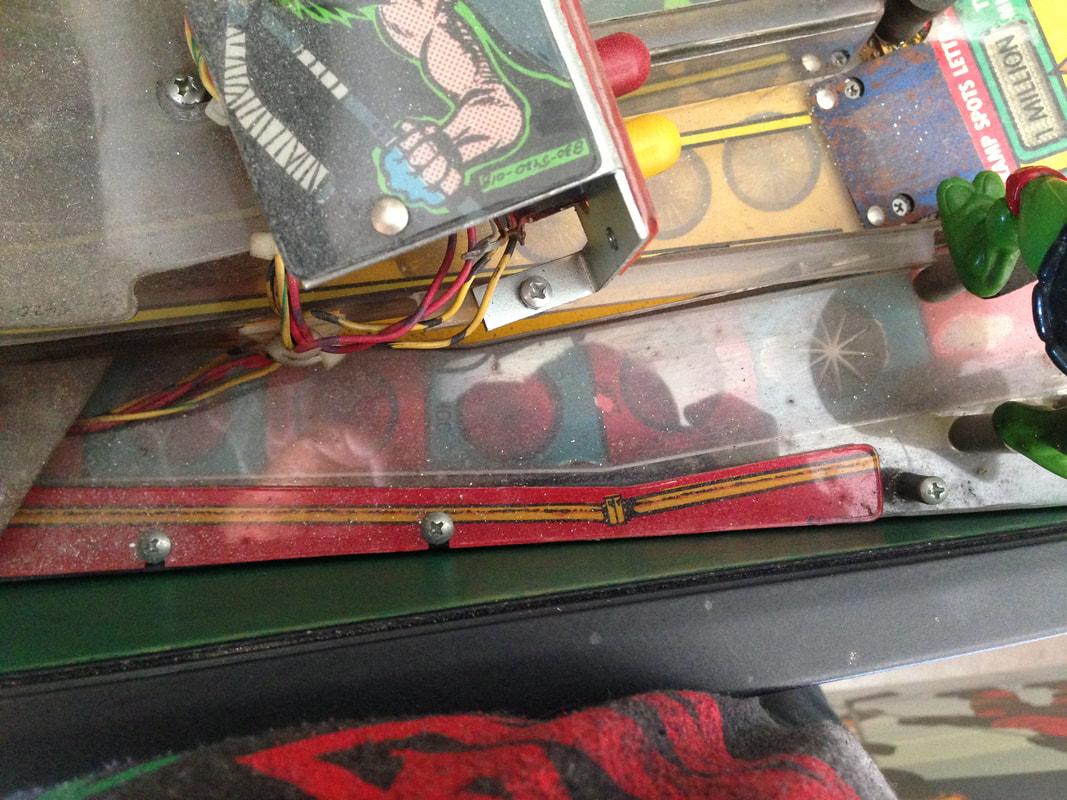
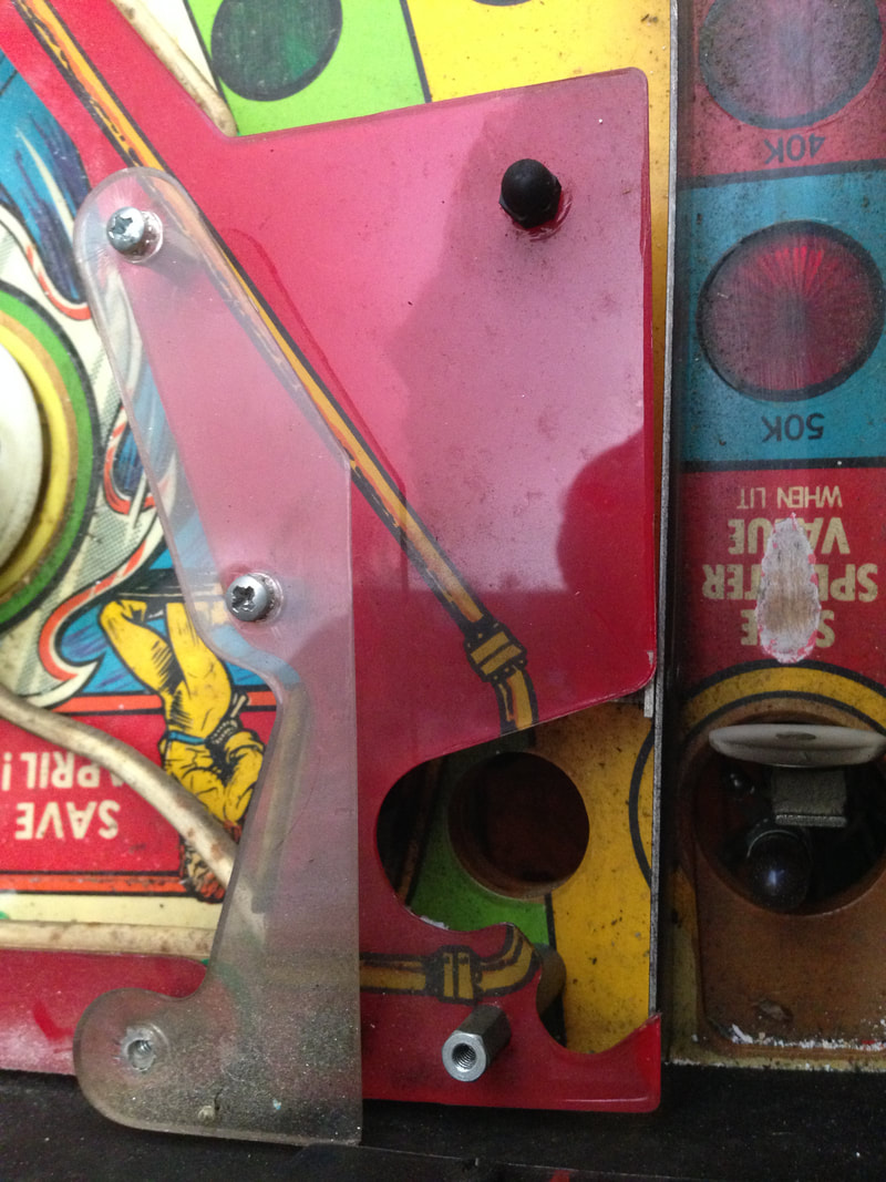
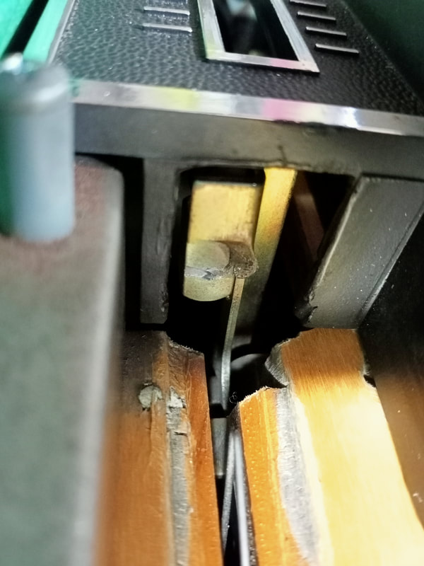
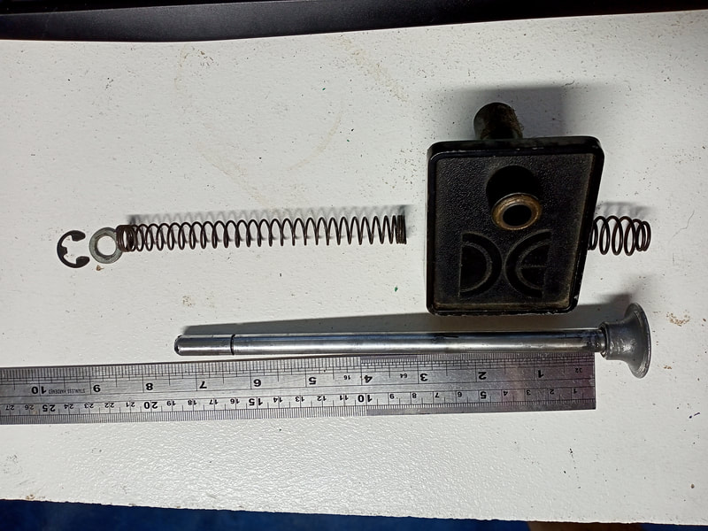
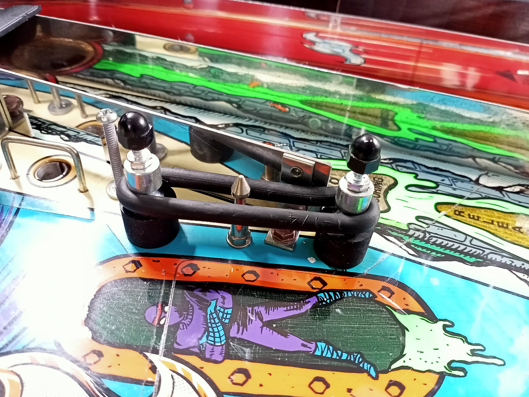
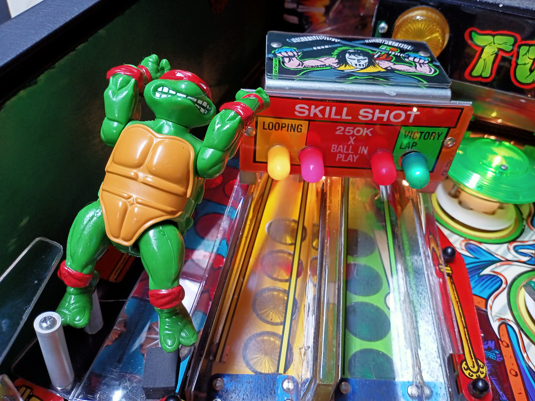
Now that the electronic issues with the Turboboost kicker were fixed, it was time to make sure the shooter rod worked smoothly physically. Check for smooth and reliable action of both the kicker arm and the shooter rod. Make sure a ball can be launched onto the playfield easily by both methods. If the ball launch coil is unable to send a ball up the ramp, check the coil assembly for missing parts or slop. If the shooter rod cannot get the ball onto the playfield, check that it is an appropriate length and that a sufficiently strong spring is installed. High-tension red springs (Stern part no. 266-5001-02, RTBB, PSPA, Austral, Mr Pinball) are suggested for this application. I wasn't able to reliably get the ball up the ramp with every pull of the shooter rod, even if I puled it back all of the way. Something wsa wrong. One thing to be aware of is that the shooter rod on Turtles did not come with a rubber tip installed from the factory. Apparently this is by design. By design or not, this is a horrible idea in my opinion, as metal-on-metal contact is going to damage both parts. I like to keep a rubber tip on the shooter rod regardless. However, be careful that the shooter tip does not push the kicker arm from the ball launch kicker too far forward. If it is pushed forward, the kicker will not move through its full range of motion when striking the ball, causing it to have much less power. This was a problem on this game, and was one reason why multiple balls would get stuck in the shooter lane during multiball. Note that a shooter tip will generally increase the length of the shooter rod slightly, so a slightly shorter shooter rod may be necessary so that it does not push on the kicker arm again. 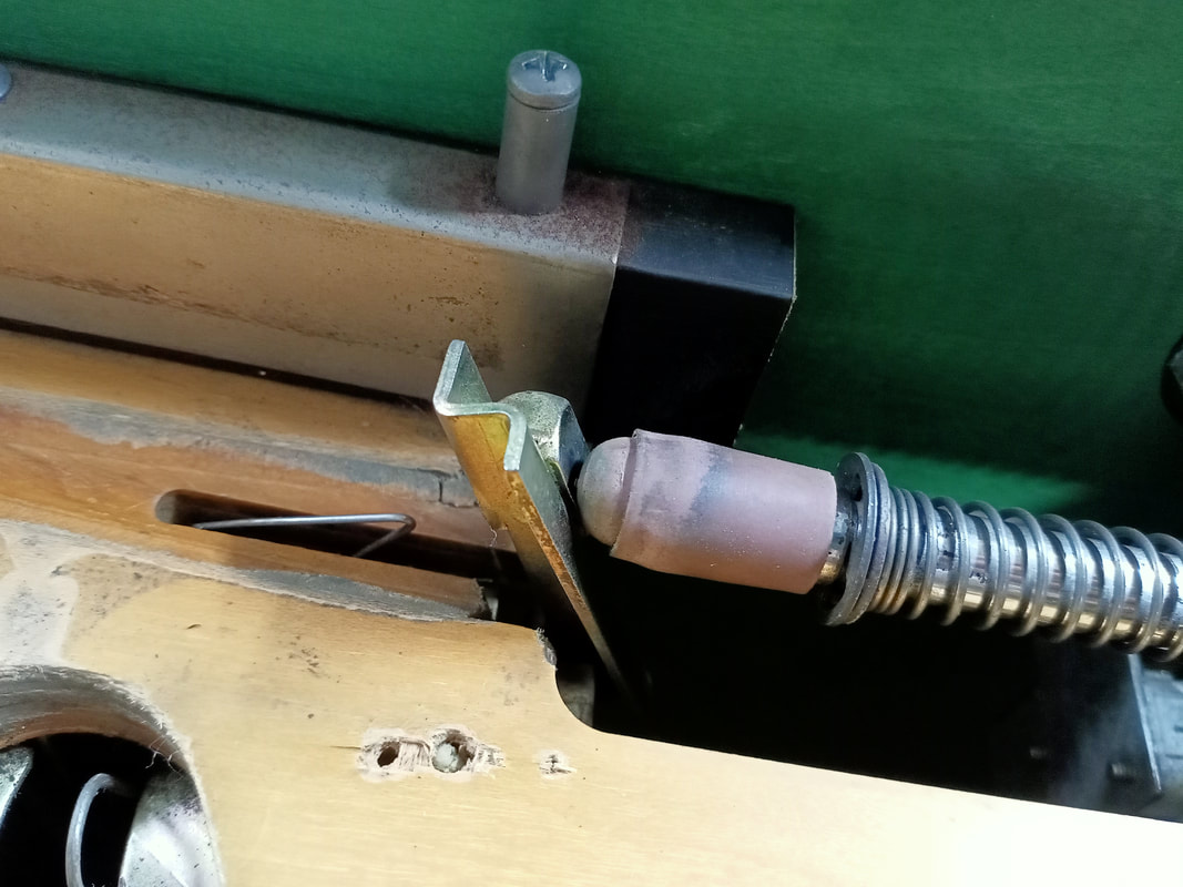
This shooter rod and rubber tip are too long, and are pushing the kicker arm out of place.
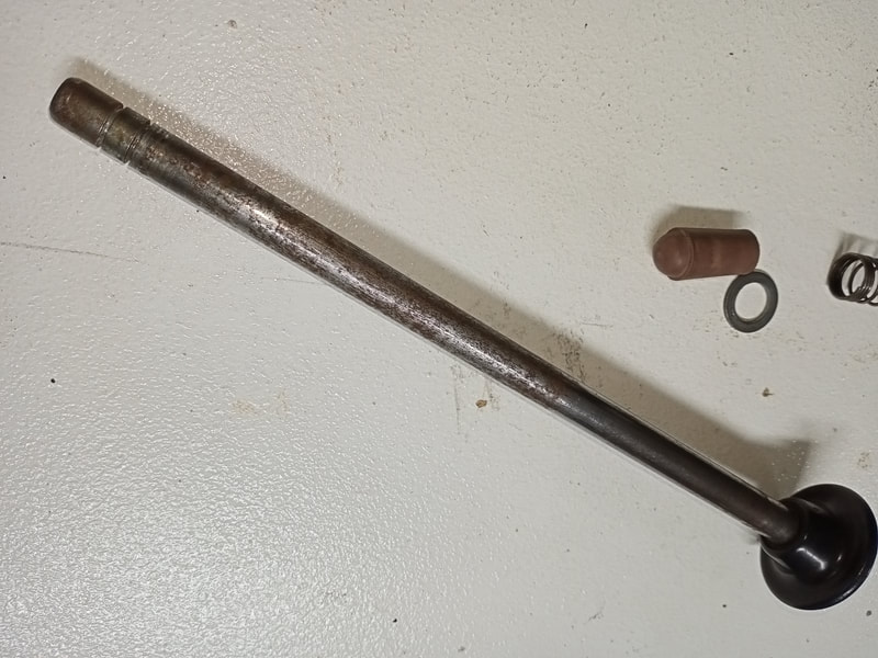
Out of interest I removed the shooter rod out of my own Turtles game to see what an "original" rod should look like. The shooter rod in my other Turtles machine was 7-1/4" long, while the rod in this game was 8". Huge difference! No wonder this rod was pushing on the kicker arm; it was just too long. I replaced the rod with a shorter one (7-1/4") but still found that it could only launch the ball onto the ramp if it was pulled back all the way. And on some occasions, it would fall just short. Making it just a little bit longer would remedy this, and I did that by installing a rubber shooter tip again. This made the rod the perfect length.
Even after replacing the shooter rod with the another of the correct length, and making sure the tip did not push the kicker arm forward when at rest, the shooter rod was still a little "rough". I had a closer look at it and realised that there was some surface rust and dirt on it. A quick session on the buffing wheel got it nice and shiny again.
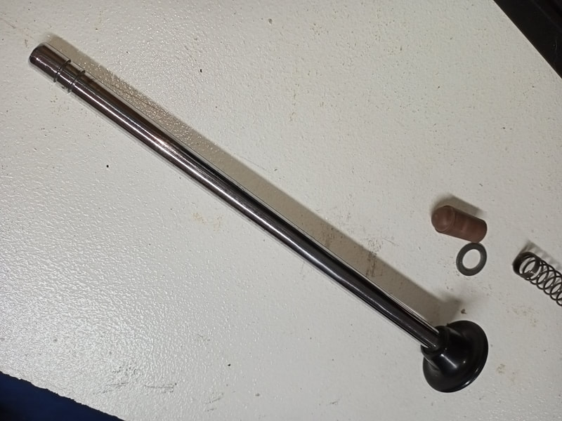
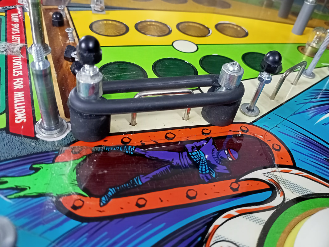
I also cleaned out the shooter housing so there was no crud in there to slow down the rod. Once this was done, the rod moved fluidly with no resistance, just the way it should. This gave the shooter rod even more power when launching the ball, which was good. 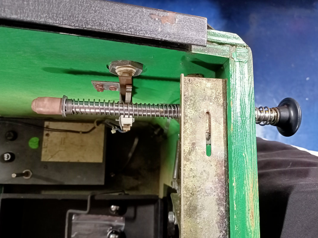
Fully serviced and working shooter rod assembly.
Most flashers broken
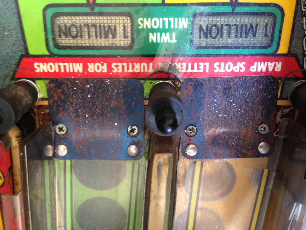
Data East games use a lot of flashers. I don't quite know why, but they do. When I first tested all of the flashers I thought I may have had an issue on the board or with the wiring, as only a couple of them in the whole game actually worked. I've seen plenty of abused games with lots of lamps out, but there are usually a fair few flashers still working. As it turns out, there was no weird issue, most of the flashers were just broken and in need of replacement. Flashers are connected in parallel in Data East games, usually with four flashers in each "string". When one flasher is not working, the other three get supplied with extra current, which tends to stress the lamp filaments and causes them to burn out more quickly. With more than one flasher not working, the problem is exacerbated. This was probably the reason so many of the flash lamps were out. Pinwiki has a good explanation of the issue.
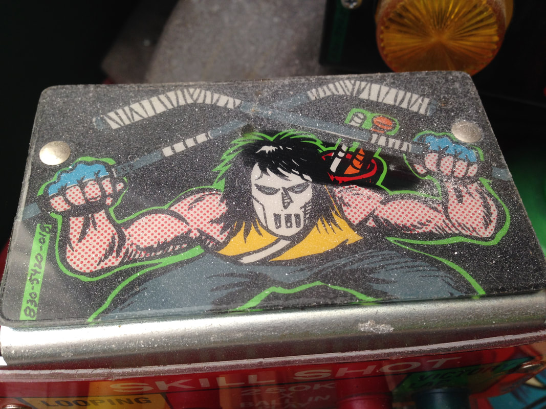
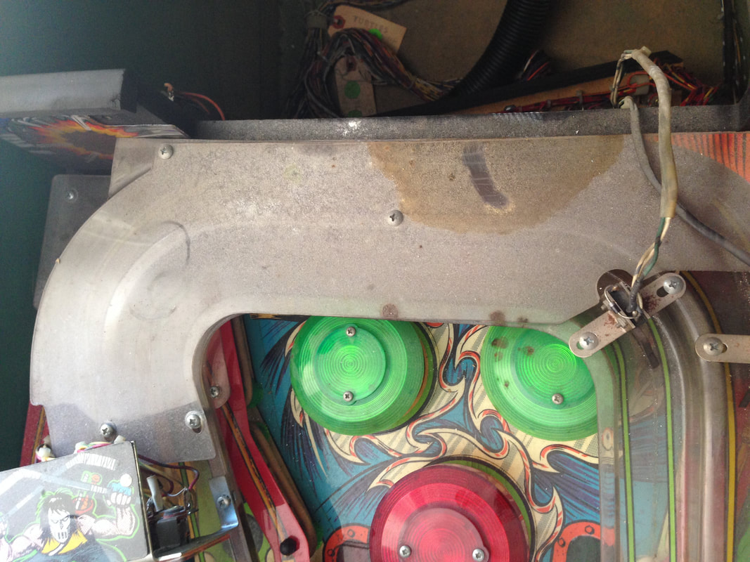
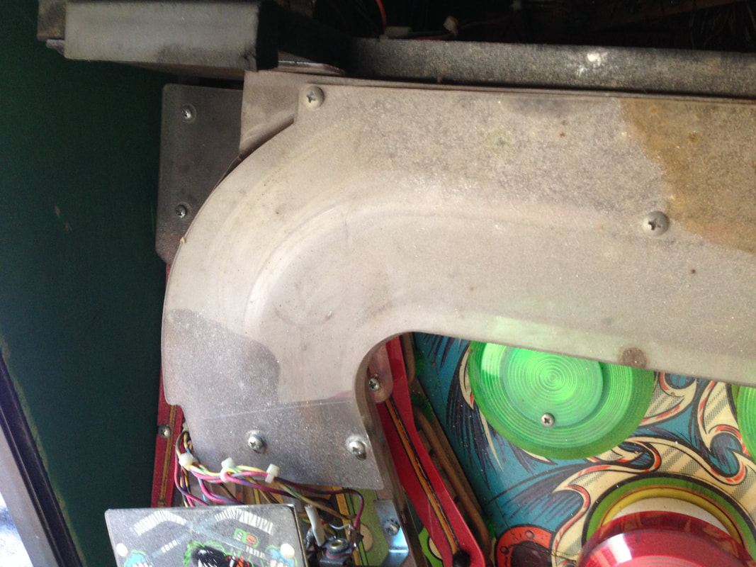
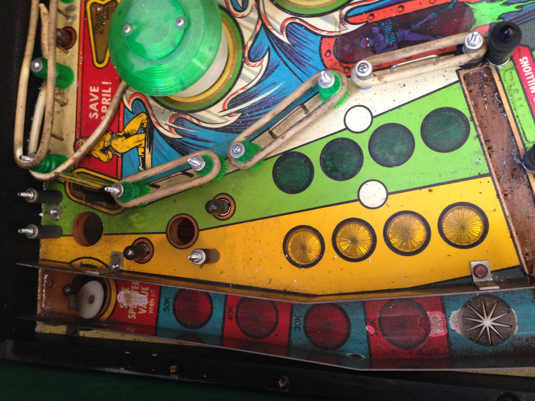
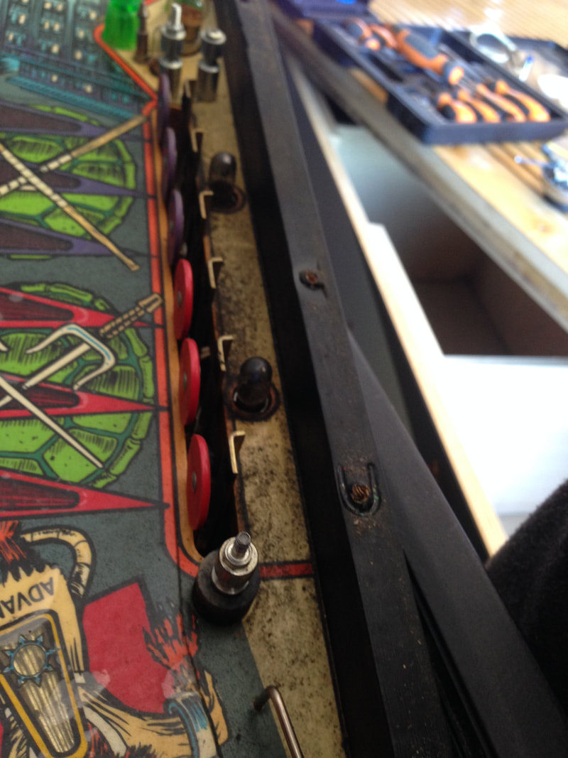
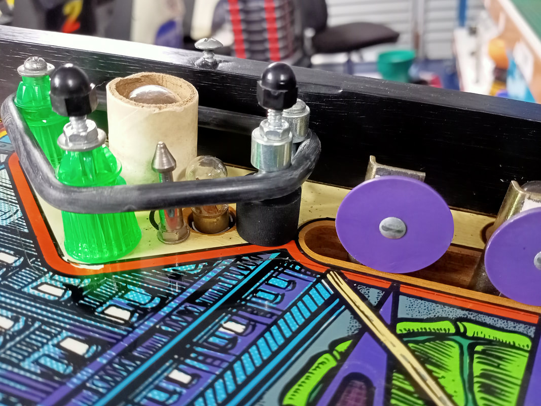
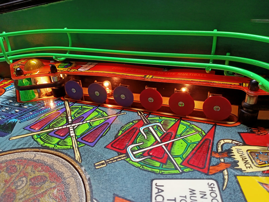
I used about thirty flashers in total on this game (a mix of 906s and 89s). In particular, the lamp board with eight flashers on it below the ramps had no working flashers at all. Then, there were four flashers behind a large red insert on the back panel attached to the playfield. None of those worked either. So, whenever you work on a Data East game, make sure you have plenty of flashers to spare! 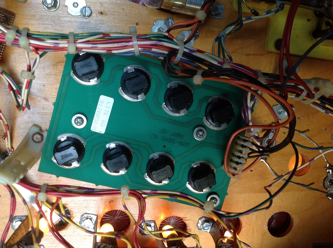
Check the flashers on the lamp board under the ramps - most of them will probably be dead!
No power to flippers
The flippers were not working at all, so I made sure there were no loose wires anywhere. These all seemed OK. Switches were not the issue, either. However, I was seeing no voltage at the flipper coils when I should have been seeing ~50VDC. Hmm.
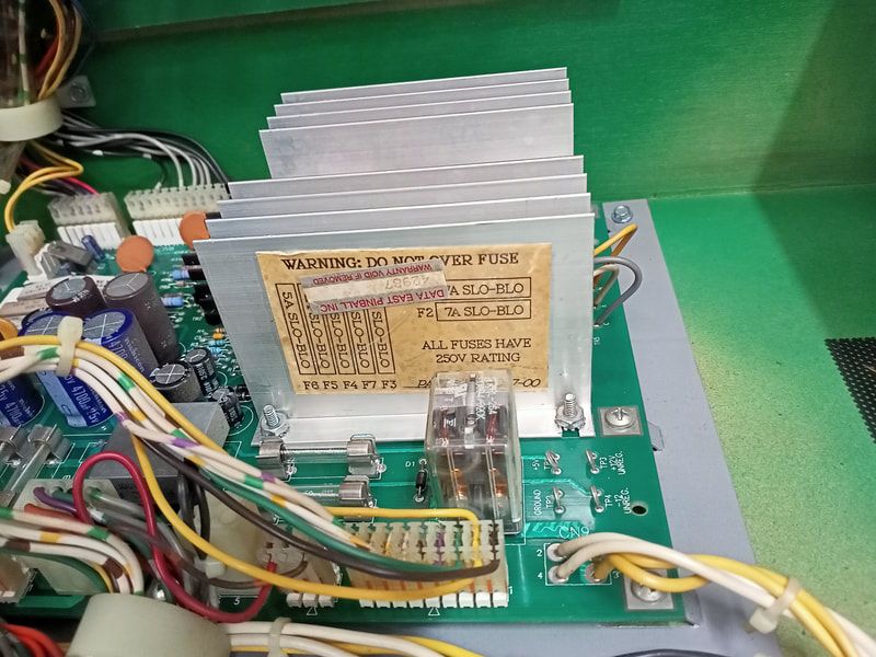
If wiring checks out OK, then voltage drop issues are more likely to be associated with the playfield power board. This is where the problem was. One of the fuse clips for fuse F5 (50V coil fuse, positioned on input side of BR1) had cracked and was no longer making good contact with the fuse. Therefore, no power was getting to the flippers. The fuse clips used on Data East games are of poor quality and crack easily. So if you begin to get intermittent coil or flasher problems, suspect the fuse clips first. I was able to grab a small pack of new clips (Jaycar) to install into the board. Once the new clips were in, power returned. 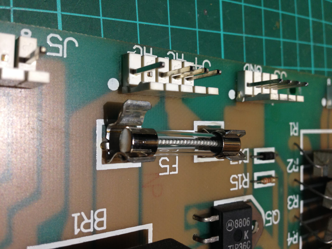
Broken fuse clip at F5 on the playfield power board.
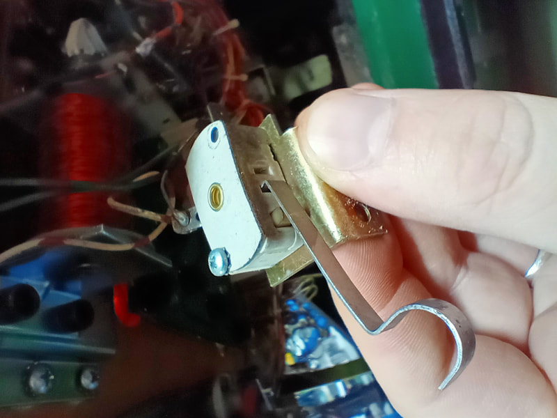
The next issue was that the right flipper switch was not being recognised in switch test. However, the flipper worked normally during a game. What gives? Data East was the first company to introduce solid state flippers. The way they implemented the flipper circuitry is a little different to Gottlieb or Williams. The flippers are controlled by a solid state flipper control board (part no. 520-5033-00) mounted on the left side of the cabinet. The flippers are, in a way, separate to the rest of the MPU-controlled switches in the game. A press of the flipper button will trigger the relevant flipper regardless of whether that switch is connected properly to the MPU. That's because the flipper board provides the flipper coil's path to ground before the signal is sent to the MPU for processing. The right flipper activated properly when the flipper button was pressed, according to the theory of operation described above. However, the right flipper switch was never actually being recognised by the MPU as a switch closure. As long as the flipper works, this shouldn't really matter, right? Wrong! This has the annoying effect of making it impossible to scroll right when selecting high score initials, and also making it impossible to scroll rightwards through the test menus. Initially I suspected there may have been a fault with the Rottendog MPU board I had just installed. However, I manually jumped the switch column and row associated with the right flipper (column 2, row 8) and could see the MPU register the flipper switch. This eliminated the MPU being faulty. I then tested the wiring for the right flipper switch and made sure there was good continuity from the switch, to the flipper board, to the MPU. There was a good connection. Next, I reflowed solder on the flipper board header pins and checked all of the fuses and fuse holders. These were all good. At this point I was stumped. So, I checked all of the components on the flipper board. One of them gave odd values when testing - the transistor at Q5. I had a sneaking suspicion this transistor may have been involved in the right flipper switch circuit. According to the manual, it did! It was connected to switch drive 2, and switch return 8. Switch return 8 was where the right flipper button switch sat. I installed a replacement PN100 transistor, a generic replacement for 2N3904, (Jaycar). Once installed, the right flipper started registering properly. Nice! 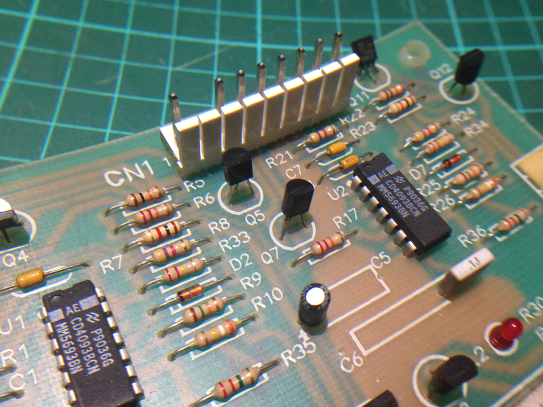
Q5 after replacement with a PN100 transistor.
Even though I now had power at the flippers, they were so weak that it was almost as if the flipper coils were not being supplied their full voltage. After the fuse clip replacement, they were definitely getting their correct voltage, but the worn flipper parts robbed the flippers of any power. I grabbed a flipper rebuild kit (RTBB) and installed it and the difference was night and day. The flippers suddenly had the power to make the ramp and orbit shots at the top of the playfield. 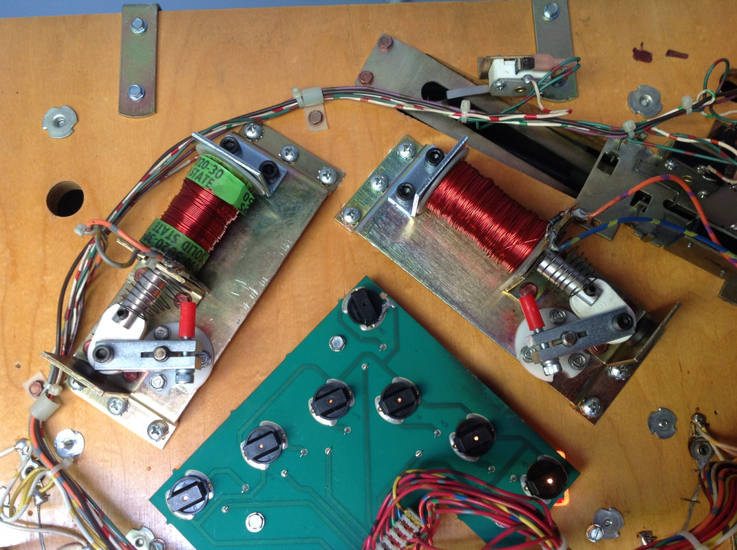
Freshly rebuilt flippers; nice and strong!
Knocker coil stuck on
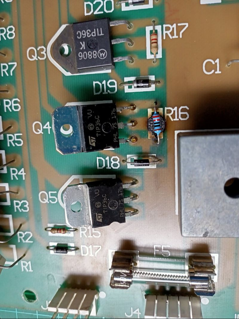
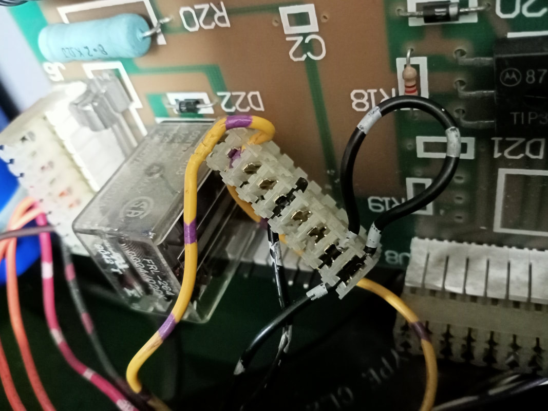
After installing the new MPU board, I was keen to get the game playing again. Unfortunately I didn't get too far, because every time I turned the game on, the knocker coil would lock on. I checked the schematics and the knocker is controlled by a drive transistor on the MPU as well as a TIP36 transistor at Q4 on the playfield power board. I tested the transistor on the playfield power board and found that it had developed a short internally. I checked the diode and resistor associated with the transistor and they were both fine. Replacing the TIP36C was all that was needed to restore the knocker to normal.
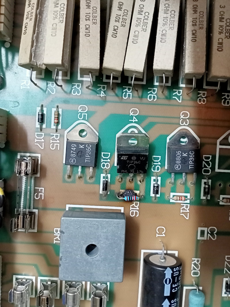
But, that wasn't the end of the drama with Q4. Some time after I had fixed the transistor, the knocker locked on again. This time, the failure was more spectacular. Resistor R16, which is in series with transistor Q4 for the knocker coil, decided to go nuclear and catch fire. The aftermath looked pretty nasty, but it actually cleaned up really well. Once there is a failure this spectacular in the circuit, it is generally a good idea to replace all affected and nearby components as some of them may have been damaged by the event. Now it was time to install a new transistor at Q4, new resistor at R16, new diode at D18, and for good measure, a new knocker coil.
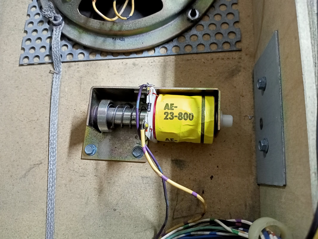
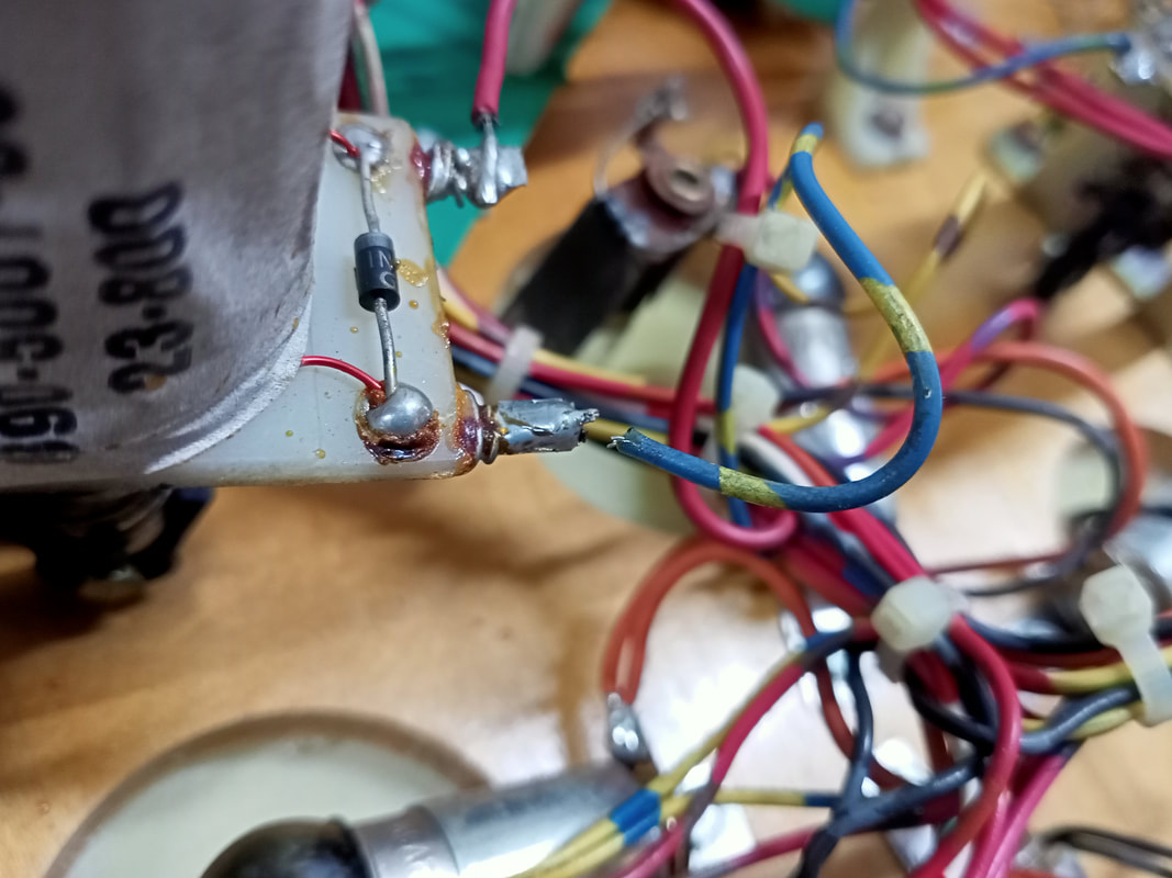
With the circuit entirely refurbished, the knocker started to work like a charm. I didn't have a Data East coil in stock to replace the knocker (part no. 090-5001-01). However, it was an AE-23-800 coil, and Williams 23-800 coils are an acceptable substitute for this one. So, I installed the Williams coil, and the coil operated normally. All done.
String of general illumination lamps not working
This was an easy one. The general illumination lamps on the left side of the playfield would not light up even after I replaced all of the lamps. So, the lamps were not the problem. Time to check the backbox. Normally, the general illumination connector on the power supply board (CN8) or on the playfield power board (CN5) is tarnished or otherwise damaged, causing lamps not to light. This problem in particular is discussed on Pinwiki. Surprisingly, these connectors were both perfectly fine.
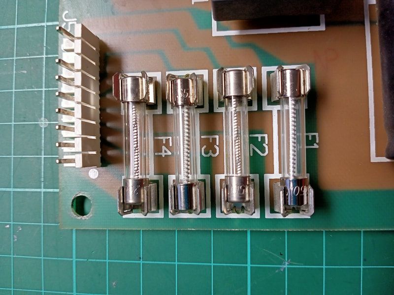
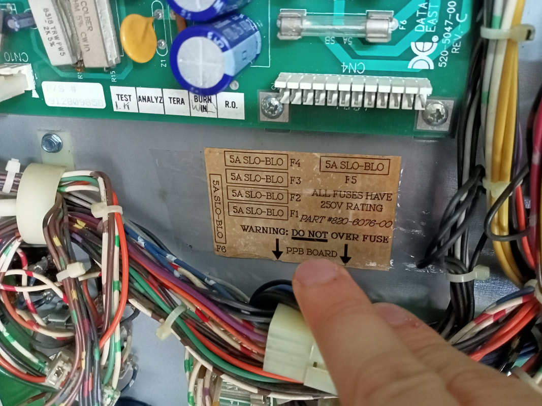
While inspecting the playfield power board and the general illumination fuses at F1, F2, F3 and F4, I found the issue. One of these fuses had blown, so I tried to replace it. However, in the process of replacing the fuse, I realised that one of the fuse clips had cracked, and was no longer holding the fuse (F4). When I checked the rest of the fuses on the board, I found another fuse clip which was almost broken as well (F2). I replaced all of the affected fuse clips (Jaycar) and broken fuses (Jaycar).
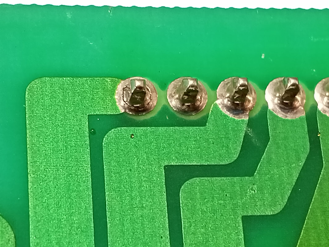
When I reinstalled the board, I still had the same problem; none of the lamps on the left side of the playfield would work. What the hell! Time to take the playfield power board out again to recheck my work. The fuses and clips were all fine, but I discovered another problem when checking the rear side of the board. There were cracked solder joints at the rear of connector CN5, which is the general illumination connector. I reflowed all of the pins and the lamps worked without issue after that. Just goes to show the importance of checking everything on the board before putting it back in the game!
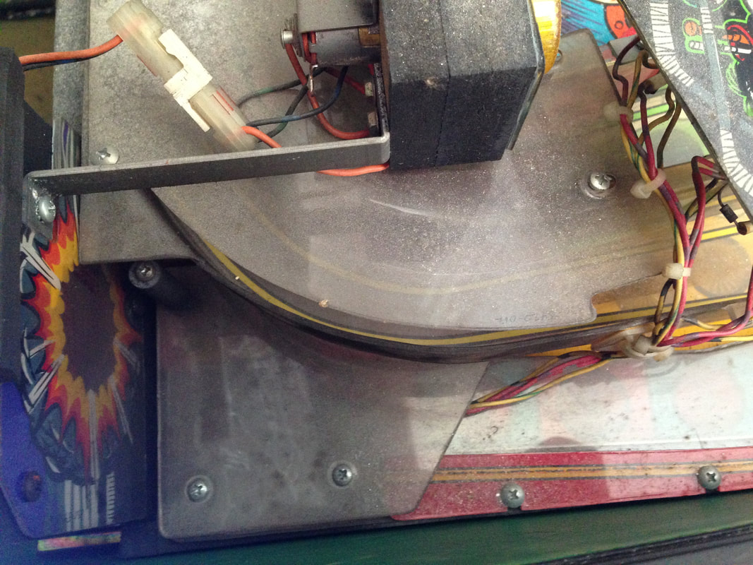
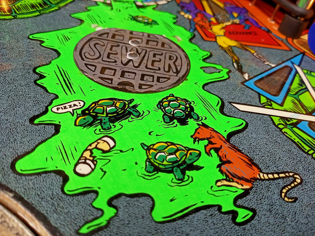
Sewer kickout issues
When balls are sent to the sewer via the hole at the rear of the playfield, they roll down a subway ramp and into a super vertical upkicker (VUK) assembly (part no. 500-5320-00). Then they get shot up through the sewer manhole cover and return to the playfield. When servicing the game, remember to remove the subway assembly and give it a good clean, as a lot of playfield crap tends to end up in here. Removal is easy. You need to cut two zip ties which secure the VUK switch and coil wires. Then, undo the two wood screws at the end of the subway near the top of the playfield. Two metal screws secure the subway to the super VUK assembly. The subway pops right off after those screws are all undone.
About 10% of the time, balls sent into the sewer were not getting kicked out. This would eventually trigger a ball search, and more often than not, the game would serve another ball into the shooter lane as well as ejecting the one in the sewer. This would confuse the game no end. The Data East ball search algorithm is really no good; it gives up and serves up another ball way too quickly. Fixing this just required a simple adjustment of the switch on the super VUK assembly. The switch mounting screws cannot be moved around, so you need to bend the switch blade itself. I adjusted this for better contact with the underside of the VUK plunger cap and it started to register the ball 100% of the time. 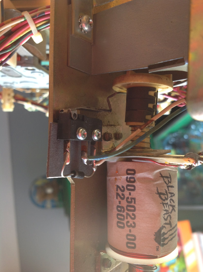
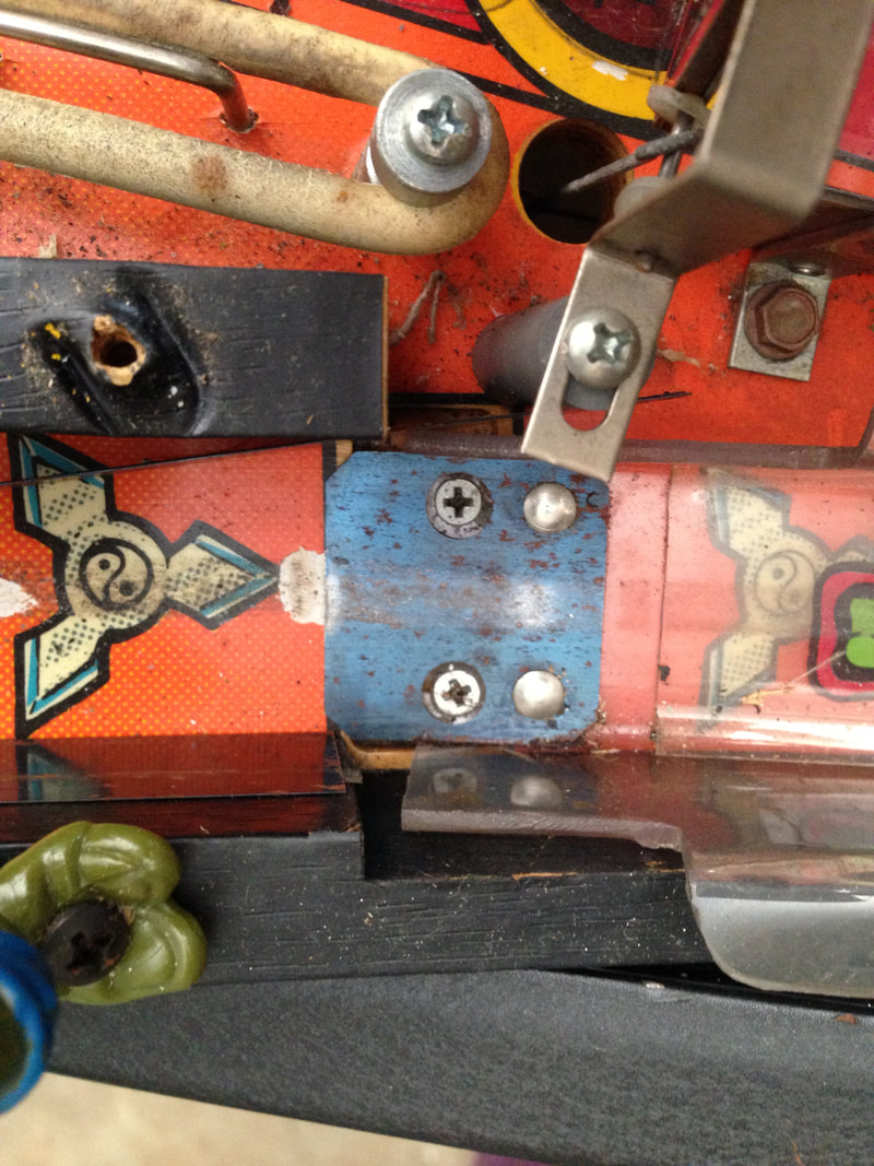
Switch on the vertical upkicker assembly.
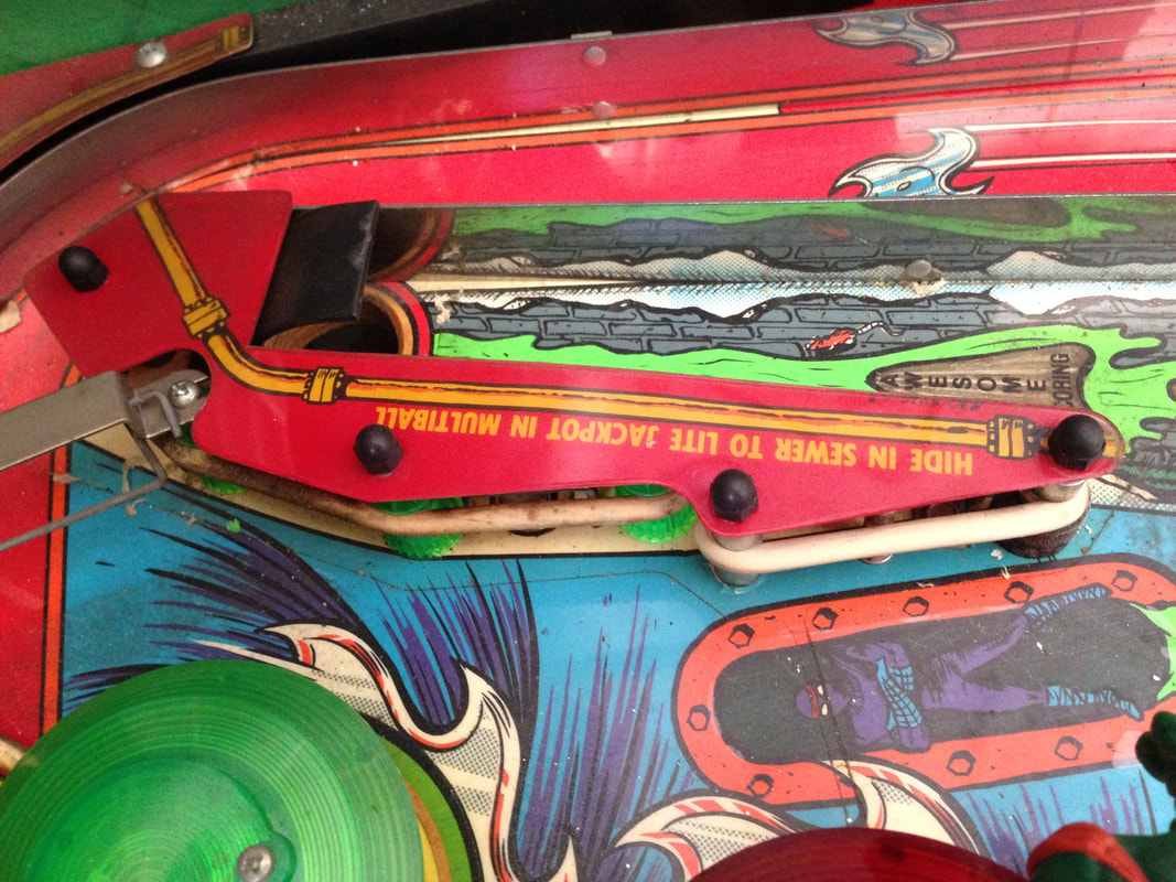
Another issue with the sewer kickout was that sometimes balls would be ejected and get sent straight down the middle. As there is no ball save programmed into the game to compensate for this, this results in some very frustrating ends to games. The super VUK assembly actually has ball "deflectors" on either side of the assembly, above the upkicker cup. These serve to guide the ball as it exits the assembly. If a deflector is pushed inwards towards the centre of the assembly, it will push the ball further in this direction as it exits, and vice versa. I just needed to adjust these deflectors until the kickout stopped sending the ball down the centre drain, and instead pushed it towards the left flipper. Simply bend them as necessary with pliers. 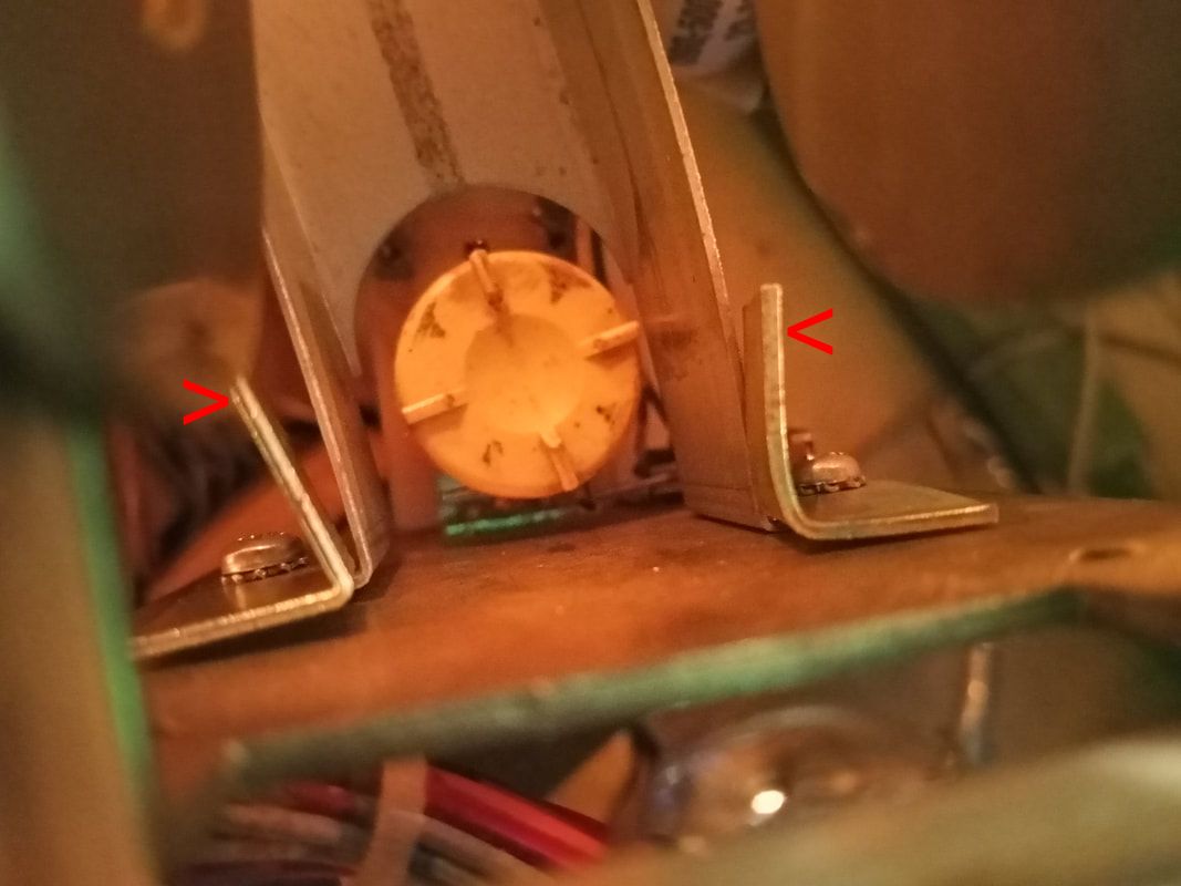
Ball deflectors (indicated by red arrows) on the VUK assembly.
Trough eject mechanism not feeding balls into shooter lane
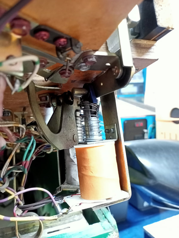
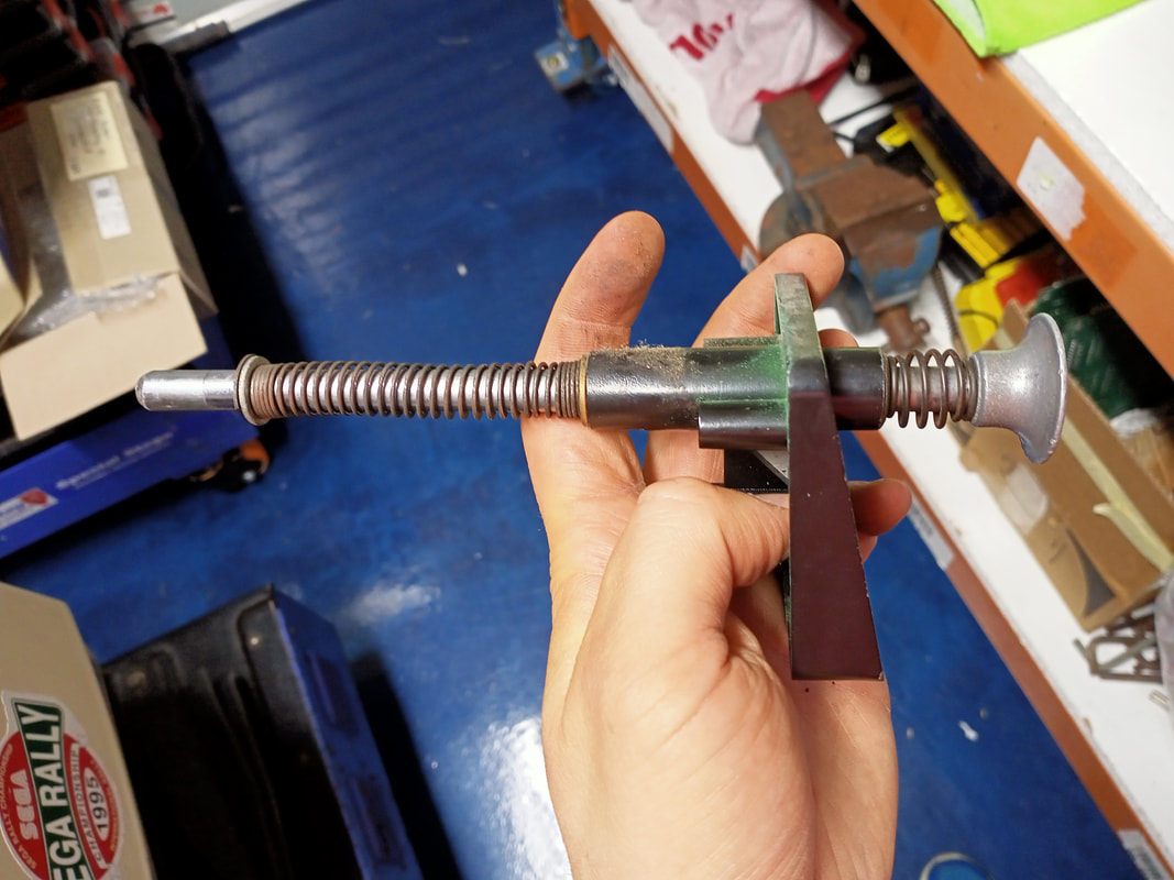
The trough eject assembly was not able to push balls from the trough into the shooter lane. The balls would get pushed upward a little, but not enough to get them over the playfield wood and onto the playfield surface. I tried actuating the ball feeder arm manually and found it was very stiff.
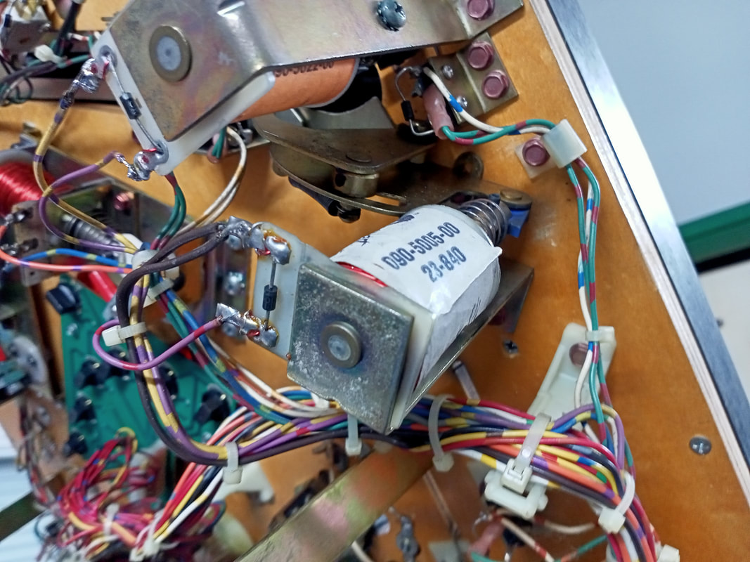
Trough eject coil assembly.
Despite what most people would tell you, there are actually some assemblies in a pinball machine that you should lubricate with oil. Any assembly with a pivot point (such as this ball feeder assembly) should be lubricated as a regular maintenance activity. While not mentioned in the Data East manual, the assembly is the same as the Williams ball release mechanism, so the same lubrication requirements apply. Below is the excerpt from a Williams manual: 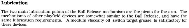
After a few drops of 3-in-1 oil and working the oil in, the assembly started to loosen up nicely. Testing the ball feeder coil in coil test showed that it now had plenty of power to serve the ball into the shooter lane. Rubber ring replacement
Changing the rubber rings would not normally warrant a whole discussion section but there are so many issues with the rubber map in the game manual (page 32), some extra commentary is warranted to correct the mistakes.
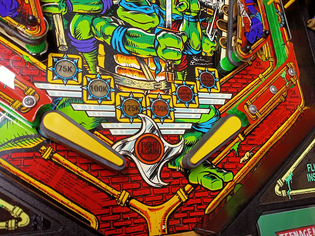
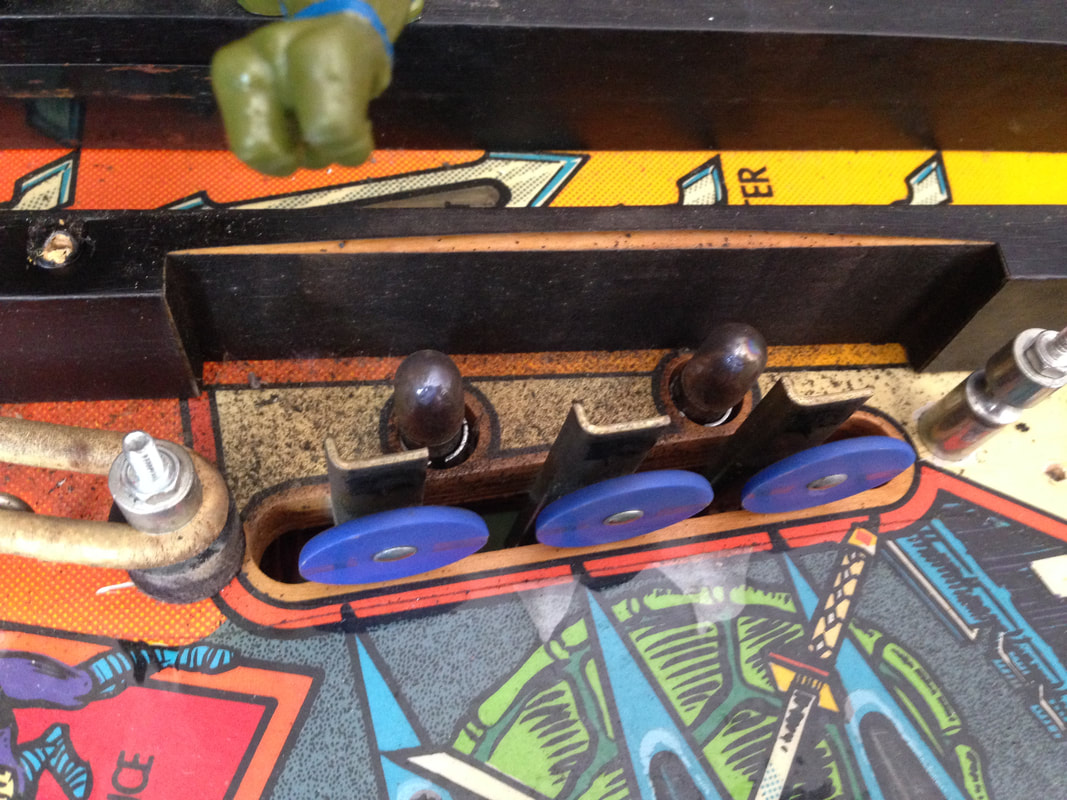
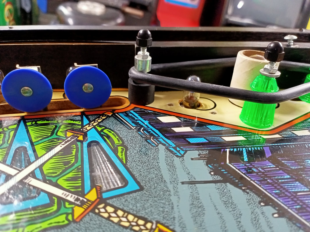
The manual specifies you need two extra large (4-1/2") rubber rings for the very back of the playfield, behind the pop bumpers. These rubbers go over double posts and stretch over five posts in total. It's a long stretch, and the 4-1/2" rubber rings are extremely tight when stretched over all of the posts. In my opinion 4-1/2" is way too small for this location. Instead, I used two 5" rings and these are a much better fit, while still being very snug. 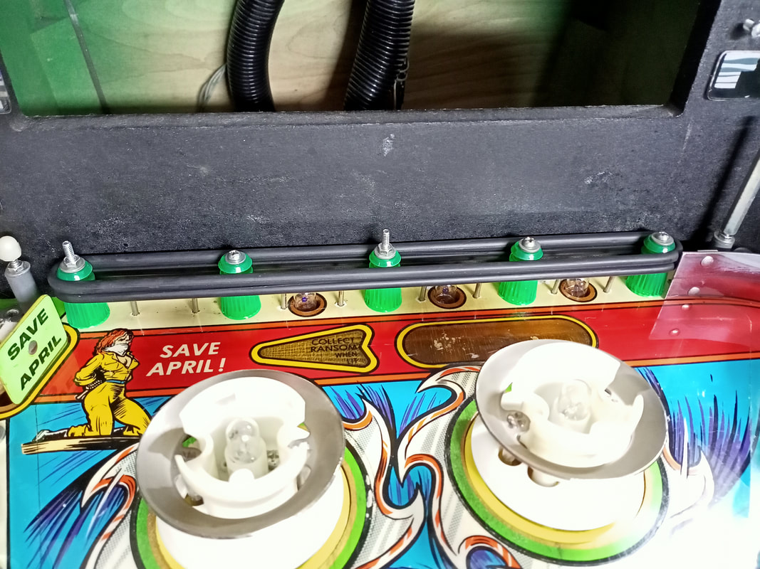
Two 5" rubber rings installed over posts at the rear of the playfield.
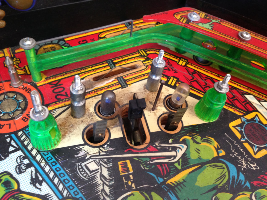
There are multiple metal posts around the playfield with rubber rings installed around them. Data East games typically use short, 1/2" rubber post sleeves on these metal posts, below where the rubber ring sits, to provide extra protection to the post. The manual indicates four are needed on the game, but three of the positions indicated on the rubber map are invalid for this kind of rubber sleeve. For example, two short post sleeves are labelled on either side of the Michaelangelo targets. However there is only a single post on the left side of the targets. There is no post on the right side at all. Moreover, a short rubber post is useless here because this is a full-sized, straight post. A standard post sleeve belongs here instead of a short one. If you want to do it properly and install these short rubber sleeves on each metal post with a rubber ring, you'll need 10 of sleeves in total (RTBB, PSPA). Correct installation locations are shown in the pictures below. A 2" ring is suggested by the manual across two posts adjacent the captive ball. A 2" ring fits too loosely here, so I installed a 1-1/2" ring instead. Much better fitment. Another omission in this area is the lack of two 3/8" OD post rings on either side of the captive ball. 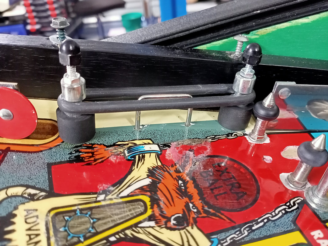
1-1/2" rubber ring installed to the left of the captive ball.
There is a mix-up on the rubber map legend labelling, too. The "H" size on the rubber map should actually be "A", as A refers to the 7/8" post sleeves in front of the ramp entrances. Five of these posts are needed in total, instead of the three indicated on the rubber map. Three go in front of the ramp entrances, one goes next to the Michelangelo targets, and one is adjacent the spinner. I had some yellow posts spare so I decided to use those in these locations. Yellow goes well with the greens, yellows, oranges and reds on the playfield, I think. 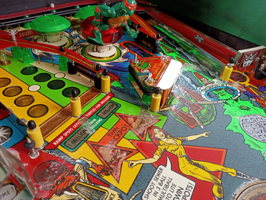
Positions of rubber post sleeves on the playfield.
I actually experimented a bit and installed two rubber rings kits to see how both black and white rubber looked on the game. In the end I decided black was a better look on this machine, but some of the final photos taken of the machine were taken while it still had the white rubbers on. Turtles is one of those games which can look good in either colour!
Turtle figurine placement
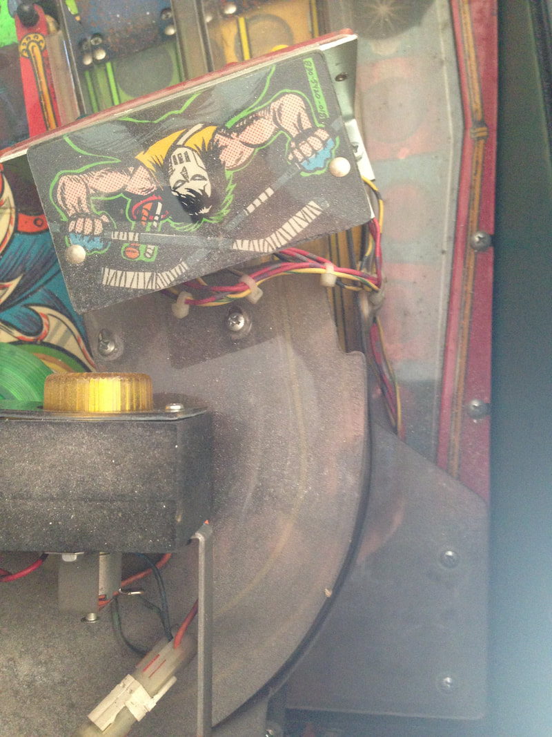
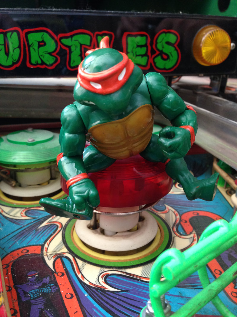
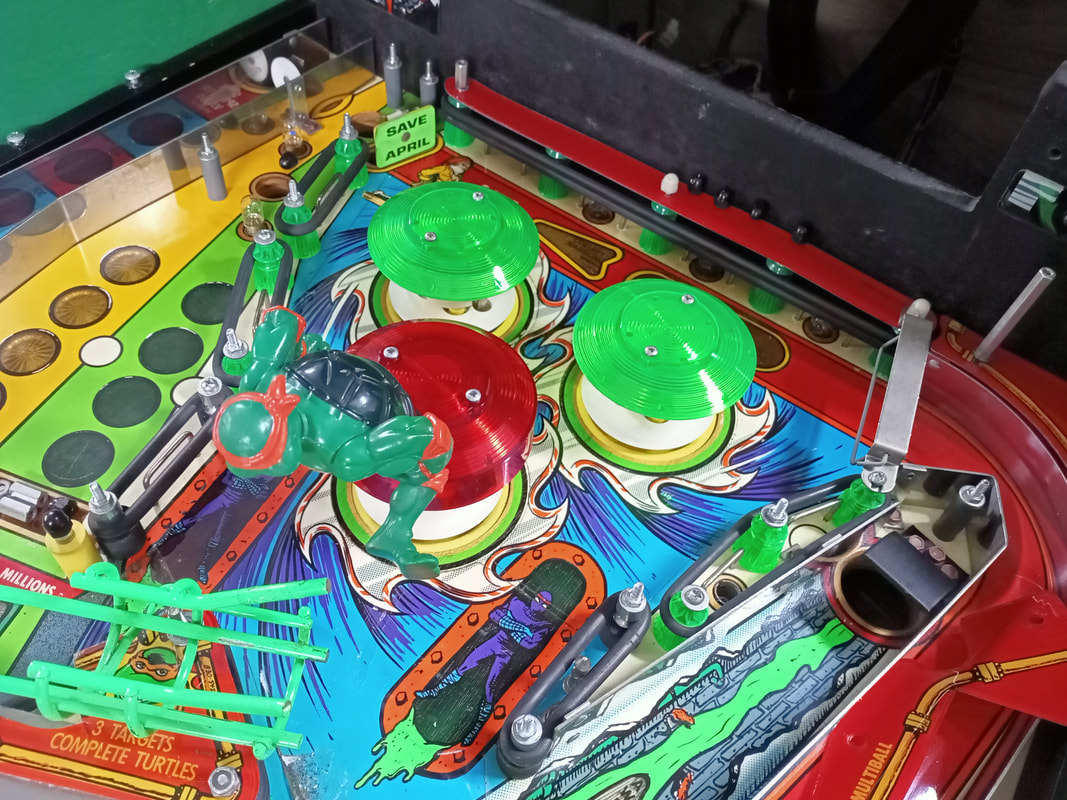
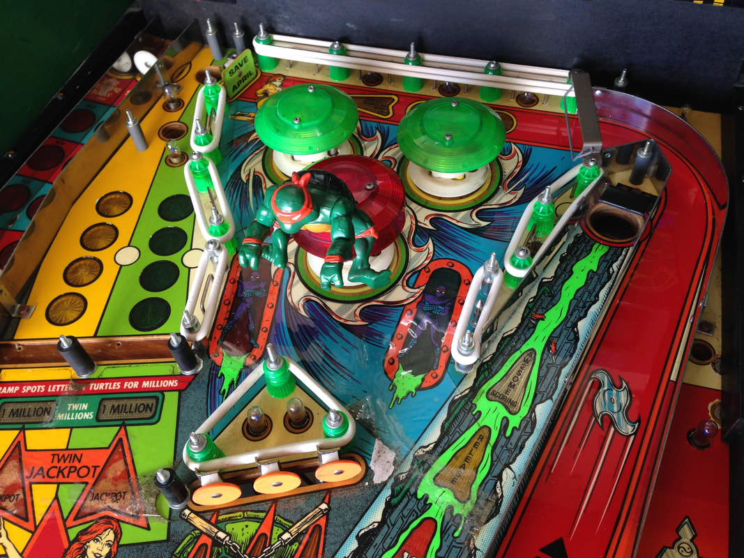
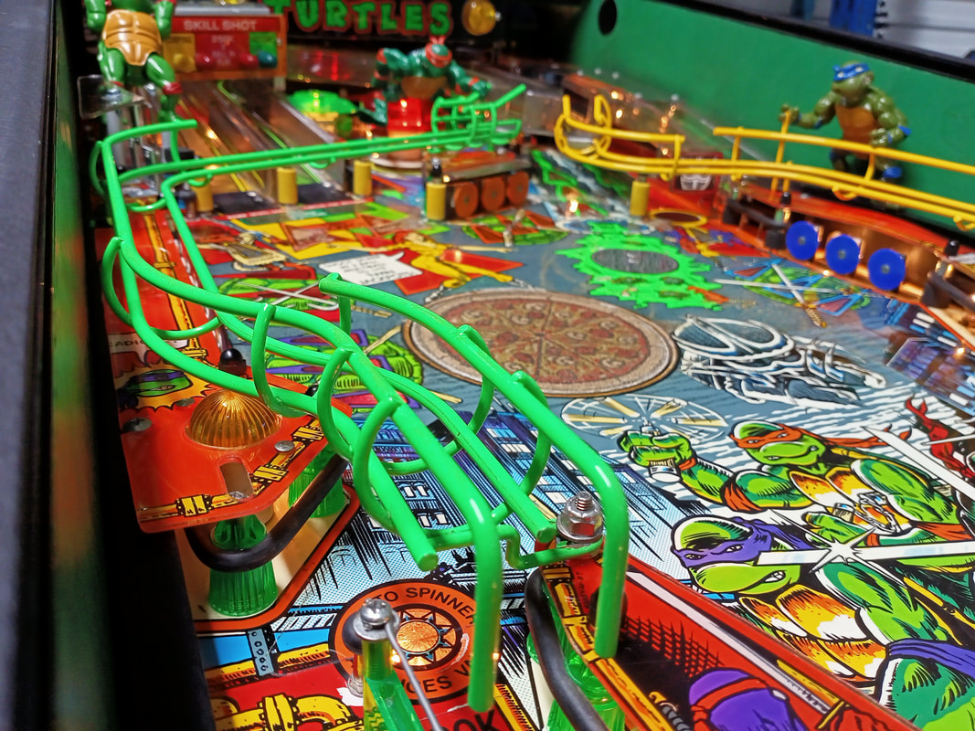
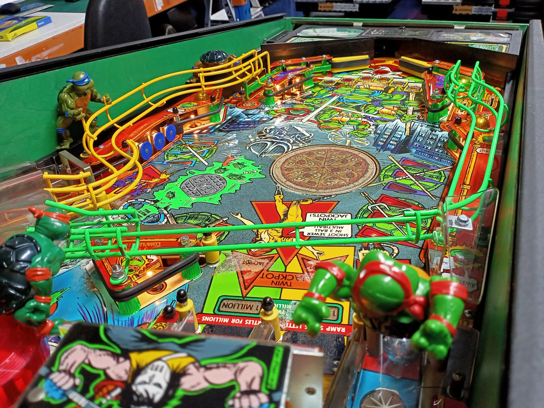
Every time I see a picture of someone's Turtles machine, it seems to show each of the turtle figures in a different position or pose. There is actually a very specific way in which each turtle should be mounted to the playfield, but the most important rule is that only Leonardo (blue) should have his hands clasped around the wireform ramp. None of the other turtles should be holding any nearby ramps, wireforms or plastics.
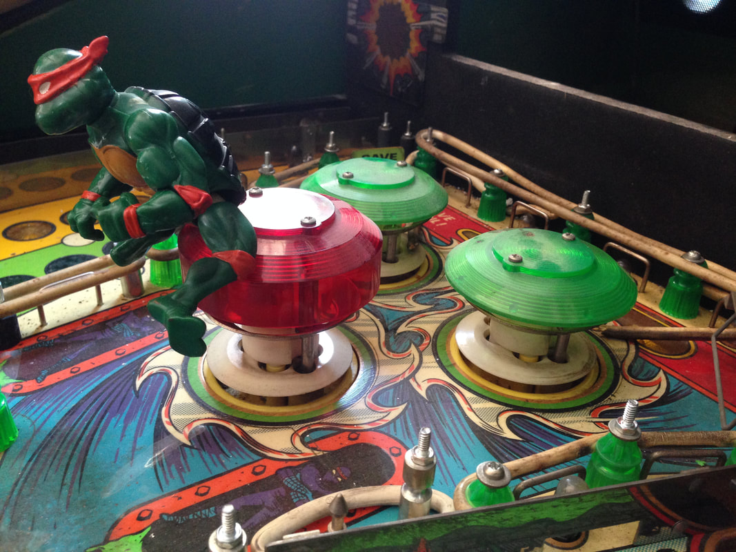
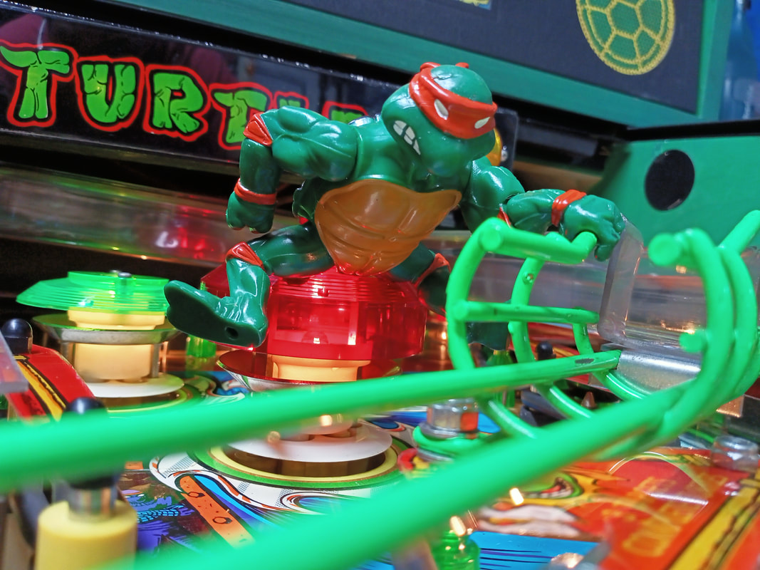
Raphael (red) sits on top of the captive ball assembly and isn't actually near enough to any other playfield components to grab them, so he is easy. Originally he is positioned in a forward-leaning position, but I like to move him so he's bending over backwards trying to break open the playfield glass! Way more interactive! 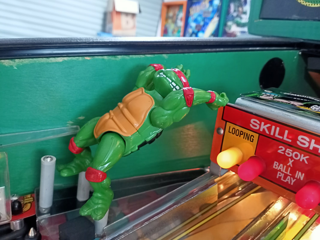
Raphael doesn't like being flattened by the playfield glass!
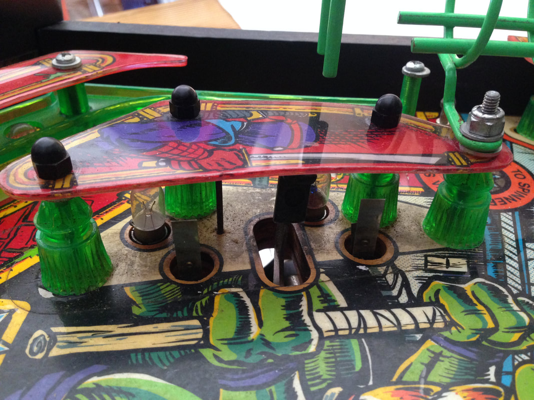
Michaelangelo (orange) sits on top of the pop bumper. I see some people say that his hands should be grabbing onto the wireform ramp in front of him. The pictures on IPDB even show him in this position. However, my advice is not to do this. The Michelangelo on this machine had literally lost his legs - they had disconnected at the hip socket - from the vibrations of the pop bumper. His legs and arms simply snap back into his body, so make sure they're tight. So keep in mind if you make him hold onto the ramp, you may be doing leg and arm surgery regularly. If anything, try and make him sit as upright as possible in order to balance the pop bumper's centre of gravity. Having him lean forward makes the pop bumper's rod and ring assembly tilt forward due to his weight. 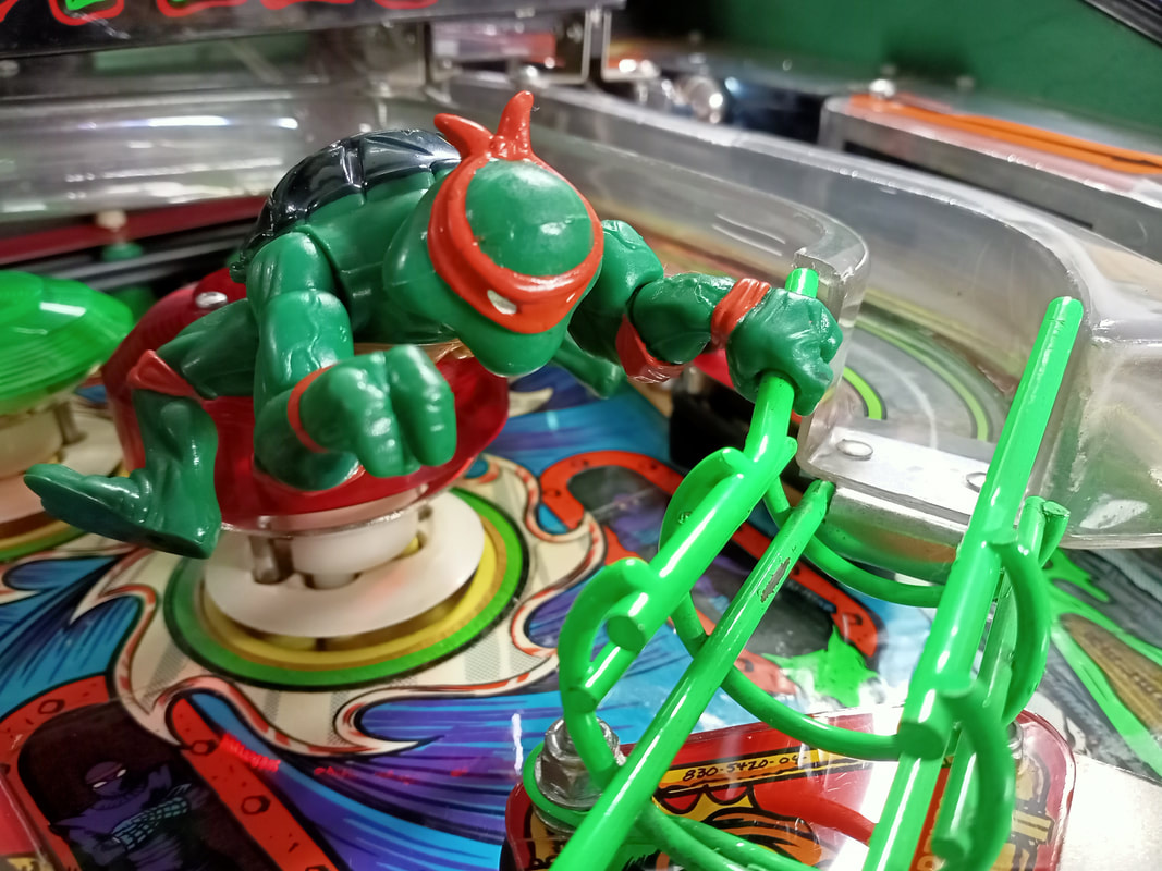
Michaelangelo can be made to hold onto the ramp, but his legs and arms may disconnect!
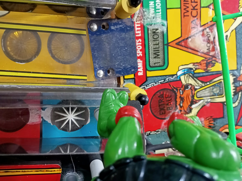
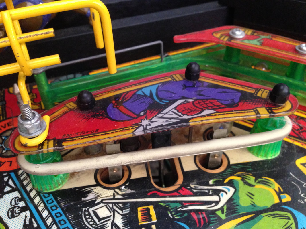
Donatello (purple) is another 'gotcha'. He looks just like he is supposed to be holding onto the yellow wireform ramp, because it is just in front of him, and his arms can be moved to grab the wireform easily. However, if you attach him to the ramp, there will not be enough clearance for balls to pass. His hand needs to stay in mid-air. 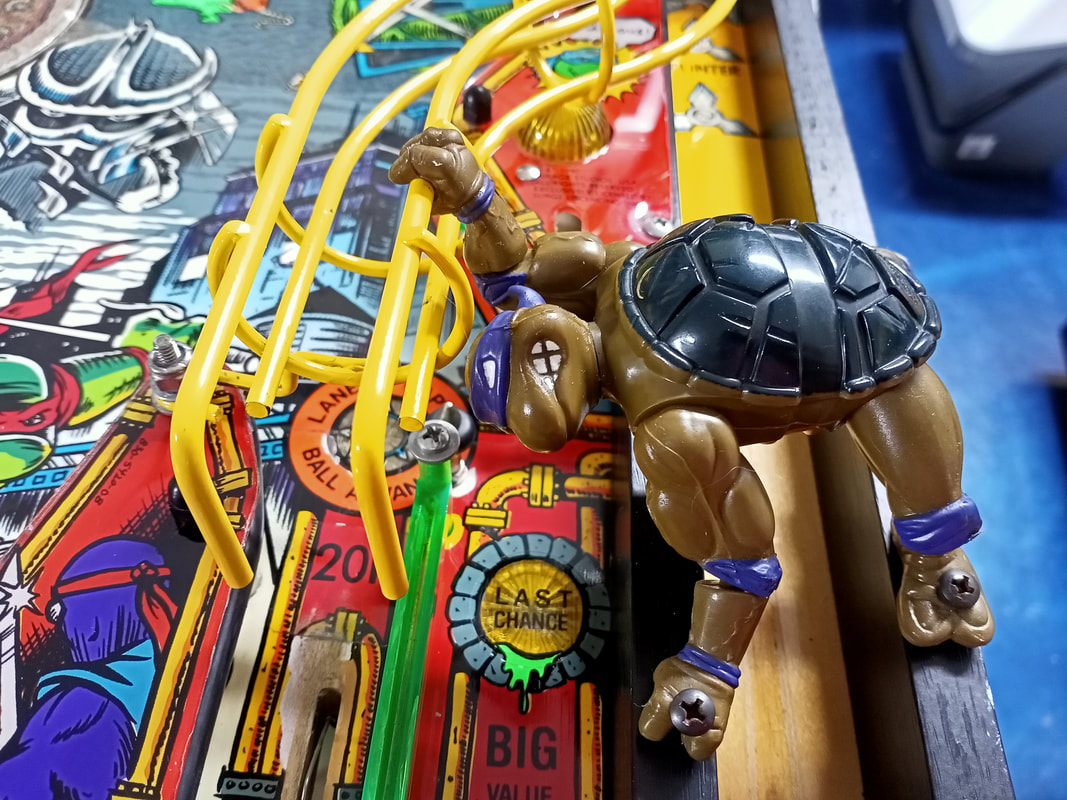
Incorrect Donatello placement. He is NOT supposed to be grabbing onto the ramp.
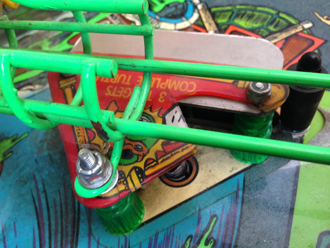
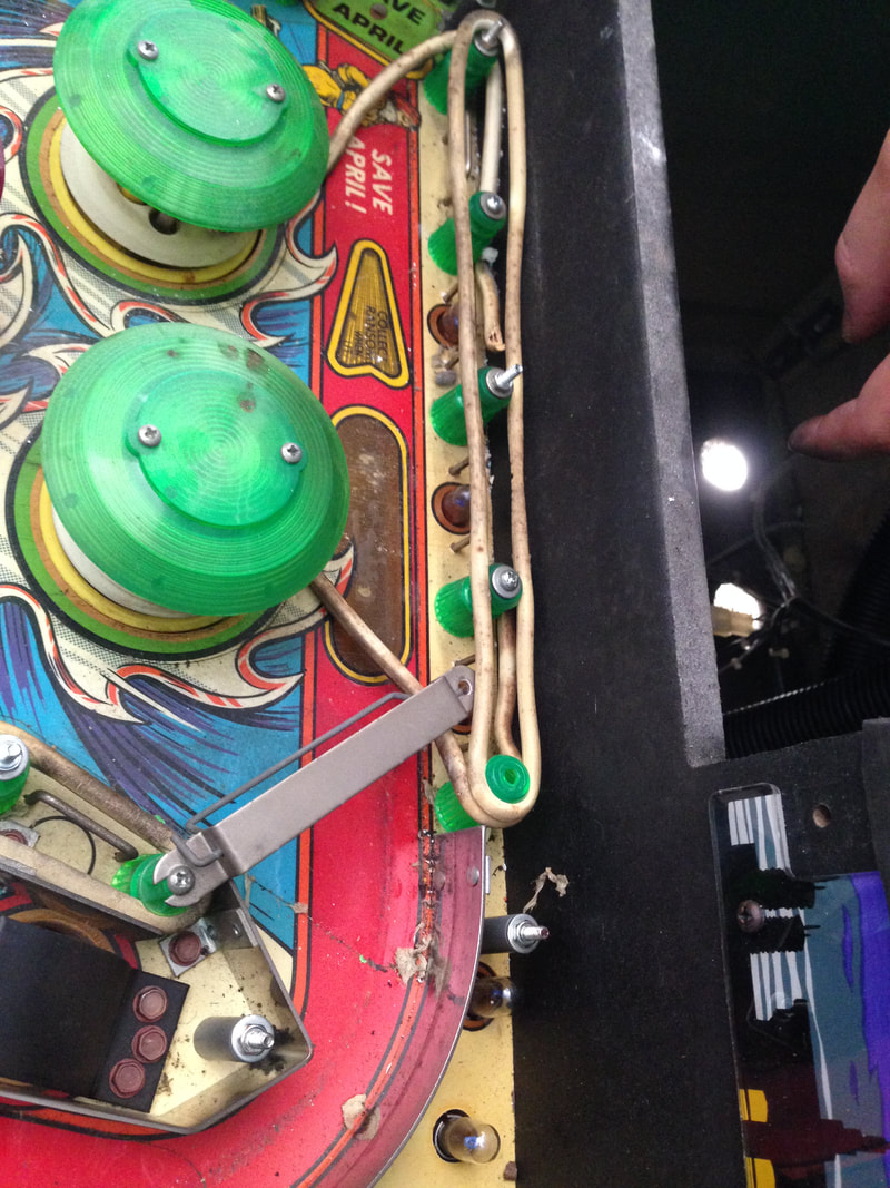
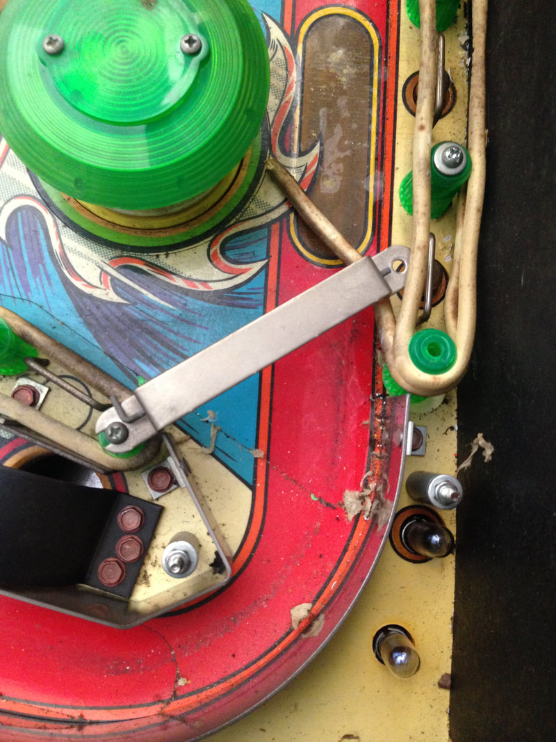
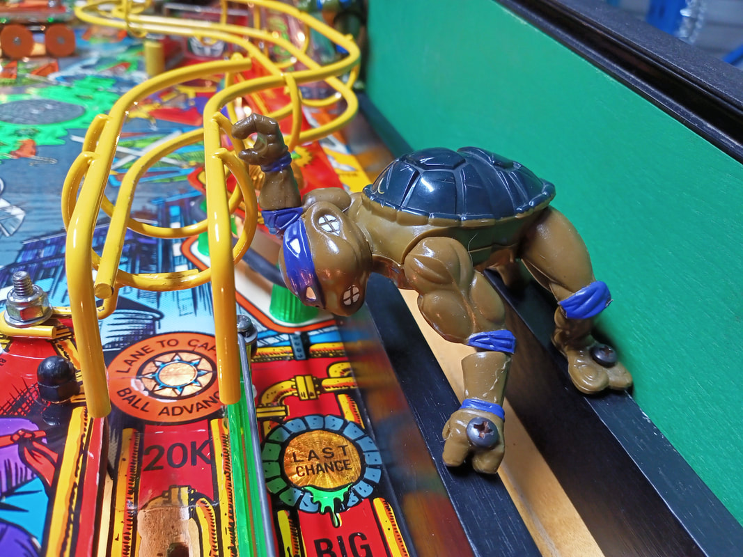
Leonardo (blue) is the only turtle who is supposed to be holding onto anything. His right and left hands can grab onto the wireform as there are handholds here just for this purpose. 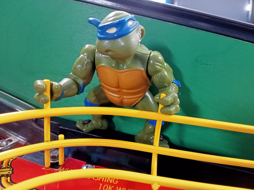
Leonardo grabbing onto the wireform handholds.
Cabinet grille replacement
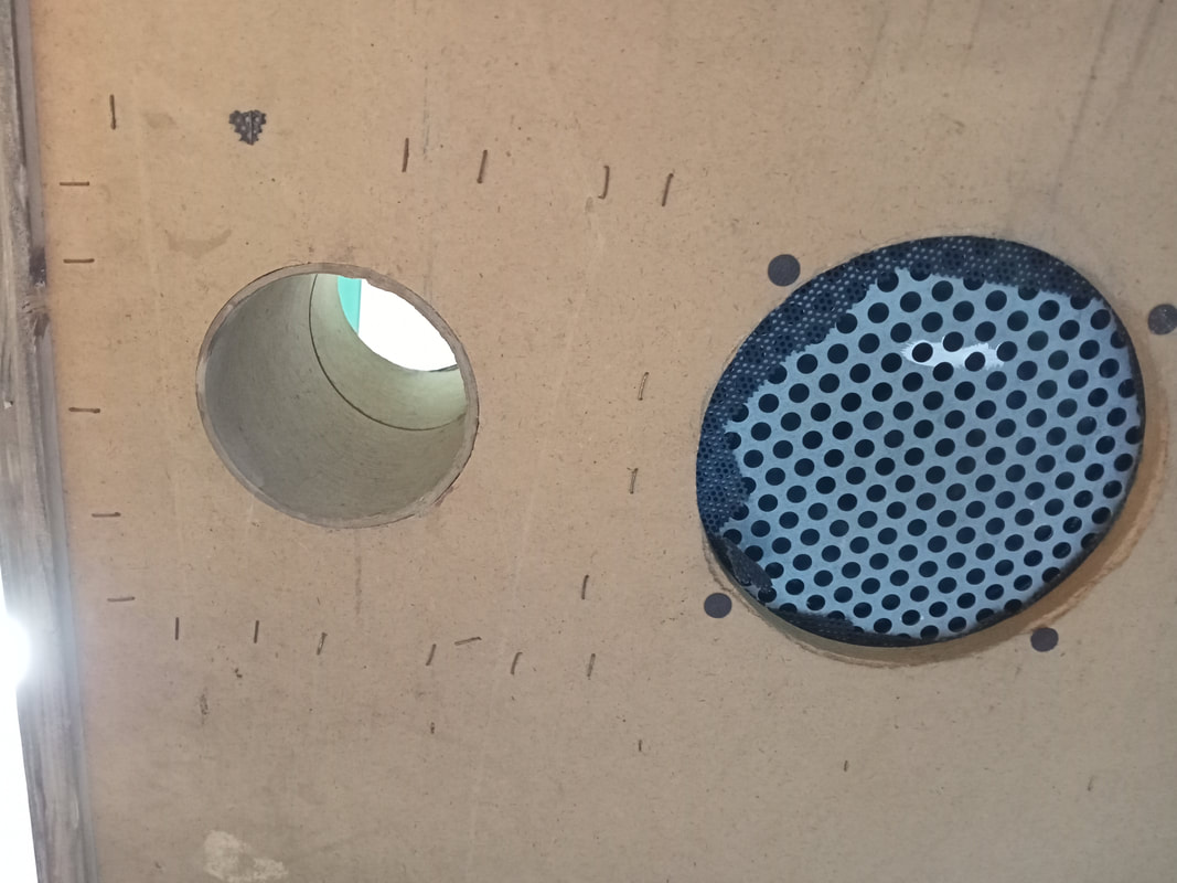
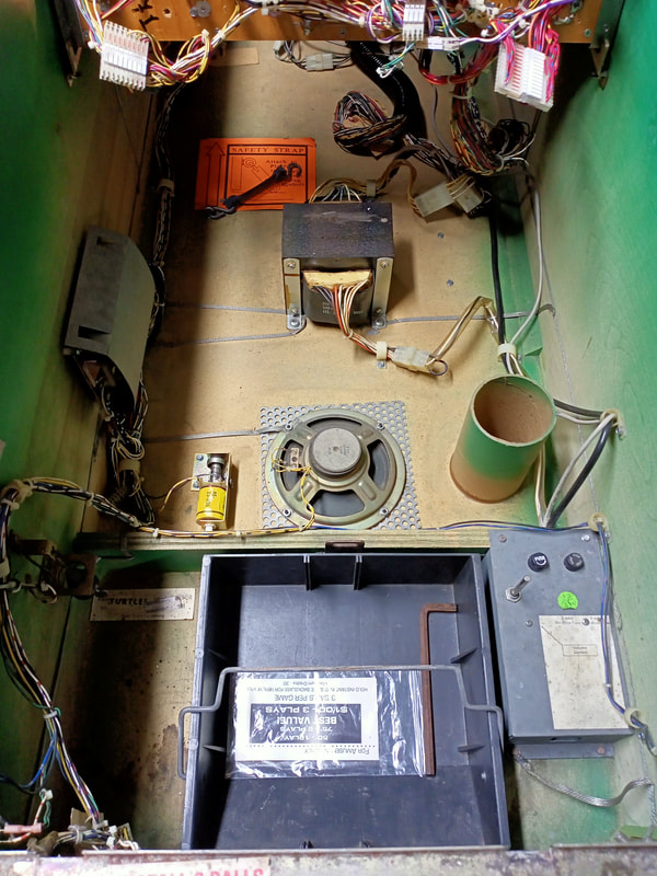
Most people who have not owned a Data East game before get confused when they first open the cabinet and see a vertical cardboard tube sitting next to the subwoofer. I did too! This tube is basically a part of the sound system, and provides a port for the subwoofer pressure within the cabinet to equalise. It does actually make a subtle difference to the bass response, believe it or not.
Of course, this means there is another hole in the base of the cabinet. Normally this hole is covered by a speaker grille plastic. However, the grille on this game was long gone. All that remained were the staples that originally secured it. The original piece is about 7x7", but I cut a slightly smaller piece out. These speaker grilles are pretty much the same between Williams, Data East, and Gottlieb games, so it's good to have a few spares handy (PSPA).
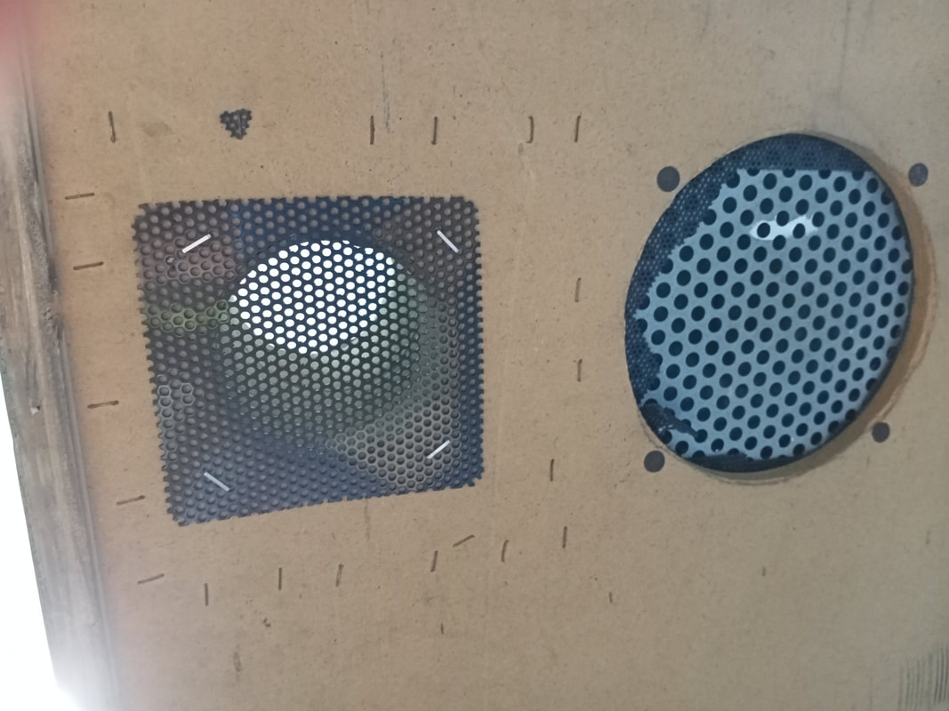
Funnily enough, the speaker grille covering the subwoofer itself had broken at some point, and someone replaced it with a metal grille (cool). Except, for some reason, they never removed the original, broken plastic grille before installing the metal one (not cool). Why wouldn't you do this while you're there installing the new one? It took me all of two minutes to do! Never mind; it's done now. 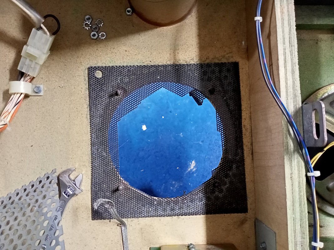
Please replace broken speaker grilles!
Power input box assembly fuse holder replacement
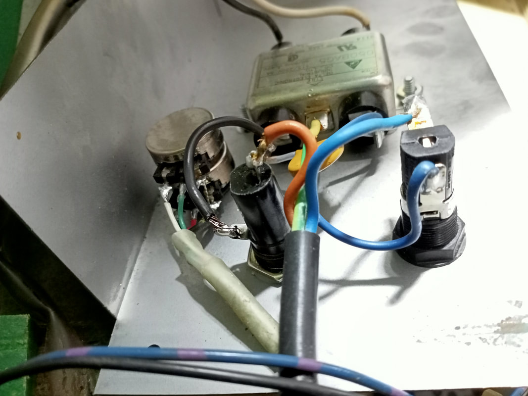
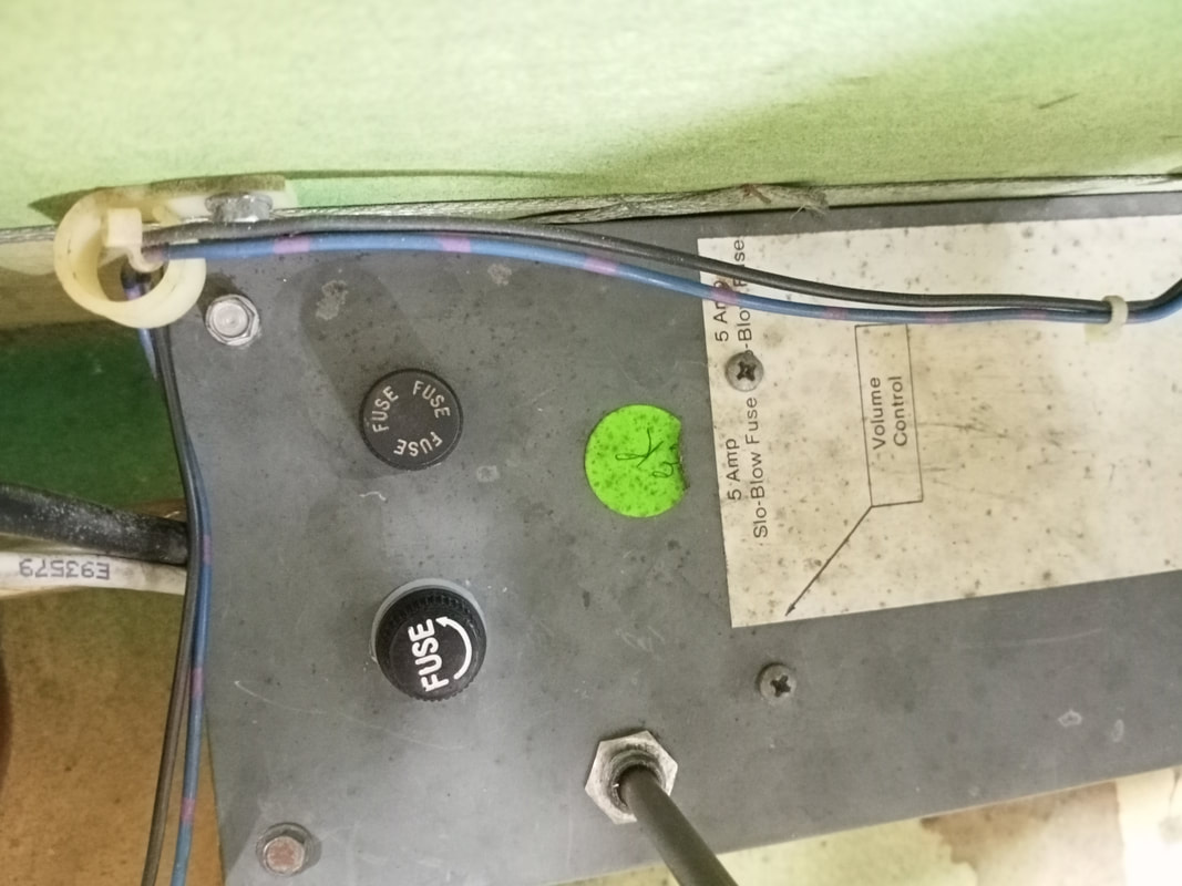
The power input box is located inside the cabinet on the right side, adjacent the coin box. This assembly houses the line filter, power switch, fuses, and a varistor. The one weird thing I noticed about it was that, instead of two fuse holders being present on the topside of the box, I saw one fuse holder and an empty hole. Hmm.
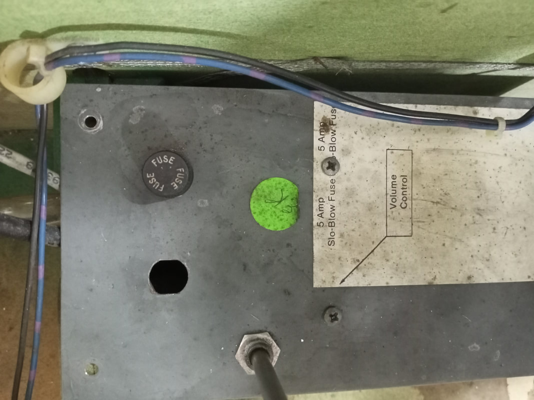
Power input box with a single fuse holder and an empty hole.
The game can't turn on without a fuse here (unless the fuse has been bypassed), yet this game turned on without issue. So I decided to open it up and see what's going on, fully expecting some kind of hackery. 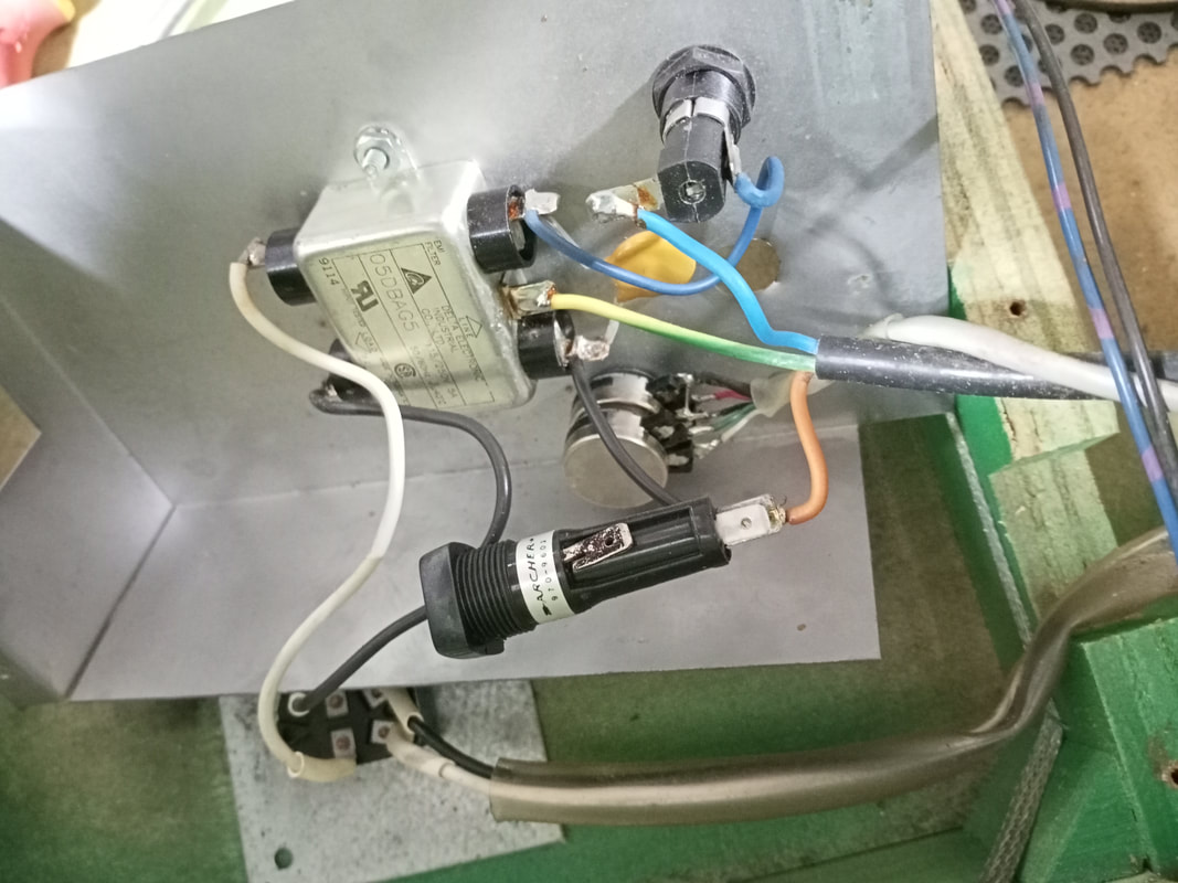
Large fuse holder installed which did not fit into the mounting hole.
But, what I found was that there wasn't too much hackery, just a poor repair job. There was indeed a fuse present here like there should have been, but it was housed in a very large fuse holder which was tucked inside the power box and inaccessible from the outside. The original fuse holder had been replaced with a massive one which did not fit into the original mounting hole on the top of the box. The mounting hole is about 11mm in diameter, whereas this fuse holder was at least 15mm in diameter. Plus, it was very long, so it actually touched the cabinet base when it was held in position as if it were installed. This was probably a case of repairing the game with whatever parts you had on hand, even if those parts were a too-large fuse holder. This fuse fused the active wire, which is probably not a good fuse holder to keep shoved in the power box as it is easy for the active to short against the multitude of metal objects in here. Especially since there was nothing to insulate the fuse terminals from other components. Best course of action here was to replace the fuse holder with a more appropriate one. Unfortunately, original style panel mount fuse holders are difficult to come by. The mounting hole is quite small (~11mm) and is a weird shape with flanges on either side. A couple of different replacement holders are locally available (Jaycar) but require a larger diameter hole. I had one spare fuse holder in my toolbox which was 14mm in diameter. So, I grabbed my 14mm drill bit and went to town on the old mounting hole. It didn't take long to enlarge it to the right size, and then the new fuse holder could be easily inserted. This one was similar in length to the original fuse holder, so there was plenty of space around it and below it when it was installed, and no risk of shorts against other components.
Replacement ball guide wireform
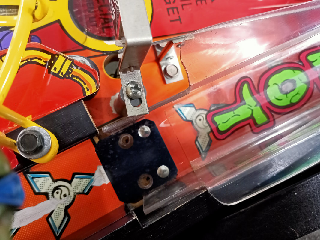
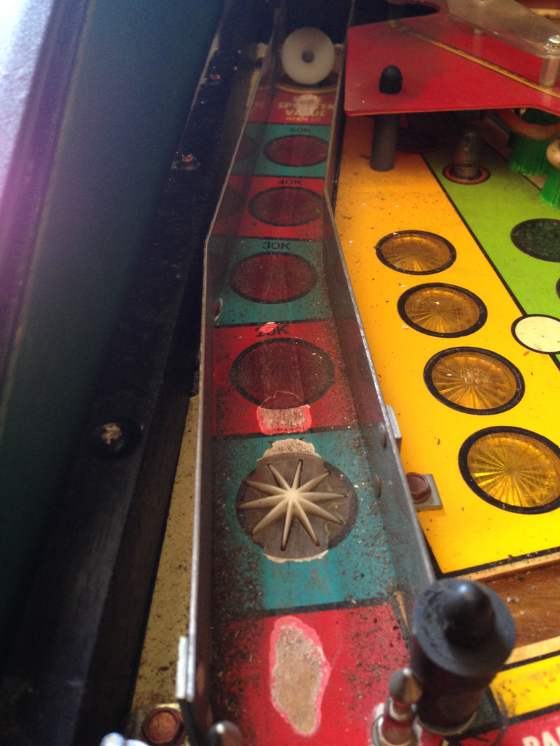
The lane guides on Data East games consist of a moulded plastic ball guide (part no. 550-5037-11 for left and 550-5038-11 for right) with a small piece of wire where the ball drop from the wireform ramp is. This piece of wire is meant to prevent balls from skipping over the plastic ball guide when dropping from the ramp. However, the wire wsa missing on the left ball guide. Very frustrating to lose balls down the left drain after a bad bounce from the wireform ramp. I have no idea what the part number for this piece of wire was, so I figured it was easier to make up my own than try and find one to buy.
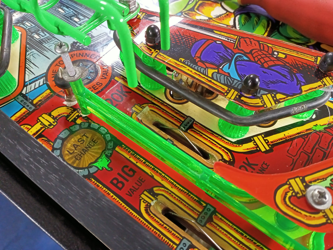
Plastic ball guide with missing wire piece on top.
The best thing to use for making small wireforms such as this is stainless steel fencing tie wire (Bunnings). It's strong and resists corrosion, yet it is still malleable enough to bend in a vice or with pliers. The Bunnings product is also 1.6 mm in diameter, which very closely matches the original wire. You'll need a piece about 10 cm long for this application (the one below is a little over 10 cm but I cut it shorter after bending). The wire I bought came in a roll, so I flattened it out in the vice and hammered it on an anvil to get it as straight as I could before bending it. 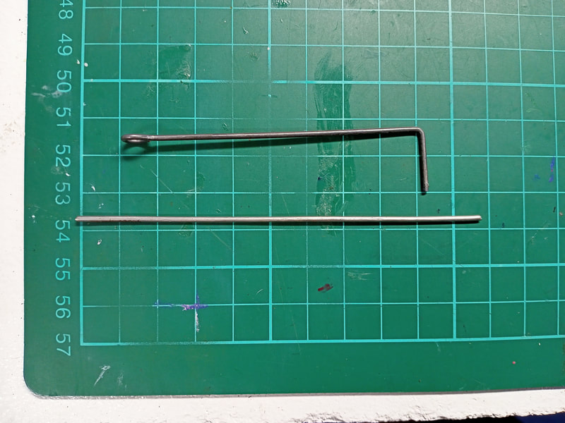
Original wire piece above, and straightened piece below prior to bending.
I used the original wire piece from the other ball guide as a template, and simply tried to replicate it. I used pliers to bend the end of the wire into a loop for the screw, then placed the piece in a vice and bent the 90 degree angle into it. 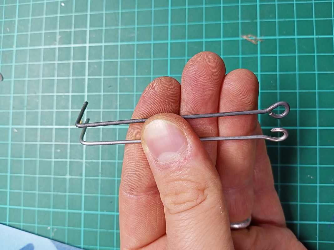
Original wire piece at top, and newly fabricated one below.
I think the end result is pretty good, and looks almost exactly the same as the original. It certainly does the job of blocking balls from falling into the left drain lane, so that is good enough for me! 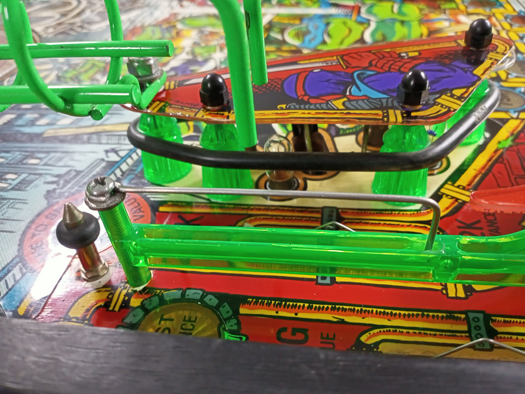
Newly fabricated wire piece installed on lane guide.
Dot matrix display misalignment
The dot matrix display behind the backglass was not positioned correctly. The display was too low, resulting in the bottom few lines being unreadable. The right side seemed to be a little lower than the left side, also. This needed to be fixed so everything on the display could actually be read during a game!
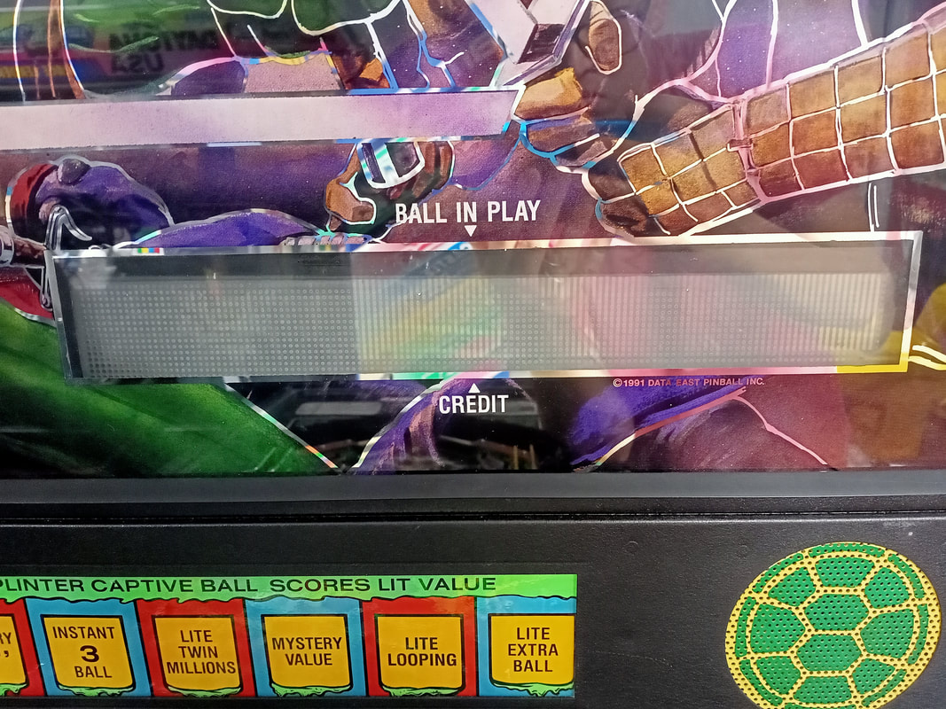
Original misaligned position of the display.
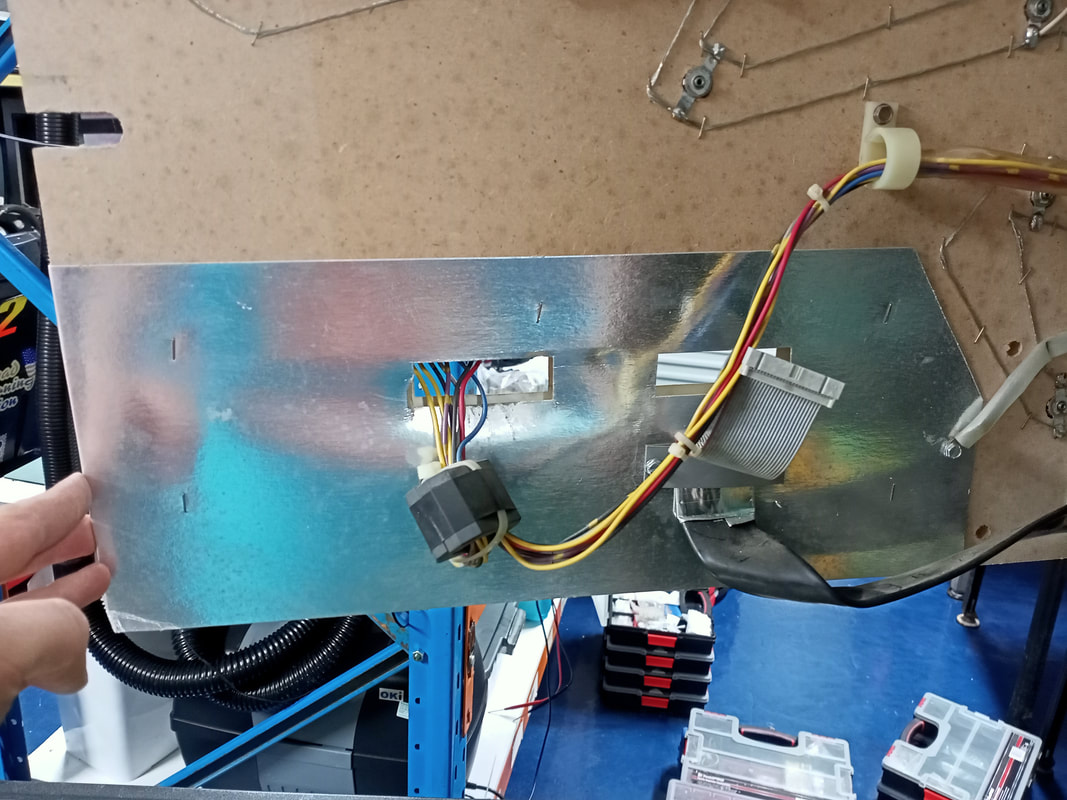
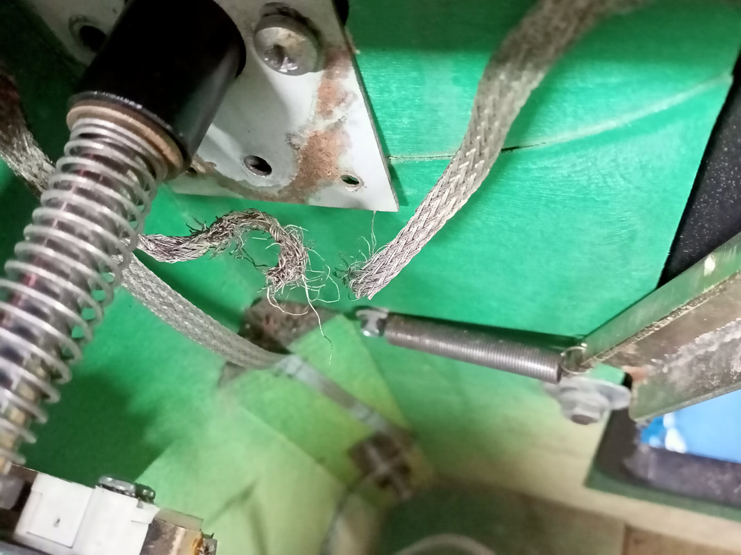
I'm really not quite sure how the display ends up so low in the backbox. The only real way to "lift" the display is to reposition it on the insert panel, or raise the position of the entire insert panel. I opted for the second option, as the panel scraped on the top of the speaker panel at the right side when opening. This suggested to me that the panel itself was too low. The panel can be removed from the game by unplugging two connectors for lamps and flashers. Then, the ground braid that runs across the rear of panel also needs to be freed from the backbox. There are a couple of staples that hold it in place once it enters the backbox proper; simply remove these staples and lift the braid out. It can be stapled back into place later. Five woodscrews attach the panel to the hinge, so remove them to finally free the panel. 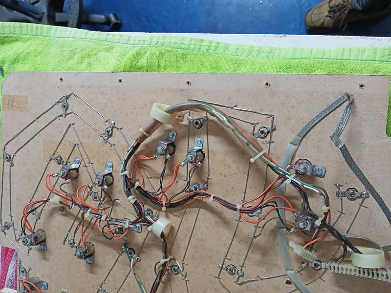
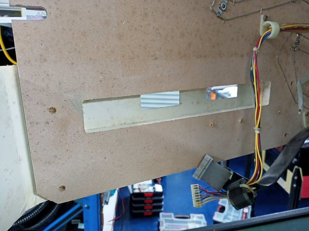
Original screw holes on the insert panel.
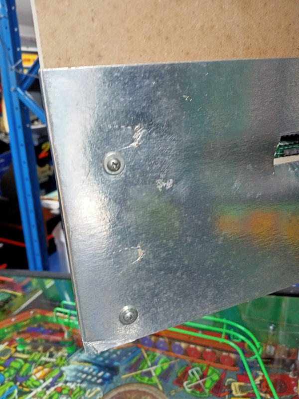
I simply created new holes approximately 10 mm from the original screw holes. Remember the position in which you want the panel to sit. If you want the panel to sit lower, the new screw holes need to be higher than the old ones. If you want the panel to sit higher, the new screw holes need to be lower than the old ones. So, I made all of my screw holes below the old ones. Be sure to pre-drill. There is also one other piece of hardware you need to move when moving the insert panel. The "catch" for the insert panel latch. If you are moving the insert panel higher, the catch needs to be moved upwards. Be sure to align the position of the catch with the cut-out in the panel. I moved the latch upwards just enough to create a fresh hole for the mounting screws. After this, the latch was positioned perfectly to sit on the middle of the "catch" screw.
And that was all that was needed to move the insert panel upwards slightly. However, there was still the problem of the display drooping slightly on the right side. The bottom row of the display was only barely visible on the right as a result. For some reason, there still appeared to be some issue with how the display was mounted. 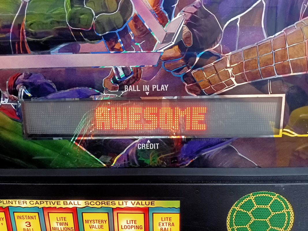
Position of the display after lifting the insert panel. Still a slight drop on the right side.
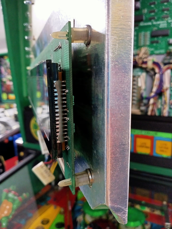
The cause of this appeared to be the nylon circuit board mount on the top right corner of the display. This mounting tab had snapped, and was drooping slightly under the weight of the display. Easy fix! Just replace the mounting tab, right? 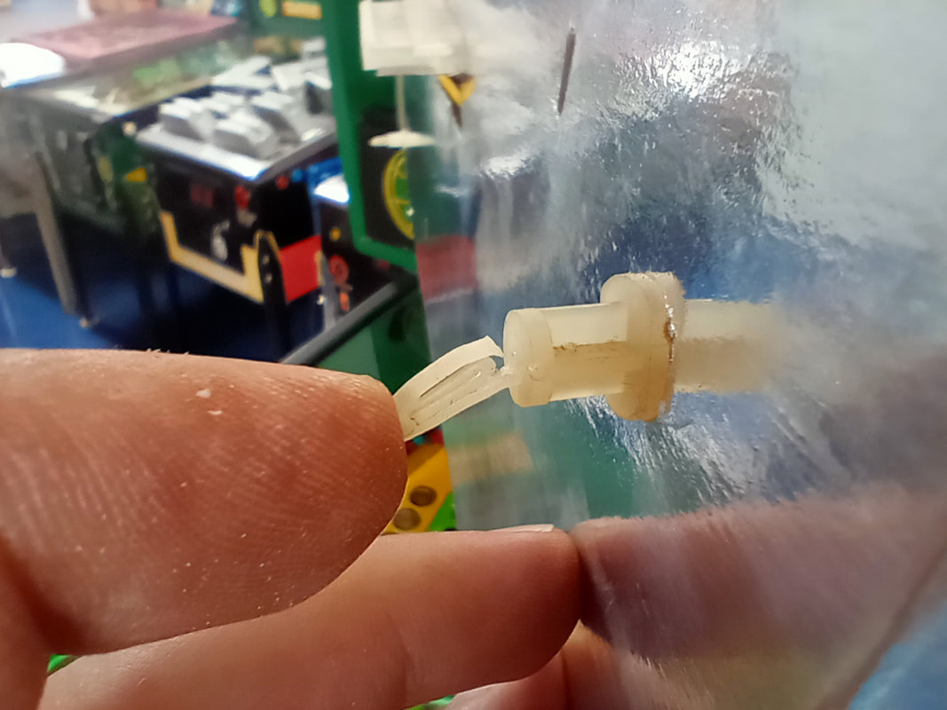
Broken circuit board mounting tab at the top right corner.
Not so fast there, Jim! The first issue we have is getting to the rear of the mounting tab so we can remove it. The display is mounted to a piece of cardboard with a conductive coating on it, which covers both the front and rear side of the insert panel. It is stapled in place, so you'll need to pry the staples off, and unscrew the grounding strap and ribbon cable bracket, in order to peel back the cardboard. Once that's done, you'll have access to the holes in which the mounting tabs are installed.
Now, you'd be forgiven for thinking that Data East used proper mounting tabs which were screwed or bolted into position. That would be way too easy! Data East cheaped out a bit when it came to these circuit board mounts. Instead of being screwed into the timber, they are knurled, so that they bite into the timber as they are inserted. These can only be removed by bashing them out. I used a small piece of wood and a mallet to gently tap them out. 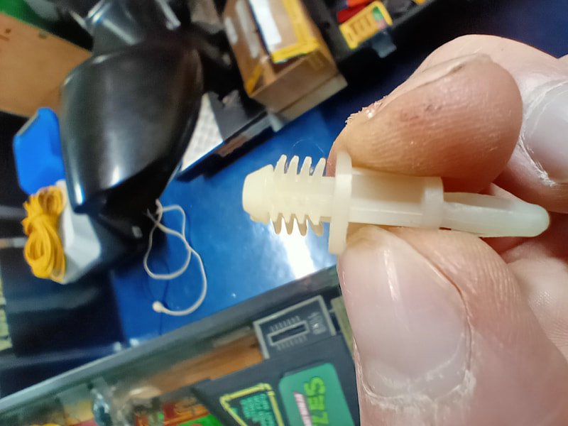
Knurled circuit board mounting tab.
I had a number of circuit board mounting tabs in my spares kit (RTBB), however none of them were the same knurled style. I decided to replace them with screw-in mounting tabs. These would be easily removable and replaceable in future. I had to saw these mounting tabs down a little as they were slightly longer than the original tabs, but this was neatly done with a hobby saw which worked quite well. 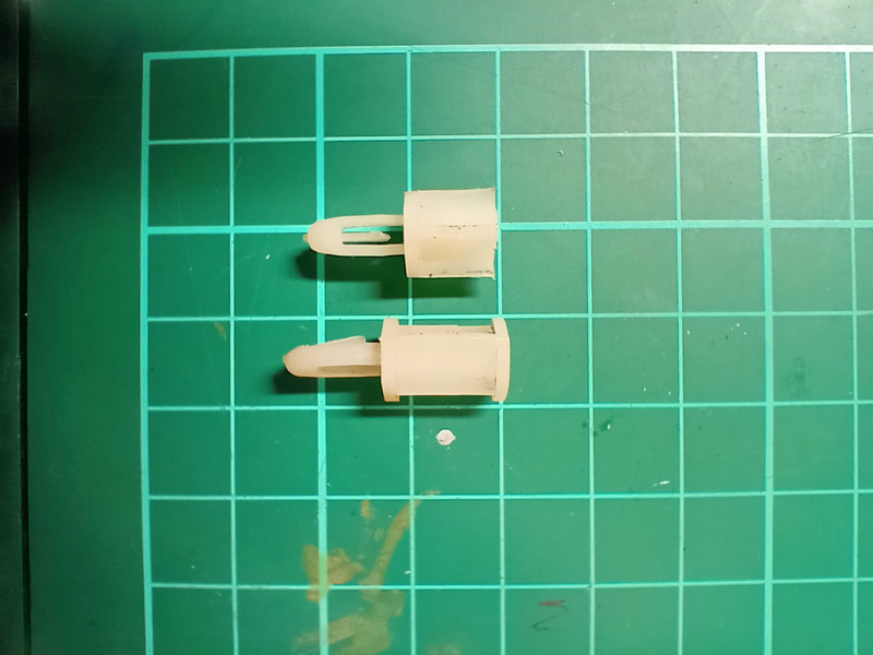
Replacement circuit board mounting tabs. The top one has been cut down to match the size of the original ones. The bottom one is yet to be cut.
The holes for the original mounting tabs were much larger than needed for the screws which would hold the new mounting tabs into position. So, I pushed the new tabs up as far as possible into the holes to rectify the issue of the display drooping on the right. I used washers on both the front and rear of the panel to provide some extra support to the mounting tab. This worked well, as the cut-down tabs were the perfect size to match the old ones. Of course, once I did the top right mounting tab, I also had to do the bottom right tab so that I could align the two tabs with the holes in the display. The display installed smoothly and sat nicely on the new mounting tabs.
The end result was that the display was now fully visible through the backglass display window. There was still a slight droop to the right side, which I had been unable to fully rectify. The next step to fully fix this would be to make new holes for the circuit board mounting tabs slightly above the original ones. This would give the right side the very slight lift needed. However, as far as I was concerned, the display was fully visible now which was the most important thing. A definite improvement over the initial situation. 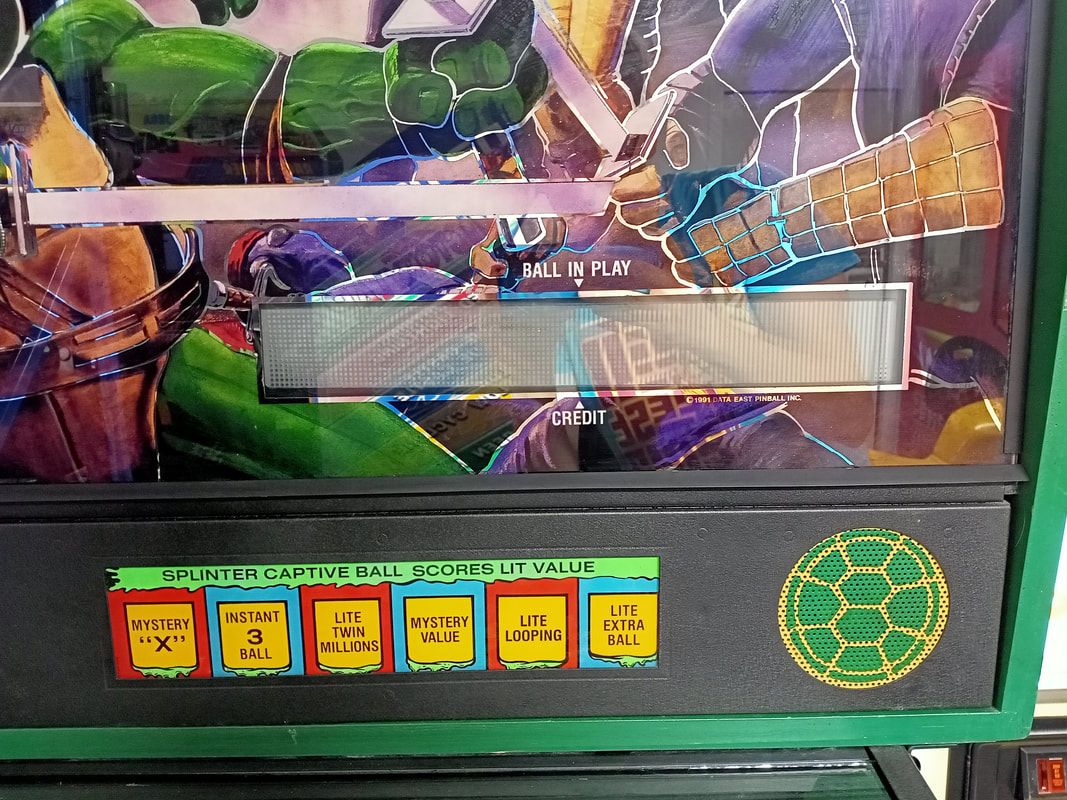
Display after replacement and repositioning of the mounting tabs. Bottom row now fully visible!
Plastic ramp repairs
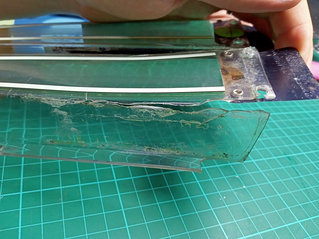
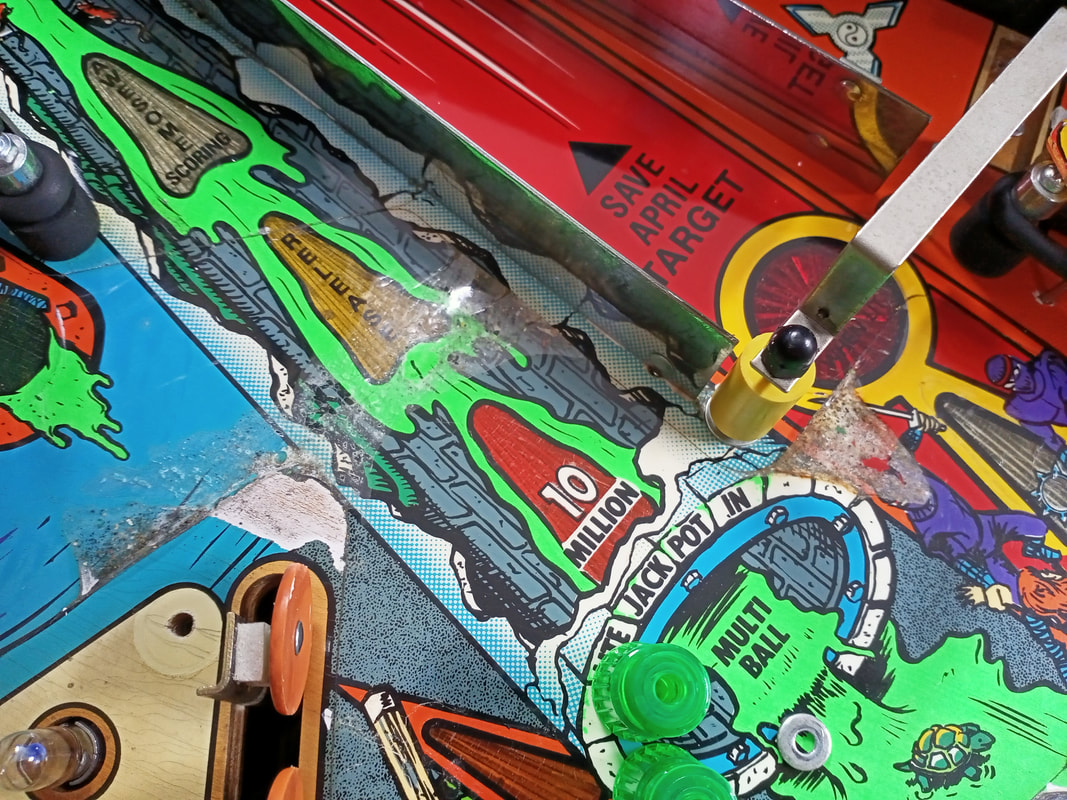
I don't think there is a single Turtles game in existence which has an intact plastic ramp. This ramp gets absolutely belted as a result of some poor playfield design choices. The posts at the ramp entrances are supposed to protect the ramps from ball impacts, however the ramp entrances are quite wide, and a ball that glances off the edge of one of the posts can bounce directly into the side walls of the ramp. Shots from the right flipper to the targets on the left side of the playfield can also be deflected towards the side wall of the ramp, particularly the right (green) ramp entrance. Combine the above with the overpowered flippers that Data East had a habit of using, and you get smashed ramps. The video below shows an example of how the ramps get so damaged.
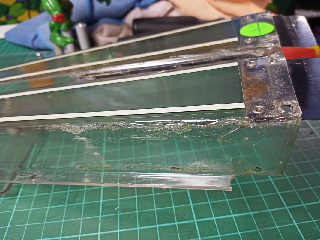
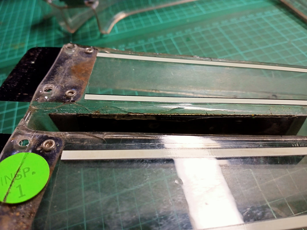
The damage most often occurs to the right (green) ramp. The right side wall of the ramp is the most exposed as it is on a greater angle to the rest of the playfield than the left ramp. Cracks usually form at the base of the ramp walls, and then the cracks widen with each successive hit. This ramp was in fairly bad shape, and I tried a number of different methods of repair. This section will focus on repairs to the bottom right corner of the right ramp, although the same procedure was used for other cracked areas.
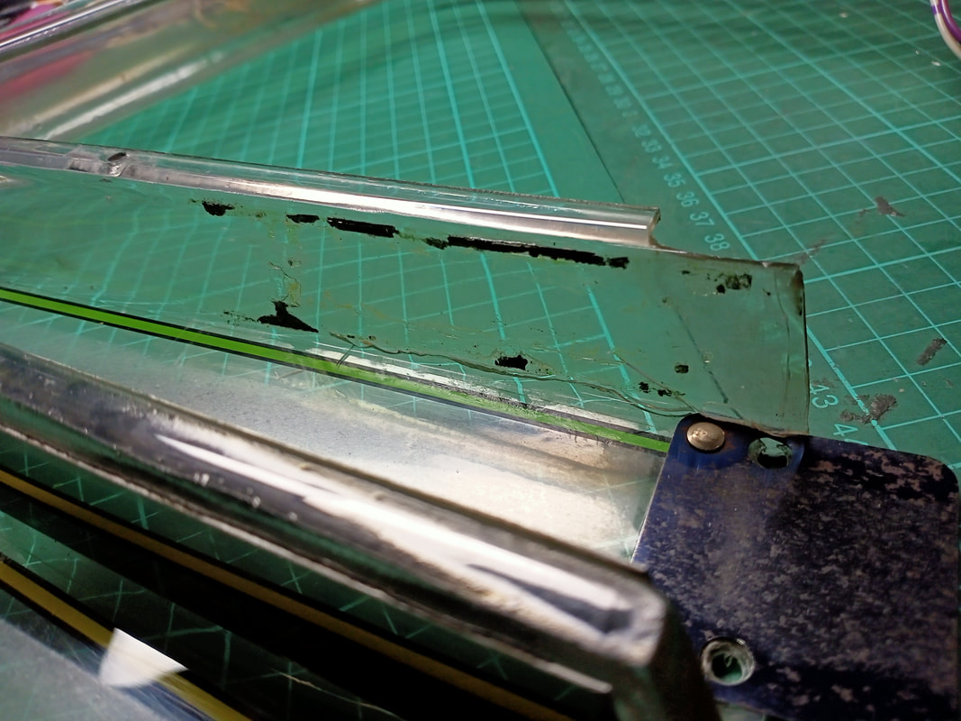
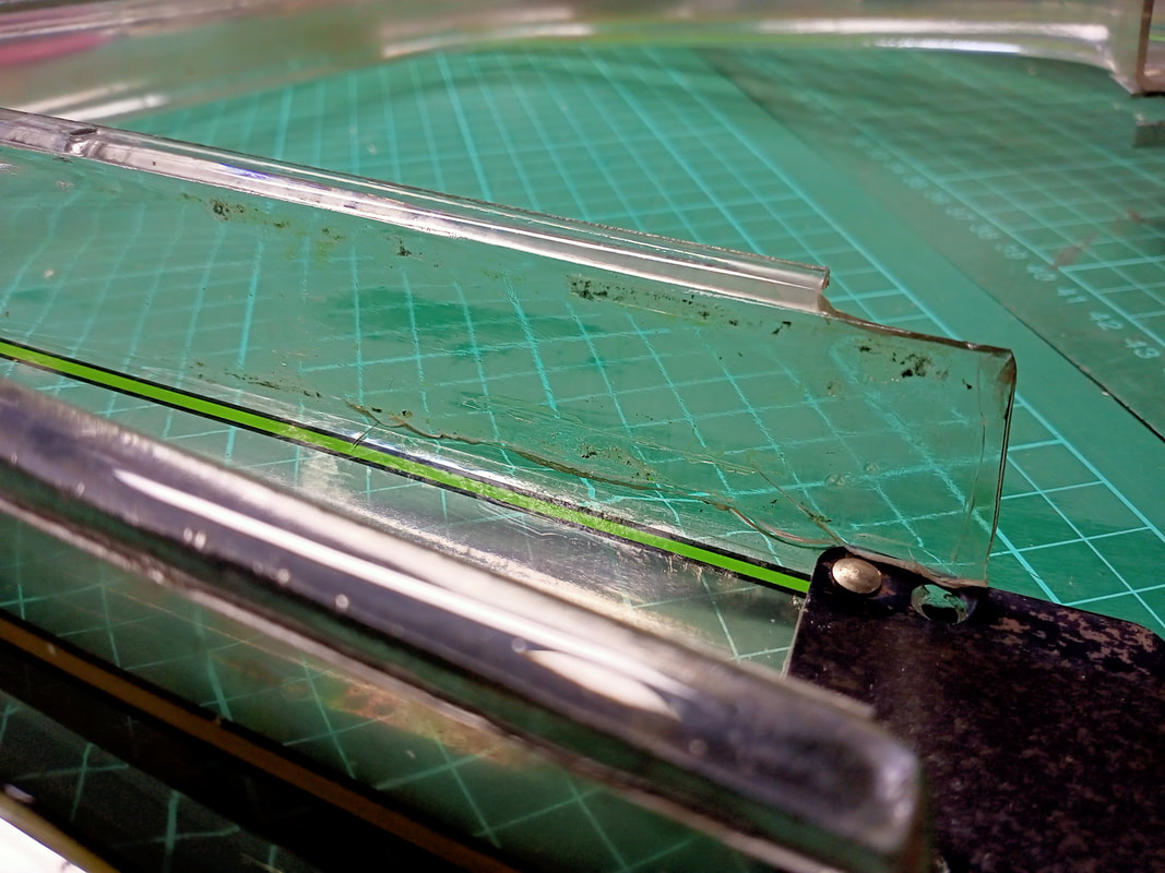
The first step was to clean the ramp as there was a lot of dry residue on the exposed side where a metal ramp protector was once attached. This stuff was dry and hard, and I had to use a scalpel to get most of it off as no amount of scrubbing with a cloth was going to do anything.
Next up was performing the repairs to the ramp plastic. I decided to use Bondic for this purpose, a UV-curable plastic compound which I've used with good success before. Bondic is good for these repairs as it can be built up with successive layers to produce a thicker repair, essentially replacing any missing plastic. Cure each layer with a UV torch for a few seconds. I put a couple of layers on both the left and right sides of the ramp, and the final bond appeared to be quite strong.
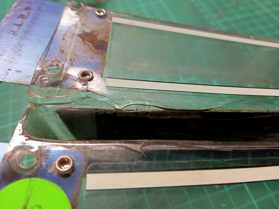
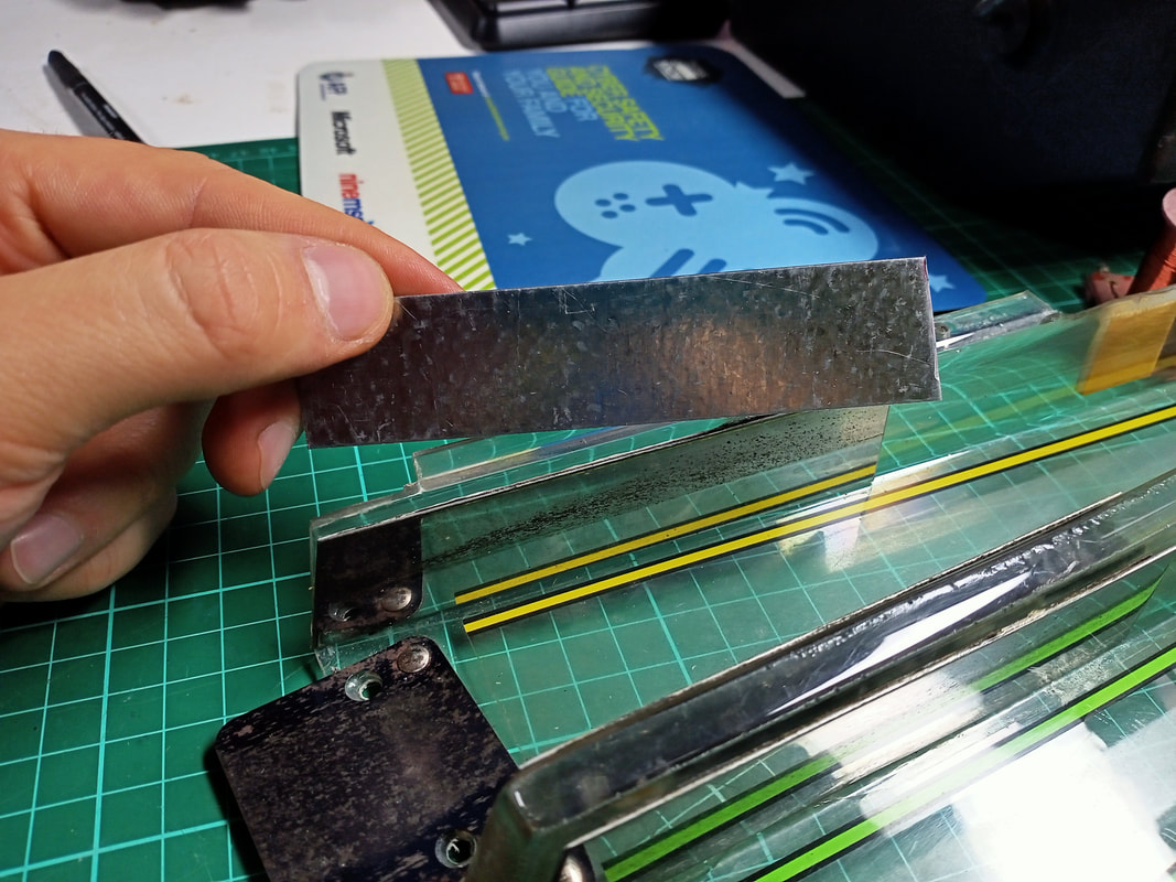
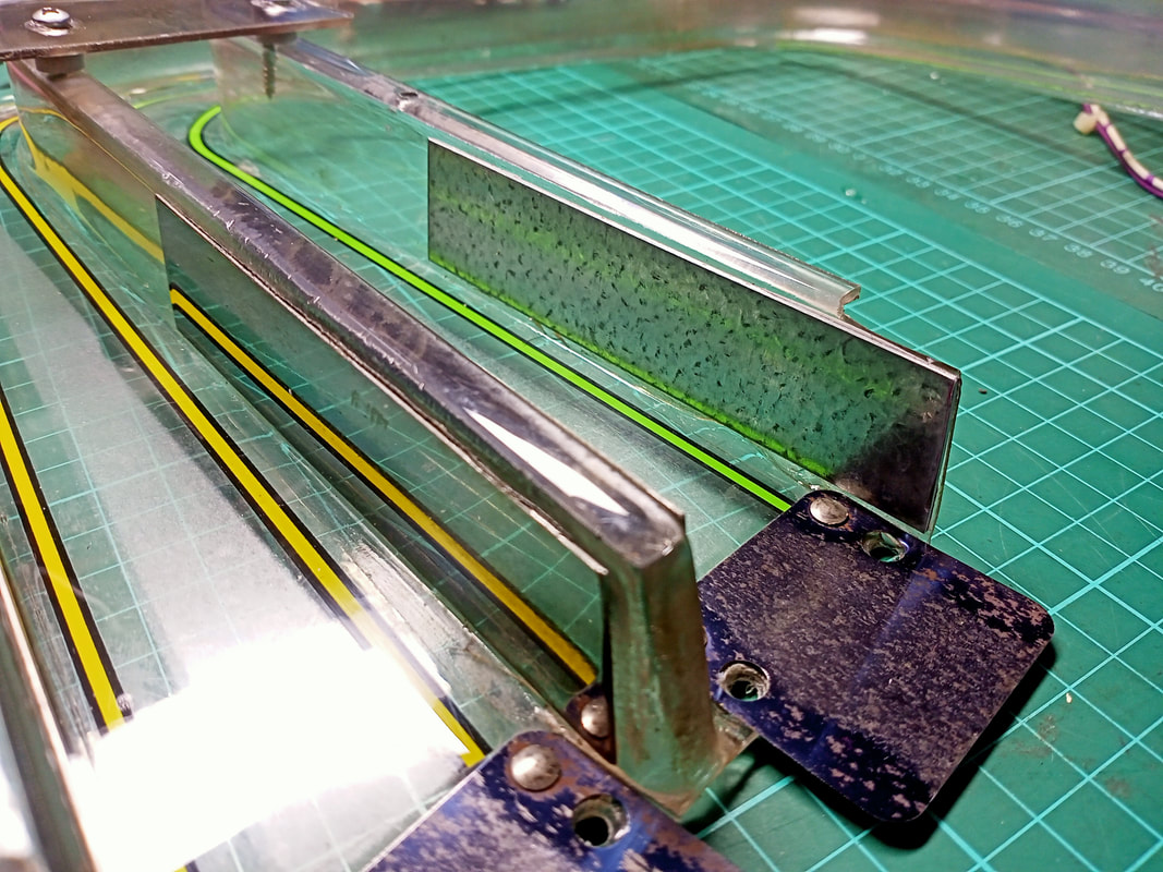
The next job was to replace the ramp protector which was missing from this part of the ramp. The part number associated with these "side guard rails" is 535-5795-00, however they are not available to purchase anywhere. Interestingly, the same part number is listed in the Checkpoint (Data East, 1991) and Simpsons (Data East, 1990) game manuals as belonging to "Ball Shooter Rail Guard". Apparently this same piece of metal was used to protect the shooter lane before being used as a ramp protector in Teenage Mutant Ninja Turtles. The protectors themselves are simply short strips of metal which line the walls of the ramp. To be honest, it is difficult to see how they protect from damage, as they are not anchored to any posts or other structural supports. Therefore, any ball hits to the protectors will still transfer all of their energy to the ramp plastic. However, they do help distribute the energy across a greater surface area, so they are a little effective from that standpoint. I used a strip of galvanised steel which was just the right size (about 2 cm high). I simply cut this to the appropriate length (about 10 cm) with an angle grinder, including a small angle at the front edge to match the shape of the plastic at the ramp entrance. Then I ran the edges along the bench grinder wheel to remove any swarf and sharp edges. I attached the protector to the ramp with double-sided tape which works well on this section of ramp as it is quite straight.
All done! I reinstalled the ramp into the game and continued fixing other issues. Some time later I was playing some test games to make sure other repairs were successful. I made a shot from the right flipper to the purple targets on the left of the playfield. The ball hit the targets, then deflected and hit the new ramp protector with full force. Crack! The plastic cracked again in exactly the same spot on the right side of the ramp. The Bondic had failed, and the ramp protector also fell off the ramp wall. I decided to try a different repair method, and after cleaning the dried Bondic compound off the ramp and out of the crack as best I could, I used Selleys 5-Minute Araldite to repair the crack. It's worth noting here that the crack on the left side of the ramp was still intact; only the crack on the right side had been breached again. After the second repair had cured (16 hours), I once again reinstalled the ramp and played a number of test games. The ramp actually took a couple of indirect ball hits and appeared to hold up OK. However, a bad bounce off one of the posts at the entrance to the ramp sent the ball straight into the side of the ramp (just like in the video I posted at the start of this section). Again, the ramp cracked in the same place. At this point there was not much else I could do. The damage to the ramp in this game is simply a result of bad playfield design. Balls should never be able to strike the sides of a plastic ramp so directly as they do in Turtles and the ramp protectors don't offer any significant protection in this situation. Pinsider durgee7 posted some pictures of custom-made protectors of a different design. These ones are anchored to the playfield posts at the ramp entrance, and would actually absorb a lot of the energy from ball strikes instead of transferring it to the ramp. These seem like the best bet for ramp protection. The other option would be to support the ramp with extra plastic or metal framing, potentially around the sides and underside. However, this would require a lot of additional work and would be ugly as sin. Thankfully the ramp still works as intended even when cracked, so I decided to leave it as-is until a reproduction ramp becomes available (fingers crossed!). 2021 update: Reproduction ramps are finally here! Jody at Ramp-O-Matic has finally reproduced the Teenage Mutant Ninja Turtles main ramp! It is available in clear or green and is available locally from RTBB (clear and green). Decals are also available from RTBB (skill shot decal and line decals). The next time I service this game, a new ramp is going to be my first suggestion for the owner. Not only will it be thicker plastic, but I will also fabricate some different protectors to better guard the ramp sides. Miscellaneous issues and fixes
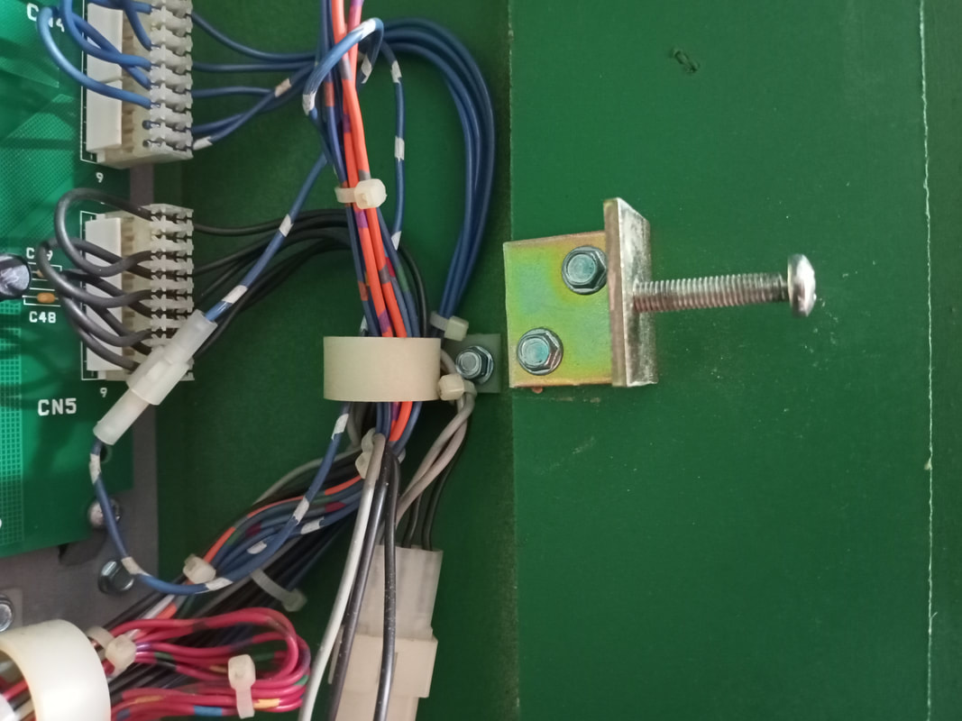
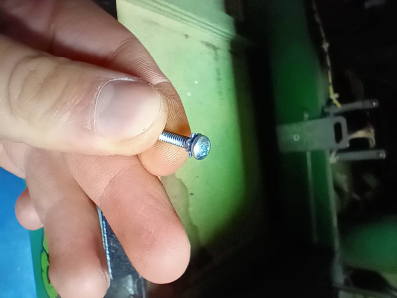
Most people don't bother with bolting the backbox into place because of the locking system that Data East used, which admittedly is much sturdier than the flimsy latch that Williams and Gottlieb used. However, backbox bolts are an important safety feature and should always be used. This game was missing its bolts, so standard black leg bolts were substituted instead (PSPA, Mr Pinball, RTBB).
Standard leg bolts installed as backbox bolts.
There was an issue with the outhole switch not always registering the ball once it drained. While inspecting the switch I found it to be loose on its mounting bracket. Turns out, it was missing a screw. Luckily the screw was found in the coin box directly below the switch. Easy fix!
The decals in the backbox on Data East games always seem to fall off. The adhesive on them dries up and they fall into the cabinet, often to be thrown out later. I like to have the original decals, if available, so I reattach them to where they were originally mounted and stick them on with tape (seems to last better than standard glues).
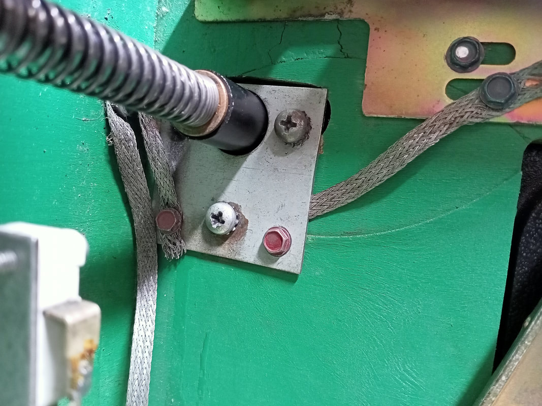
While repairing the shooter rod assembly, the ground braid attached to the shooter rod bracket broke in half. The braid needs to attach to the shooter rod bracket in case it ever comes into contact with solenoid voltage (unlikely, but an important safety consideration). The braid was simply cut neatly, reattached on the left side with a wood screw, and tucked under the bracket on the right side (as it was not quite long enough to reach the screw). Resistance from one end of the braid, across the shooter rod assembly, and out the other side was less than 1 ohm, which is perfectly acceptable. New lengths of braid can be used to replace old ones, too (PSPA, Mr Pinball, RTBB).
The left slingshot wasn't working during a game, and wouldn't activate during coil test, either. The slingshot switches both registered as they should. A quick check under the playfield showed that a wire had broken off the slingshot coil lug. Soldered back on, and back in business. The slingshot switches were also fairly mangled, so I took some time to straighten them out and gap them appropriately.
One of the wires on connector CN7 on the playfield power board was suspicious to me. The yellow-purple wire had indentations in it which suggested it should have been attached to one of the terminals in the housing. According to the manual (page 45), this is correct. the yellow-purple wire should be in pins 8 and 9 of CN7, which supplies 50 volts to the 'A' side coils. I punched the wire back into the terminal at pin 9 of the connector.
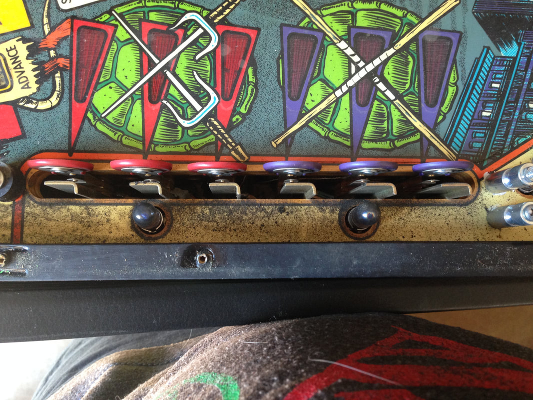
Both flipper bats were cracked! This game must have had a hell of a lot of play before I got a hold of it! New flipper bats were installed (RTBB, PSPA, Austral). I went for yellow flipper bats to match some of the playfield accents. I think this works better than white.
New yellow flipper bats installed.
The balls were left in the tumbler for a day or so to give them a nice polish, and were then finished off on the rag buffing wheel for a minute or so to really shine them up. Don't forget the captive ball! 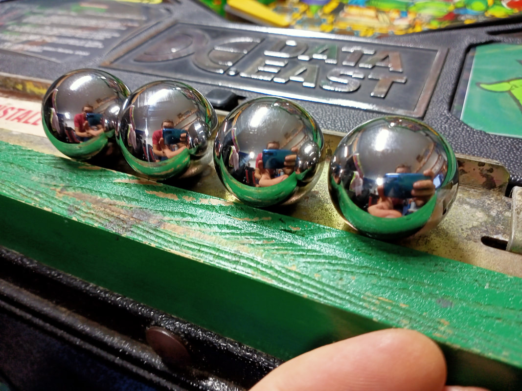
Freshly polished pinballs.
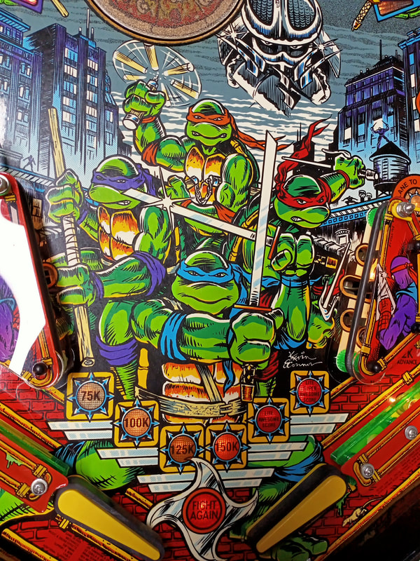
On thing which I did not make any attempts to repair on this occasion was the damaged playfield artwork. The Mylar film had lifted in several spots, particularly around the ramp entrances, and had allowed dirt and debris under it. This resulted in the Mylar lifting, taking some of the playfield artwork with it. Removing the Mylar would have made it look much cleaner, but it would have resulted in patches of missing playfield artwork, too. Data East games of this era (1990-1992) all seem to have issues with playfield paint, as whatever process they used to seal in the artwork was not very effective. Full artwork repair was beyond the scope of this repair, however it is interesting to note that the areas of damaged artwork shown here are common to many Turtles machines.
There was also a problem whereby the trough would not register the last ball when it had been sent to the trough from the outhole. This was not an issue with the outhole switch, as this had been tested and was working. This turned out to be a problem with the trough switch assembly under the playfield, to which all the trough switches are mounted. The leftmost switch would not register reliably when the ball was sent into the trough. This assembly is attached via two slotted screw holes, which allow the assembly to be slid back and forth. These screws just needed to be loosened, so the assembly could be pushed rightwards a little. This allowed the leftmost switch to make more consistent contact when the ball was sitting in the trough and fixed the issue.
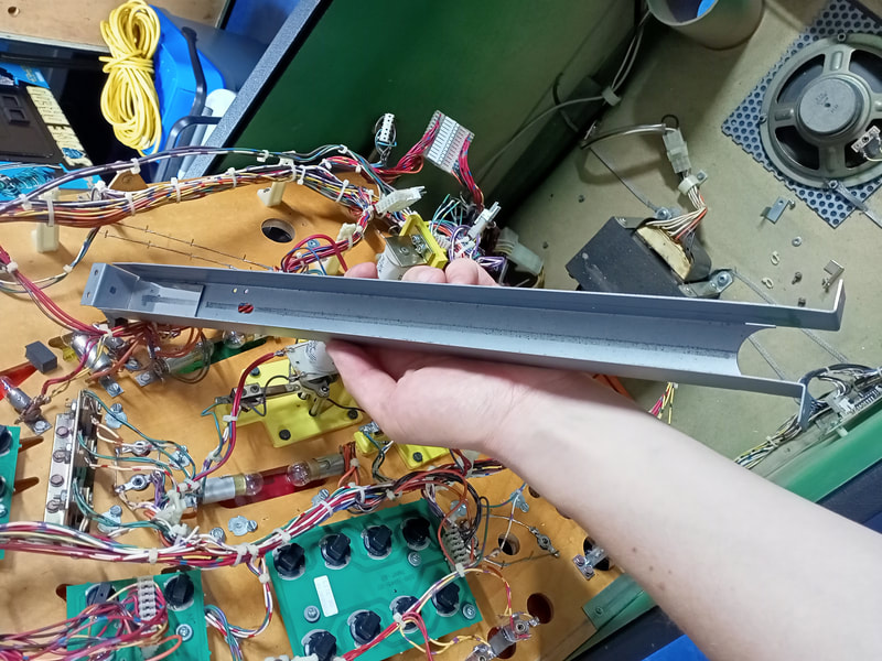
Lockdown bar repainting
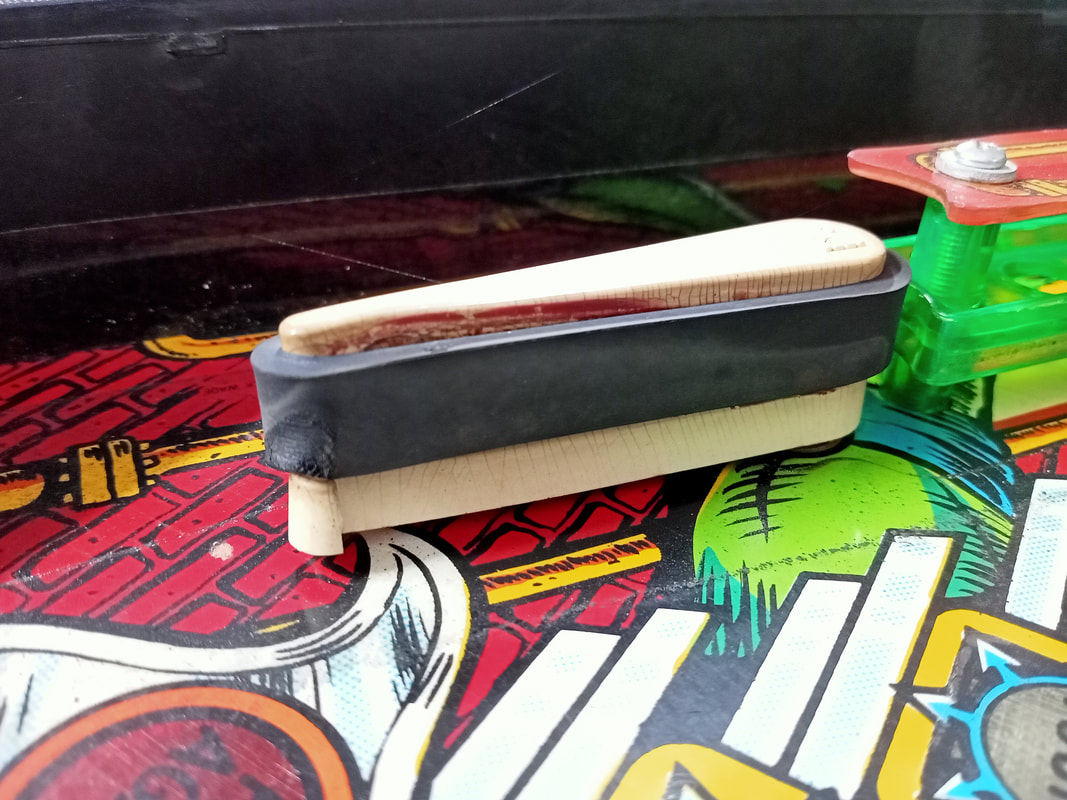
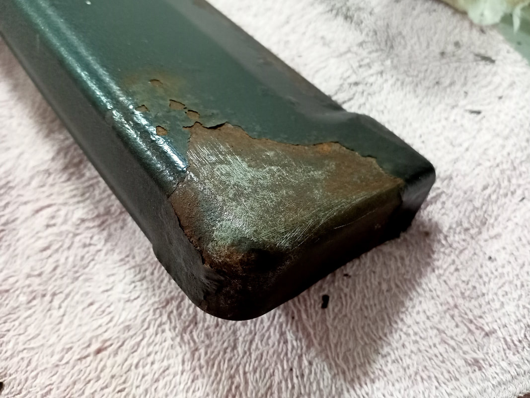
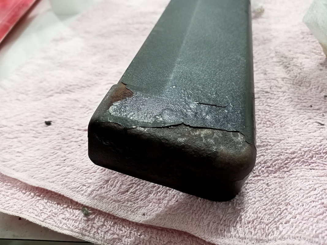
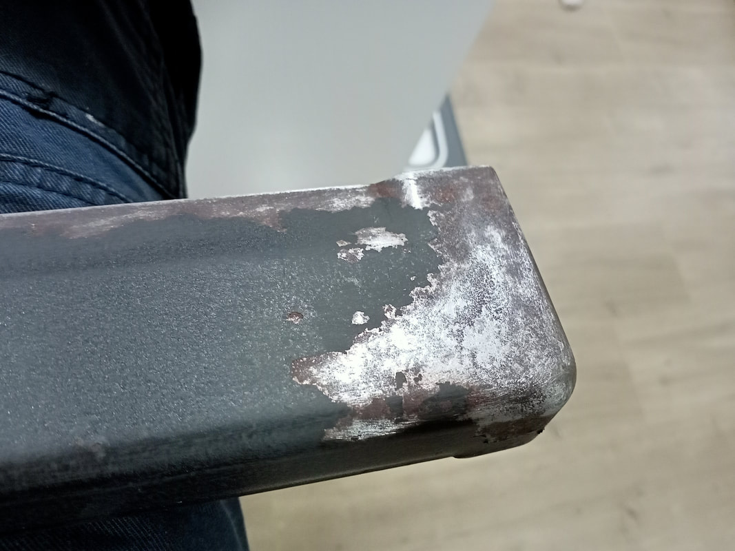
The lockdown bar was in poor shape. Much of the paint had peeled from the corners of the bar where the palms of the hands are placed, and rust had started to set in. I decided to repaint the lockdown bar to make it look a little nicer, and protect the rest of the bar from rusting out. The first step was to strip the bar of any loose paint, rust, and other debris. The tools of choice here were scalpels, razorblades and coarse grit sandpaper. Even in areas in the centre of the lockdown bar, paint had begun to bubble up due to rust intrusion, so these patches were also scraped back to expose the bear metal underneath.
Once the paint had been scraped off and the bare metal was exposed, it was sanded as much as possible to remove large patches of rust. Rough areas of remaining paint were also sanded to ensure there were no flaps or tags which would easily peel off later on.
Don't forget the rear of the lockdown bar, too. A lot of the paint had flaked off the inner corners here, too. Plus, the old strip foam across the bar has to be removed. The adhesive is old and tacky, and difficult to remove. Liberal application of Goof Off (Bunnings) made this a lot easier. 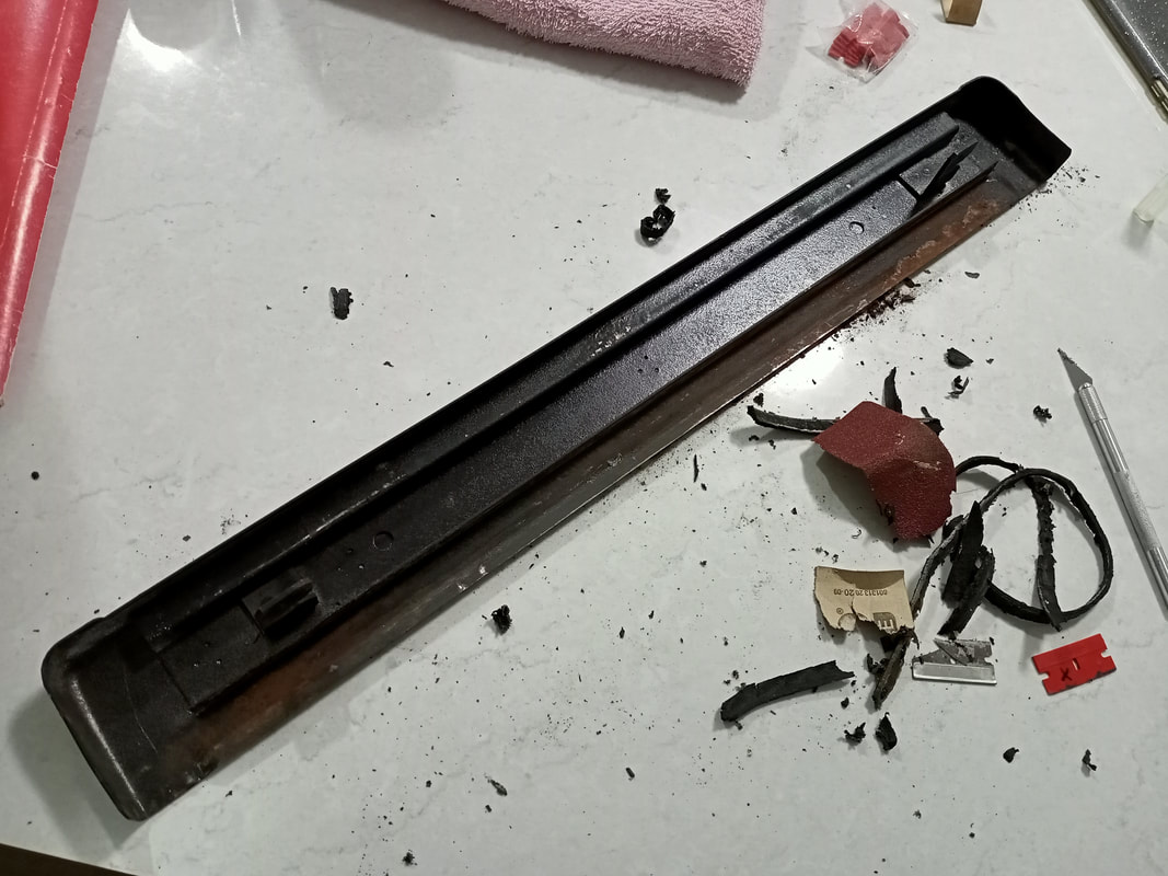
Removing the crusty old foam seal on the underside of the lockdown bar.
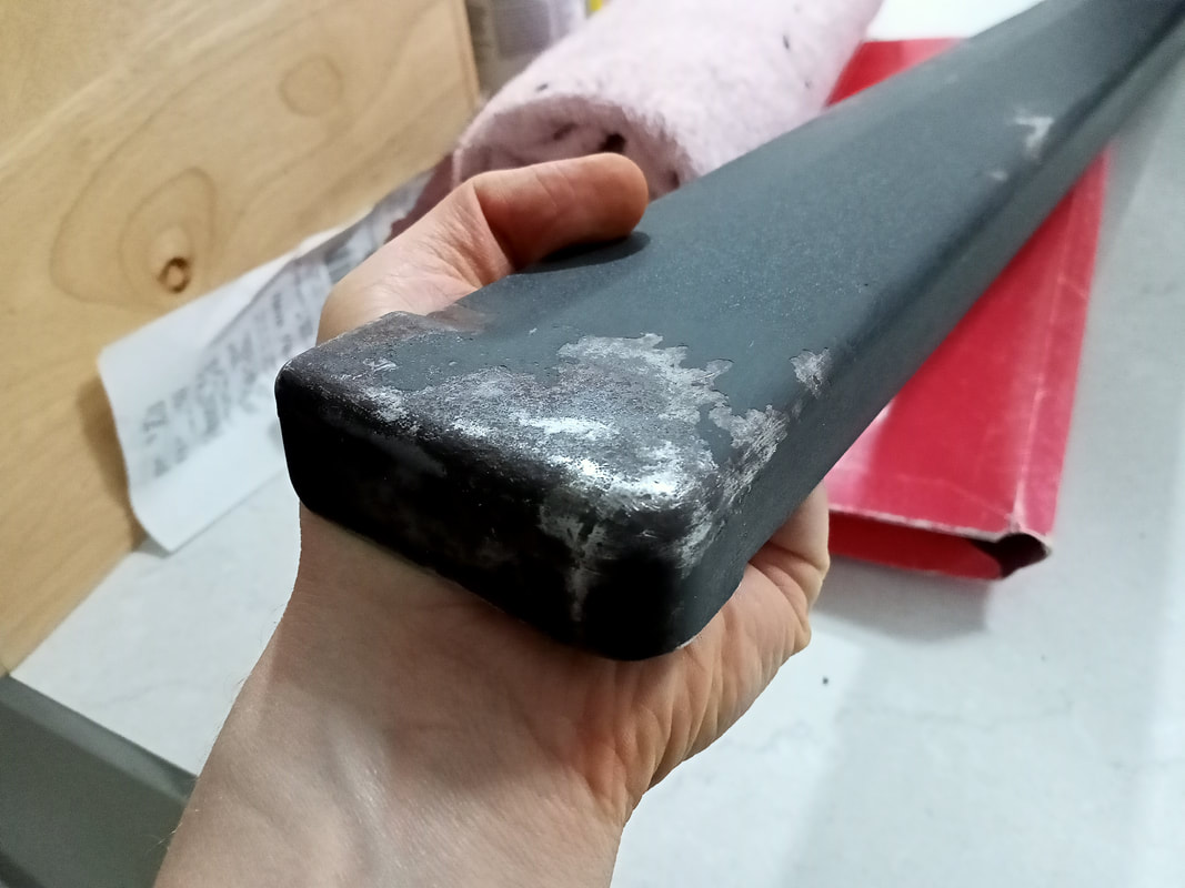
At this point the lockdown bar was stripped of a fair bit of paint and the major rust spots had been sanded off. It was time to clean the bar and prepare it for priming. The primer I used was Fiddly Bits Grey Primer (Bunnings). I coated the entire bar, front and back. There's no sense in doing only the bad bits, as this will give an inconsistent look. Once primed with two full layers, it was left to dry for a day. Then, the primer was followed up with a coat of black paint. For this I used Dulux Metalshield Epoxy Enamel (Bunnings). Two full coats of this were applied. To finish, a clear coat was applied - Dulux duramax semi gloss (Bunnings). I did four coats of the clear coat as this would provide a good layer of protection for the underlying black paint. I applied it a little more heavily around the corners of the bar, where the palms usually sit. This is where most of the wear occurs, so a thicker layer of clear here will protect it a little longer. Of course, a new foam seal was also installed (Bunnings).
New foam seal installed under lockdown bar.
The end result is not as smooth as even the original paint as you can still see some of the pits and dips where the original paint was removed, but it is certainly miles better than the rusty bar we started with! It's a nice way to finish off the restoration, as seeing a crappy, tired lockdown bar can detract from the look of an otherwise nice machine. This one now looks the part! Reassembly Here's a pro tip when reassembling the posts and plastics at the rear of the playfield. The wire gate above the pop bumpers attaches to two posts. The upper post is a metal screw, which screws into a T-nut under the playfield. I had a lot of difficulty trying to screw the wire gate into this post, as the wire gate is the last item to go on after the post, rubber, and plastic is installed. You need to keep the post in place (while it is under the strain of two rubber rings pulling on it) as you try to screw the post through the wire gate and plastic. It's a pain in the ass to do. Instead, make your life easier by getting rid of the original screw, and replacing it with a standard stud post with thread at the top (part no. 530-5012-02, RTBB, PSPA, Austral). These screws are used elsewhere on the playfield but for some reason one was not used here, where it would make life much, much easier. This post allows you to tighten the post and install the rubber rings, then install the plastic and wire gate over the top without having to deal with the rings pulling the post away. Install a plastic acorn nut (PSPA) over the top and it looks just like an original post! 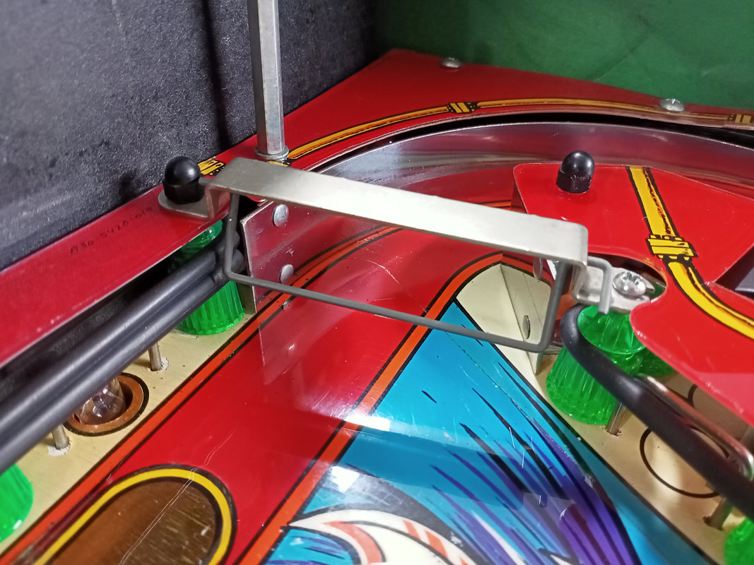 The wire gate screw on the left has been replaced with a post. Makes installation of the rubber rings and wire gate much easier! The wire gate screw on the left has been replaced with a post. Makes installation of the rubber rings and wire gate much easier! Also, don't forget to leave the upper left plastic (the one which Raphael sits in) a little loose before you install the ramp. You need to weave the lamp connector through the two clear pieces of plastic before you can punch it through the hole in the playfield, and this is much easier when one of the plastics is loose. 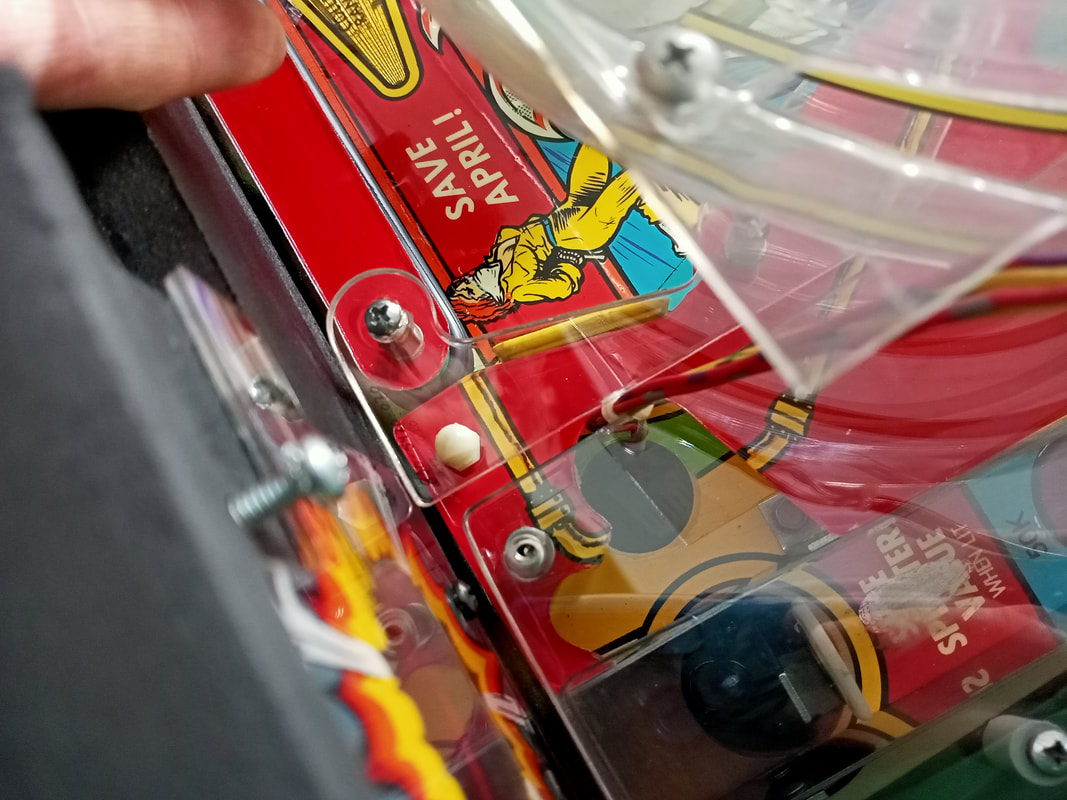 The ramp lamp connector is routed past two clear plastics; leave one loose to make pushing it through easier. In terms of new parts and replacements, new lamps replaced broken ones, with the majority of broken bulbs being flashers under the playfield rather than controlled lamps or general illumination. I opted to stick with incandescent globes. The foam backings had perished from the standup target brackets, so these were replaced with small strips of adhesive weather strip. Other than that, the playfield, plastics and ramps were given a good clean before being put back together. One ramp protector for the left ramp was found in the coin box and was reattached to the ramp with double-sided tape (this was a different protector to the one which I fabricated). Oh, and new instruction cards, too! The best collection of Ninja Turtles instruction cards is on this Pinside post by Coindropper. There are a few here to choose from, and I went for the set below. Simply print to the correct size (Data East instruction cards are 76 x 140mm).
After seeing the cards on the game apron, I wasn't a big fan of how the turtles were depicted. So, I made up my own simple card with just the Turtles logo on it. Nice and simple! Feel free to download the original file below for your own use.
Simple instruction card I made using only the TMNT logo. Conclusion Working on Teenage Mutant Ninja Turtles was a good introduction to early Data East dot matrix display games. Some of the issues on this game were troublesome but none were insurmountable, and after all was said and done, the game finished up playing very well and looking good. Originally, the flippers were so weak you could barely make it up the ramps, but after a rebuild, they were as strong as ever. The game is much more fun to play when you can hit all of the shots! Data East flippers of this era were unnecessarily strong in my opinion, and it's not unusual to see some air balls and crazy deflections off a strong flipper hit. The ramp shots are fun to hit (when not breaking the ramp), and it's fun to see how many ramp combos you can hit in a row. The sewer shot is advertised as the first ever subway shot in pinball on the game flyer, which is a pretty cool thing when you think about how ubiquitous subways became on pinball machines in the early 1990s. That said, not all Data East innovations were a good idea. The Turboboost ball launch kicker is a horribly designed mechanism and it is no surprise it caused so many issues on other games. It was not fun to work on, but it is working reliably now. It's no surprise they stopped using this mechanism after Teenage Mutant Ninja Turtles. All in all, the customer was very happy with the end result and was eager to get the game home and finally give it a play after so many years. truth be told, he only wanted a simple shop job, but I ended up doing quite a bit more for the sake of a nice playing, and reliable game. This restoration took about 30 hours in total, but I was happy to take a hit on that just to say that I got it going as best I could. Cowabunga!
2 Comments
robert
10/10/2023 03:18:06 am
I really enjoyed reading your restoration on TMNT. I recently picked up a TMNT and finding several issues. First thing I noticed was there is no fuse holder in F3 on the power board, is that normal? There seems to be some brown on CN8 and the base of the wires on CN9. I am considering replacing but read one of your restoration posts on where you like to stick to the original if possible but I am wondering if I should just consider a power board replacement.
Hi Robert! Leave a Reply. |
About
Here you will find logs of our pinball and arcade machine restorations, repairs, discussion about general pinball and arcade topics, as well as recounts of our random pinball adventures.
Check back regularly for updates! Blog updates
Archives
May 2024
Categories
All
Donate

Running this website is a hobby for me (just like pinball!). I like being able to show off my restoration work so everyone can learn from it and potentially fix their own machines. If you enjoy reading the site's content or it has been helpful to you, please consider donating to offset some of the website's operating costs. |
||||||||||||||||||||||||||||||||||||||||||||||||||||||||||||||||||||||||||||


 RSS Feed