|
It seems to be the season for battery corrosion on pinball circuit boards. Over the last few months I have repaired several Williams WPC-era MPU (CPU) boards which have suffered various levels of battery corrosion. Original WPC CPU boards are now at least 33 years old, which is an eternity when it comes to electronics. By this point, a randomly-selected CPU board will have had many issues during its working life which would have necessitated bench-level repair. However, for the most part, these repairs would have consisted of replacement of a couple of defective components; a relatively non-invasive procedure. Battery corrosion repair is a different beast, and is more akin to amputation followed by transplantation. Unfortunately for the boards featured in this blog post, the corrosion was discovered too late, so some extensive repairs had to be carried out. This post deals with three levels of battery corrosion: minor, moderate, and major, and the actions undertaken to get the games back into working condition. There is some great information available regarding how to tackle these kinds of repairs, such as the Alkaline Corrosion Abatement section on Pinwiki, and TerryB's Guide to Repairing Alkaline Battery Damage. I used tips from both guides to carry out these repairs. Background and a little chemistry lesson
Few issues, however, are as "deadly" to circuit boards as corrosion from leaking electrolytic fluid. Battery leakage typically manifests as physical deformation of the battery cell casing (i.e. bulging or splitting), usually accompanied by the presence of a white, green, or sometimes blue precipitate material around the battery terminals. This material is potassium hydroxide, the electrolytic fluid within an alkaline battery cell, which absorbs carbon dioxide from the air to form potassium carbonate, as in the chemical equation below (I knew my chemistry studies would finally come in handy after uni!).
That's enough with the chemistry lesson. Battery corrosion is a typical cause of switch problems, and the inability of a machine to retain its high scores and settings. The circuitry that controls switch functions in WPC games is located adjacent the battery holder on the CPU board, and the batteries themselves are responsible for game memory including high scores and settings. Even a small amount of battery corrosion can be indicative of a much larger issue hiding behind components and between component legs. The key here is to act quickly before the corrosion gains a foothold and becomes more difficult to remove. This should serve as a reminder to everyone to check their CPU boards for damage. For those that are still installing batteries directly onto their CPU boards, take this opportunity to set up a regular battery replacement schedule, or install a battery replacement option. Minor corrosion
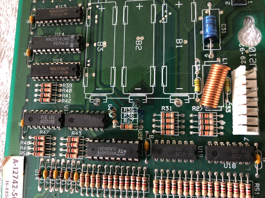
The minor corrosion patient was a Black Rose (Bally, 1992). This game exhibited minor intermittent switch registration issues, whereby some switches would operate only sporadically. Once I opened the backbox to look at the boards, the problem became clear - corrosion on the MPU board. The corrosion was not significant, so I brought the board back to the workshop to take preventative action. I removed the batteries, the battery holder, and a few resistors underneath the battery holder (R35-37). I noted some green electrolyte on some of the integrated circuits as well (U16, U20). Some of the resistors on the right were also looking a little dodgy, with green particles on their legs.
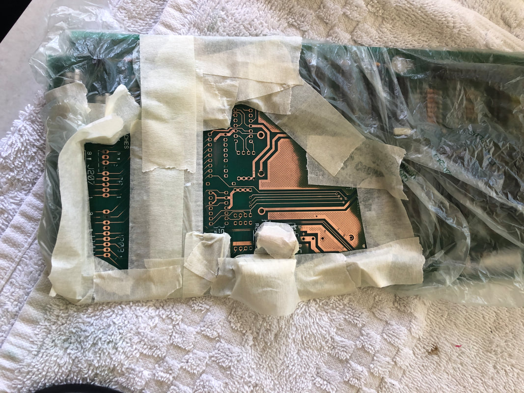
The resistors and capacitors in the rows below U20 all seemed fine and I could not find any trace of corrosion on these components or in the board traces connected to them. However, near the bottom of the board, there were some issues. Connector header pins at J206 and J208 had corrosion on them. This was from the electrolyte leaking from the battery holder and dripping onto the connectors underneath. J206 and J208 are right in the firing line for this and I could see corrosion on the header pins themselves, as well as on the board traces underneath. The corrosion was advancing upwards towards the resistors and capacitors above. So, this area had to be dealt with, too. Unfortunately, I forgot to take a good photo of it. So this board needed repairs in two distinct areas, with some good components in between the two areas which were completely unaffected. I started with removal of components followed by vigorous sanding of the affected areas with 120-240 grit sandpaper to remove all corrosion, followed by a rinse with vinegar (Bunnings) to neutralise the alkali, and then an isopropyl alcohol (Jaycar) rinse to clean. Removal of the resistors and battery pack went smoothly. However, as is sometimes the case when traces and through holes are damaged by corrosion, some of the traces around the connector header pins at the bottom of the board were destroyed. This could have occurred as a result of the corrosion, as a result of pin removal, or both. Traces on CPU board header pins are quite delicate and they require a fair bit of heat to remove, so sometimes they are damaged. A couple of through holes were pulled, and a couple of traces were otherwise broken, mainly on J206. These were repaired with jumper wires on the rear of the board. At this point, the board was ready for conformal coating (Jaycar) to prepare it for the new components that would be installed. The unaffected areas of the board were masked off, and a light coat of the coating was deployed across the bare copper traces. Then, it was time for component replacement. As I didn't have to replace many of the capacitors and resistors, this board was quite simple to repopulate. Components used are listed below. Note that a more complete parts list is in the "Major corrosion" repair section further down the page. Unfortunately, I forgot to take a photo of the board after it was fully repopulated. However, you can make my word for it that it looked pretty good! The board was reinstalled into the machine and worked without issue, which is always a good sign after a repair such as this. Minor corrosion repair: success! Moderate corrosion
The moderate corrosion patient was an Addams Family (Bally, 1992) which I actually repaired some time ago. This CPU board presented with only a sporadic issue of some switches not working. When I attended to inspect the game, it was actually fully functioning with no issues. However, intermittent switch issues are potentially an indicator of problems with the switch matrix circuitry, so I took a look at the CPU board just in case.
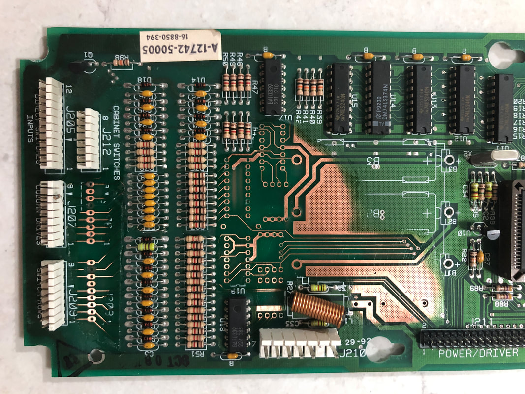
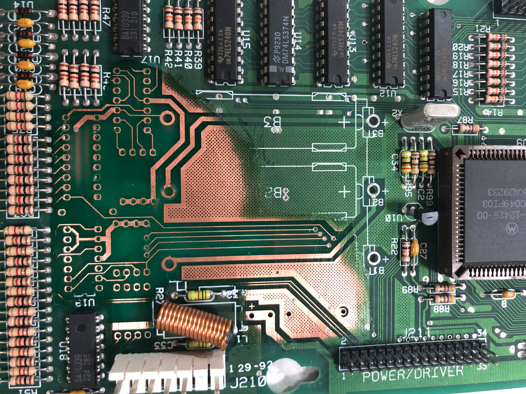
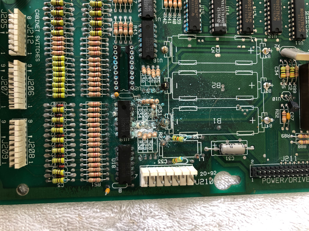
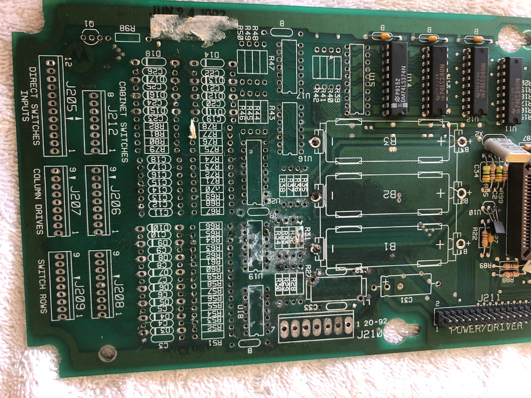
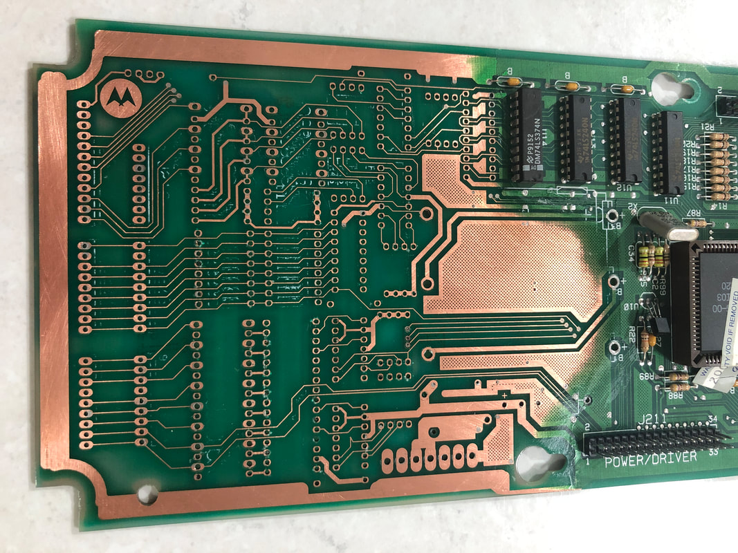
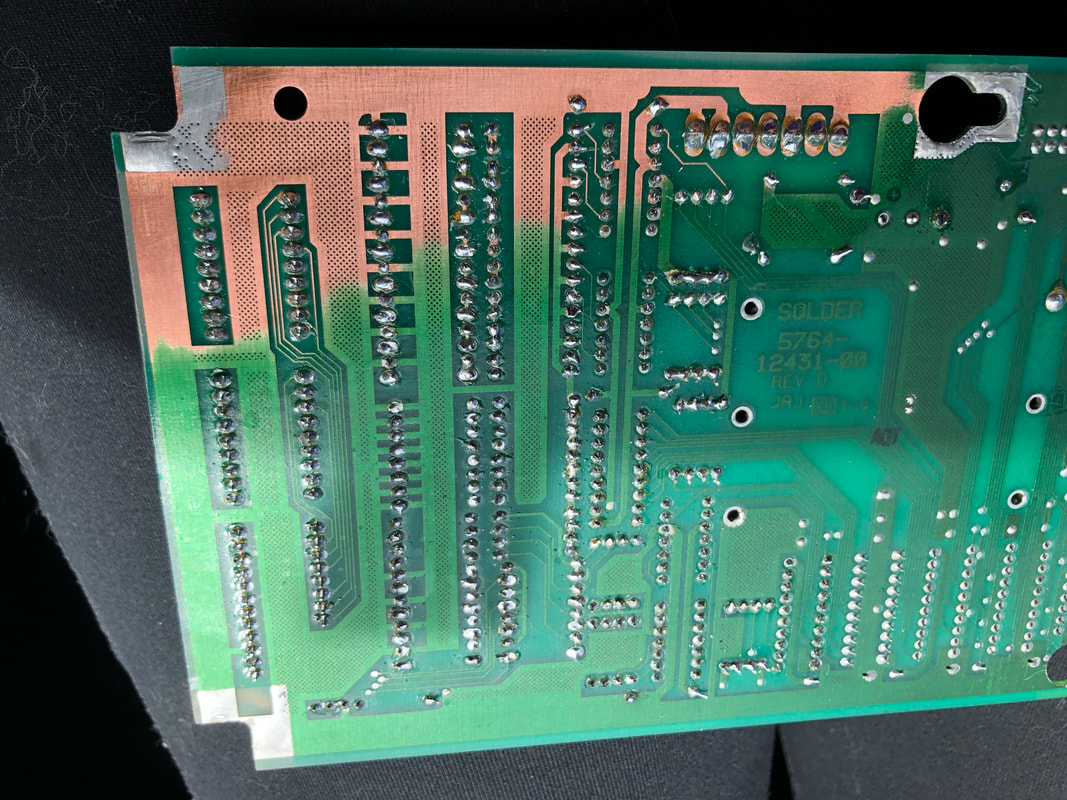
Below the battery holder there was actually a fair amount of corrosion visible, particularly on the bank of four resistors at R31-34. And some of this corrosion had clearly spread to the integrated circuits below and to the resistor banks below those. Once I took a couple of the resistors off, as well as the battery holder, it was easy to see that the corrosion was actually quite advanced, with a lot of it traveling under the solder mask. This was particularly visible where the batteries were mounted, with black marks indicating the spread of electrolytic fluid under the top later of masking. Once I see corrosion at this level, it is usually a matter of search-and-destroy to find all locations where the corrosion has penetrated, then neutralising it. The problem with leaks that have penetrated into the solder mask is it can be very hard to see how far it has spread unless you remove the through-hole mounted components first. My approach is that it is better to be safe than sorry, and to remove ALL potentially affected components. In this case, this refers to all components below the battery holder. As is usually the case, a few of these components were very difficult to remove due to contamination of the solder pads by the battery electrolyte. A lot of extra solder was needed to persuade some of these component leads to give way. Many people would suggest that this level of component removal is a nuclear solution, but I prefer to err on the side of caution. Once all the components were off I could properly evaluate the corrosion. Most of the integrated circuits (U16-U20) were affected. Even U15, which is slightly higher than the others, had some green fuzz on its legs which was indicative of battery alkaline. The resistor bank below the integrated circuits (starting with R51) was also shot. Even the capacitors and diodes below that (starting with C3) showed some evidence of green electrolytic fluid on the component leads. The header pins at the bottom seemed relatively clean, but some minor dark marks behind the solder mask showed that they, too, were affected. In the end removal of all components turned out to be worthwhile, as most of them were affected and needed to be removed anyway. Corrosion is like cancer and needs to be treated with the pinball version of radiotherapy. While it is extreme, it is the only way to be sure it won't return. As the corrosion was beneath a lot of traces on this board, I decided to forgo the neutralisation with acid and proceeded straight to the abrasive removal with sandpaper. In my experience, 120 to 240 grit works well for this and between the two you have a good balance between speed of action and harshness of the abrasive action. This board is one of the few boards I've repaired which also exhibited some dark traces on the rear side, also. So those were also targeted for sanding to be sure none of the corrosion remained. Once the board was sanded back to the copper traces, all of the corrosion appeared to have been removed. However, just to be sure, I followed up with a neutralising step with vinegar (Bunnings). A few passes over the board with this made sure the corrosion was gone from any nook or cranny it may have been hiding in. The board was then rinsed off with isopropyl alcohol (Jaycar) leaving a nice, shiny surface behind. At this point I did some probing with my meter to see if any of the traces or through holes had actually been physically damaged by the corrosion or during component removal. Thankfully not! All traces buzzed out OK, and all through holes remained intact. That's always a bonus when doing this type of repair as Williams CPU boards have quite fine traces which are easily damaged. Now the board was ready to coat with a conformal coating (Jaycar) to protect the copper traces. The coating applied well and looked nice and shiny after application. Time to solder some new components in! Most of the components on the bottom half of the MPU board can be purchased locally. Below are the most frequently occurring parts on the bottom half of the board. I sourced most of these locally from Jaycar, as I didn't have a lot of these on-hand at the time. Note that a more complete parts list is in the "Major corrosion" repair section further down the page.
A couple of component mods can also be done at this point. Obviously, you'll want to replace the original battery cells with a more robust solution. I like using 3-volt lithium button battery cells on Williams MPU boards as they fit in this space and can easily be changed. The inductor at L1 can actually be replaced by a thick length of wire, or you can replace it with an original part (PSPA). Otherwise, be sure to upgrade the capacitor at C31 to a higher voltage rating, as this cap is an important component in the 5 volt processor circuit. Once the new parts were in, the board was reinstalled and everything worked properly again. Moderate corrosion repair: success! Major corrosion
The major corrosion patient was a Terminator 2 (Williams, 1991). According to the owner, this game had been having issues with switches as well as issues keeping high scores and settings for at least a year. That was not a good sign, as corrosion gets worse over time and if it started having issues a year ago, there was high chance that the corrosion was quite advanced even then. God only knows what it would look like now. I took the board out of the backbox and had a look.
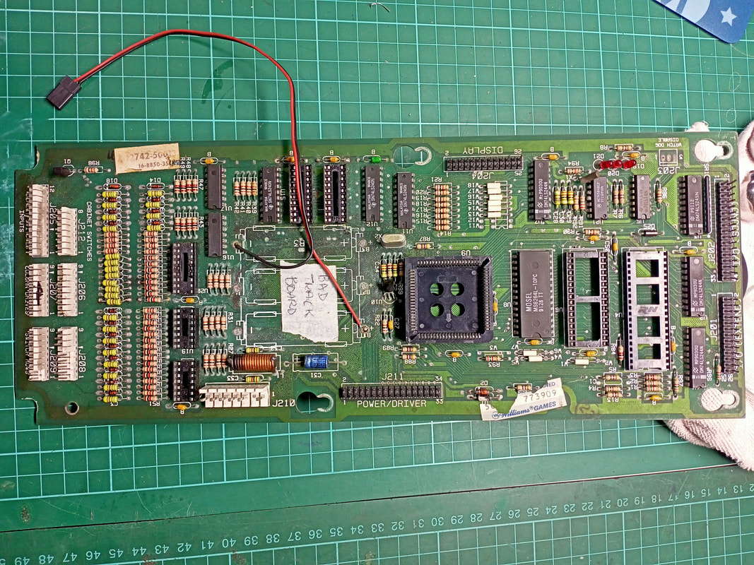
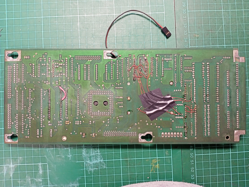
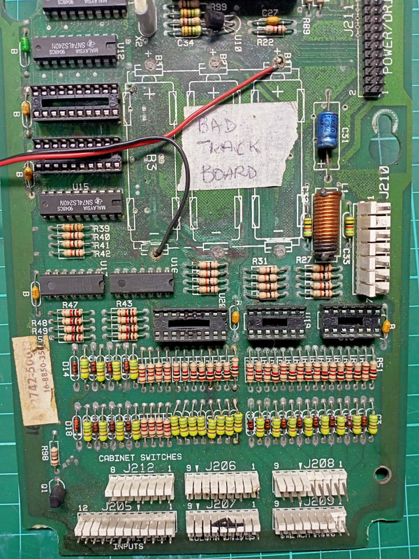
A couple of things popped out at me. First, there was a label on the board which read "bad track board". Already not a good sign. Second, when I flipped the board over, I observed a number of jumper wires connecting components on the bottom half of the board. Somebody had already tried to repair this board by running extra wires to connect components when the traces between them were no longer carrying current. The reason that these traces were starting to fail was obvious. There had been some significant battery leakage on this board in the past, and it had progressed to the point that almost every component on the bottom half of the board was affected, all the way up to the ASIC socket. There were even traces of corrosion further up on the board, with dull solder joints and very faint traces of green material on some component legs. I could see dark spots behind the solder mask everywhere on the board, indicating that the corrosion had found its way into the traces, and had likely destroyed some of them. Tracking down severed traces such as this can be very difficult, and this was likely the reason that so many jumper wires had been run by whoever repaired this board last. Based on this assessment, I decided that this was one of the few cases where replacement of the board would be more economical than repair. Plus, a new board would be much more reliable as there would be no risk of the corrosion eating into new traces which were previously intact. Now, new WPC CPU boards are readily available from a number of suppliers, as several companies have reproduced this board. Some of the ones available locally include:
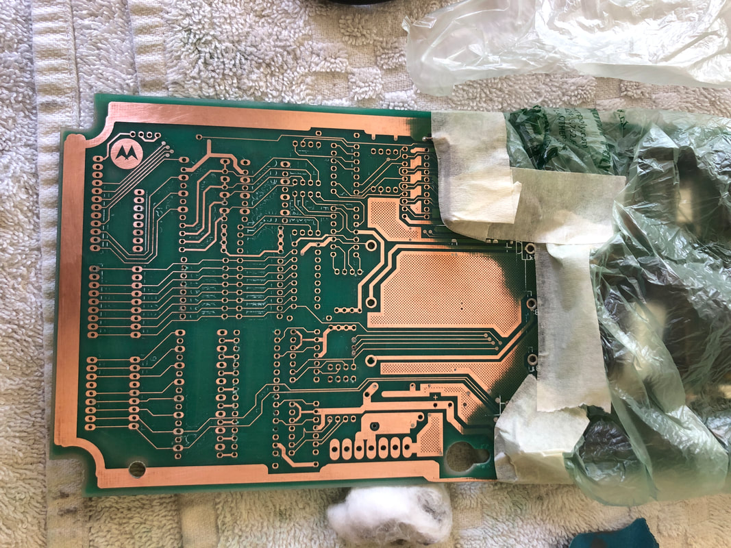
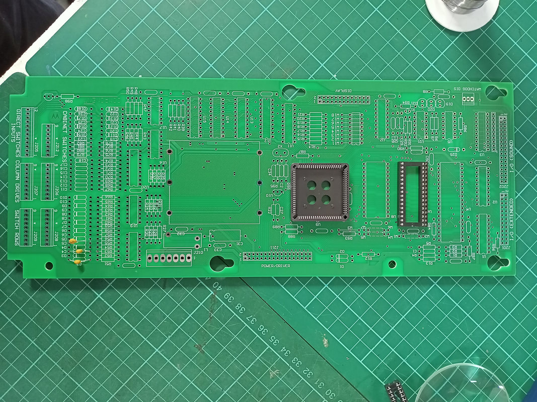
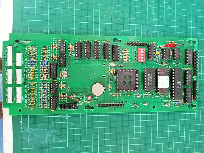
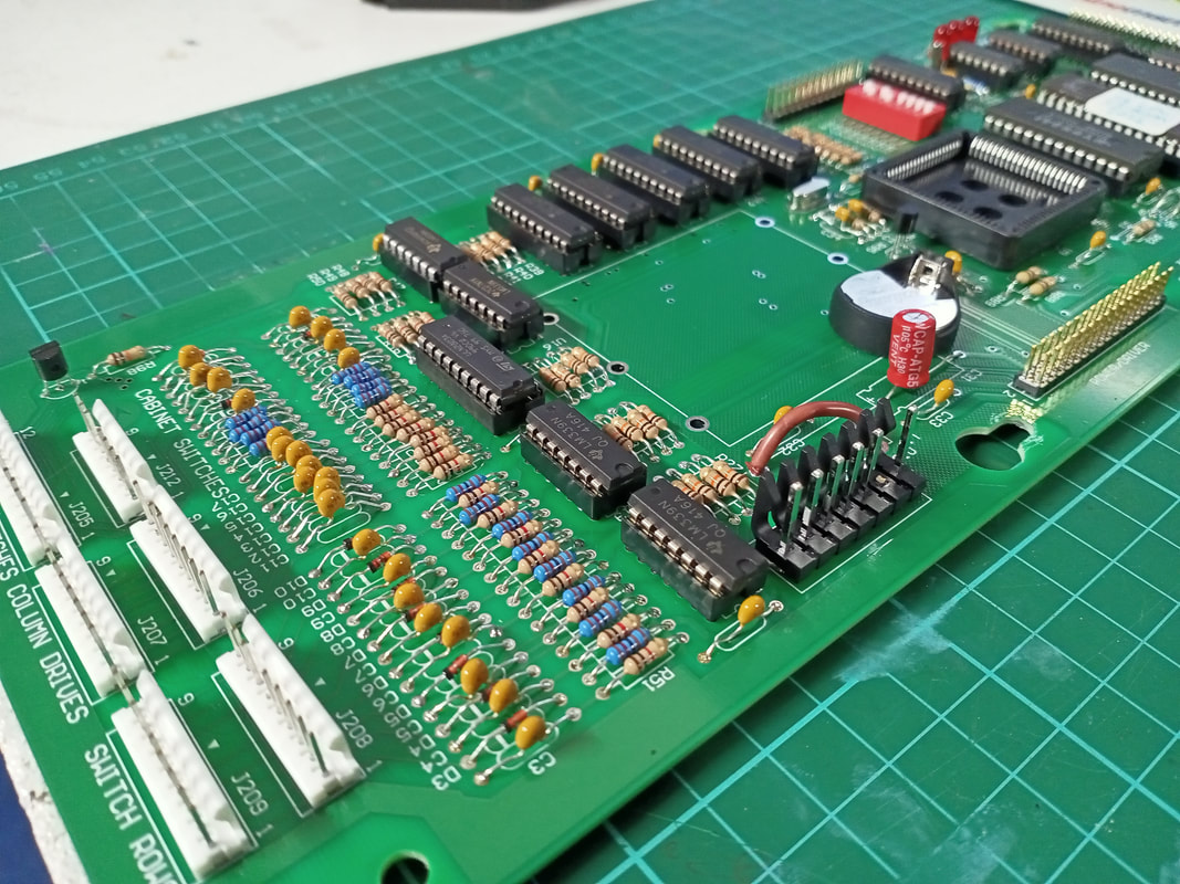
A couple of these boards are available at around the $300 price point, which is quite good considering the number of hours it would take to depopulate, clean, repair, and repopulate the original board. But is there a cheaper way? Yes, there is. You can actually buy bare CPU boards with no components on them (Mr Pinball). If you acquire all of the necessary components, you can populate the board yourself, saving a couple of hundred dollars. Plus, populating a board such as this is a fantastic way to polish your soldering skills and learn more about how the CPU board works. I was up for a weekend project, so I ordered a bare board and got to work. There's nothing quite like a shiny new printed circuit board! Now, a project like this is not for complete newbies. You need a bit of experience with soldering on PCBs before you dive into this one, as there is some relatively fine soldering to do and there are a lot of components. Expect to spend an entire afternoon (several hours) on soldering everything in. You'll also need to transfer the CPU, game ROM, and ASIC chip from your old board. Luckily, these components were still in good condition, so I could reuse them on the new board. If you are building the board from scratch you can order these components separately, but they are expensive.
Those are three of the necessary components. But there are hundreds more on the board; what about those? If you enjoy a bit of punishment, you can sit down with a WPC game manual, flip to the page with the CPU board component list, and simply search for each and every component from an electronic parts retailer. Sounds like fun, right? I started doing this but after 10 minutes I realised there had to be a more efficient way. Pinside user Pin_Guy documented a similar project where he populated a bare MPU board. That forum thread has a lot of useful information for anyone looking to take on this project. The most useful link in that thread was to a spreadsheet containing links to buy all of the necessary parts, complete with costings. Fantastic! The only problem was that this list was based on using Mouser as the primary component supplier. I prefer to use other suppliers, and after some research I found that element14 appeared to stock most of the necessary components in reasonable minimum order quantities and at reasonable costs. So, I edited the spreadsheet and updated it with links to element14 products. This took a lot of work to cross-reference the relevant part numbers, update prices to AUD, and find a couple of additional parts. You can download a copy of the spreadsheet below.
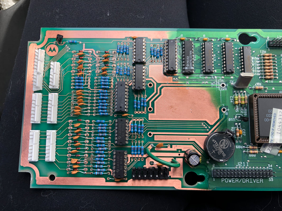
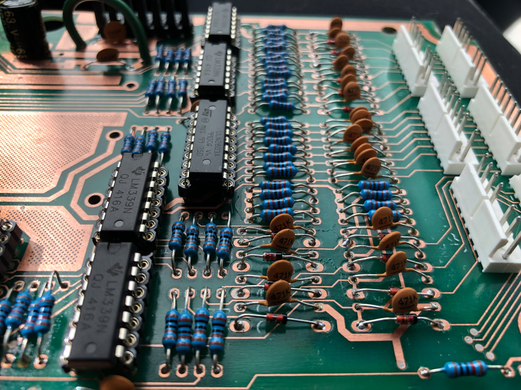
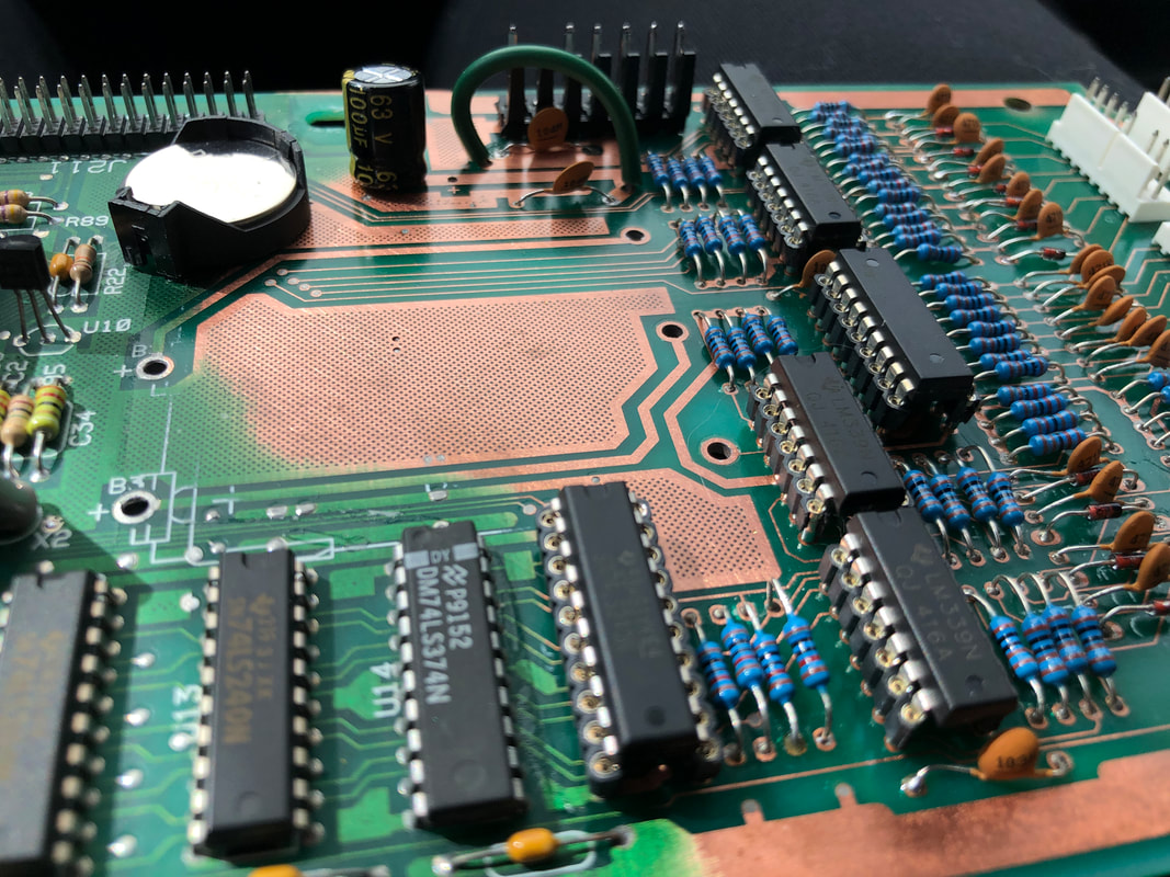
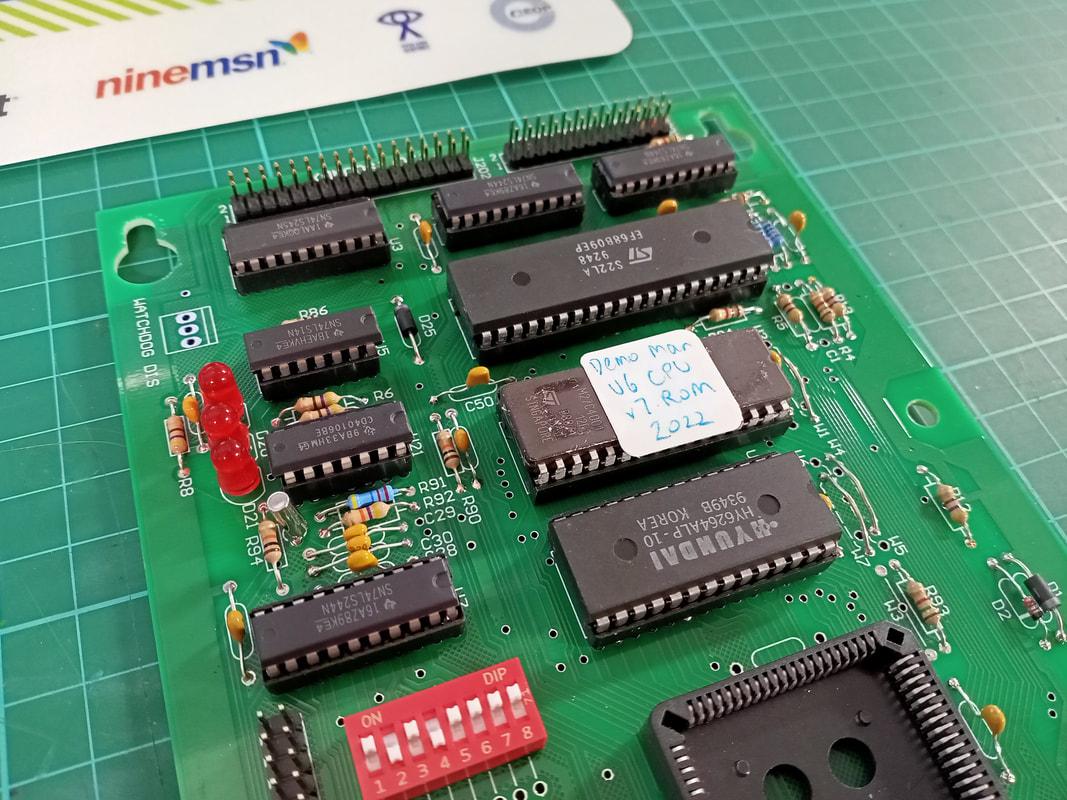
Now comes the fun part - soldering everything in place. There's not much to say about this process other than it's important to take your time and ensure you complete the board in a systematic manner. You can either do it by component type, or section of the board. Either way, don't mix up your components and put them in the wrong place! Pinwiki has some helpful images including signal maps of the board, as well as part layouts for the areas most commonly affected by corrosion. I used both of these resources to make sure I was putting things in the correct place and to check continuity was present where it needed to be. The game manual will be a great reference for this, too. I did a couple of upgrades while I was at it. I installed a coin cell lithium battery holder to replace the original battery holder, and upgraded the capacitor at C31 to a higher voltage rating as this capacitor is often a cause of issues. I also socketed all of the integrated circuits, which will make repairs much easier in future. Some people only bother to socket U20 and the game RAM at U8. However, I figure that, if you are populating the board from scratch, it is just as easy to solder in a socket as it is to solder the chip. I burned a new game ROM for Demolition Man (Williams, 1994) and put it in my game to test. Surprisingly, no issues! It worked perfectly the first time. I ran it through all of the diagnostic tests for the lamps, switches, and solenoids, and everything worked as expected. Major corrosion repair: success! It's great that bare boards are readily available, as I like the idea of using "factory" parts to rebuild a game rather than third-party reproductions. Note that the bare board featured above is the latest revision manufactured by Williams, and can be used in any WPC89 game (that is, any game prior to the WPC-S system). The advantage of this is you can use manufacturer schematics and manuals to troubleshoot and repair the board in future. These are not all available for reproduction boards, so be aware of this if you decide to purchase one. It's quite satisfying to take on projects such as these, carry out the repairs (or builds) and finally see them working in a game again. I'd like to say that this type of repair is uncommon, but it isn't. These are just a few of the examples which I took photos of during the process. There are many more which I didn't document. Some were successful, while others were not. Luckily we have the option to buy replacement boards when all other repair options are exhausted. It's a great time to be repairing pinball machines. However, every time someone puts alkaline batteries into the battery holder on the CPU board, there is a risk that they will be forgotten and will eventually leak. I always recommend that a battery replacement option is installed, each of which have their pros and cons, but are all better than the original battery setup. If this post convinces at least one person to check their backbox for battery leakage, then I'll be happy. One CPU board checked, is one less I'll have to repair!
0 Comments
Leave a Reply. |
About
Here you will find logs of our pinball and arcade machine restorations, repairs, discussion about general pinball and arcade topics, as well as recounts of our random pinball adventures.
Check back regularly for updates! Blog updates
Archives
May 2024
Categories
All
Donate

Running this website is a hobby for me (just like pinball!). I like being able to show off my restoration work so everyone can learn from it and potentially fix their own machines. If you enjoy reading the site's content or it has been helpful to you, please consider donating to offset some of the website's operating costs. |
||||||


 RSS Feed