- Published on
Last Action Hero
- Author
-
-
- Name
- Posts
- Posts
-
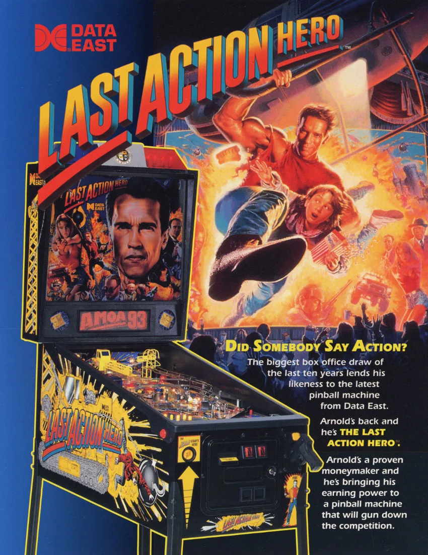
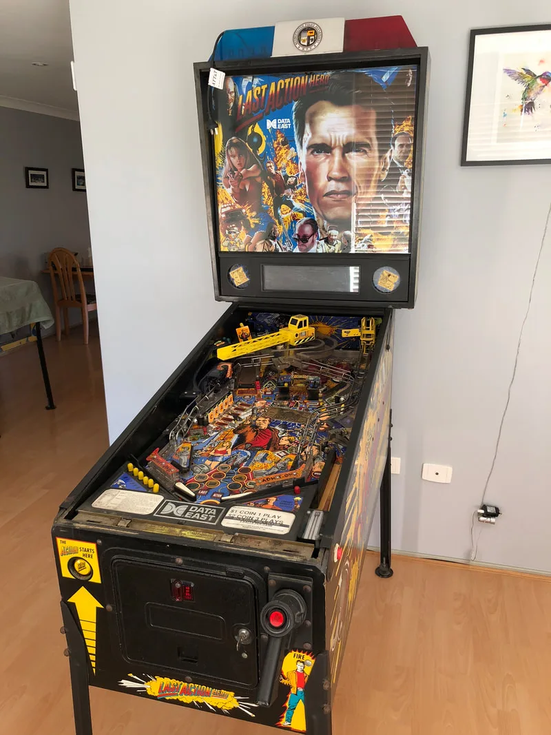
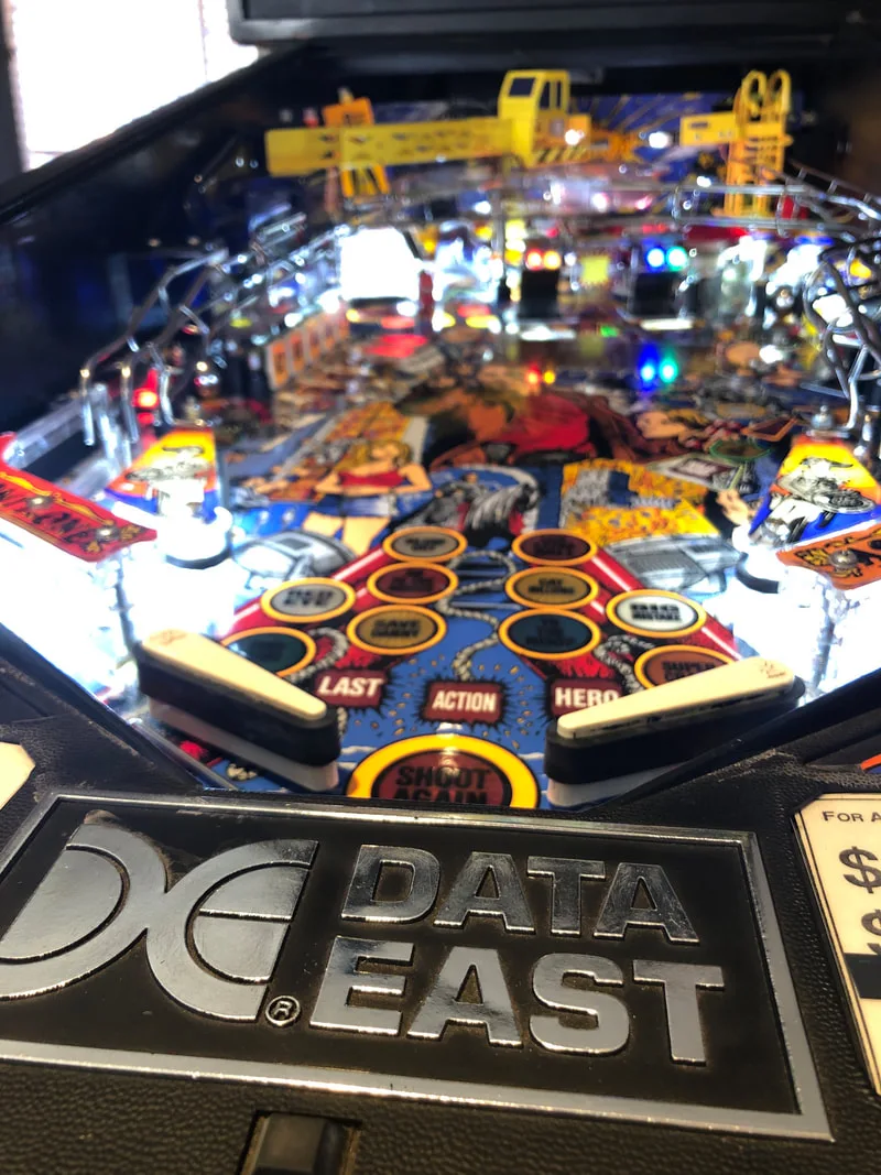
Last Action Hero (Data East, 1993) came to me as a restoration project for a customer who had had the machine for some time but was moving it to a new location. He wanted it to be fully working so he could set it up in his factory. The machine was relatively functional, but had a few issues that required extensive repair. I have a soft spot for Data East machines, so I was keen to take this one on and see how a full restoration would make it pop like new again.
- Timber in good condition.
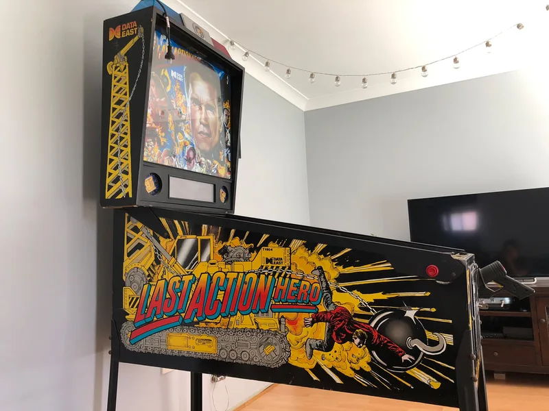
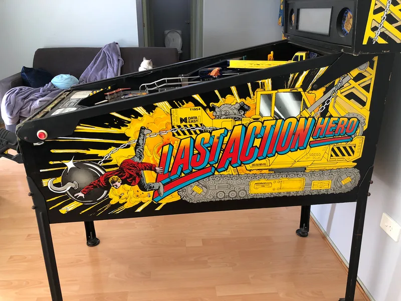
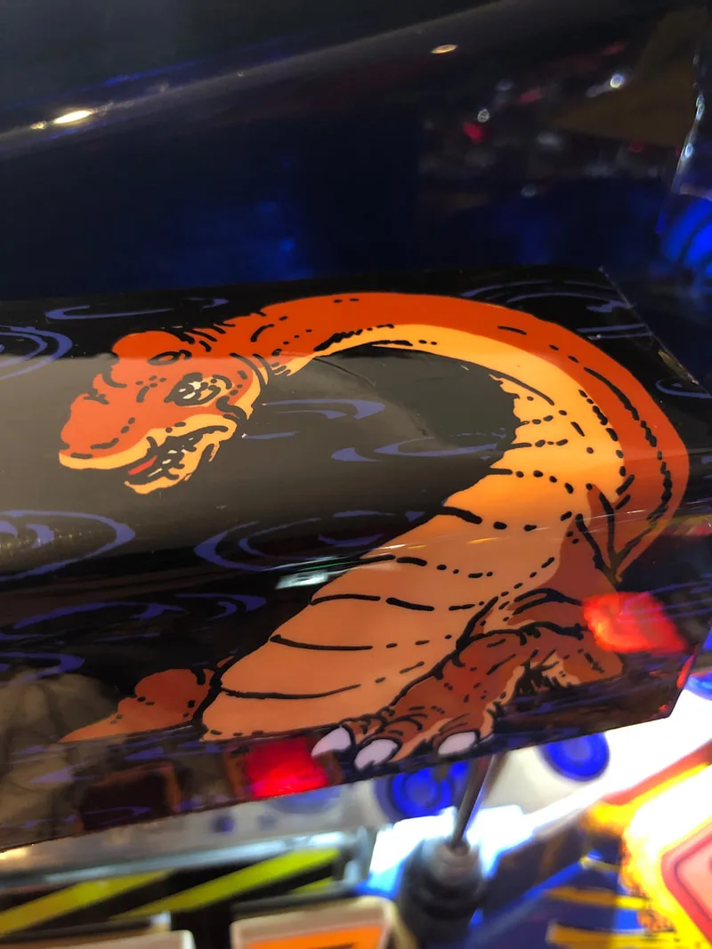
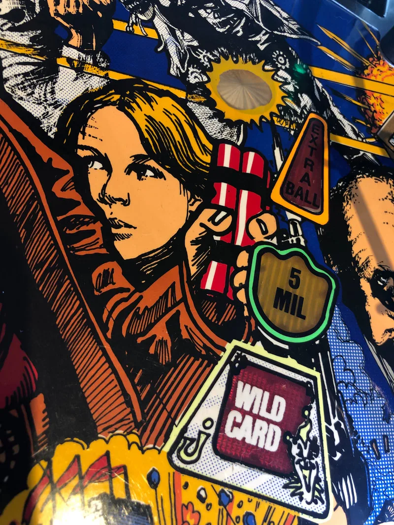
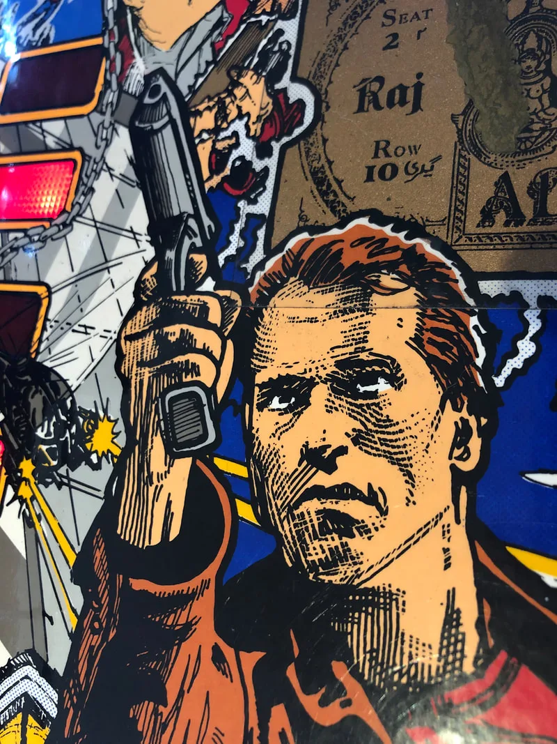
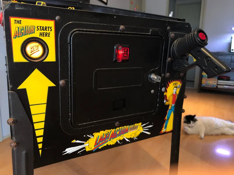
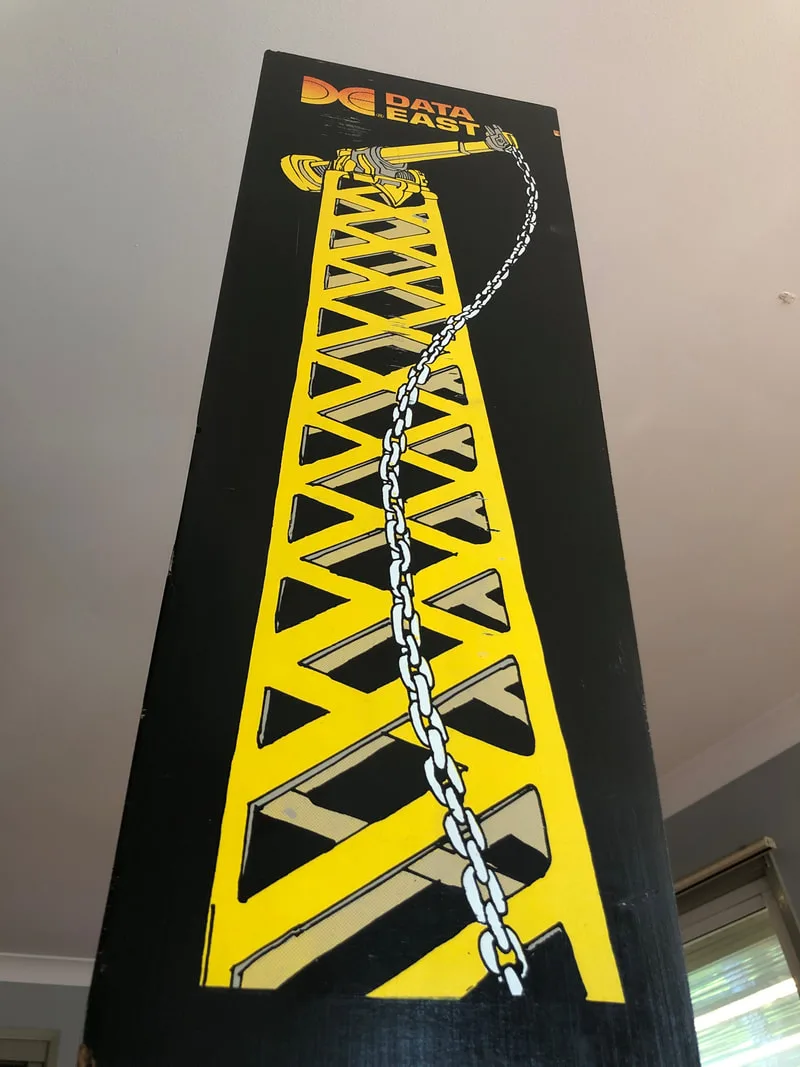
- Side artwork in good condition.
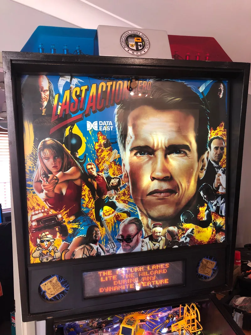
- Translite in good condition.
- Legs in average condition.
- Playfield was very dirty.
- Consumables (rubbers and lamps) in good condition.
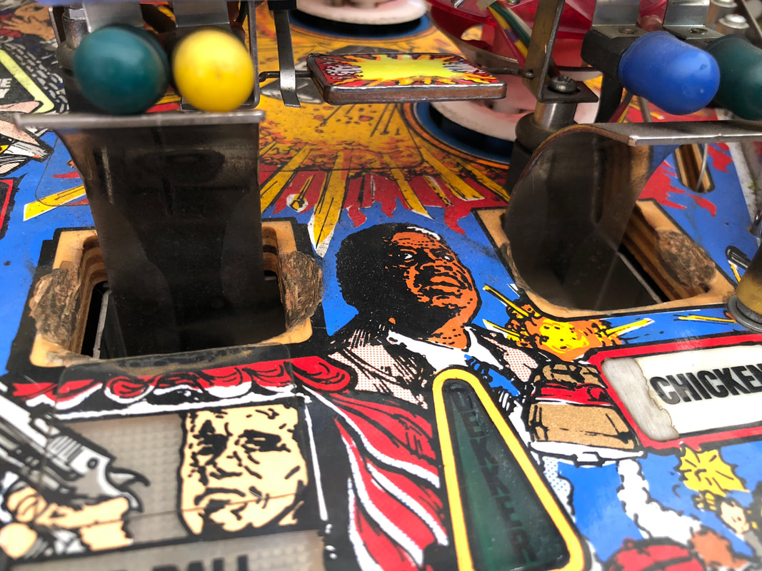
- Playfield artwork worn around the golden ticket. Significant wear around scoop holes.
- Plastics in average condition; some broken.
- Playfield mechanisms/toys in good condition.
- Some strange playfield modifications (switch locations).
- Drop targets did not drop consistently.
- All mechanisms and assemblies in average condition. Playfield magnets did not work.
- Consumables (coil sleeves, flipper parts) dirty and in poor condition. Incorrect coil installed on right flipper.
- Playfield magnets were not working.
- Machine booted up and played.
- Some lamps not working.
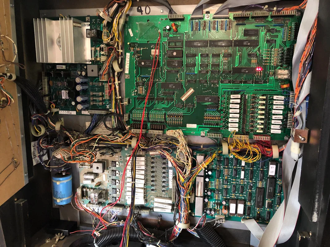
- Backbox circuit boards in good condition.
- Playfield and backbox wiring in good condition.
Disassembly
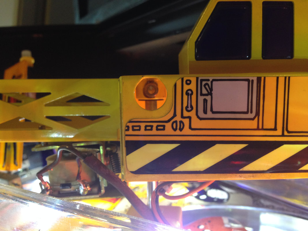
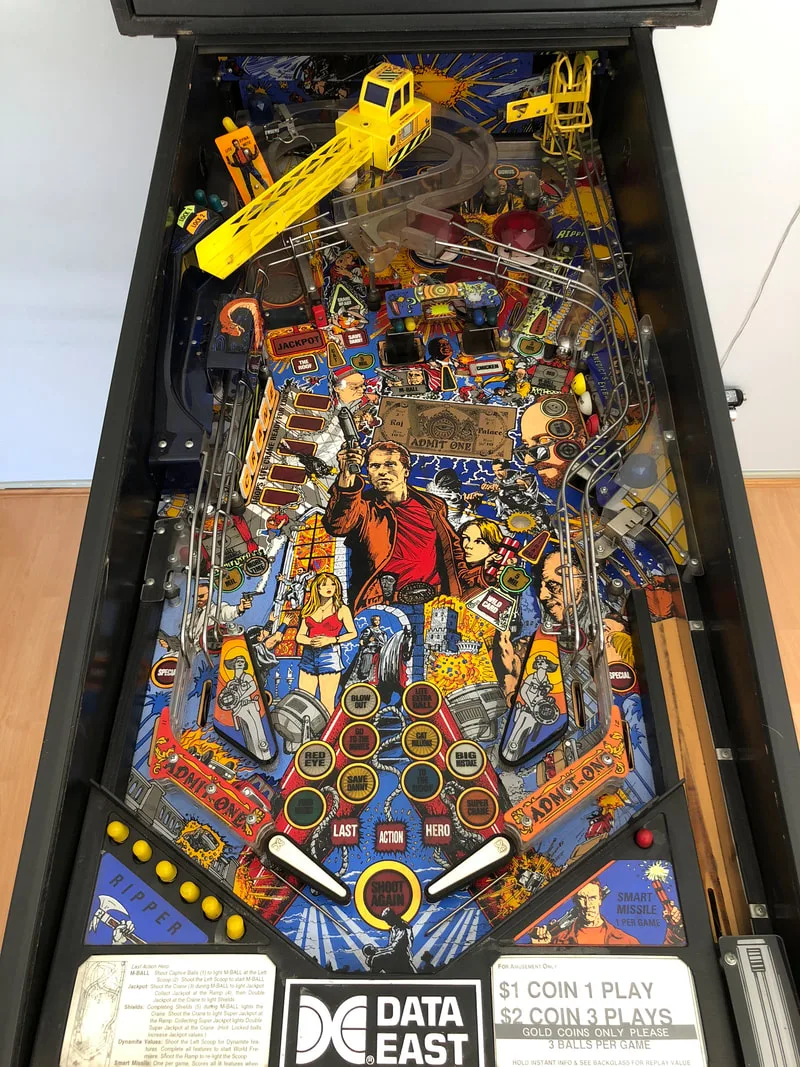
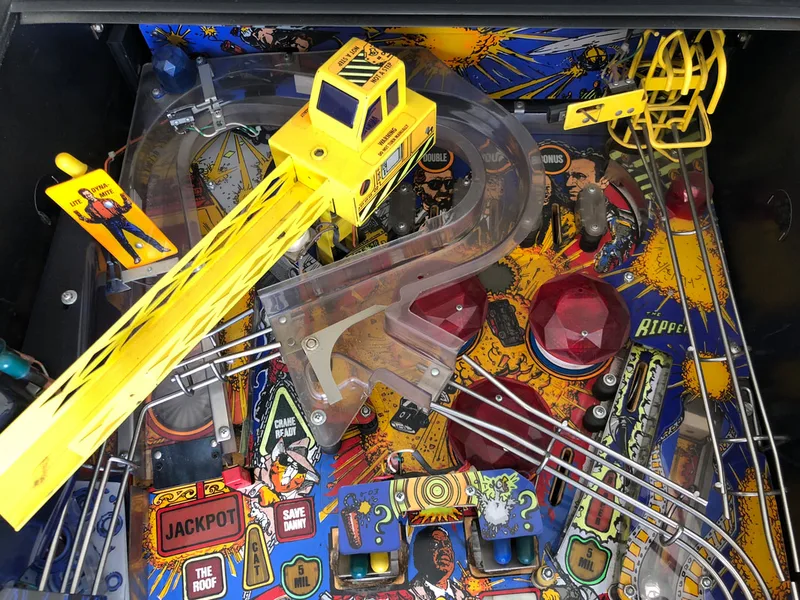
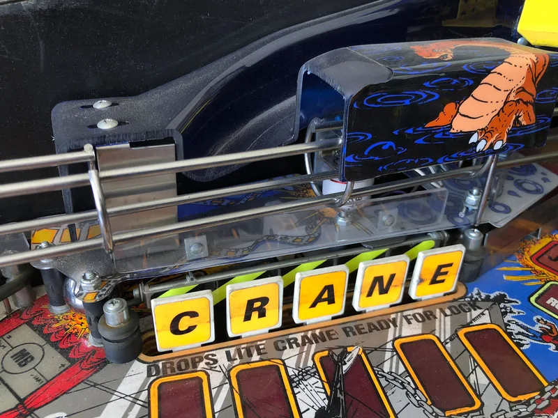
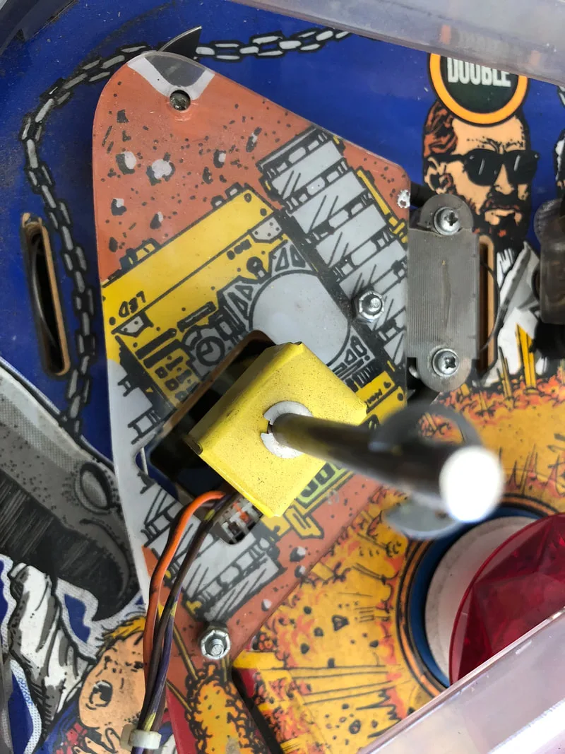
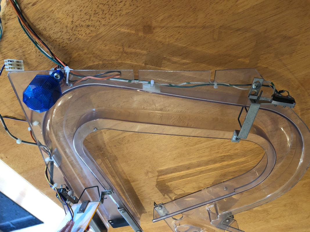
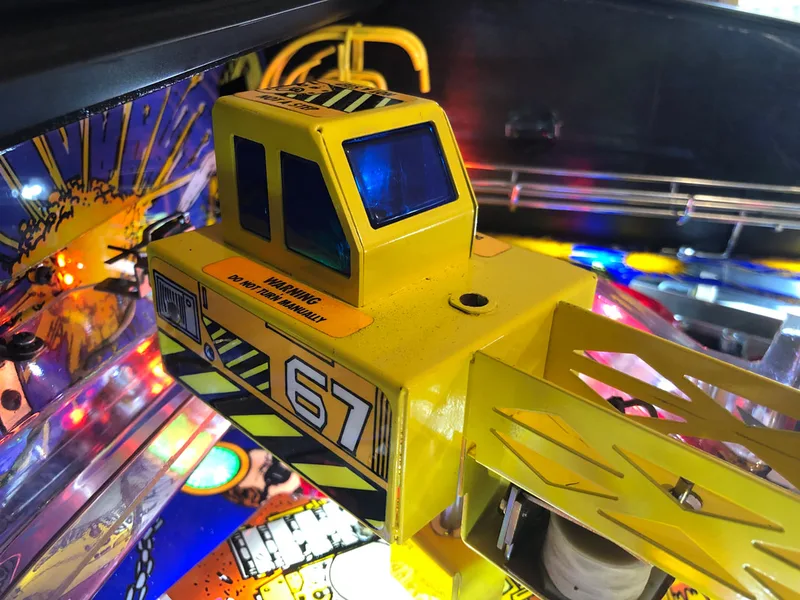
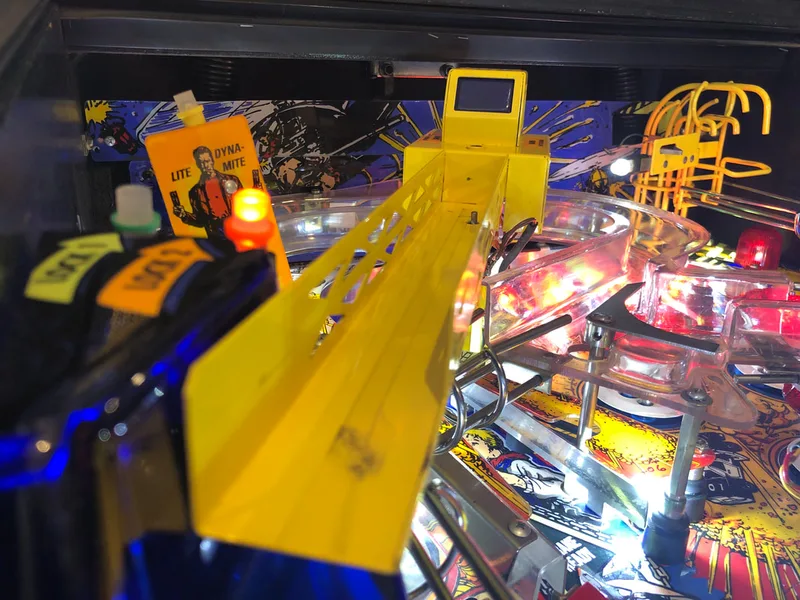
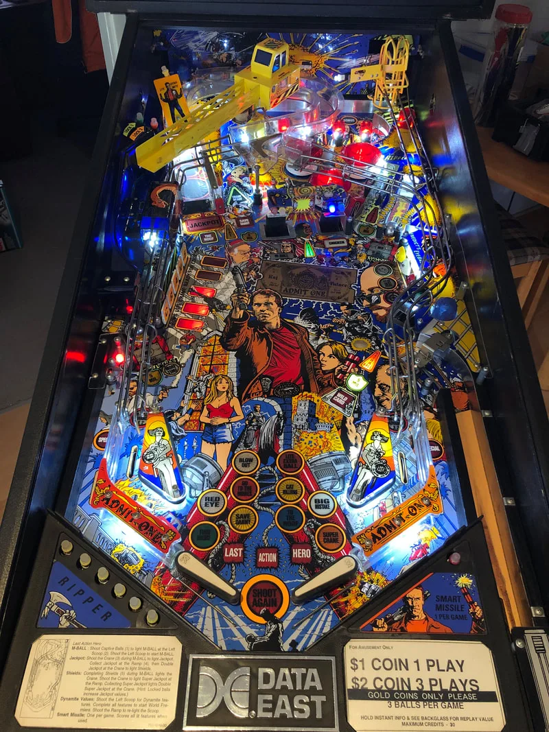
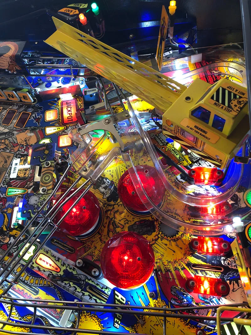
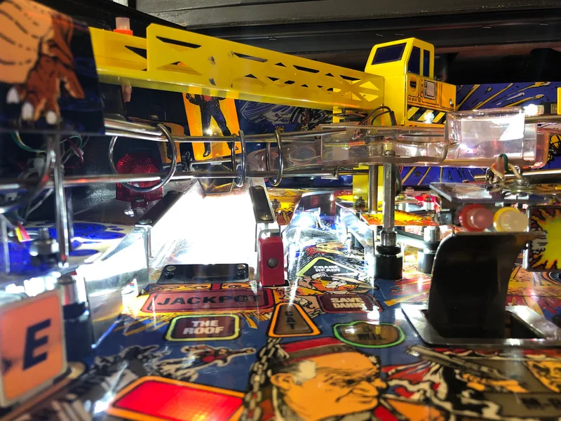
Last Action Hero, like a lot of Data East games from this period, has a pretty simple playfield with only a few major toys on it. There is one main ramp connected to a couple of wireforms, and a ball lock area on a separate plastic ramp. The crane sits on top of everything towards the top of the playfield. Disassembly is easy once you get the ramps and wireforms off. However, before you do that, you need to remove the crane. To remove the crane, unplug it from the underside of the playfield. There is a single connector used by the flashers and crane coil which snakes under the plastic beneath the crane and pops out near the crane motor. Once this is unplugged, you need to loosen the crane from the motor shaft. The crane is attached via a single grub screw, which you can loosen by inserting a hex key through the hole in the side of the main crane body. Once loose, the crane just lifts off the shaft. Note that you may need to loosen the plastic under the crane to wiggle the connector through. The rest of the game is fairly easy to disassemble and service.

Grub screw securing the crane to the shaft.
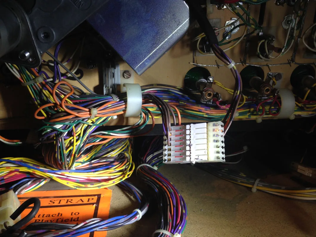
Crane connector under the playfield.

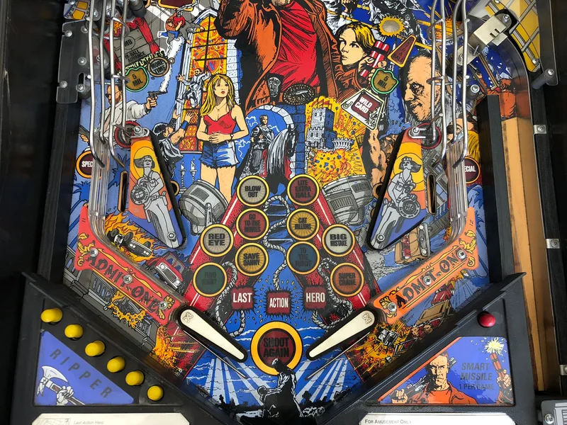
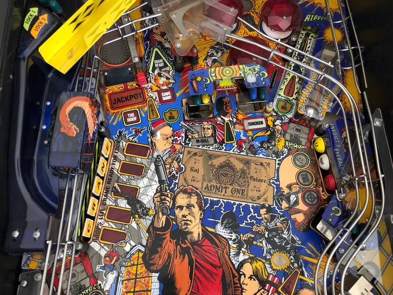
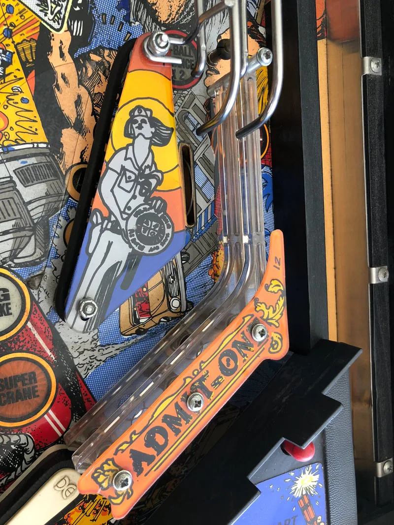
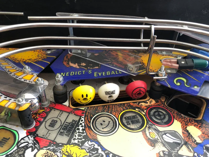
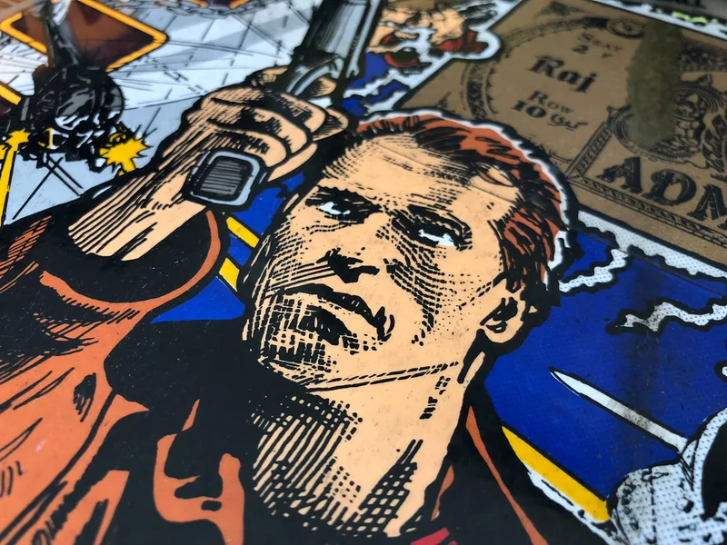
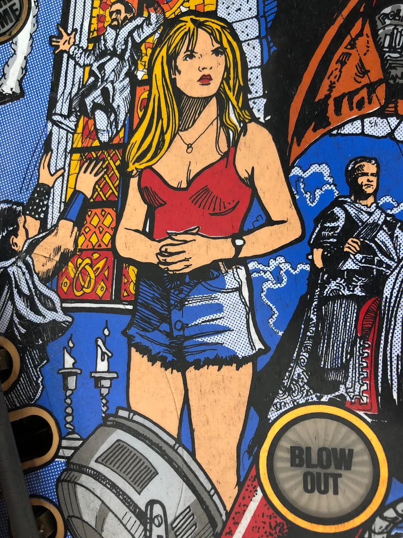
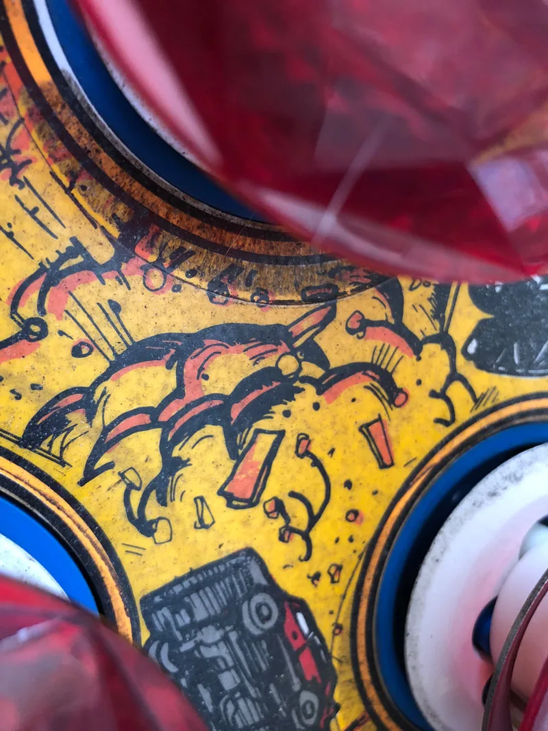
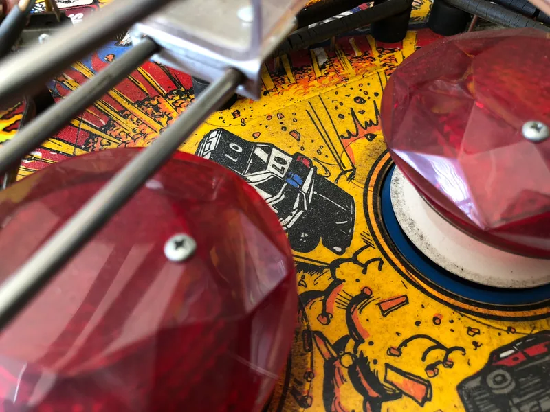
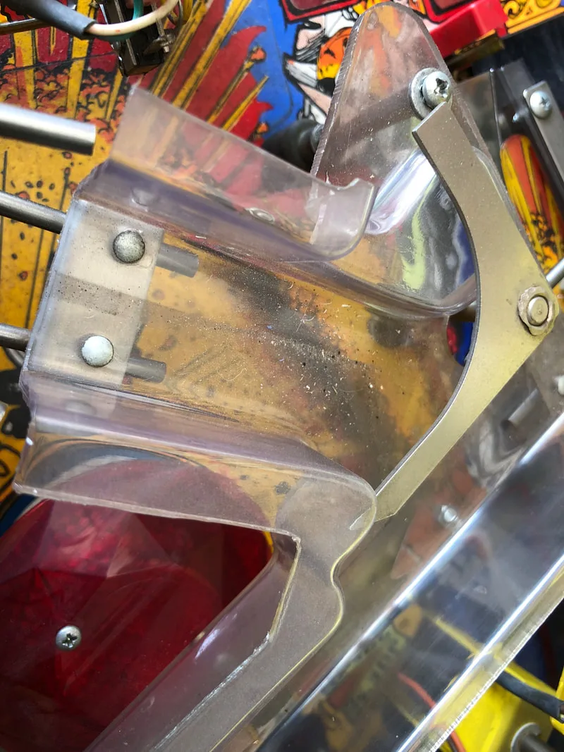
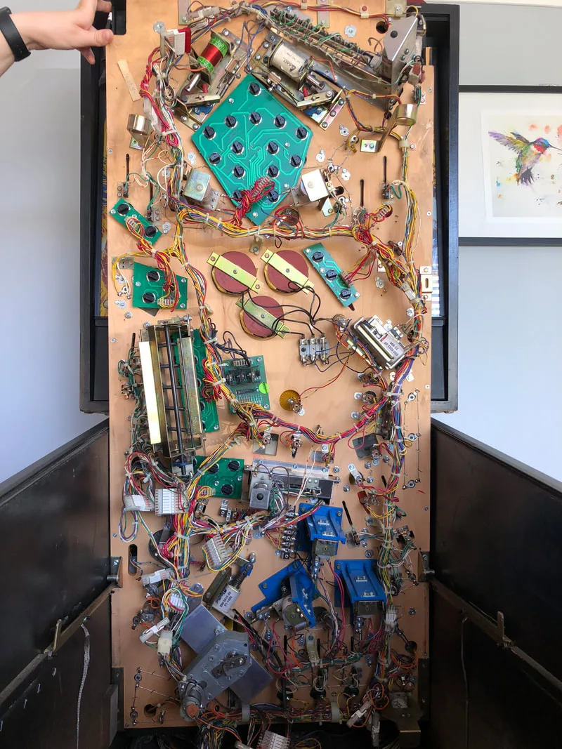
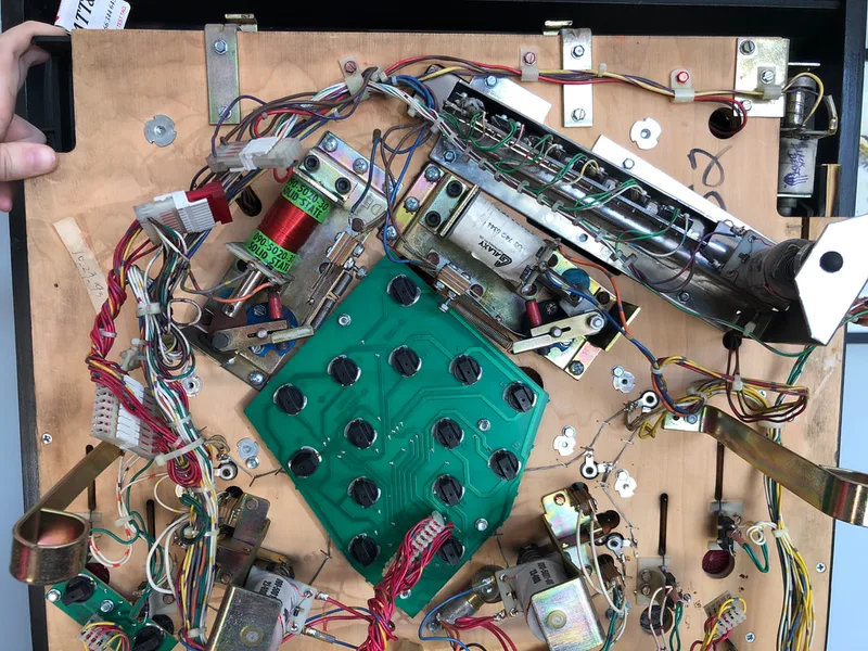
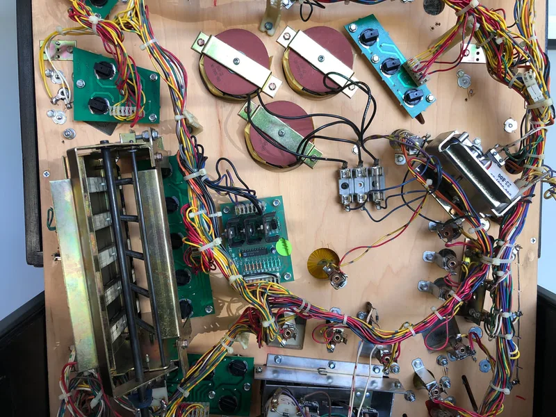
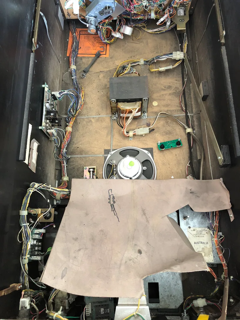
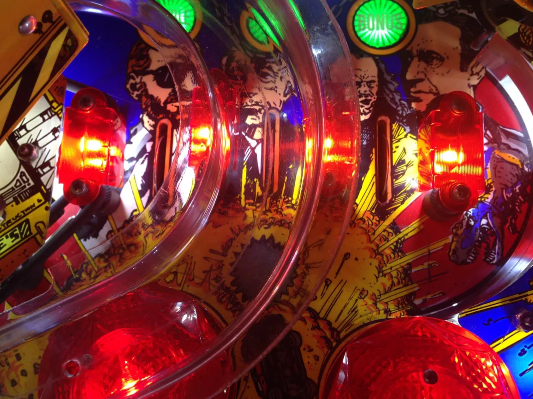
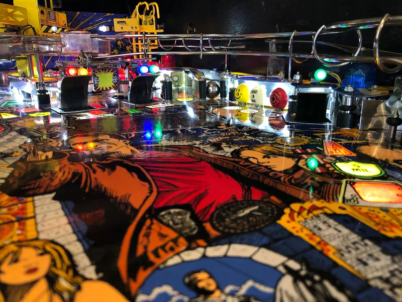
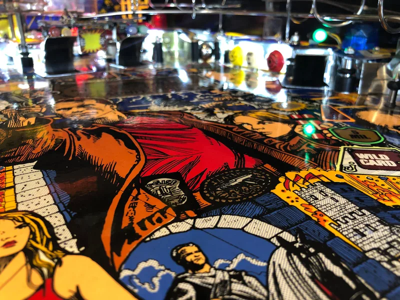
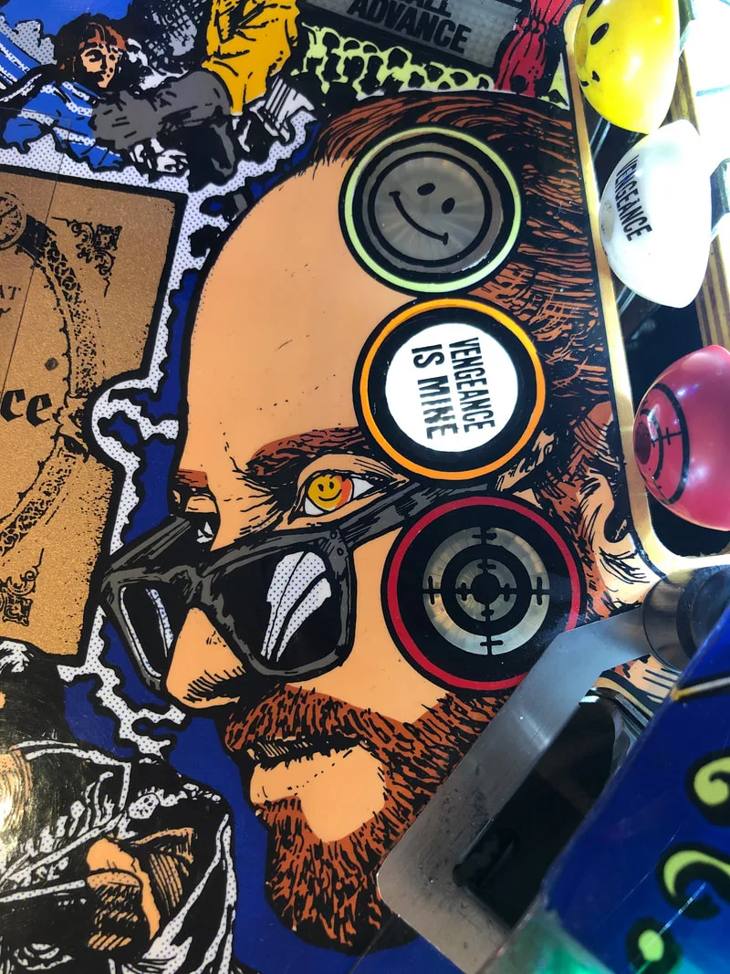
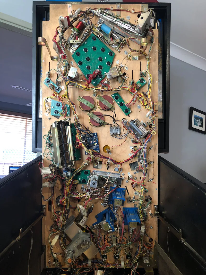
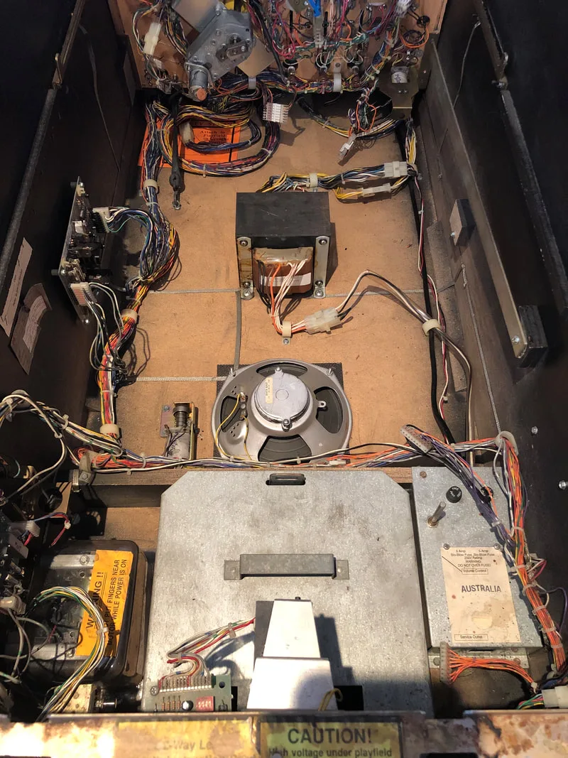
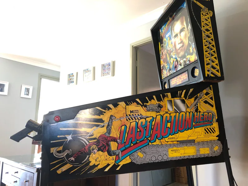
Here are some shots of the machine's initial condition and some of its disassembly.
After disassembly, the game went through my standard restoration process to get it playing and looking like new. During the restoration process, I dealt with a number of issues, described below.
Tips & Troubleshooting (click on sections below to view details)
While looking in the manual I noticed that somebody had actually marked the lamps in column 8 and written down the column drive wire colours. It looked like somebody had noticed this problem a while ago, but never actually got around to fixing it. That's why I love reading through game manuals - you never know what kind of helpful scribbles you'll find!
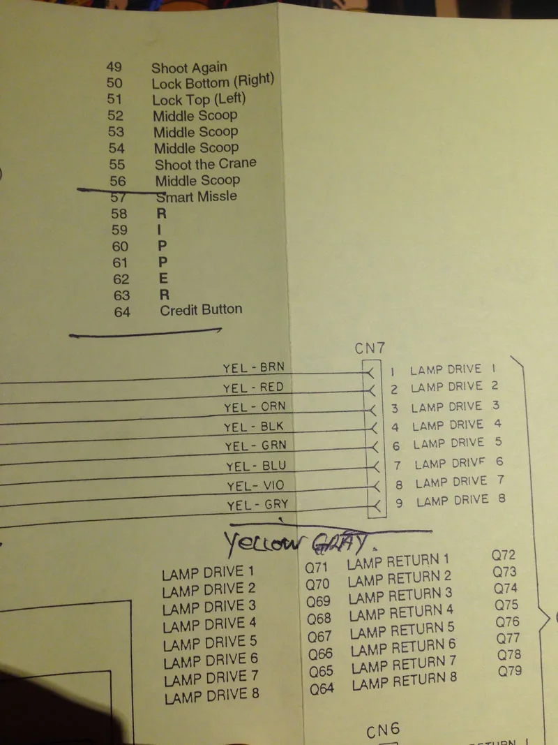
Scribbles in the game manual highlighting all of the problem lamps.
So, now it was time to fix the issue after who knows how long it had been affecting the machine for. I took the MPU board out of the backbox and started testing all of the lamp transistors. Sure enough, Q64 gave suspect results, and this is the transistor that controls column drive 8, where all of the non-working lamps were located. I whacked in a new TIP42c (Jaycar), and the lamps were back to working again.
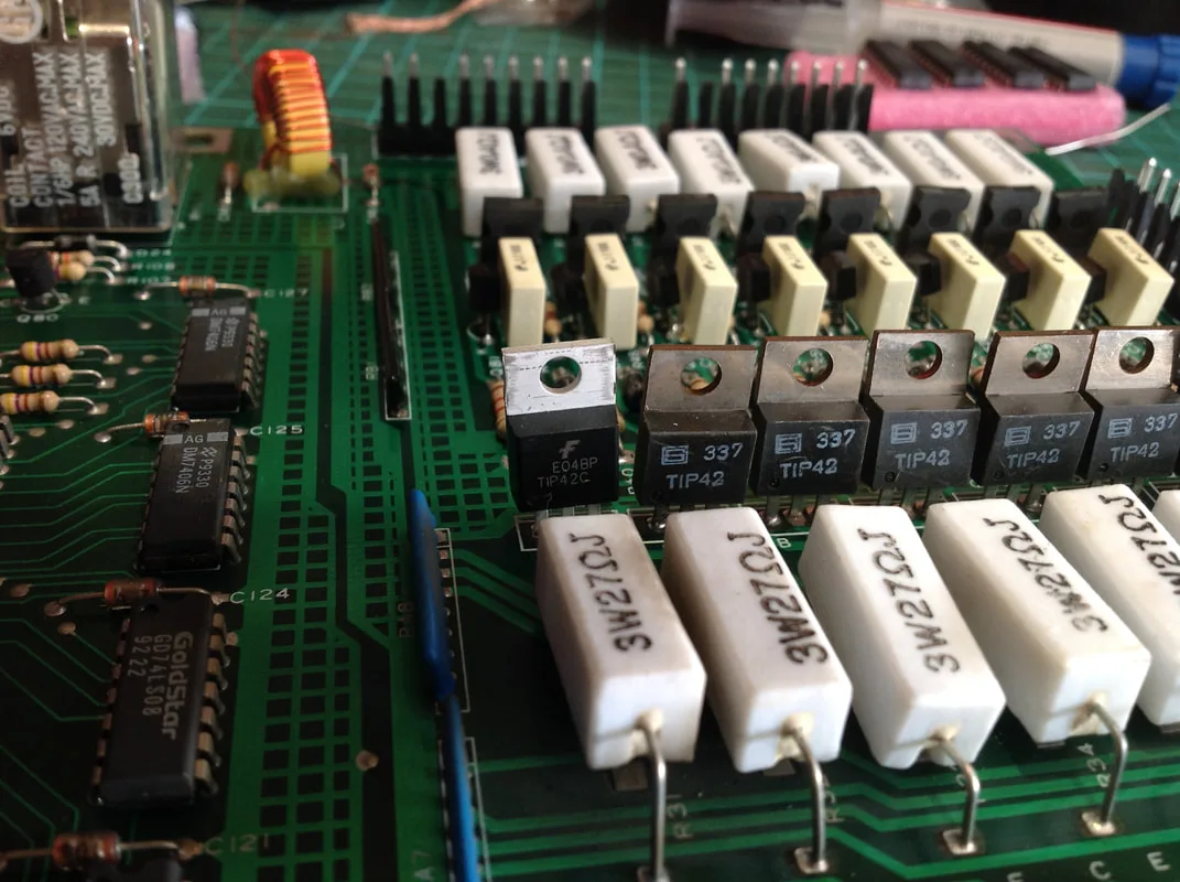
New lamp driver transistor after installation.

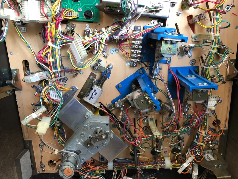
The magnet driver board is a simple board mounted underneath the playfield which holds an integrated circuit, resistors, three transistors and associated diodes. Power from the CPU board is sent to the magnet driver board, which then turns each of the three playfield magnets on and off during multiball modes. Each of the magnets is separately fused. It's a pretty simple circuit, or so I thought.
Initially, only one of the game magnets was working and once I lifted the playfield, it was pretty clear to me why. There was only one fuse in the fuse holder! "This will be an easy fix!" I thought. Funnily enough, things never go to plan whenever I say that.

View of the playfield underside showing three magnets, fuse block (with only one fuse) and magnet board (with green sticker).

With new 3A fuses in the fuse holders, I turned the game on, and started multiball. Multiball started without issue, and I even saw a magnet flick a ball around initially, but then the magnets just stopped working. After playing for another minute, I was down to the last ball, and shot it into the right scoop. However, it didn't come back out. The game awarded points for hitting the scoop, but the coil wasn't firing the ball back onto the playfield. Then I discovered that multiple other coils weren't working, either. I took a look in the backbox and found that fuse F5 on the playfield power board had been destroyed. As there had not been as issue with this fuse until I replaced the magnet fuses under the playfield, I suspected that the magnets were to blame. I replaced the F5 fuse, turned on the game, and saw it blow again straight away.
I started to troubleshoot this piece by piece. I removed the magnet fuses under the playfield except for one. I left the single fuse that was present when I first lifted the playfield. With that fuse installed, one magnet worked, and F5 didn't blow. Progress! I installed a second magnet fuse, and this time, I also held a ball on the playfield above the magnet controlled by that fuse. When the game turned on, the magnet locked on, grabbing the ball for a few seconds. The fuse under the playfield associated with that magnet blew, and the magnet turned off again. I repeated this process with the third magnet, and it also locked on before blowing its fuse. So, it seemed that two of the playfield magnets were locking on as soon as they received power.
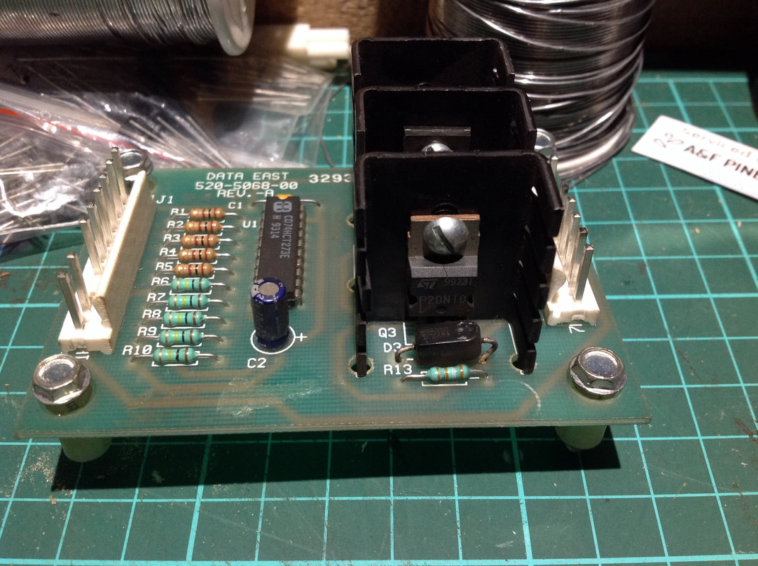
Now I turned my attention to the magnet driver board (part no. 520-5068-00). This board has multiple revisions, and was used in a small number of games. Last Action Hero was the first game to use it, followed by Guns N' Roses (Data East, 1994). A revised board (part no. 520-5068-01) was later used by Stern in a few games such as Indiana Jones (Stern, 2008) and Family Guy (Stern, 2007) to drive extra coils and lamps. If you search on Pinside, you'll find countless threads regarding issues with the infamous magnet board. This board was under-engineered, and it is common for it to blow fuses, destroy transistors, or simply not work at all. Part of this is due to problematic components on the board, and part of it is because the board is mounted on the playfield instead of the backbox, which makes the data signals sent to the board susceptible to interference. The universal fix in most of these cases simply appeared to be replacing most of the components on the magnet board with beefier parts. Clay's guide has a small section devoted to this board, and his advice is to replace the transistors with logic level MOSFETs (IRL540s recommended), as well as the 74HC273 integrated circuit.
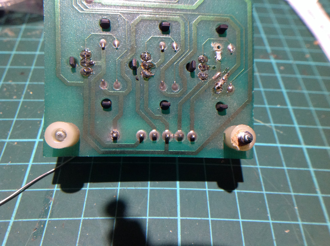
Original board before repair. Note the original FET (P20N10L) with some odd diode installed at D3...
Another issue - a cracked solder joint at the output connector (pin 1, at left).
I installed MOSFETs on the board (eBay), replaced the diodes associated with each FET, and also replaced the integrated circuit with a 74LS273 (Jaycar) in a socket. One of the solder joints for the output connector was also cracked, so I reflowed it, and reflowed the rest just in case. Pretty chuffed with myself, I reinstalled the board into the game and replaced the magnet fuses. I started the game up, entered a multiball, and boom! Two of the magnets locked on again and blew their fuses. I took the magnet board back out, and sure enough, I found that two of the transistors had shorted internally, grounding the magnet coils permanently. Hmm. I did some further research. Clay's guide indicated that the magnets may lock on due to noise interfering with the clock signal that controls the integrated circuit on the magnet board. Adding a 0.22 uF capacitor across pin 10 and 11 should filter out this noise, so I added a capacitor. I also replaced the shorted transistors, checked my other solder work, and confirmed everything was OK.

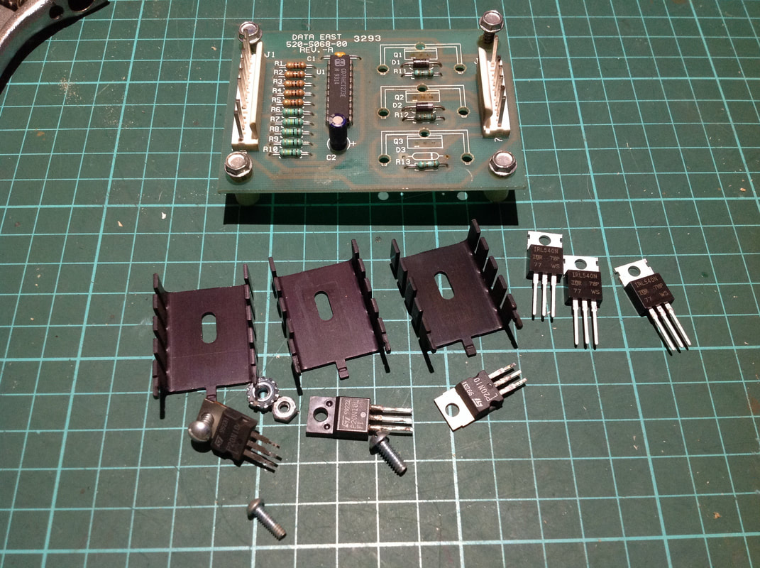
Removal of the original P20N10L FETs for replacement with beefier IRL540 FETs (at right).
Again, I replaced the magnet fuses, installed the freshly repaired magnet board, and started a game. Once again, the magnets locked on, and two of the MOSFETs shorted out again. I was getting frustrated by this point. I had replaced all of the problem components with brand new ones, but still had the same issue. Moreover, it only affected two of the three magnets. Each of the magnets was in good condition and all returned the same resistance reading. At this point I realised why there as only a single fuse in the fuse block for the magnets when I first opened the game. This fused the single magnet that did work properly. A previous owner had obviously figured out that two of the magnets were causing issues, and just removed their associated fuses instead of trying to fix the problem.
I spent hours trying to find the source of the problem. I replaced the shorted transistors countless times. I reflowed solder. I even replaced the new integrated circuit with another new integrated circuit, thinking I got a dodgy one. No dice!
I started looking at the CPU, considering that it may be sending incorrect signals to the magnet board. Interestingly, the magnet board is driven by the display strobe 7-segment 6821 PIA located at B11, rather than the PIA at F4. The PIA at 11B sends signals to the magnet board via connector CN3. To test the PIA, I erased the game ROM and replaced it with an image of Leon's test ROM. Leon's ROM tests the output of each PIA which can be seen as a voltage oscillating from 0-5 volts on each output pin. One exception is pin 9 at PIA 11B, which is tied to ground. All of the pins tested good, which proved that the CPU board was OK.
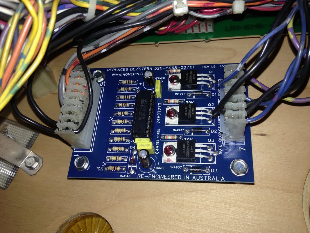
Back at square one! Thankfully, there was a final solution. I opted to replace the magnet board with a brand new one made by Homepin (Johns Arcade). This board is an updated and improved version of the original, with upgraded components and improved circuit design. While I normally hate replacing any circuit board, and prefer fixing them instead, there was nothing left for me to replace on the original board.
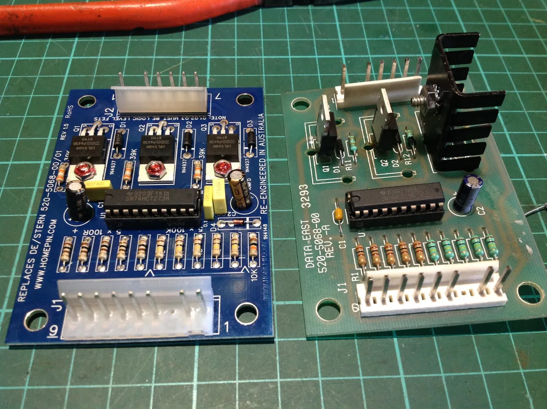
New Homepin magnet board (left) compared to original magnet board (right).

The Homepin board comes with an extra capacitor which can be installed at C2. This capacitor is equivalent to the noise filtering capacitor that I installed across pins 10 and 11 of the integrated circuit on the original board. The Homepin board also has a couple of extra capacitors and diodes that are not present on the original board. Other than that, it is a direct plug-and-play replacement.
So, did it work? Yes. Yes it did. Once I installed the board and replaced the magnet fuses, everything worked perfectly. This is one of those rare occasions where I was never able to figure out the source of a problem, and even though the issue was fixed in the end, it took me another year to finally figure out how to repair and upgrade the magnet board properly. You can read about the upgrades in my Guns N' Roses repair blog. So at last, the magnet board saga came to rest!

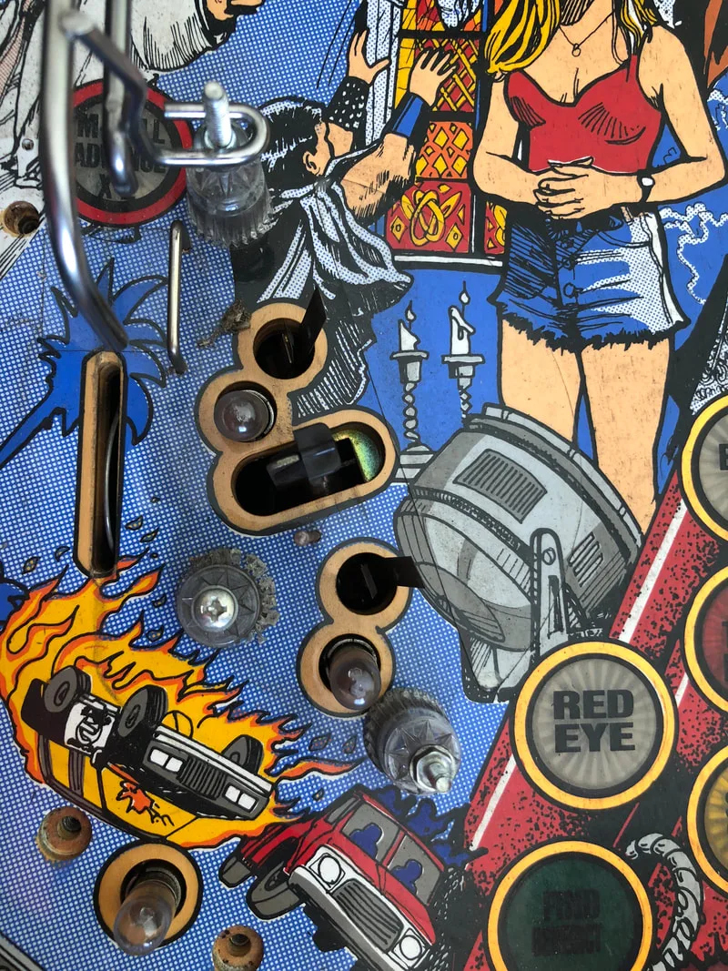
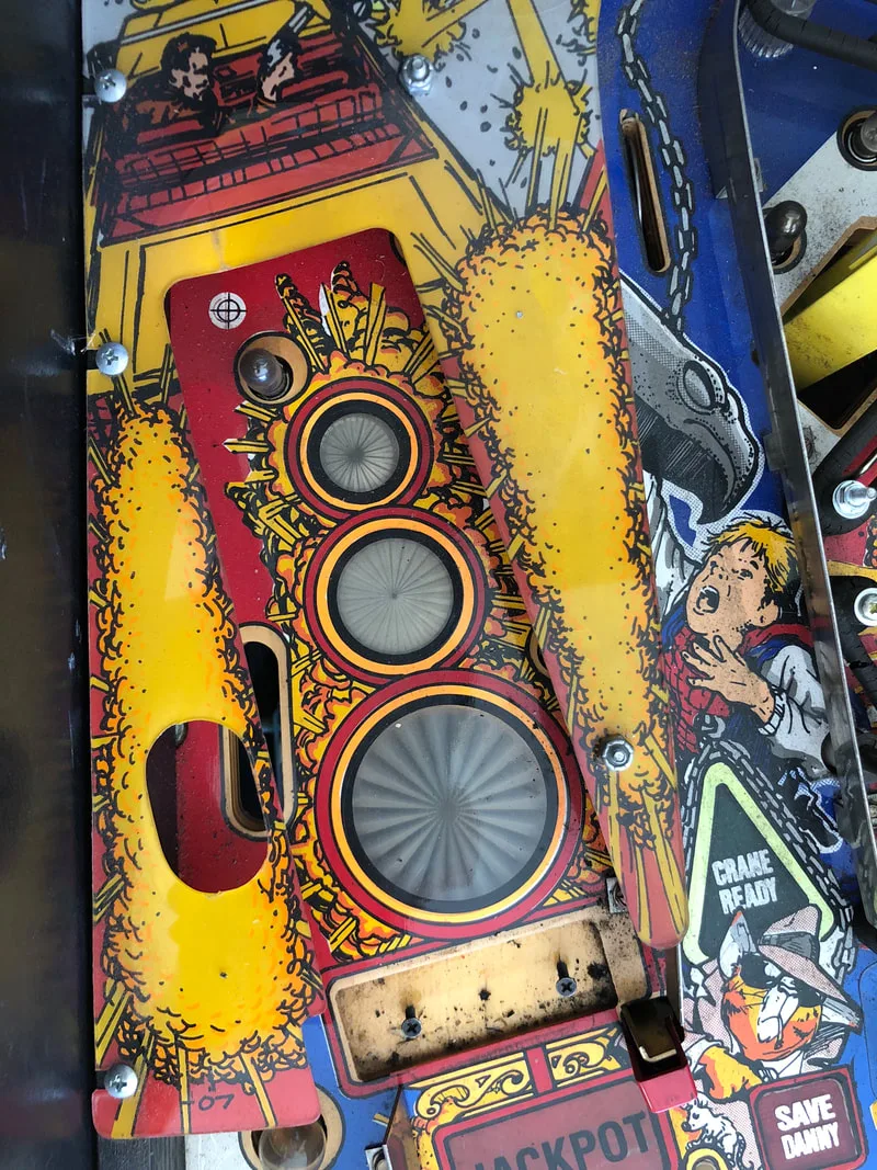
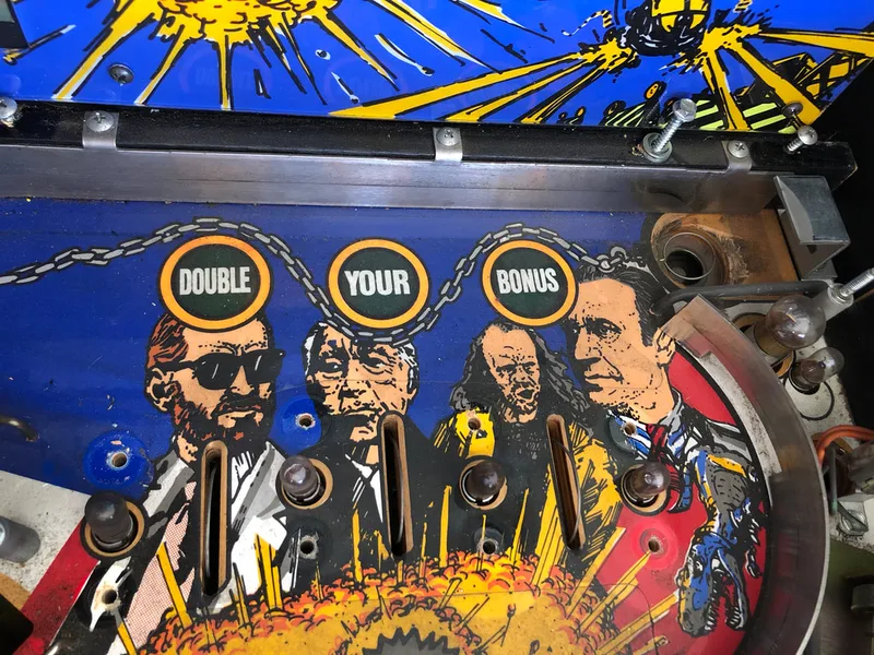
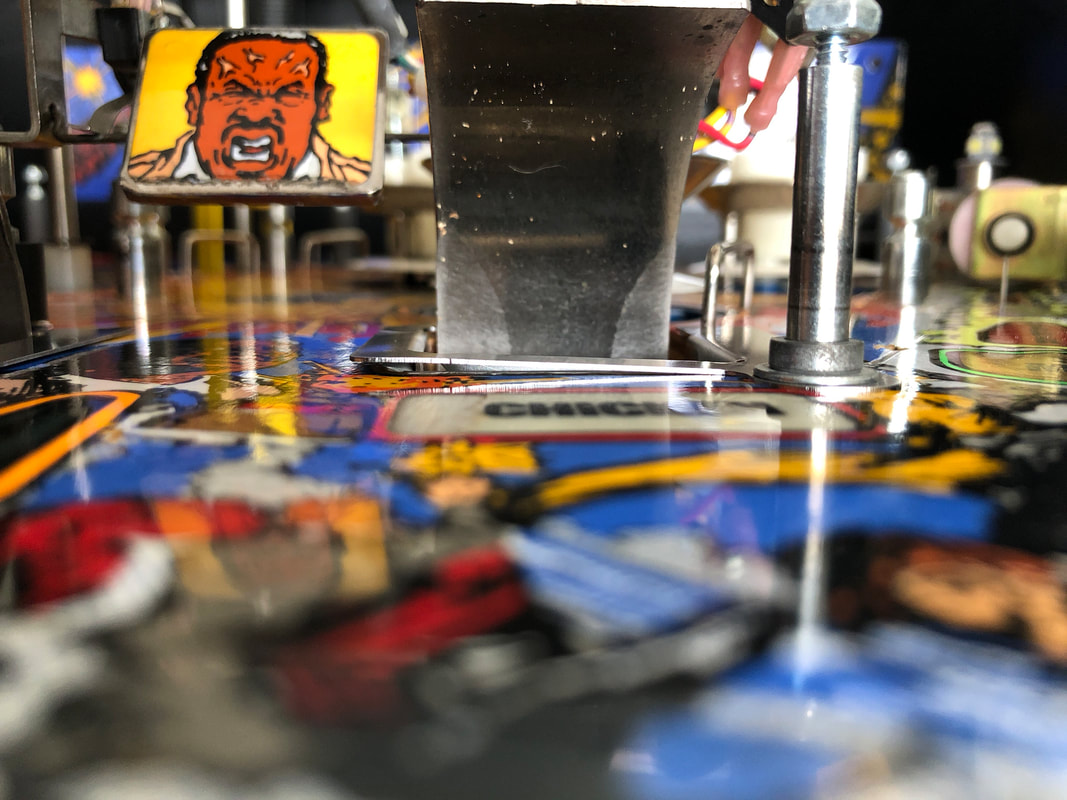
Scoop hole wear on the left and centre scoops.
The first step in this repair was to rebuild the timber around the holes. For this I use Selley's Knead It, as it is an easily workable putty which dries hard. So, once the area is cleaned and any loose timber fibres are removed, the putty can be applied. The rougher the surface is, while still being structurally sound, the better. Pad the putty in tightly. A little more is better than a little less, and it is simpler to remove excess rather than add more putty later. Once applied, leave to dry and check for cracks. Fill them in as necessary until you have a nice, solid fill.
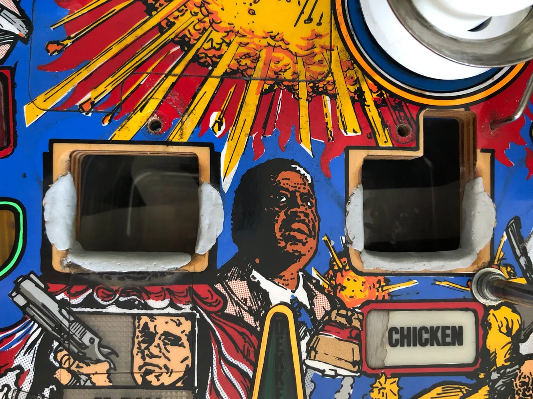
After application and drying of the filler.

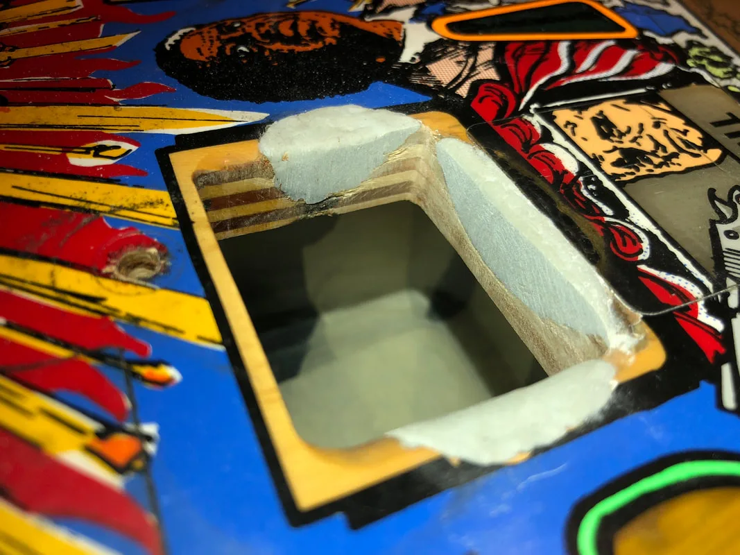
Square and rectangular scoop holes are great, because when it comes time to sand the filler flush with the wood, you can use a piece of timber with some sandpaper wrapped around it, or a small sanding block, to get a straight edge in the tight space of the scoop. This lets you get into the corners of the scoop very nicely. You can bevel/rout the edge of the timber piece to get a softer or sharper corner, too.

Using a piece of timber and sandpaper to form the edges of the scoop hole.
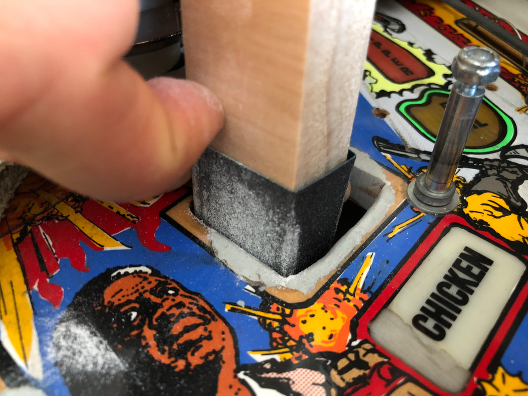
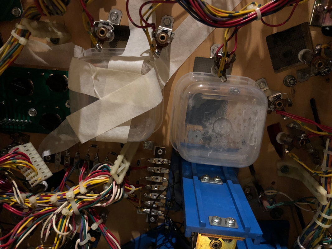
This is a good idea on Last Action Hero as you have three holes to work on, so doing it manually with a piece of sandpaper gets tedious. The only disadvantage to this method is that it creates a lot of sawdust. Don't let this fall into the cabinet as you will be cleaning it out for hours afterwards. Luckily, the components under the playfield are placed such that you can insert a couple of small plastic containers under the holes, and tape them in place. These will catch all of the dust and filings while you sand. Neat-o!
A handy way to protect the cabinet from the wood filings and sawdust!
Once that's done, you should have some nice straight edges to work with.
The left scoop hole during repair. The long edge has been sanded flush with the playfield. Two more edges to go!

Once everything has been filled and sanded, you need to decide what you want to do with the repaired area. You can either cover up the filler with paint to match the playfield, or use a scoop protector to cover up the repair and protect the newly repaired area into the future. I highly recommend the second option. There are a couple of options for scoop protectors on Last Action Hero. Cliffy produces a set, but there are other options available, too. I used a set purchased from PSPA. I hadn't used any PSPA protectors before, so I wasn't quite sure what to expect. Unfortunately, they did not fit well. A metal tang of the protector sits between the underside of the playfield and the scoop assembly, but tightening the scoop assembly pushed on the protector and caused it to rise and bend. This created a lip at the scoop hole which can alter the path of the ball. No amount of fiddling seemed to be able to get the protector flush with the playfield. It also did not seem to fit as snugly as genuine Cliffy protectors seem to. Any movement in these protectors is bad as it will cause them to bend and impact the playfield they are supposed to protect.
Raised scoop protector edge.
Nevertheless, some protection is better than none, so these protectors will are better than leaving the timber bare. My recommendation would be to stick to genuine Cliffy protectors for the snugger fit. All in all, the repair went well, and these scoop holes have been bulletproofed for another couple of decades.
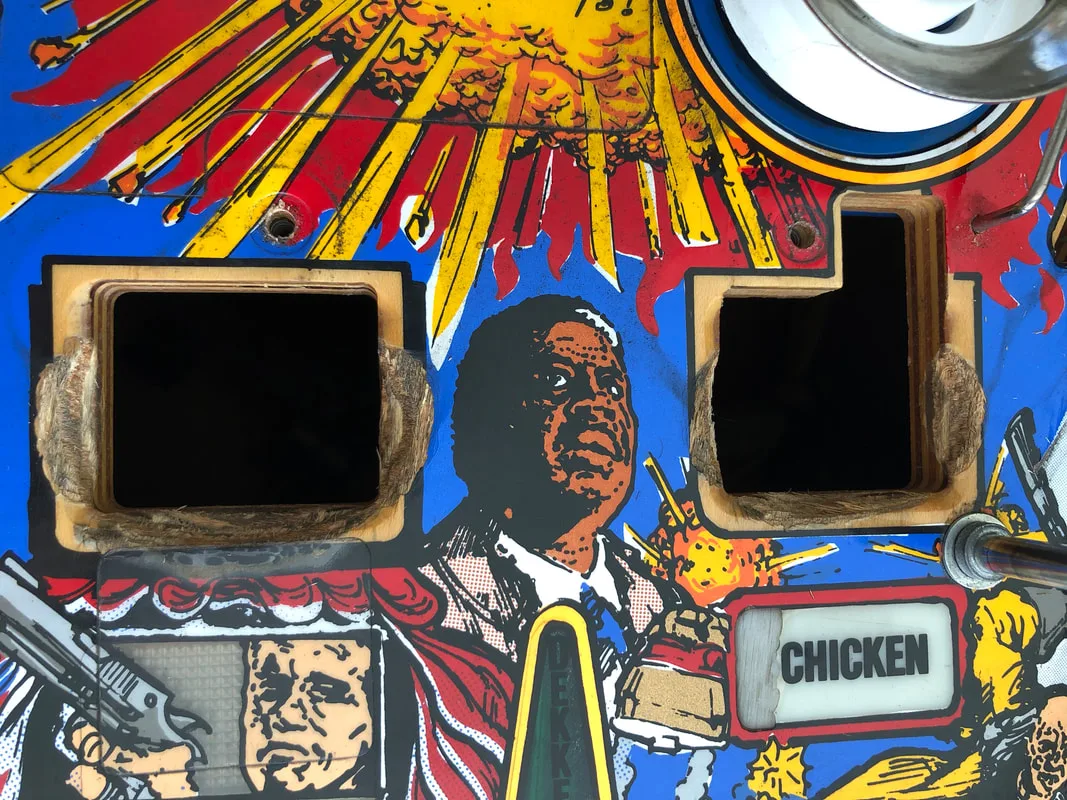
Before repair.

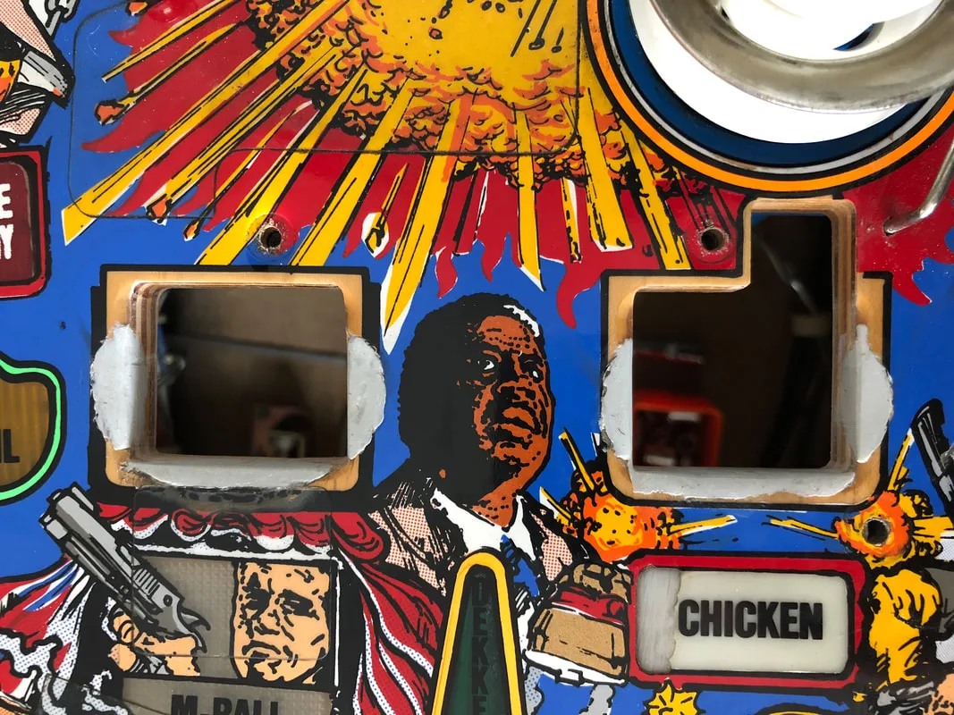
After repair.

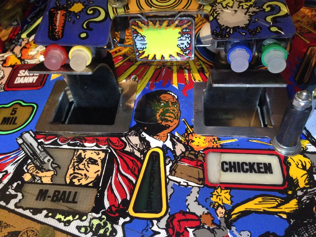
After fitting scoop protectors.

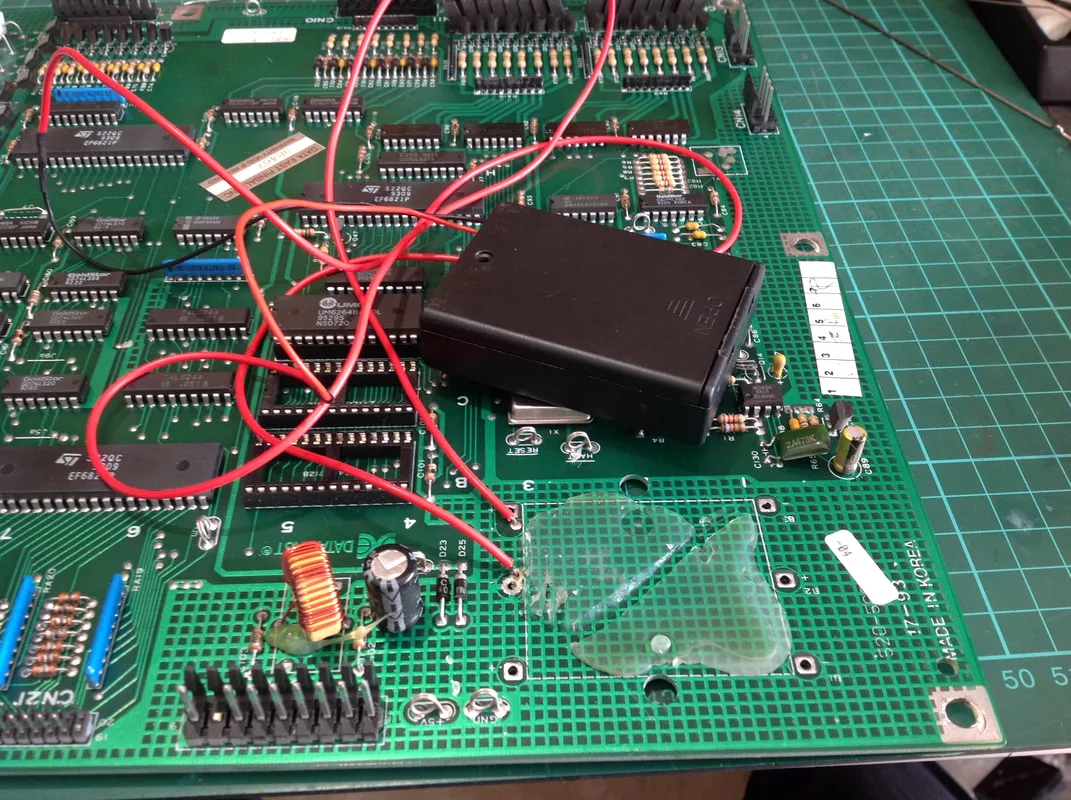
View of the glue on the underside of the old battery holder (new holder now installed).
New battery holder installed in the backbox.

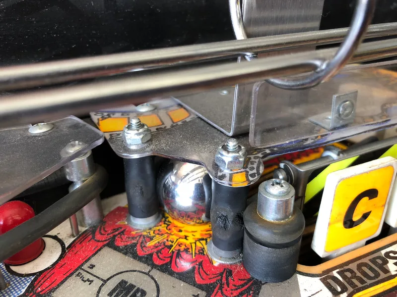
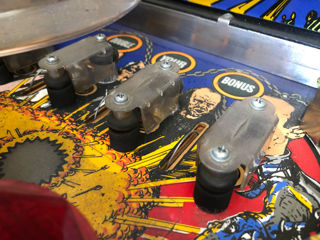
'A' drop target after being hit, refusing to drop down fully.

My first reaction to sticky or otherwise stubborn drop targets is to remove all of the targets and give them a clean. Usually, the build up of grime, coil dust, grease, and other improperly-deployed lubricants can gum up the target assembly quite badly. These targets were a little dirty and sticky, so I figured a clean was all that was needed to return them to normal.
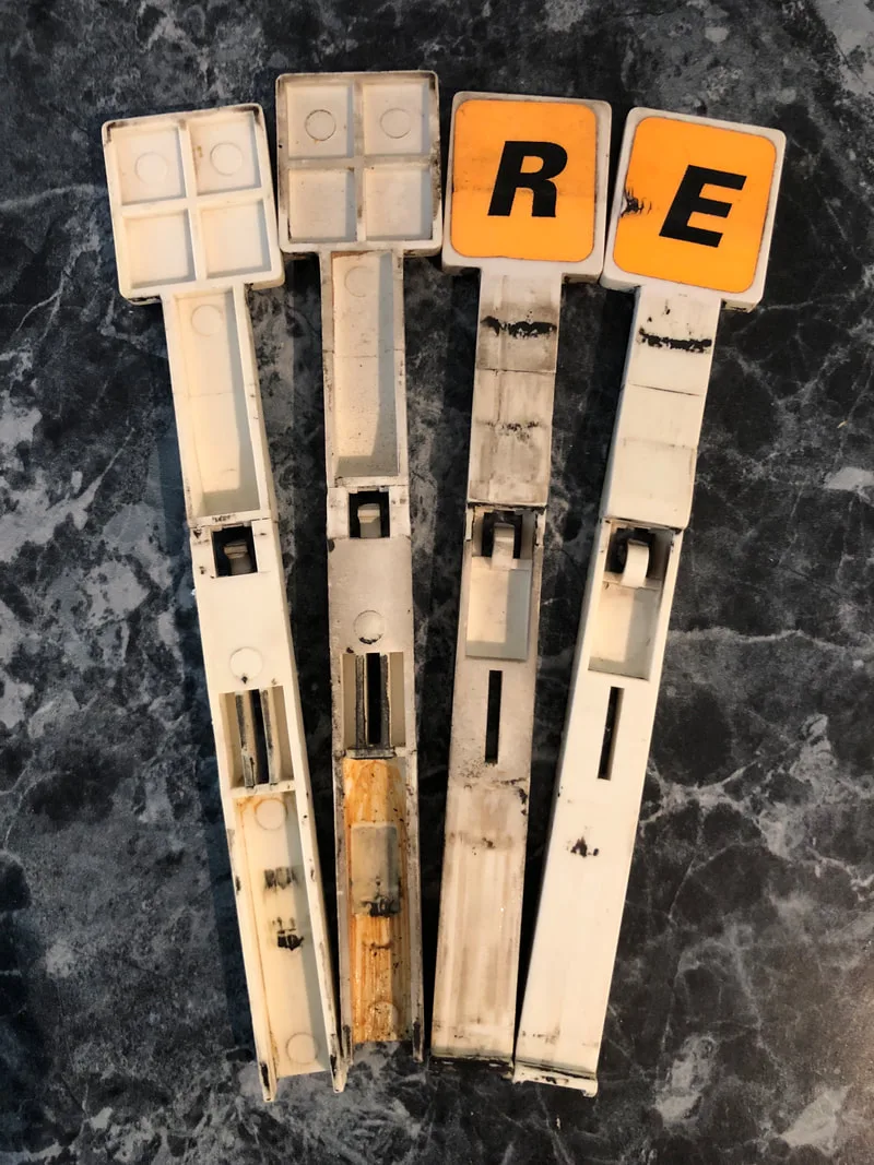
Drop targets before cleaning (2 inner targets) and after cleaning (2 outer targets).

The cleaning had a marginal effect. The targets moved more quickly and seemed to 'snap' down and up more easily, but the 'A' target still did not drop fully.
Keep in mind that Data East drop target assemblies from the early 90s use leaf switches to register a dropped target, as opposed to optos. There are pros and cons to each design, but this issue was directly related to a con of using leaf switches in this kind of assembly. Like the targets themselves, the leaf switch blades had been fouled up, possibly with some kind of grease or other lubricant, which had gummed up and solidified over time. This made the leaf blade sticky, which dragged on the target as it dropped, causing it to stop before it had gone through its full range of motion. This is what was causing the 'A' target to stop midway down. A good clean of the switch blades got them back to their original snappy operation again.
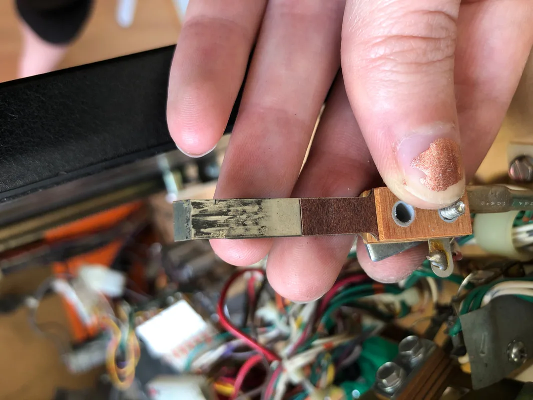
Sticky drop target switch prior to cleaning.

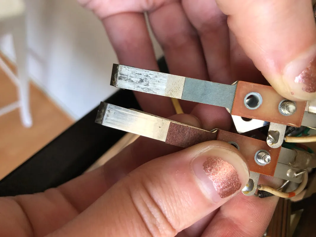
Drop target switches after cleaning (they look dirty but they are just tarnished).

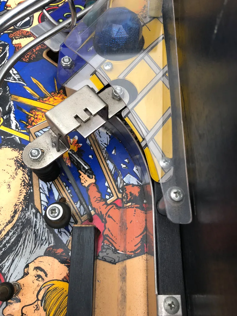
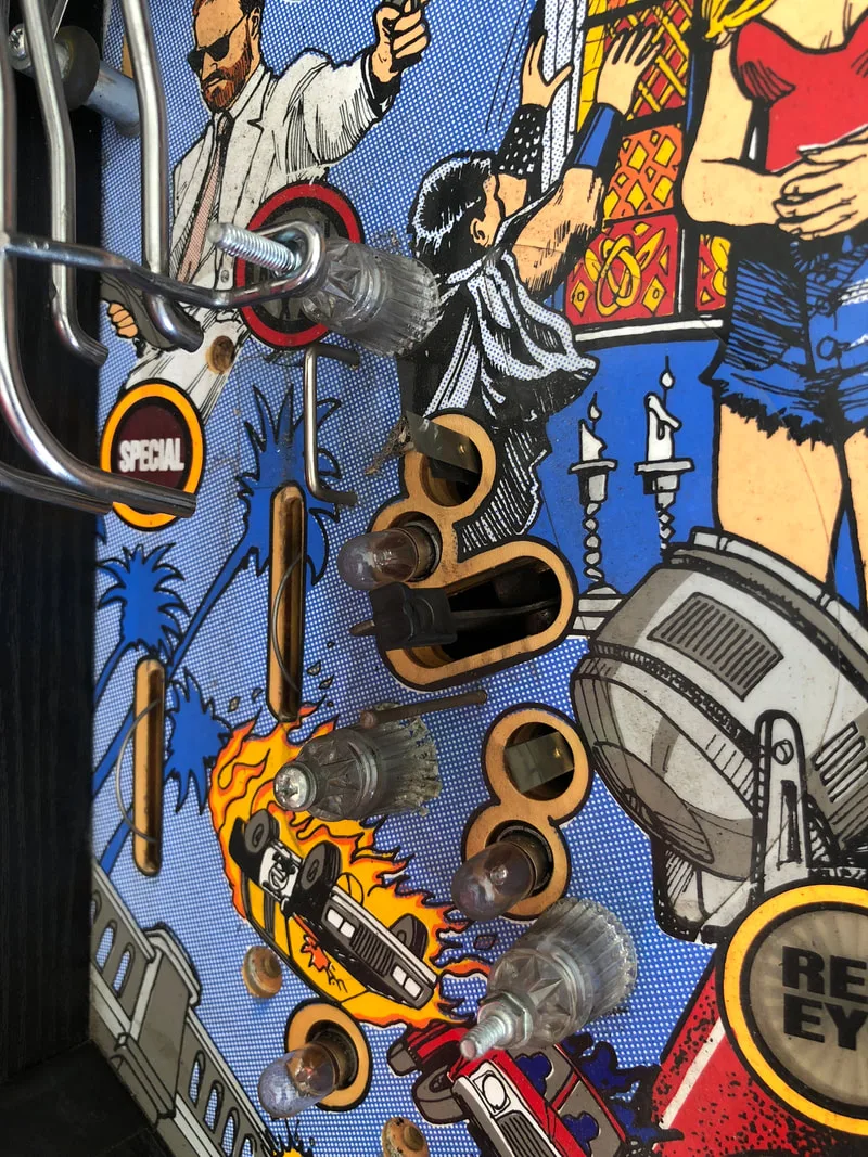
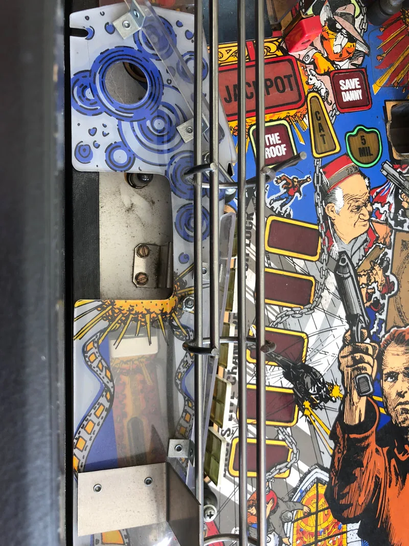
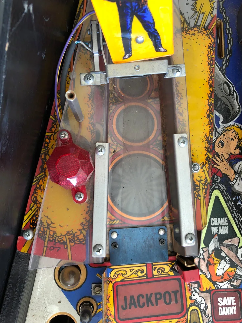
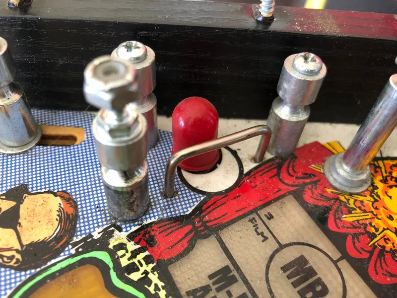
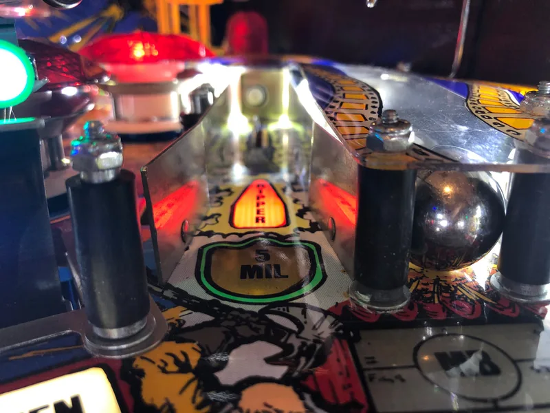
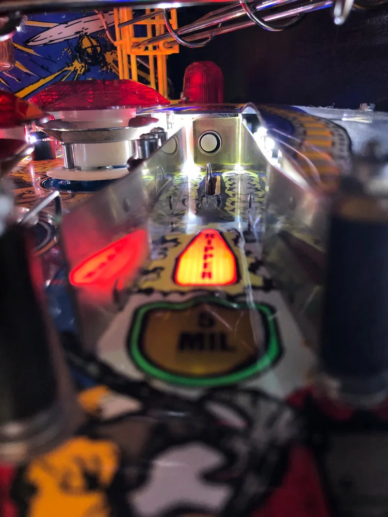
Whenever installing a post into a pilot hole such as this, it always helps to drill into the playfield with a drill bit slightly smaller than the post's thread. That way, the post won't tilt or skew when screwed into the playfield wood.
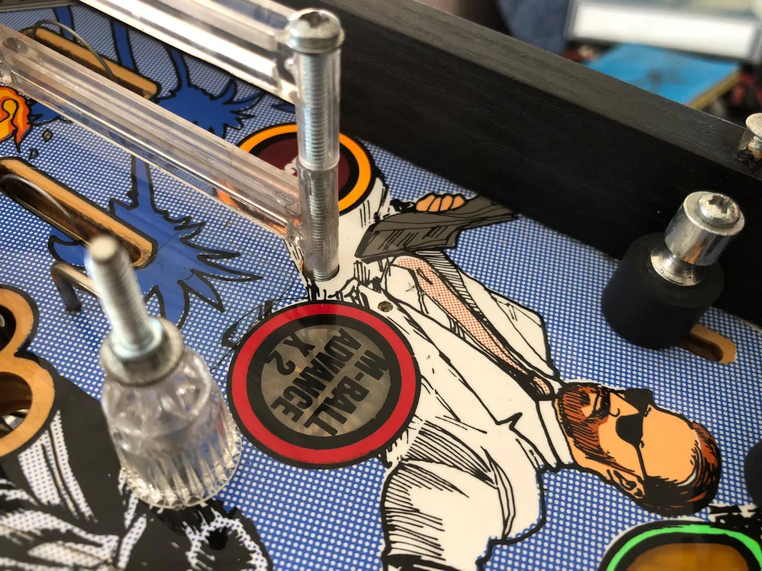
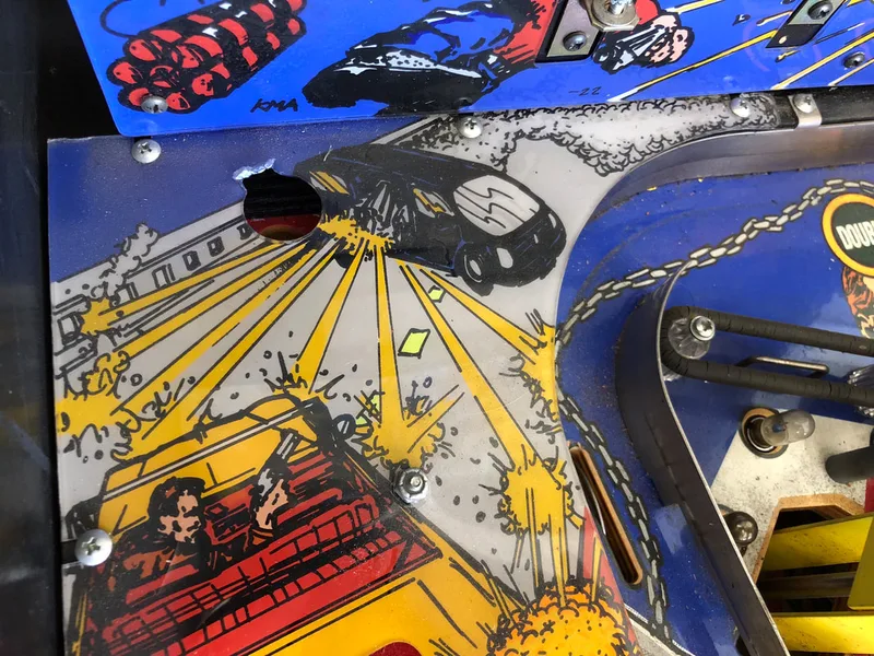
Pilot hole in playfield above left outlane.

Metal post installed.


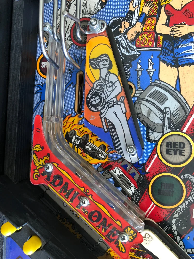
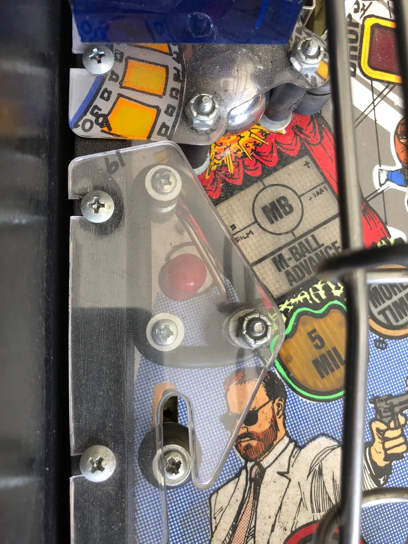
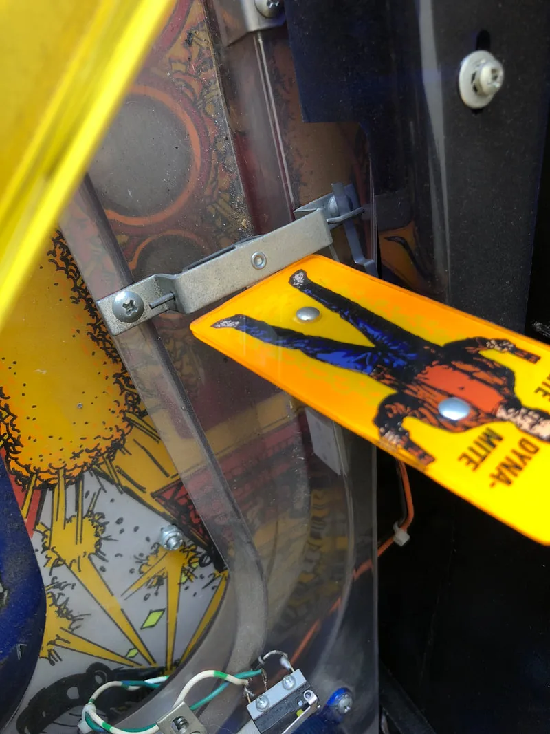
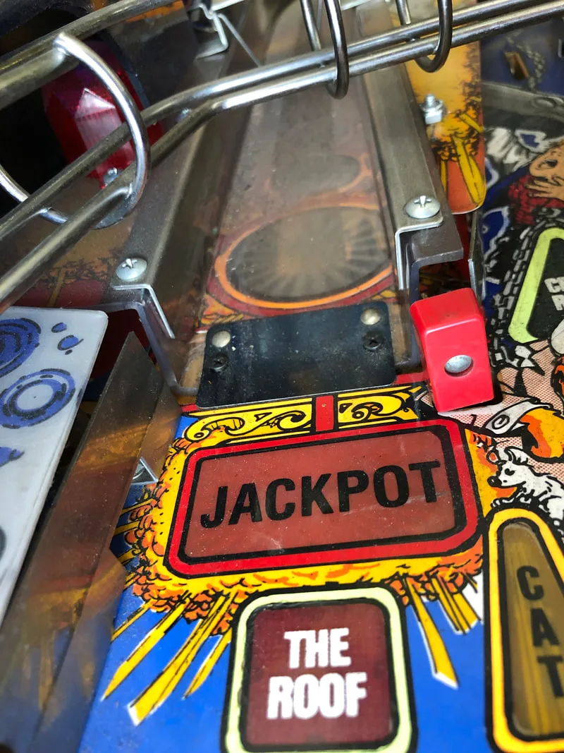
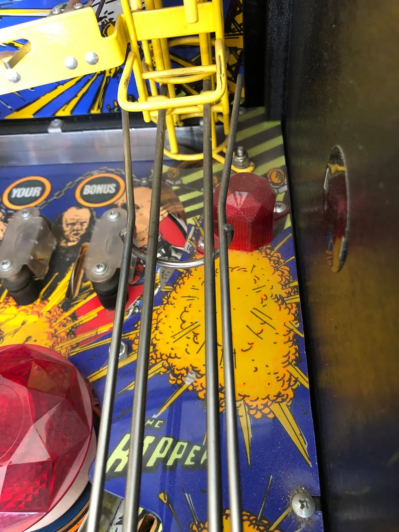
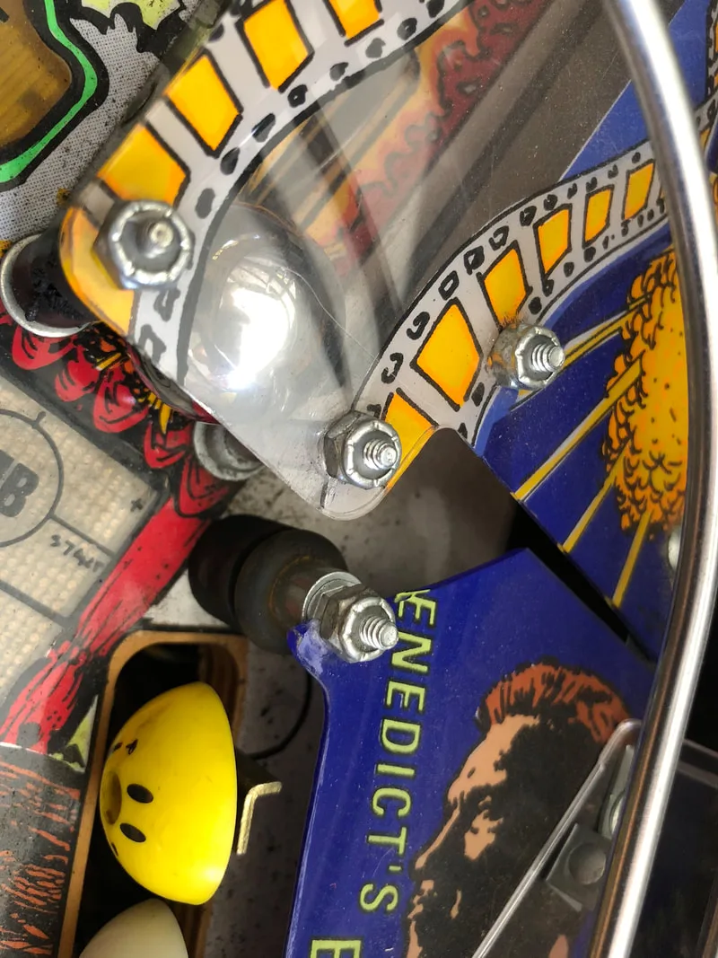
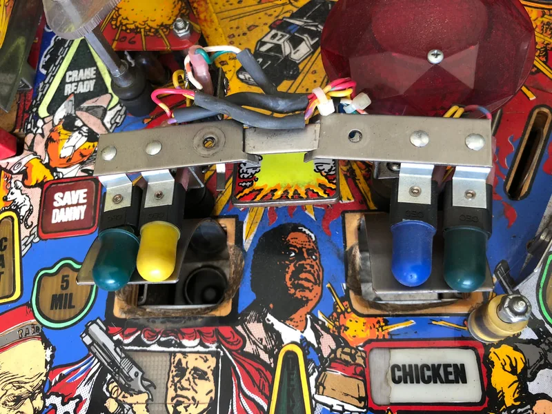
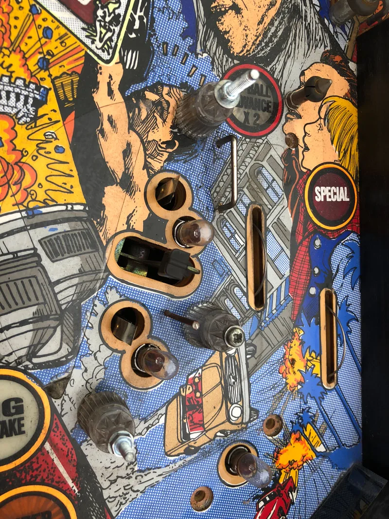
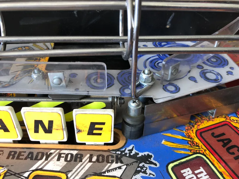
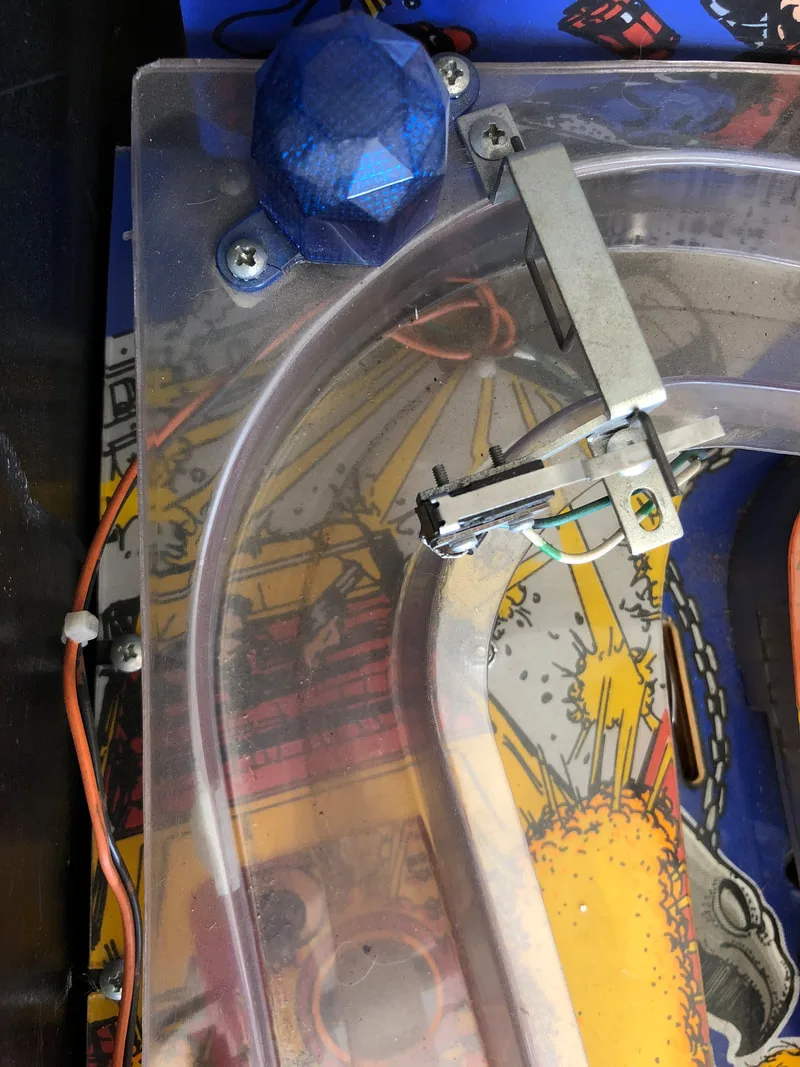
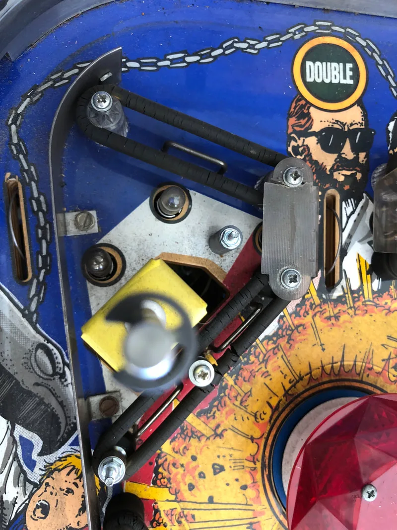
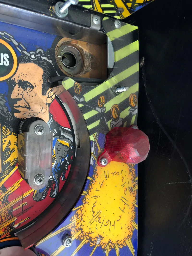
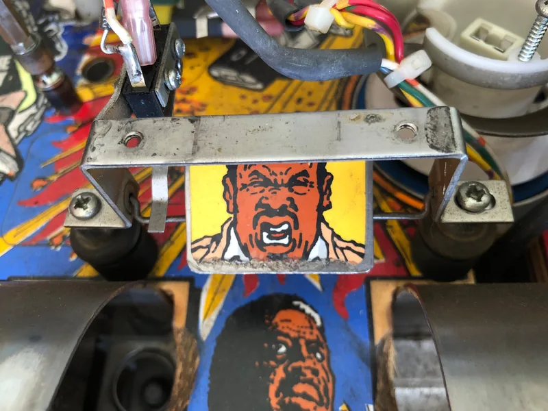
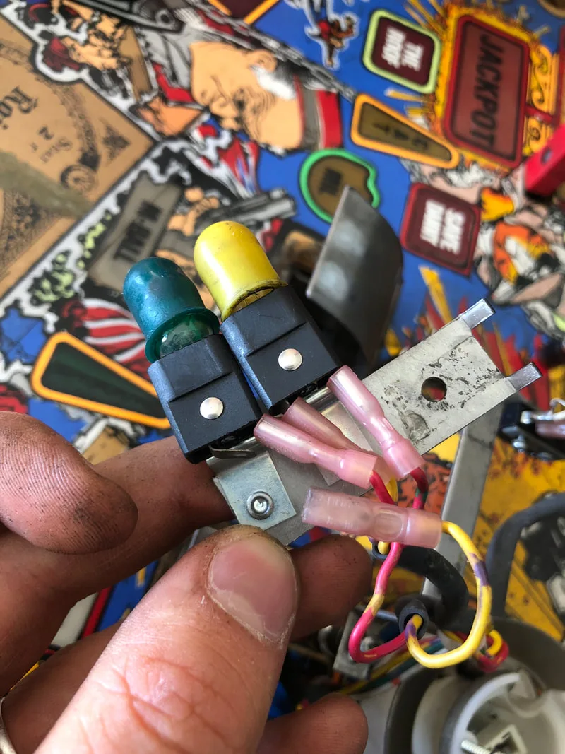
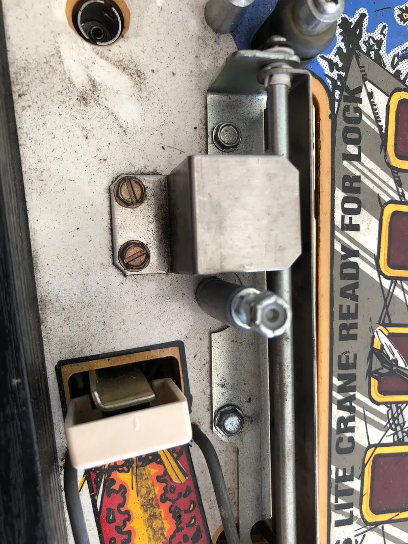
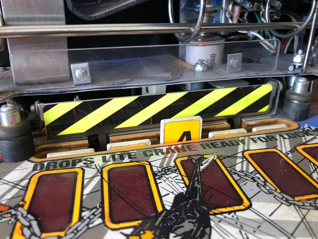
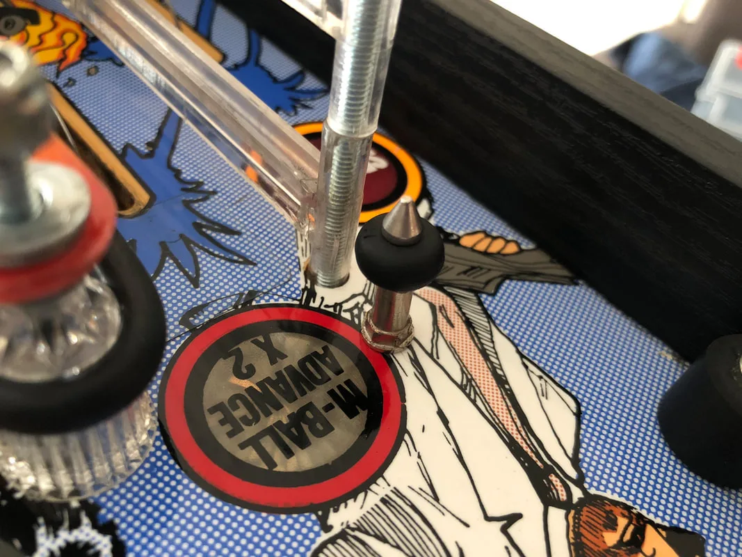
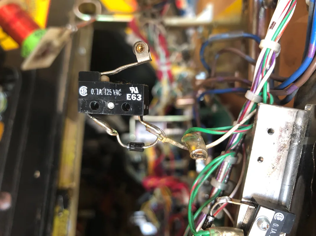
Incorrect switch placement adjacent to the flasher.

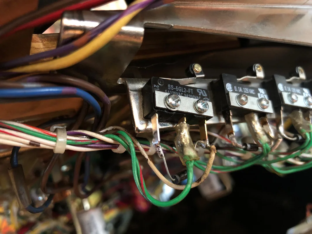
Switch moved to the original position, further from the flasher.
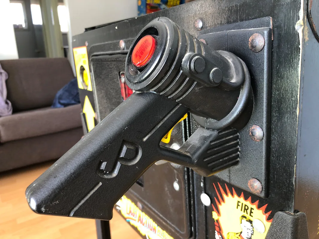
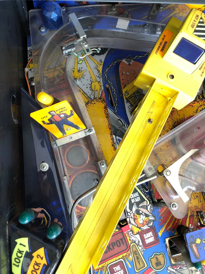
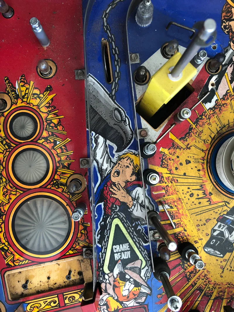
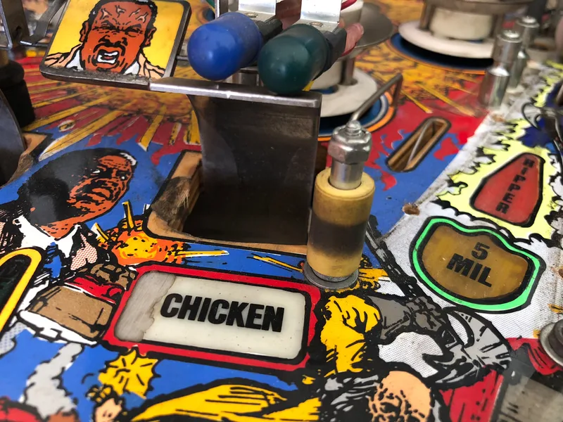
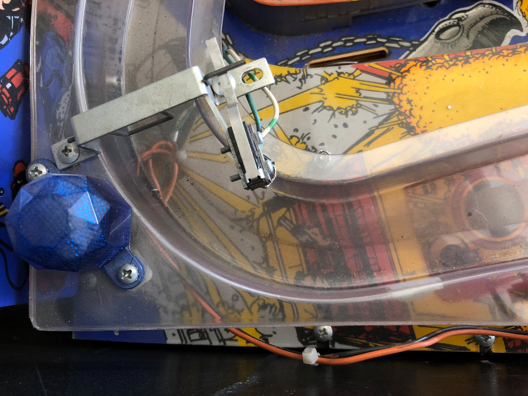
Jurassic Park gun handle fitted on this Last Action Hero. Blasphemy!

Old switch with broken centre lug (green wires).
New switch installed and soldered.
Original screw with a missing head attached to the up-kicker assembly.
New screw installed and switch tightly secured.

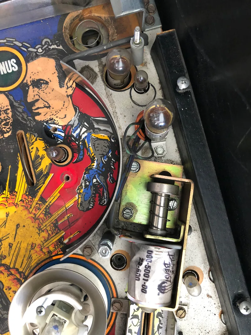
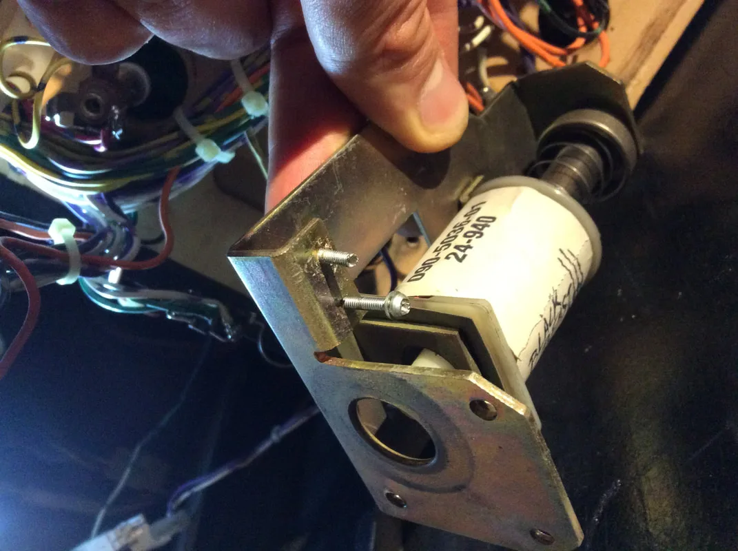
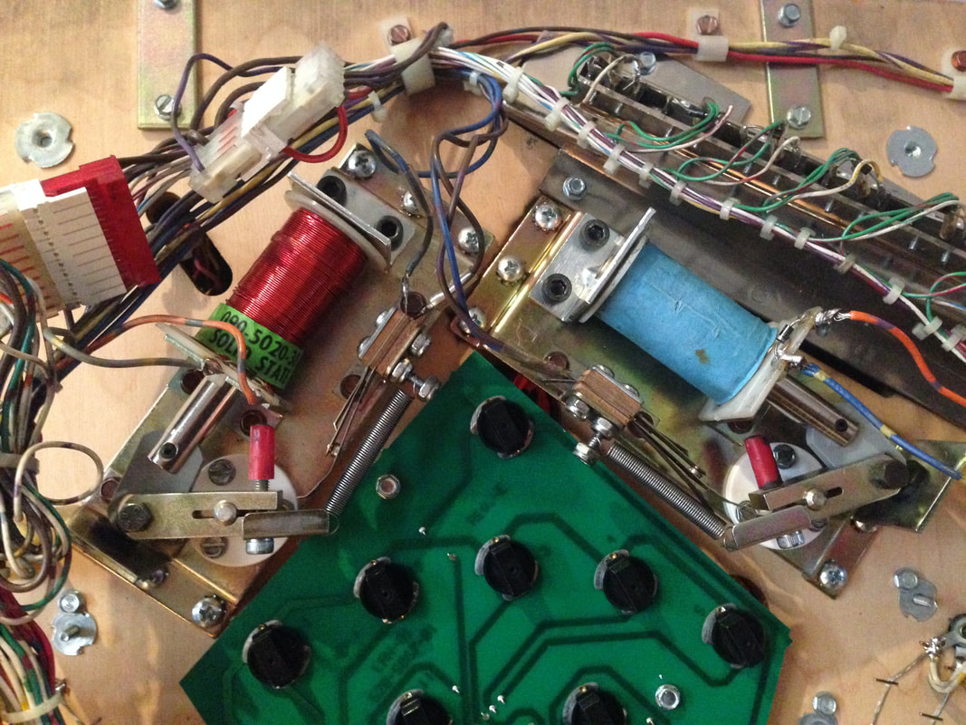
The coil strength settings were set to normal in the adjustments menu, so I had a look under the playfield to see what the flipper assemblies were like.

Incorrect coil (too large) installed on the right flipper assembly.
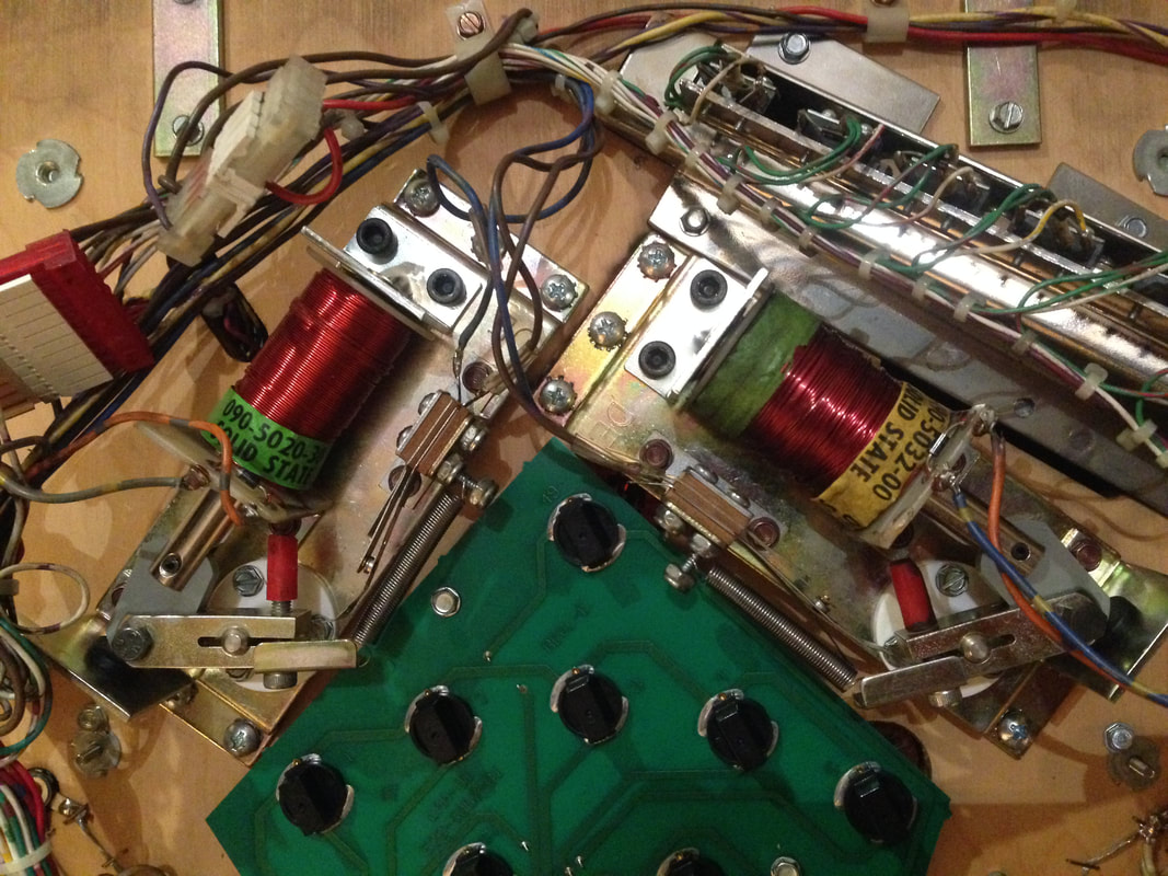
Both of the flipper coils are supposed to be the same, but the one of the right was much larger than the one of the left. A larger coil means more power (generally), and that was definitely the case here. Luckily, I had a spare coil which was the correct replacement (part no. 090-5020-30). When replacing a coil, always check that both the part number and resistance of the new coil matches what is expected. Once I swapped the correct coil in, the flipper's power was reduced and was on par with the left flipper.

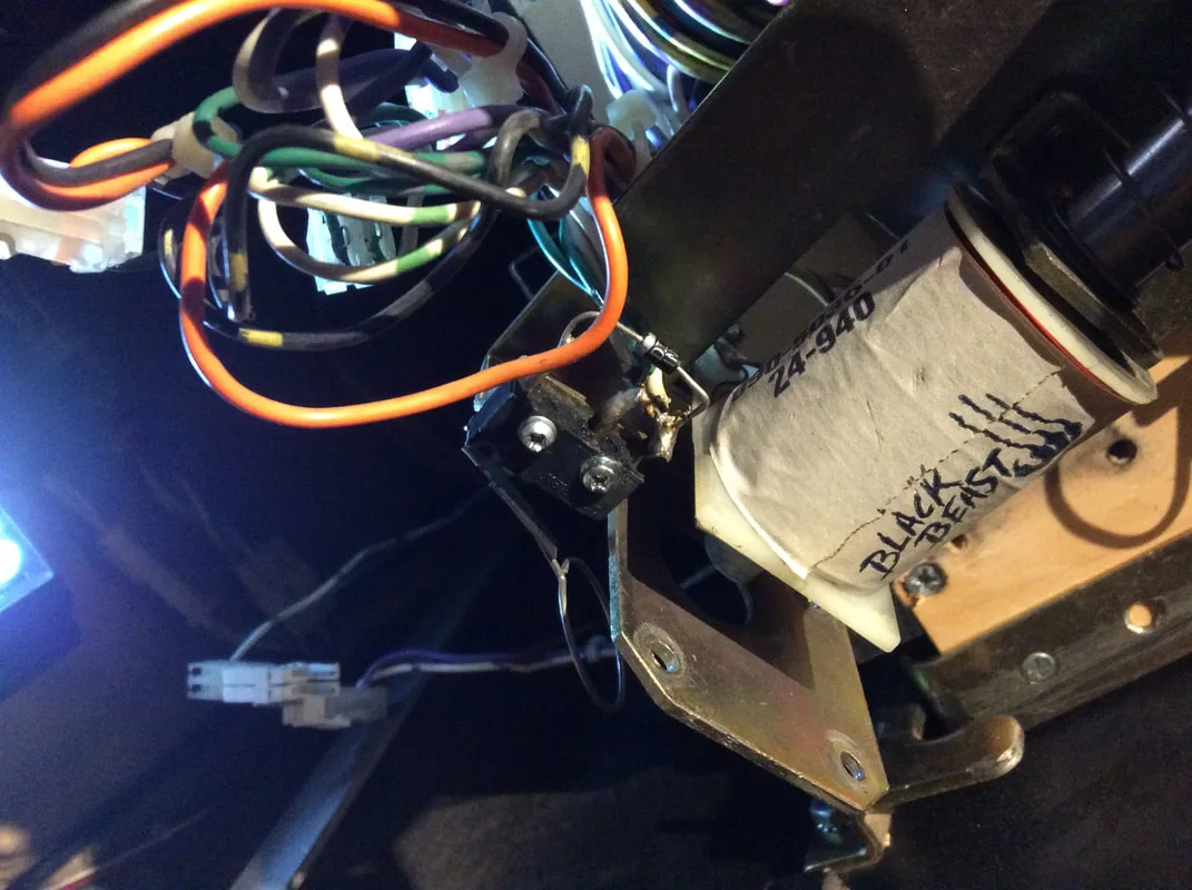
Correctly sized flipper coil installed.

Fixing lamps in place in sockets with hot glue.
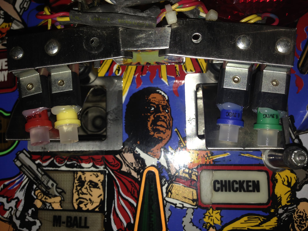

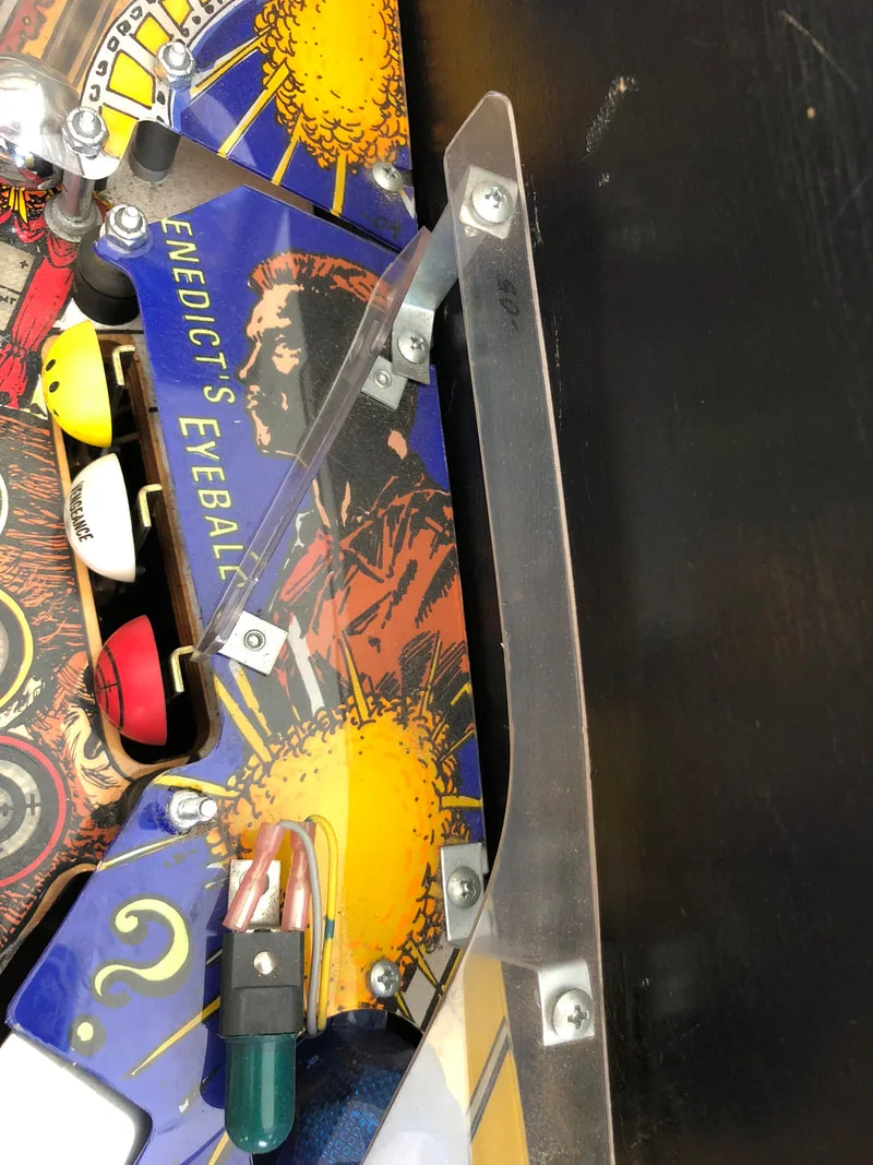
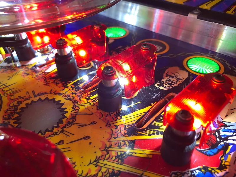
Original clear lane guides.

New red lane guides installed.
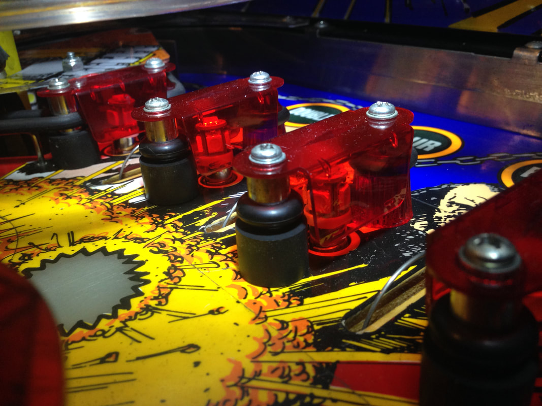
New red lane guides installed and lit up.


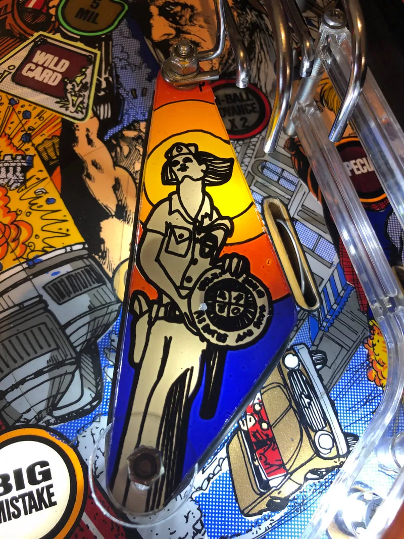
Playfield wear on the Golden Ticket area.
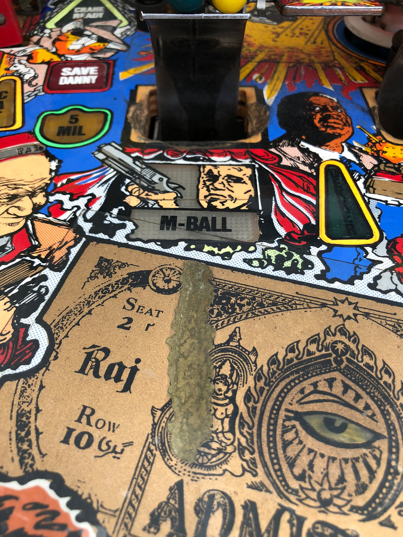
The wear on this Last Action Hero was pretty extensive, but had been covered up by someone previously. They had used gold paint to seal the worn area and had covered the entire patch with mylar. All in all, not a bad repair attempt. While the gold paint stands out, it's much better than leaving it bare, and the mylar will ensure it stays in good condition. As this customer did not want the playfield fully restored, repairing this area to look like new was not necessary. However, there is an easy way to do it. Pinside user atariaction has created a ticket decal which is designed to cover up the entire Golden Ticket on the playfield. Plus, the new ticket overlay is actually more detailed and colourful, and better matches the ticket which is depicted in the film. I usually don't like overlays as a method of playfield repair, but in this case, it's not a bad option at all. So, if you're in need of a new ticket, send him a message on Pinside!
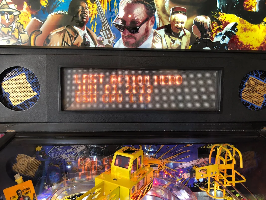
Loading screen showing the updated ROM version.
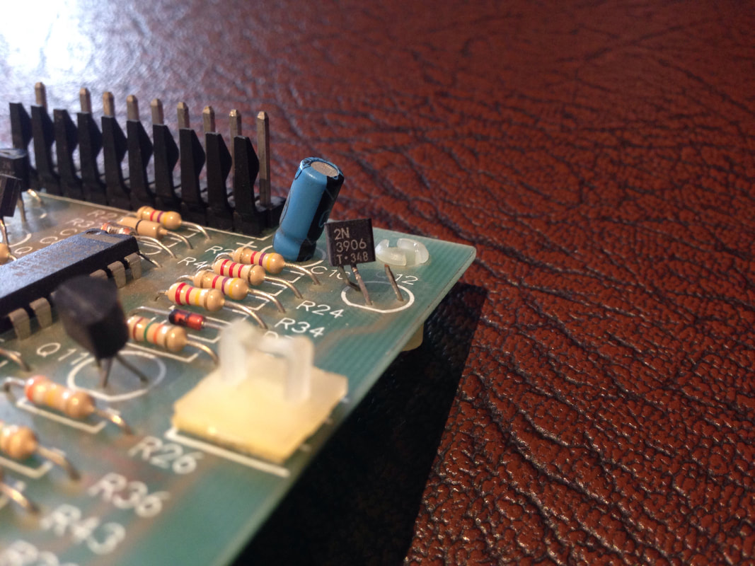
Power is sent to Data East flippers via the flipper board mounted to the left wall of the cabinet. So, I inspected it for any issues. The fuse holders on these boards are commonly broken or damaged, but they were fine in this case. The transistors also seemed OK, for the most part. I only discovered the issue when I started to touch each of the components to make sure they were securely soldered to the board. The transistor at Q12 was soldered to the board, but one of the transistor's legs wasn't secured to the body of the transistor. Q12 is in the flipper hold power circuit, which sends 9 volts to the flippers after the initial 50 volt power stroke. Without this transistor, there was no hold voltage. I didn't have any spare 2N3906 transistors in my tool box, but luckily, Jaycar sells them. After installing a new transistor, the flippers held themselves up as expected.

Broken transistor at Q12 of flipper board.
There's not much to reassembly of Last Action Hero; the playfield is quite simple once you take the ramps and wireforms off. The trickiest part is reconnecting the crane and routing the wires through the playfield properly; make sure they don't bind when the crane moves. There are also some wires that connect to the spinner switch and lamps above the left and centre scoops. Make sure these wires don't interfere with the spinner when it rotates. Other than that, use your disassembly photos to put everything back in place!
All of the rubber rings were replaced on this playfield. The manual specifies that you need 19 post rubbers (part no. 545-5151-00), but you actually need a few more than that (about 5 from memory). The rubber list in the manual is wrong on a couple of other sizes, so get a couple of extras of each size to cover every possibility.
Last Action Hero lamps under the playfield are mostly easily accessible, so swapping them over to LEDs is easy. I didn't develop an LED kit for this machine as I simply used white all over the playfield. This worked well and the inserts lit up nicely. The general illumination was made up of 5 LED lamps which threw a lot of light around. There are a lot of flashers on Last Action Hero - don't forget the four flashers under the mini domes on top of the playfield, too! The backbox was fitted with frosted white LEDs.
To top everything off, there are some nice custom instruction cards available for Last Action Hero available on Pinball Cards.
Conclusion
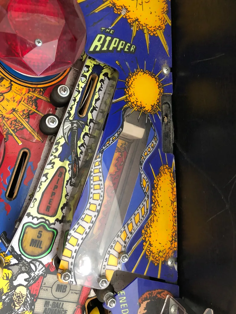
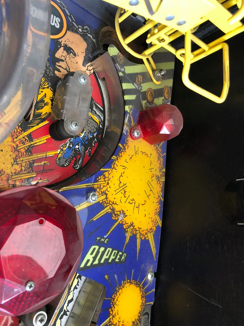
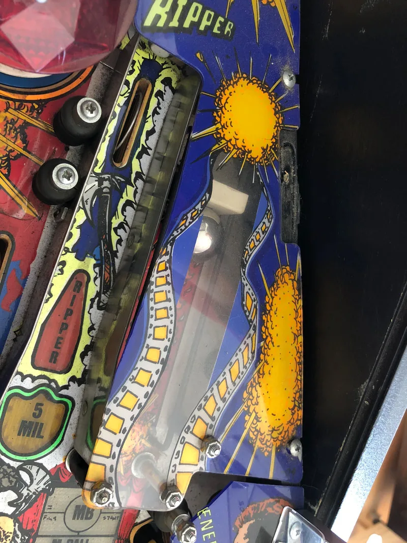
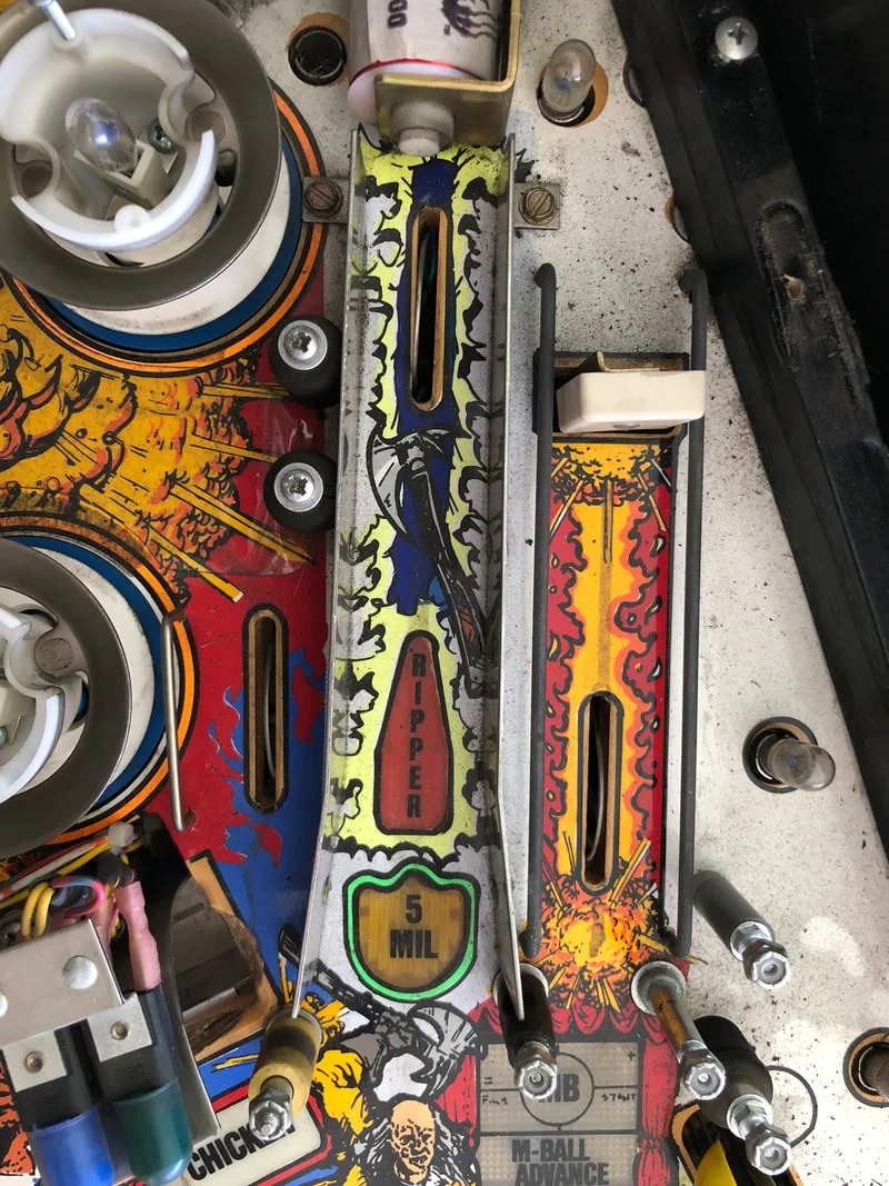
Last Action Hero is a fun game. When all of the playfield magnets are working properly, multiball is a hell of a lot of fun. Data East was really throwing a lot into their games at this point. Last Action Hero is a heavily mode-based game, so you have to have good accuracy to do well. There are plenty of cool features, too. I love kickbacks that send the ball back to the flippers. The Ripper on Last Action Hero does just that, and reminds me a lot of the Yagov kicker on F-14 Tomcat (Williams, 1989). The crane is one of my favourite ball lock toys ever. I love playfield gadgets that physically move the ball from one place to another and the crane probably moves the ball over a greater distance than most other playfield gadgets in pinball. The shot geometry on Last Action Hero is really satisfying. Nailing the ramp combo shots, or sending a ball to the crane upkicker are both fun shots to do. The playfield is not too cluttered, so some looking for a really deep and complex game may not be entertained for too long, but it has that classic "one more game" feel that a lot of early 90s games nailed perfectly.
The restoration, while it took a long time and was frustrating at times (i.e. dealing with the magnets), was worth it to get this game back to its former glory. The customer was very happy with the result, and noted how all of the shots were so smooth and everything on the playfield worked as it should have. I'd be keen to add a Data East machine to my collection sometime, and Last Action Hero would definitely be near the top of that list.
Unfortunately I cannot remember the size. But yes, it is an Allen key.
I found plenty of other useful information here too though... thanks.
p.s. there is a new version eprom the 1.13 with extra.s, also the display ic need, but more play and talk :)