- Published on
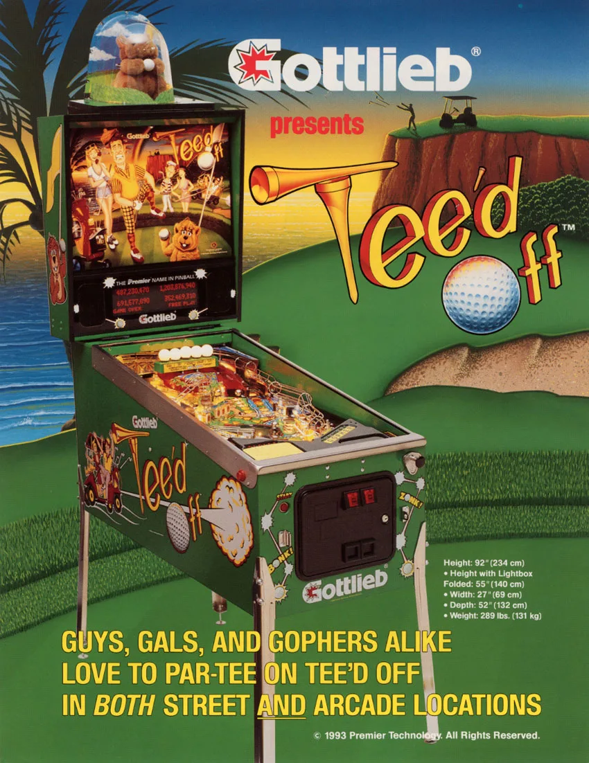
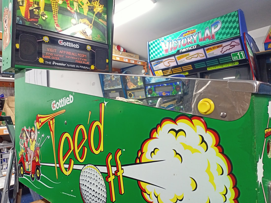
Tee'd Off
- Author
-
-
- Name
- Posts
- Posts
-
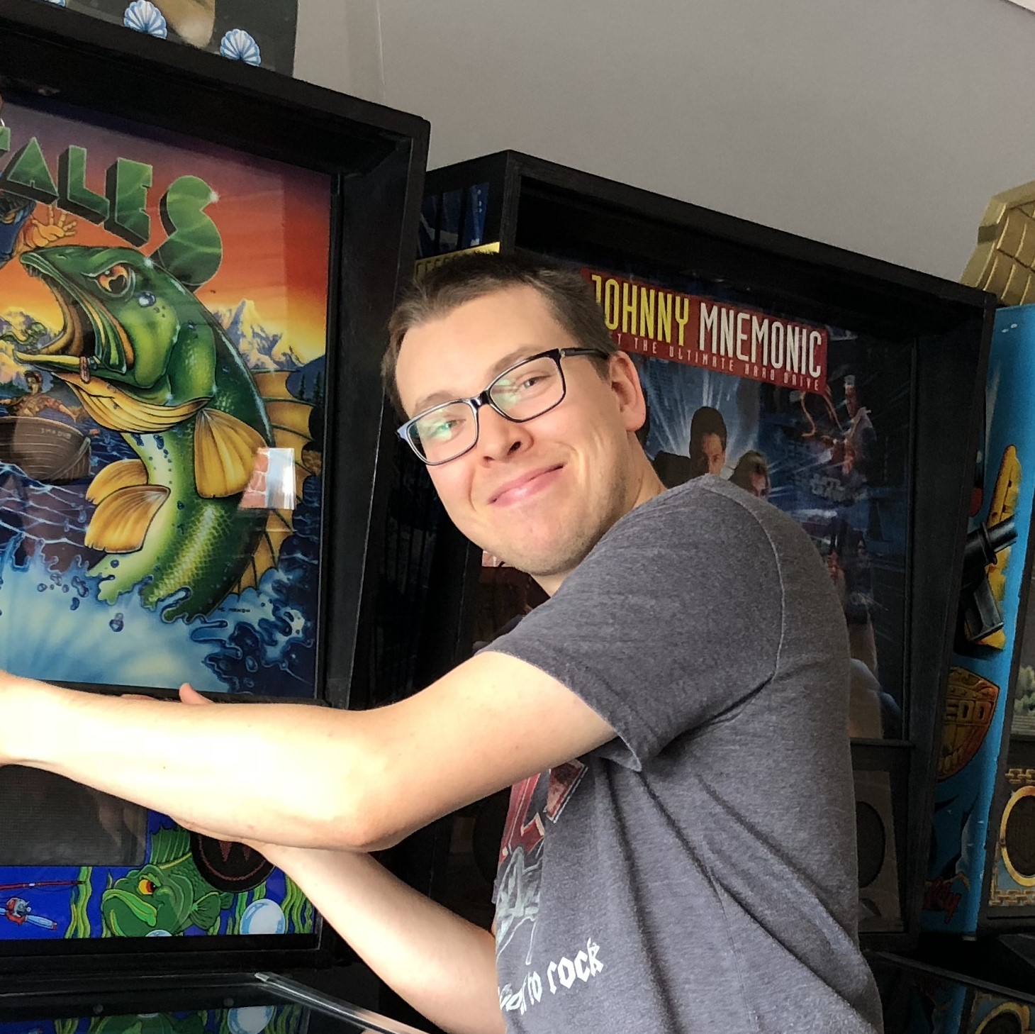
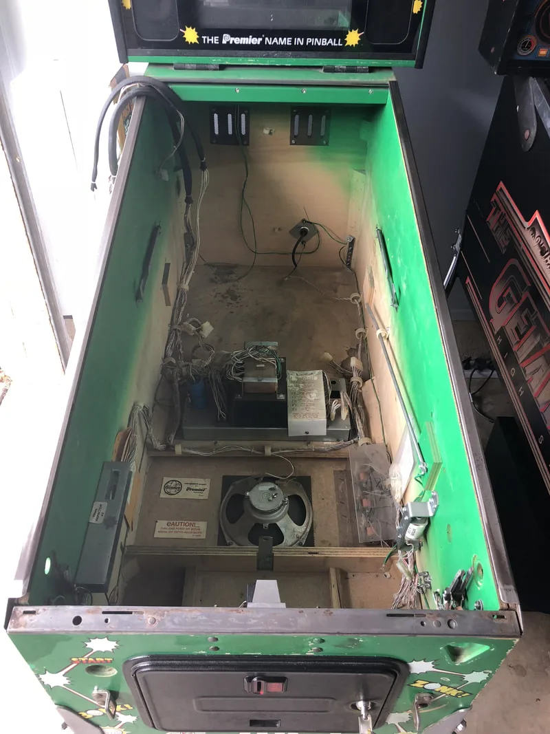
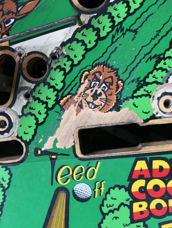
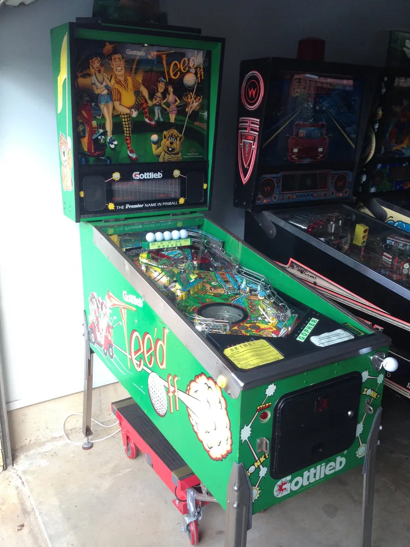
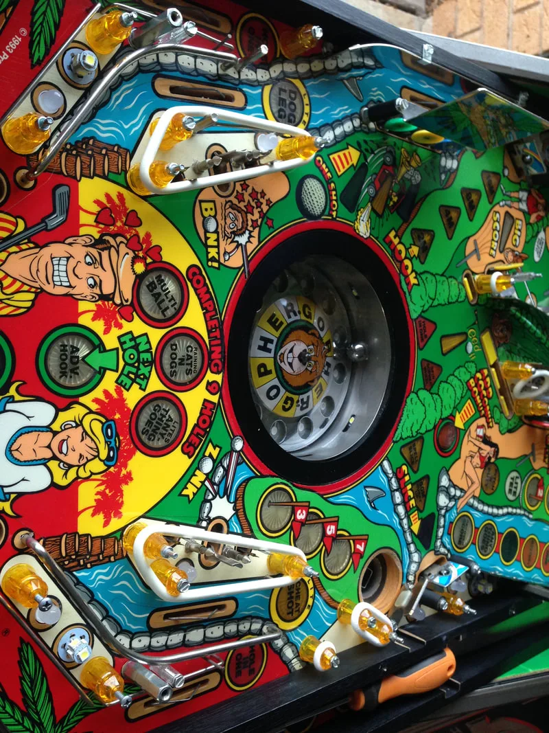
Up until this point I had spent almost all of my time restoring Bally and Williams games. I was comfortable enough with doing plenty of repairs on those machines, but I was keen to get some more experience working on a game from a different manufacturer. Enter Tee'd Off (Gottlieb, 1993). Gottlieb was one of the major manufacturers during the 1990s so I figured that this machine would be a good point of reference for future Gottlieb DMD game restorations. It would also be interesting to study the differences between how Gottlieb had done things and what I had become so accustomed to over the last several years. However, the greatest challenge with this Tee'd Off was definitely going to be the playfield repair work. There was a lot of wear on this playfield which had worn the playfield artwork away to the point that the playfield wood was showing. So, this was a good opportunity for Fiona to put her painting skills to use as well.
- Timber in good condition. Some small scuffs and marks.
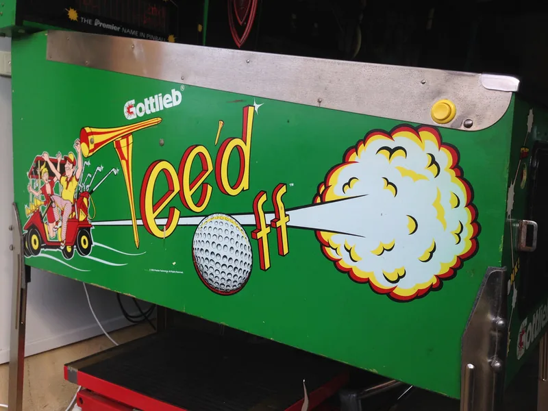
- Side artwork in good condition.
- Translite in good condition.
- Topper in good condition and working.
- Legs in poor condition. Covered in old paint.
- Playfield was very dirty.
- Consumables (rubbers and lamps) dirty and in poor condition.
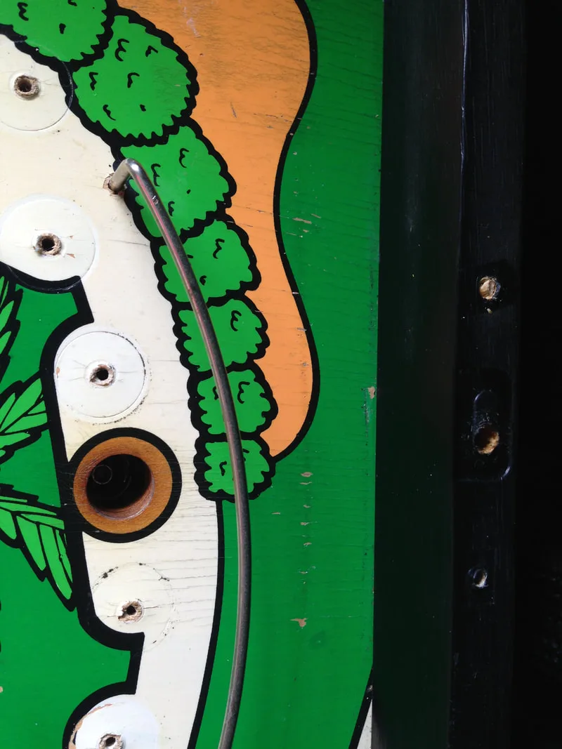
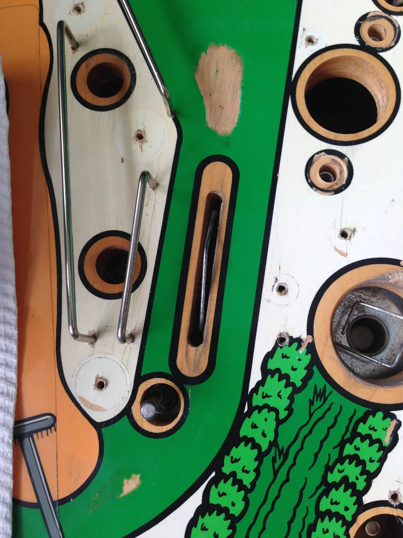
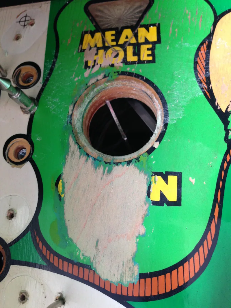
- Playfield artwork significantly worn in some areas.
- Plastics in good condition.
- Playfield mechanisms/toys in good condition.
- All mechanisms and assemblies very dirty.
- Consumables (coil sleeves, flipper parts) dirty and in poor condition.
- Machine booted up and played.
- Visual artefacts on display.
- Playfield and backbox wiring in good condition.
Disassembly
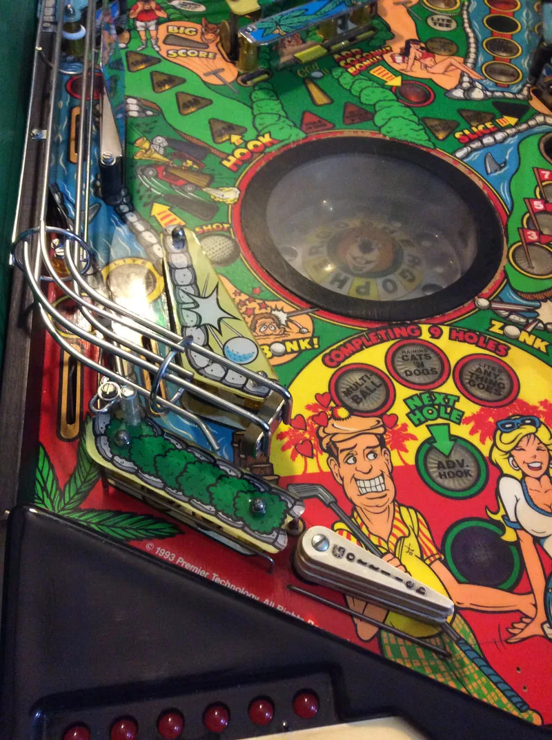
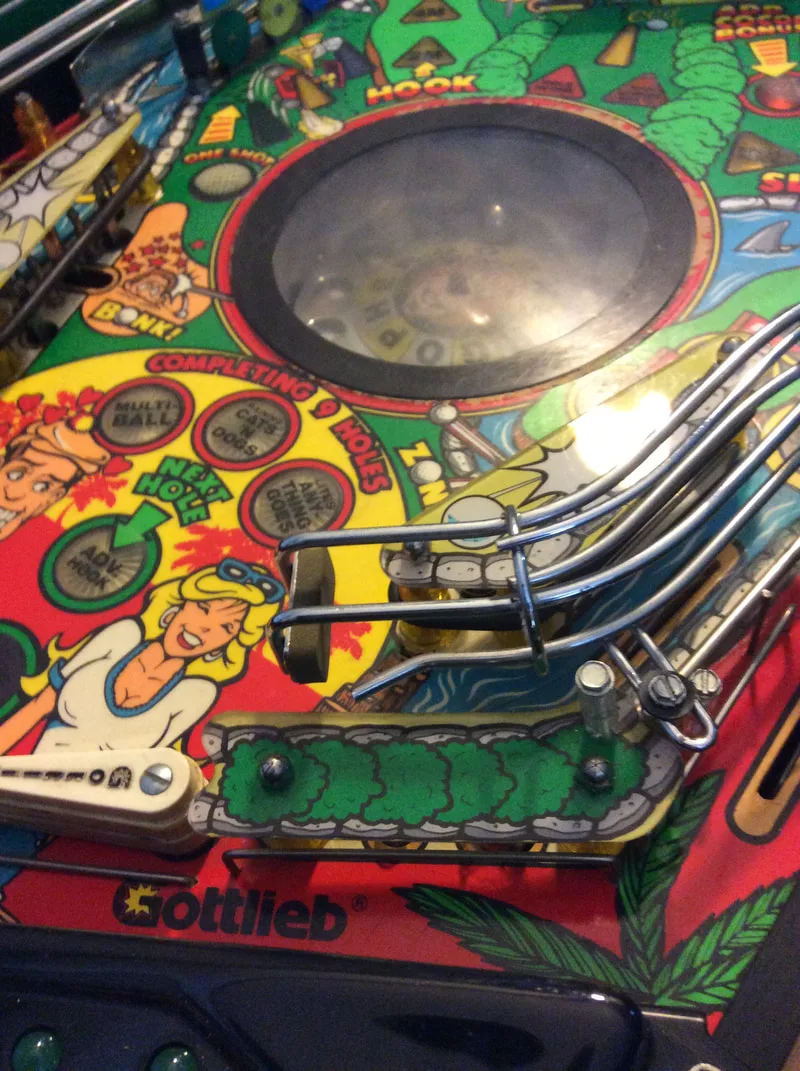
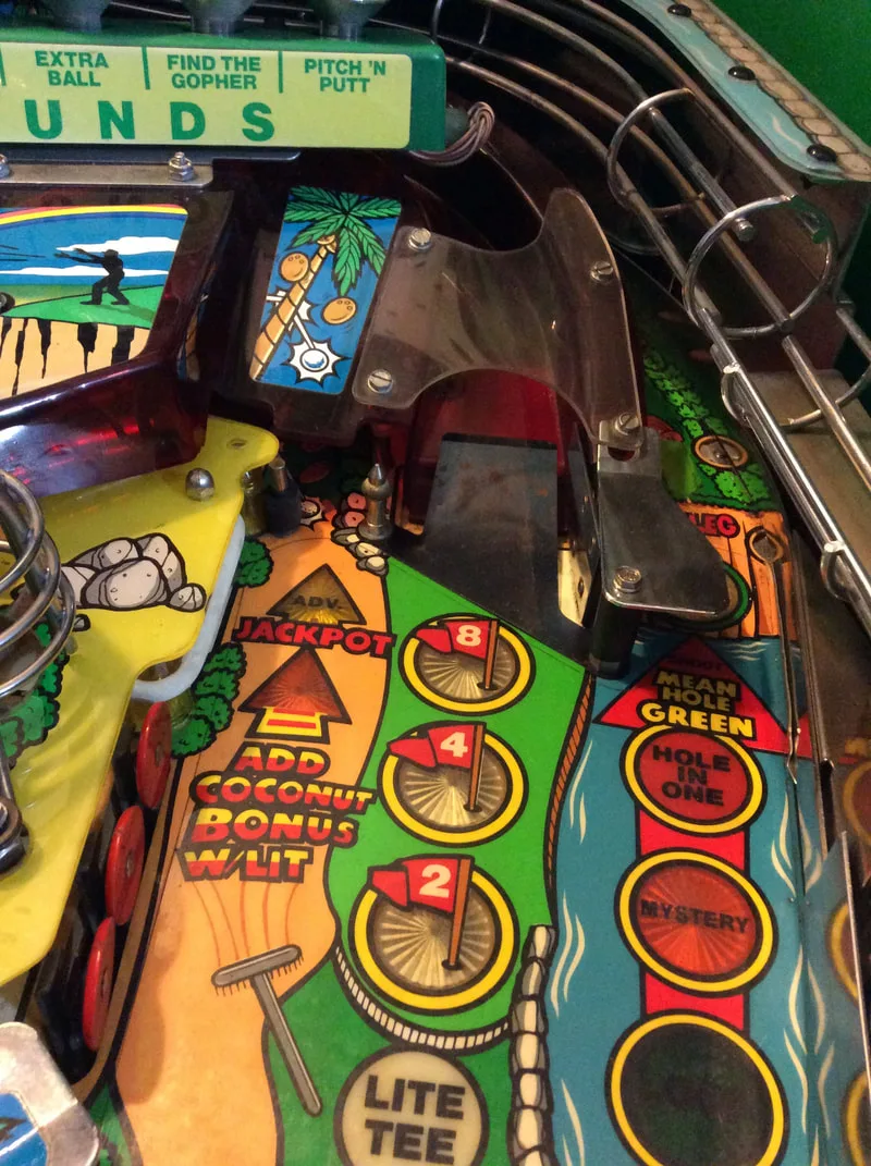
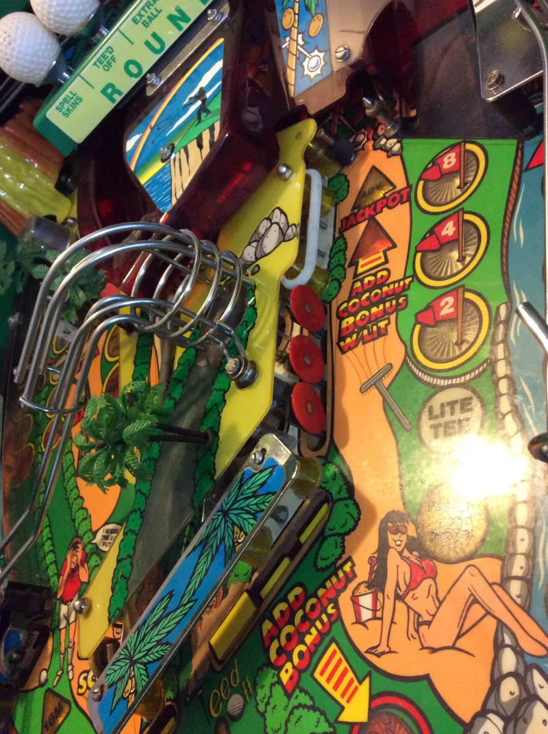
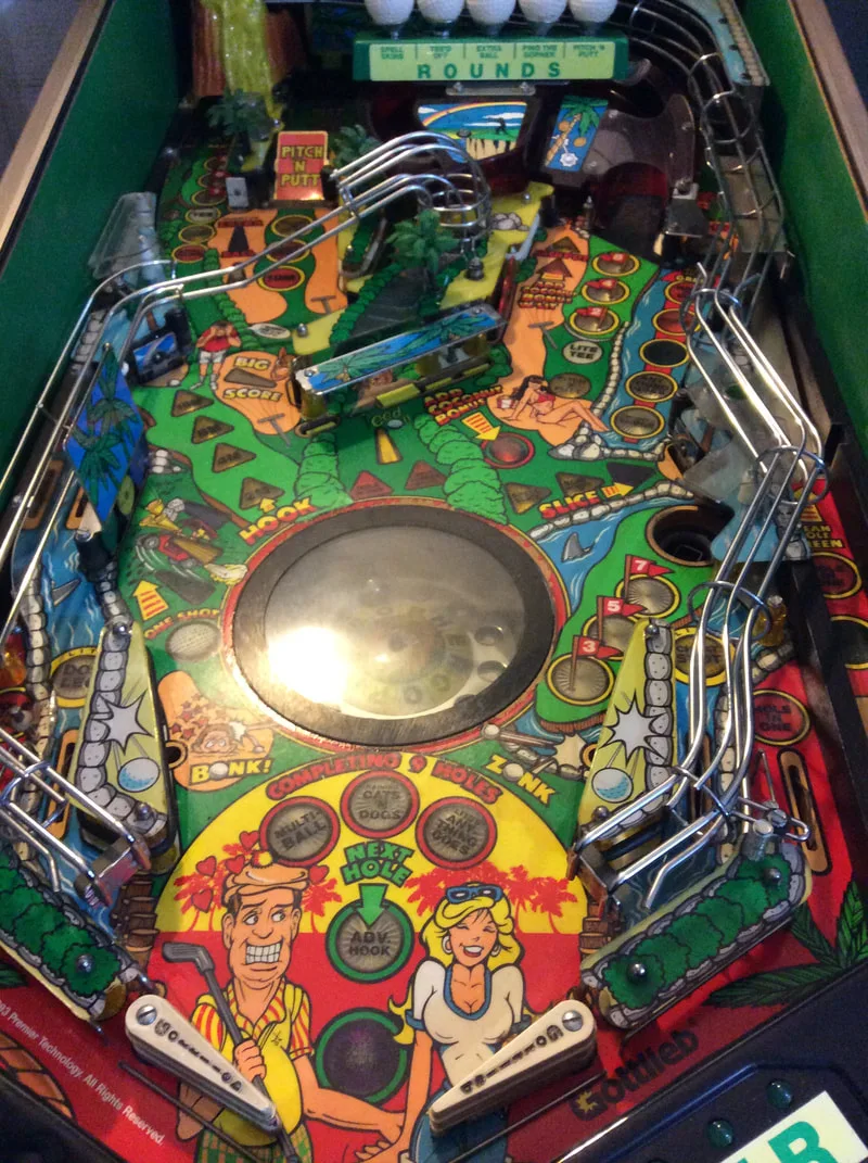
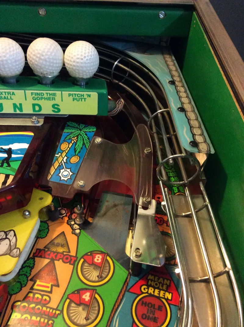
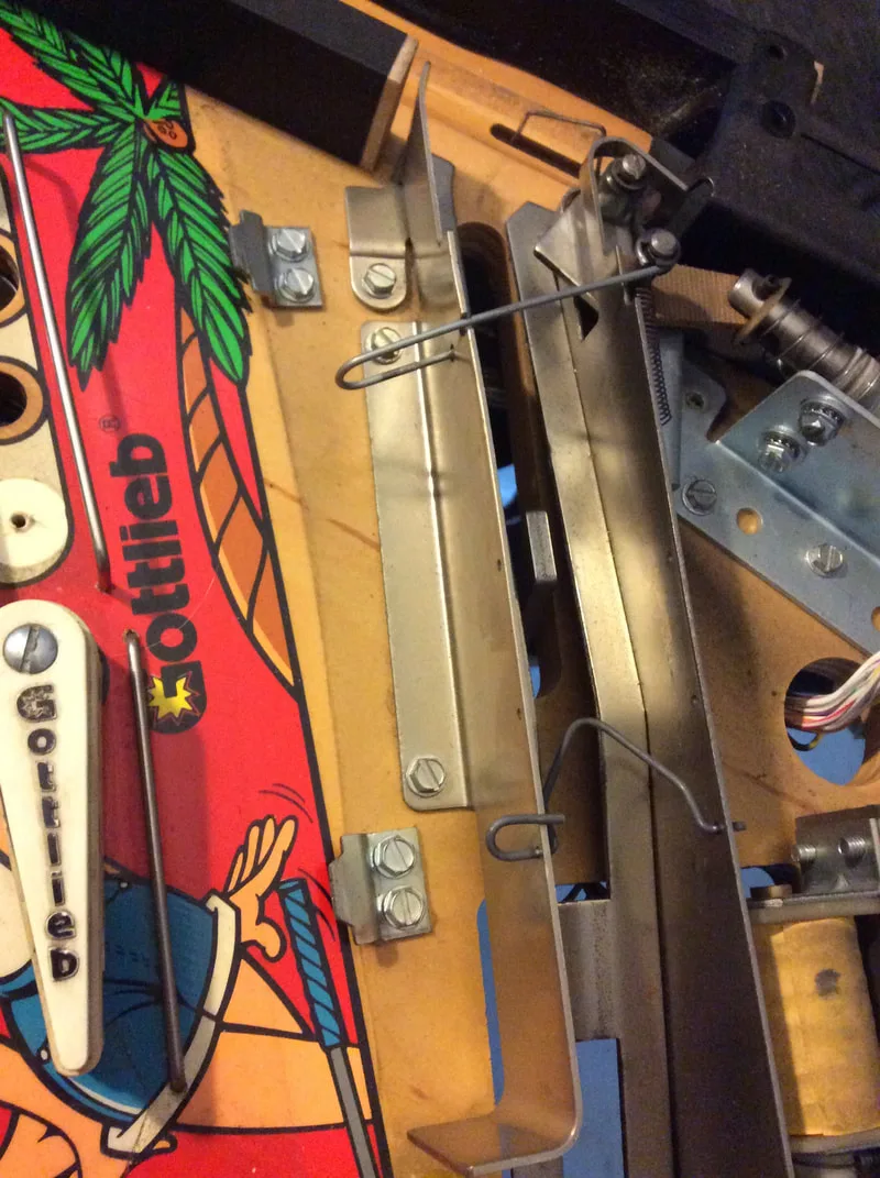
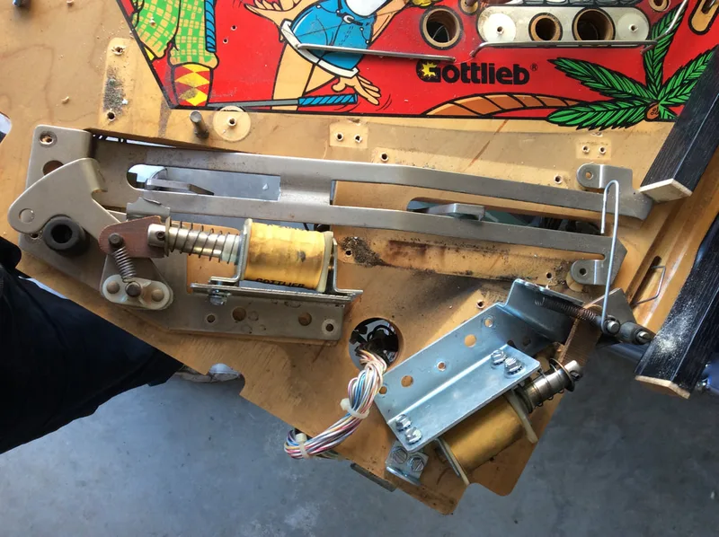
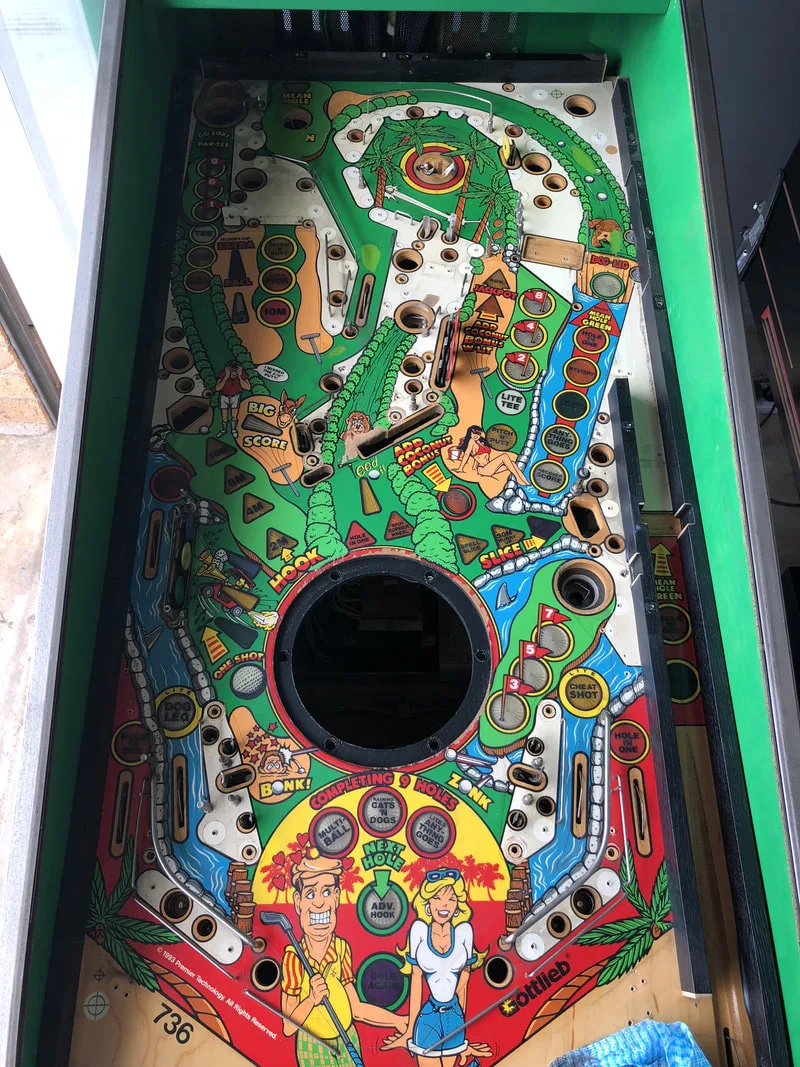
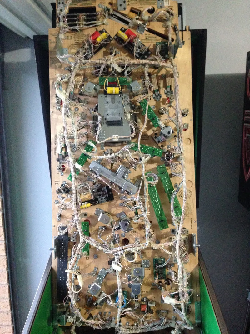
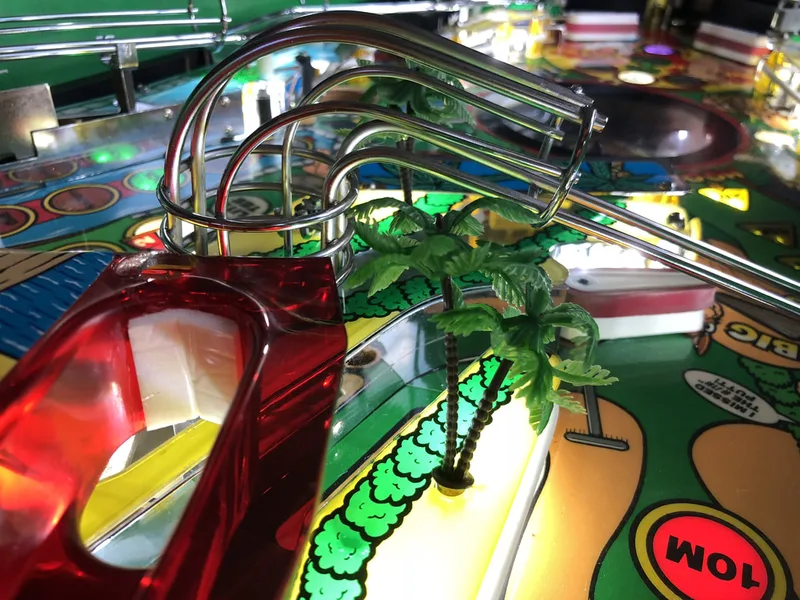
Tee'd Off actually has a very simple playfield with only a couple of wireforms and one main ramp. The rest of the game takes place on a single-level playfield. As always, taking pictures is the key, and remembering where the parts go. Playfield disassembly is pretty routine. Most posts screw into tee nuts under the playfield, which have a habit of being ripped out of the wood when the screws get stuck. This happens often as Gottlieb used Loctite to secure the playfield posts in the nuts. On the other hand, cleaning the underside of the playfield is an absolute breeze as the lamp boards are easily removed using hairpin clips and under-playfield assemblies are clearly marked on the underside of the playfield. Below are some images of disassembly.

After disassembly, the game went through my standard restoration process to get it playing and looking like new. During the restoration process, I dealt with a number of issues, described below.
Tips & Troubleshooting (click on sections below to view details)
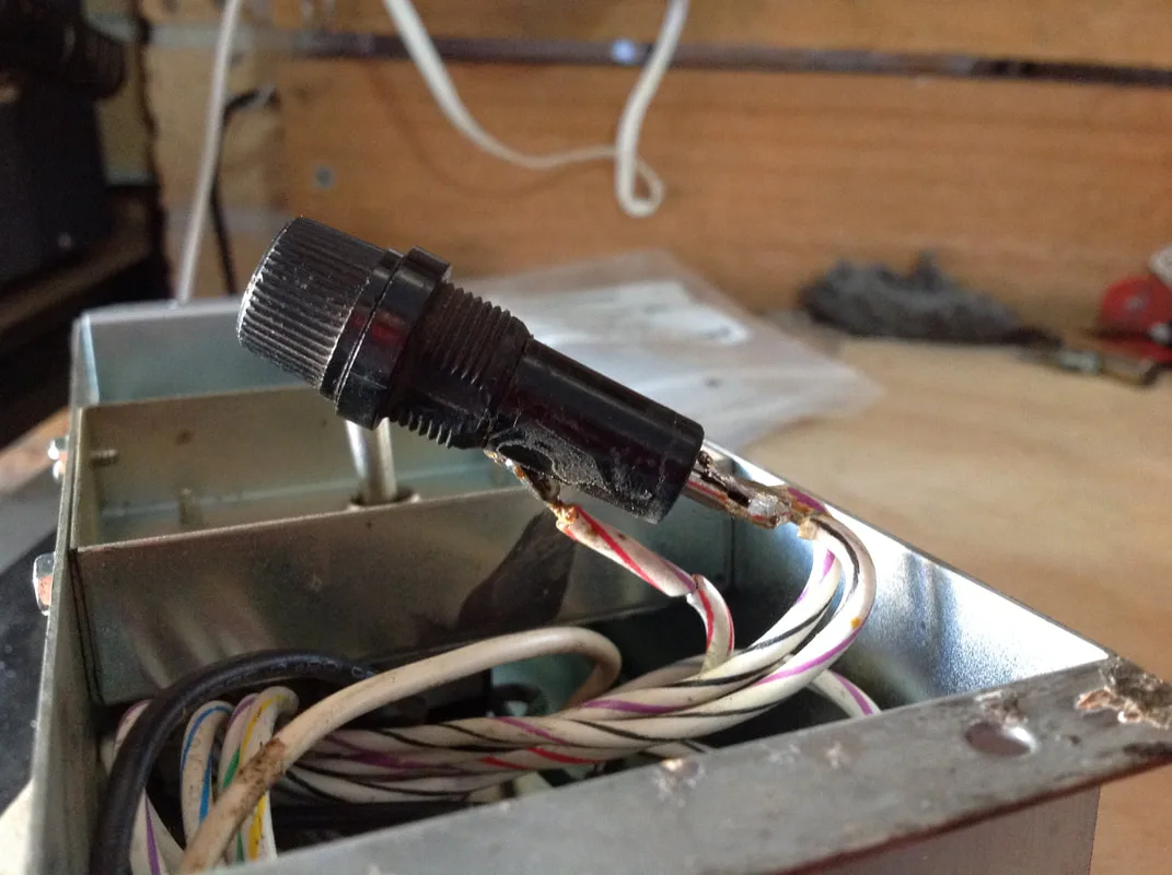
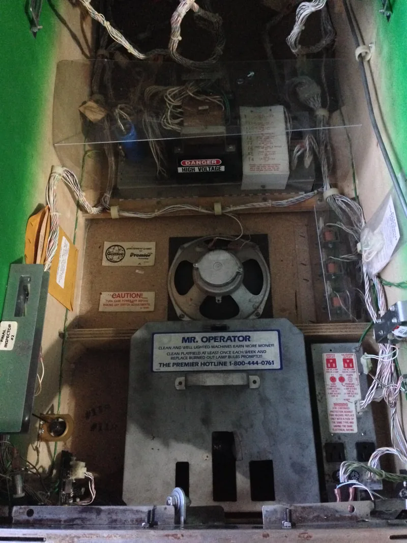
Incorrect size fuse holder, which was trucked away inside the power module.

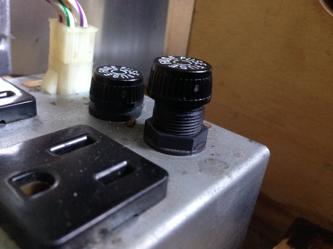
Better fitting fuse holder installed.

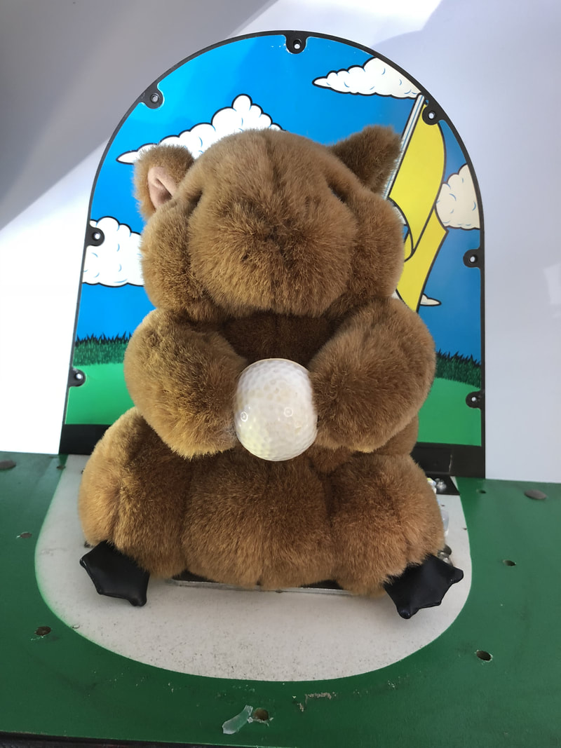
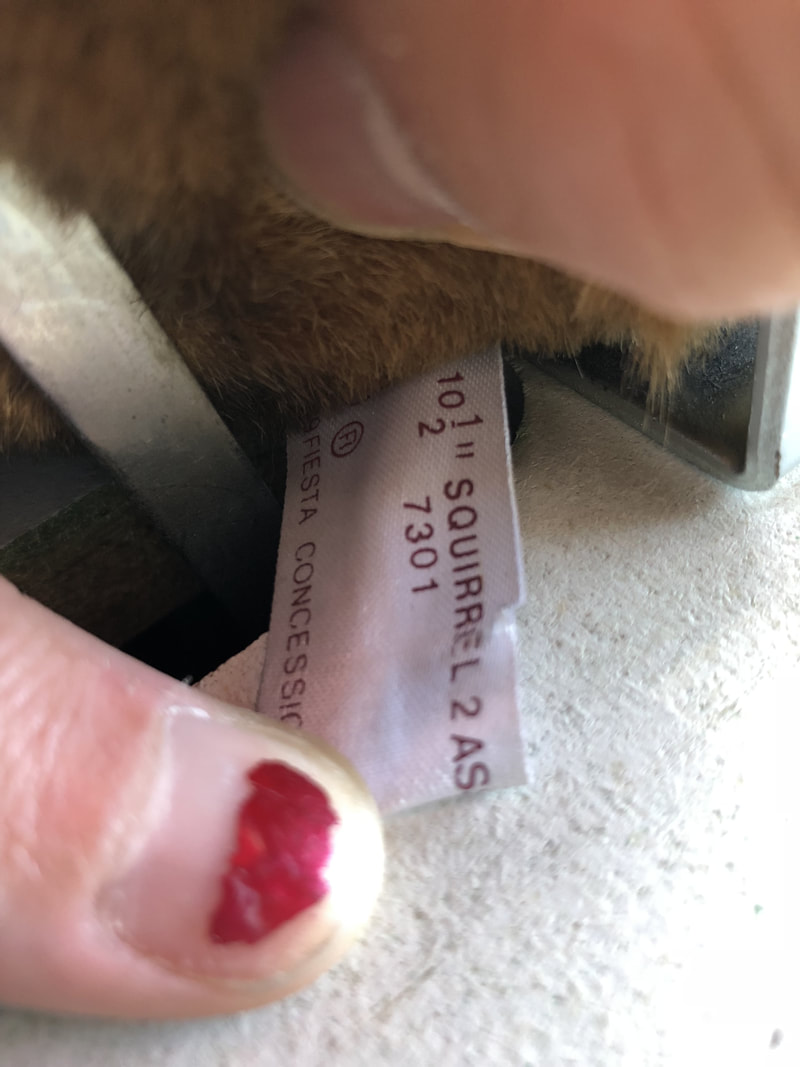
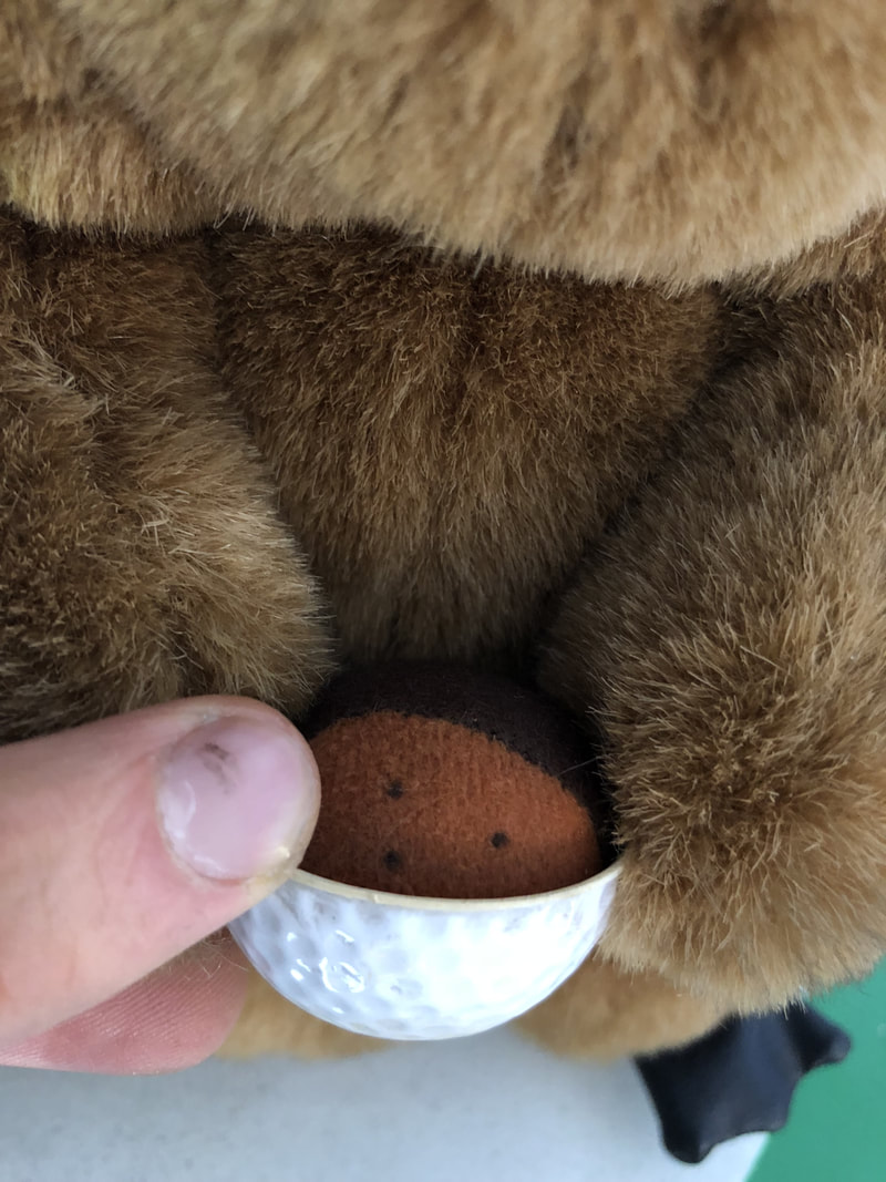
The topper on Tee'd Off is huge; it's one of the tallest (original) toppers I've seen on a pinball machine. The gopher talks and moves from side to side, with flashers going off on either side. One of the most interesting things I discovered about the gopher topper was that... it isn't a gopher. Taking a peek at the label attached to it shows that it's actually meant to be a squirrel. Not only that, but the golf ball that the squirrel is holding is an aftermarket addition that Gottlieb made at the factory. The original toy manufacturer sewed an acorn into the squirrel's hands. Makes sense for a squirrel, right? Gottlieb then tacked half a golf ball over the top of the acorn and voila; they turned it into a gopher!

Original manufacturer's label attached to the gopher (squirrel) toy.
The golf ball covering the acorn that was originally sewed into the squirrel's hands.
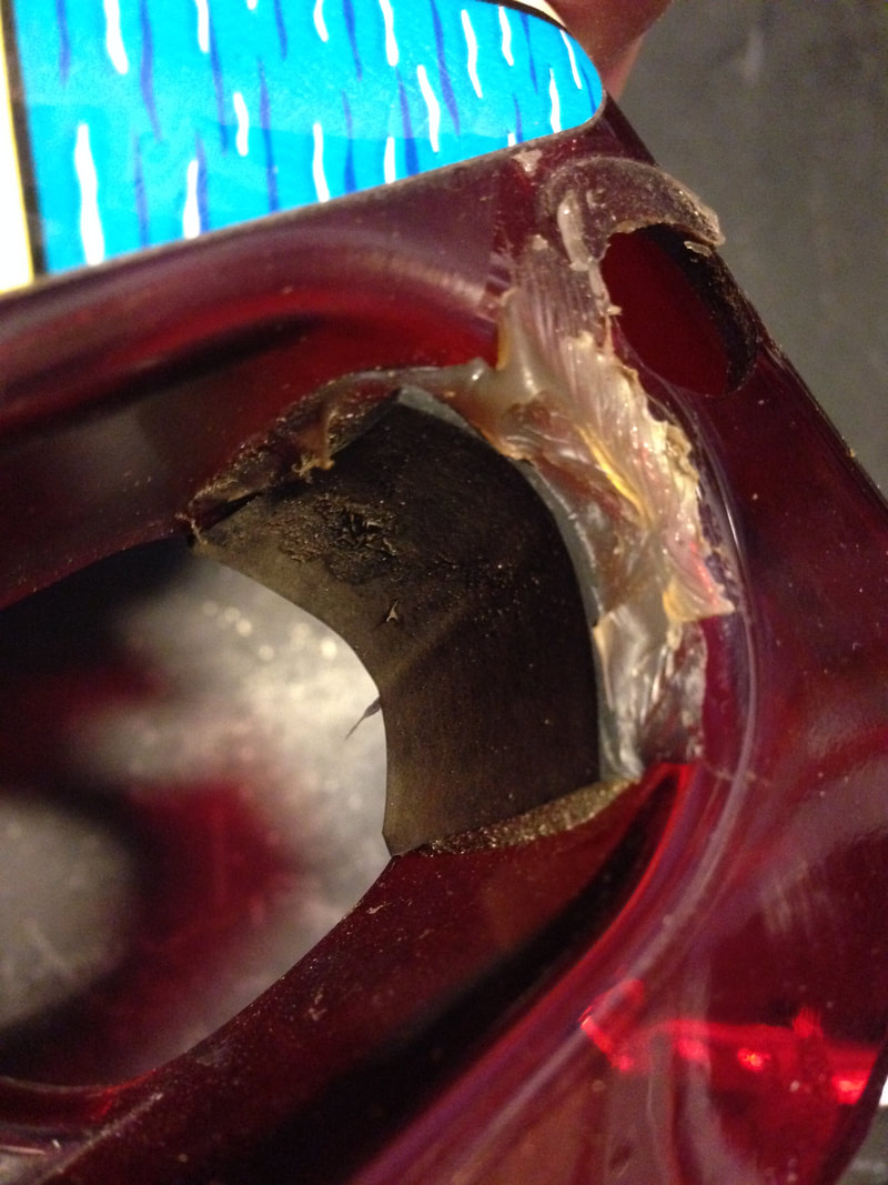
The topper was in average condition overall. The plastic cover was cracked at some of the screw holes and the central screw hole at the bottom edge of the cover was completely gone; it had been replaced by a section of plastic that had been silicone glued into place. It worked well enough. The topper cover was missing most of the screws that secured it to the top of the backbox, so I installed some.
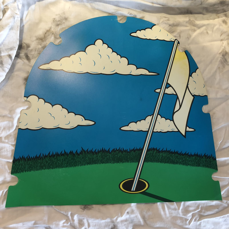
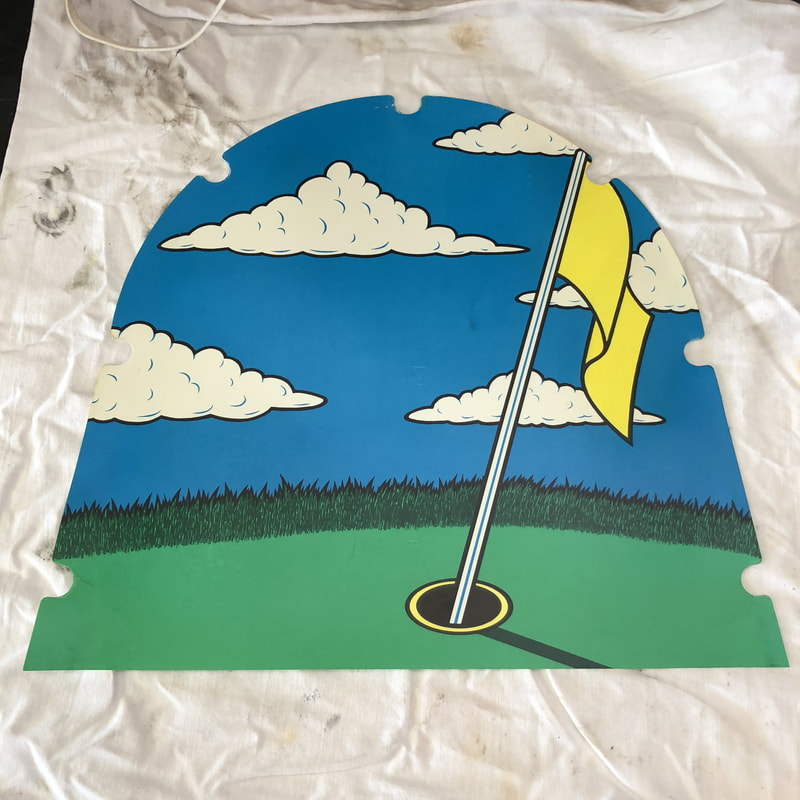
The only other thing that was missing was some of the colour in the topper decal. Looking at it, you might not realise that the flag is actually meant to be yellow. The yellow fades really badly and was almost completely gone on my machine. The rest of the colours were OK. Fiona suggested using a paint pen to recolour the flag but the decal is made of plastic and paint just won't stick to it. We ended up using a yellow Artline calligraphy pen from Officeworks which turned out to be the perfect colour. Looks like new now! Completely new topper backing plastics (part no. 30022) are also available (PB Resource).
Topper decal in original condition with most of the yellow faded.

Yellow recoloured and looking good!
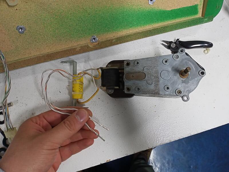
The last thing that needed attention was the motor and gearbox that made the gopher move. The gearbox was very loud and appeared to struggle to move the gopher; it made a lot of noise. I figured it was time to service the motor and gearbox assembly. To work on this assembly, it is easiest to remove the entire topper and take the motor and gearbox off separately. Inside the backbox, there are four wingnuts that secure the topper to the backbox. Undo these (don't drop the washers), and undo the connector that powers the motor and lamps. Then, the entire assembly can be lifted off the game.
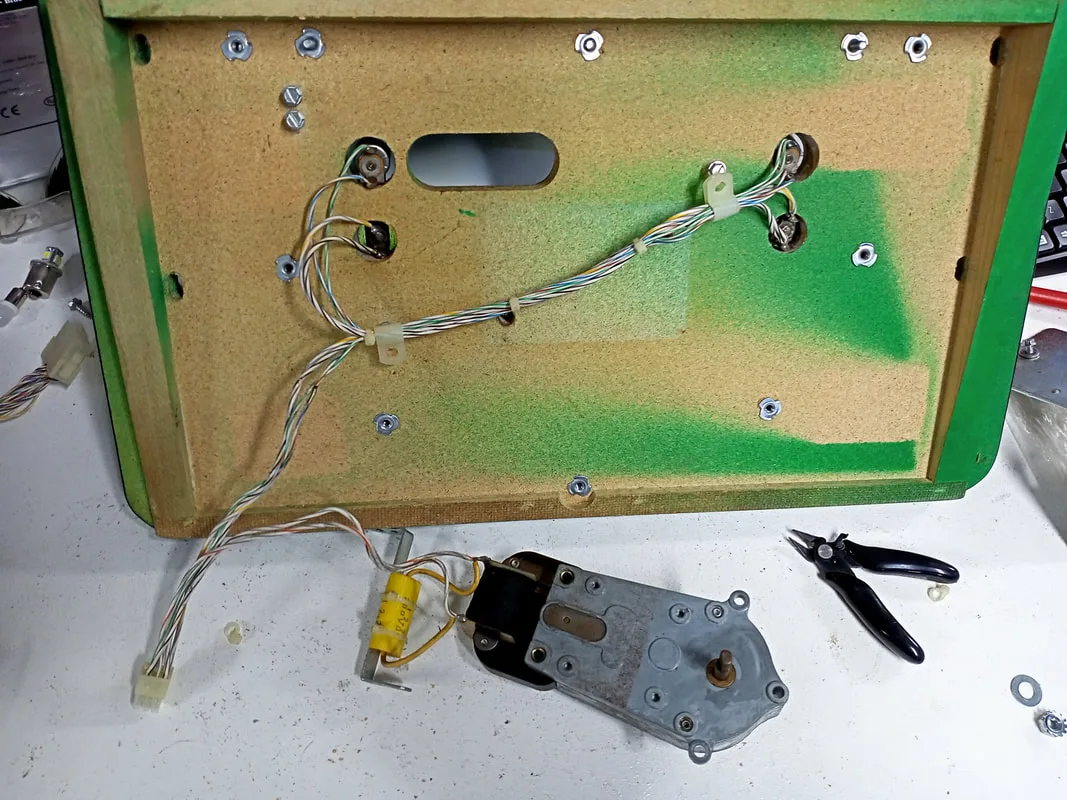
Motor and gearbox attached to the same connector as the topper lamps.

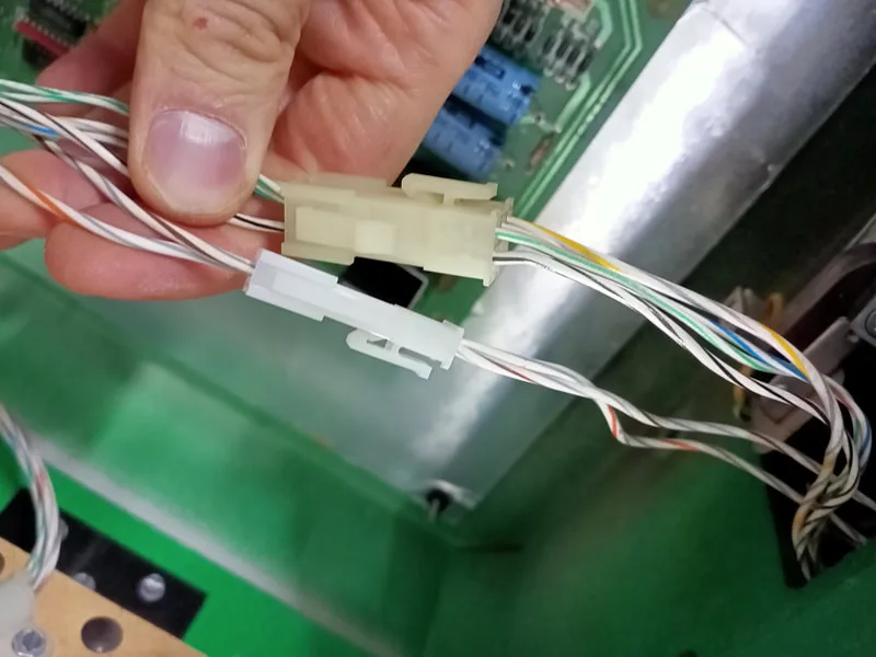
Here's the first area of difficulty. There is a single connector that powers everything in the topper, including the motor, two general illumination lamps, and two flashers. As a result, you can't simply remove the motor and gearbox to service them, as they are connected to everything else. You may think to detach the lamp sockets and bring everything with you to the bench, but the lamp sockets are screwed to the topside of the timber, and they can't be threaded through the holes. My solution was to remove the wires connected to the motor from the connector (grey-grey-orange and grey-grey-brown) and install them into their own connector. That way, I could remove the motor and gearbox for servicing and leave the lamps and other wires intact. I wish Gottlieb had done it this way to start! I learned that the terminal pins Gottlieb used are very, very similar to those supplied in Jaycar's series of miniature nylon Molex-style connectors. This means that the original Gottlieb terminals can be inserted straight into the new connector. No need to install new crimp pins!

Wire terminals removed from the shared connector.
New connector for motor pins installed.
Next, you'll need to remove a couple of E-clips to detach the gearbox from the armature that moves the gopher. The gearbox was riveted shut, so I drilled the rivets and tapped them out with a punch. They didn't come out easily!
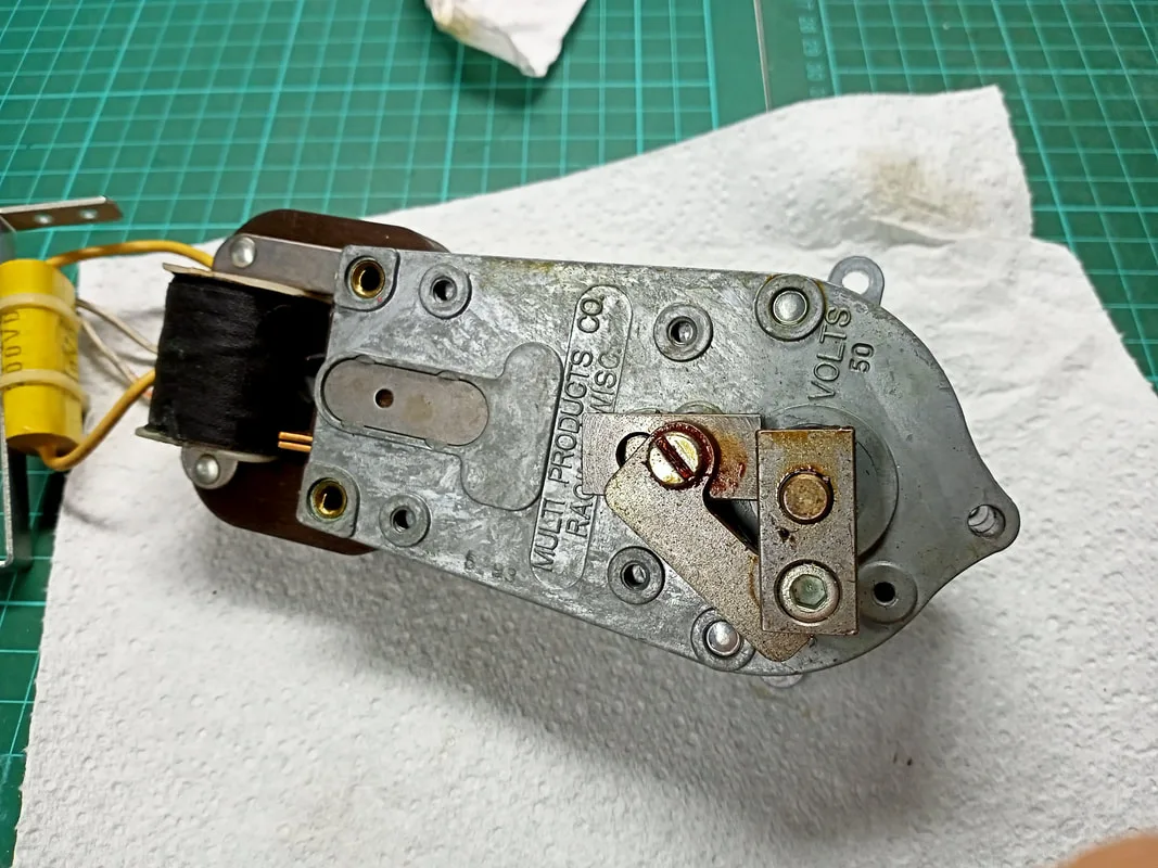
Gearbox, front view.

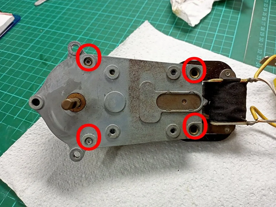
Gearbox, rear view. Rivets marked in red.

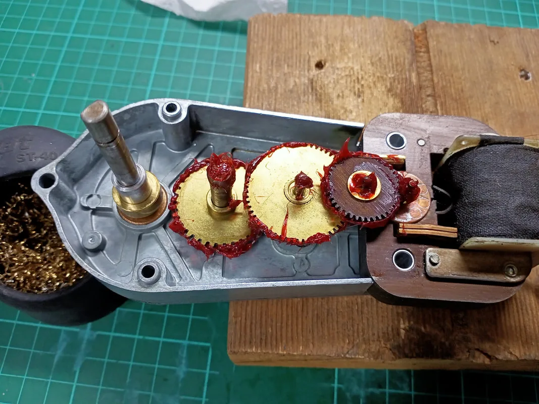
Once inside, I noticed that there wasn't much grease in the case. It looks like very little was applied at the factory. This was probably contributing to the noise of the assembly. I cleaned all the old grease from the gears and casing, and applied some PTFE-based lube (Supercheap).
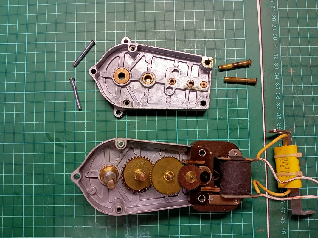
Interior of the gearbox casing.

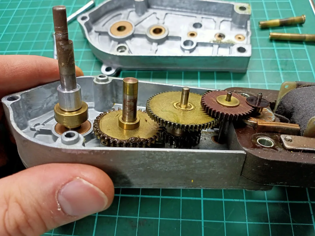
Factory-applied grease on the gears.
To reclose the gearbox casing, I opted for screws instead of the original rivets to make future disassembly jobs easier. I found some suitable countersunk screws for the bottom edge of the gearbox, but couldn't find any countersunk screws that were thin enough to go through the holes towards the top edge of the gearbox. I had some standard Phillips head screws that were a good size, but their heads were too large and they protruded slightly from the hole. This made it impossible to attach the gearbox to the mounting bracket, so I ground down the heads of the screws until they were flush with the gearbox, being careful to leave the heads intact and usable.
Gears cleaned and fresh lube applied.
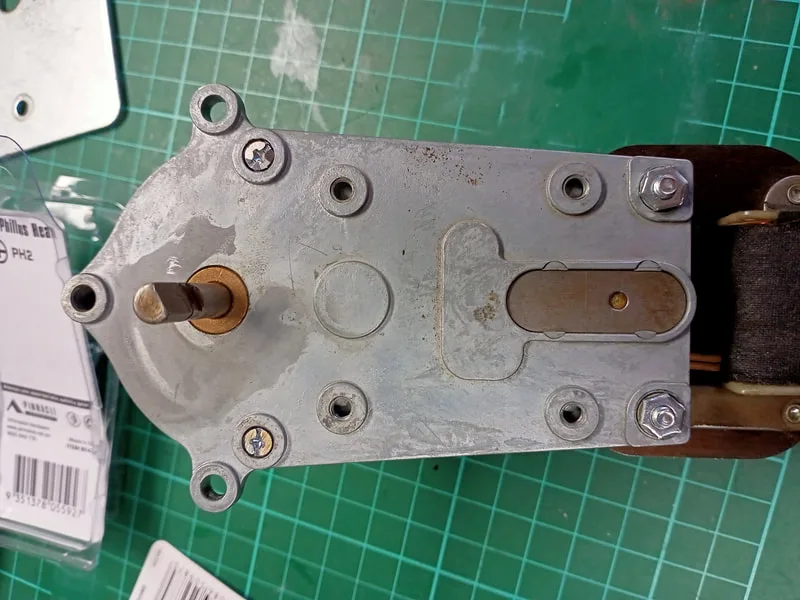
Gearbox case closed, with screws flush with top of casing.

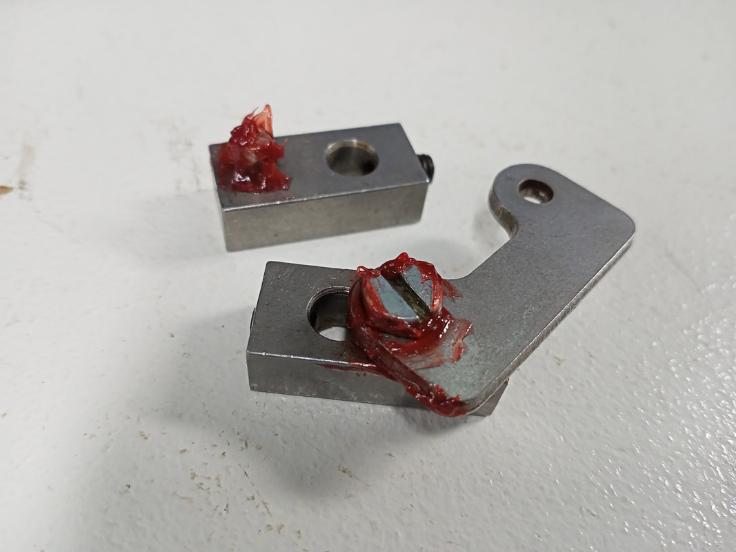
One last thing before reassembly. I lubed up a couple of other metal-to-metal contact points including the armature joins that connect the motor shaft to the gopher. These had old, crusty grease on them which I cleaned off and replaced.
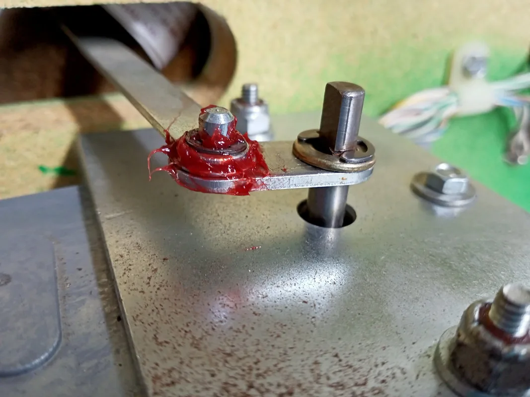
Lubrication point 1.


Lubrication point 2.
That was it. Everything was reinstalled into the cabinet and worked as expected. The motor was still a little loud when running, however the laborious grounding noises I had heard were gone, and it was now running quite smoothly.

Motor and gearbox serviced and reinstalled into the bottom of the topper assembly.
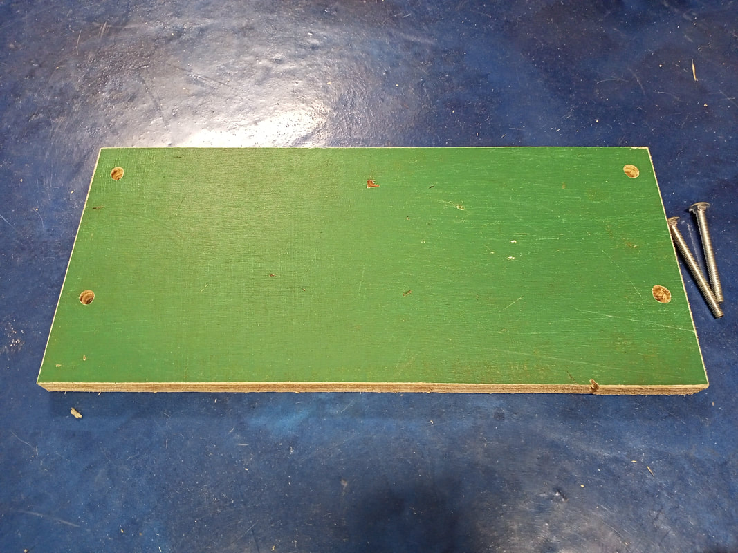
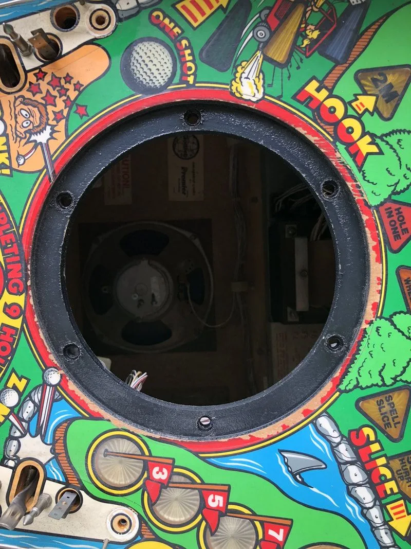
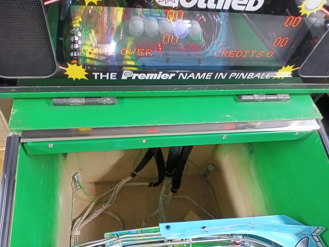
While the topper is great, there are times where I need to remove it from the game in order to move it around the games room; the ceilings are too low for it at the edges. Sometimes, I'd like to leave it off for an extended period. This is easy to do, as it simply unbolts from the backbox via four wing nuts, and a couple of connectors need to be undone before the topper is lifted off. Games originally shipped with a plate to cover the hole in the top of the backbox, so that dust and other foreign objects wouldn't fall in. My plate was missing, so I decided to fabricate another one. I decided to use some timber, as I had a some scrap timber panels lying around (in green, no less!) Some quick measuring told me that the holes were 102 mm and 384 mm apart. The hole is not rectangular, but has a small outcrop at the front edge. I cut a large rectangular piece for ease of cutting.

Timber panel cut with bolt holes drilled.
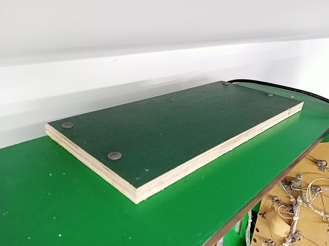
It fit first try, so that was a good sign! The bolts that secured the topper were quite long, which was why I used a relatively thick piece of timber. Otherwise, the bolts interfered with the opening and closing of the backbox light panel, so check the clearances on your own machine. The bolts on my machine were also not original, so this may have contributed to the issue.

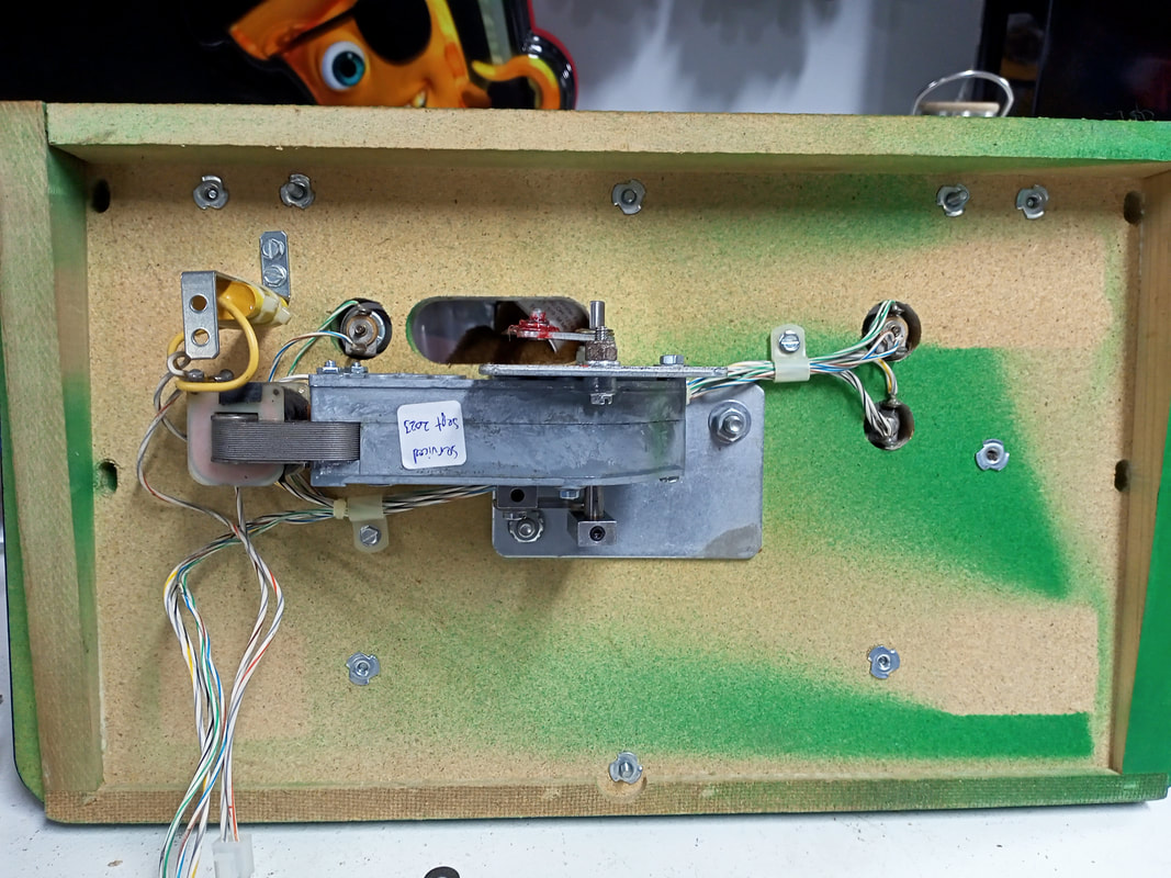
Timber cover panel installed on backbox.
Underside view; note the length of the bolts.

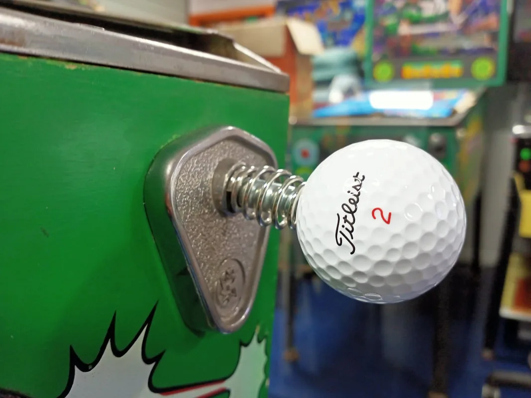
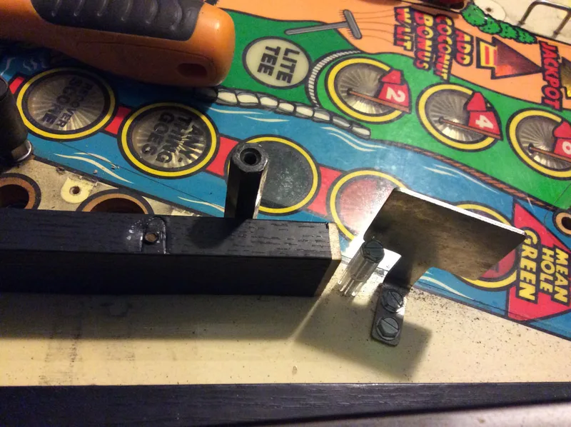
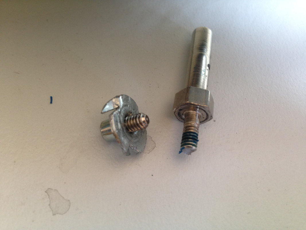
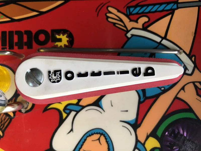
New custom golf ball shooter rod.

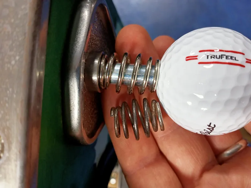
New barrel spring installed.


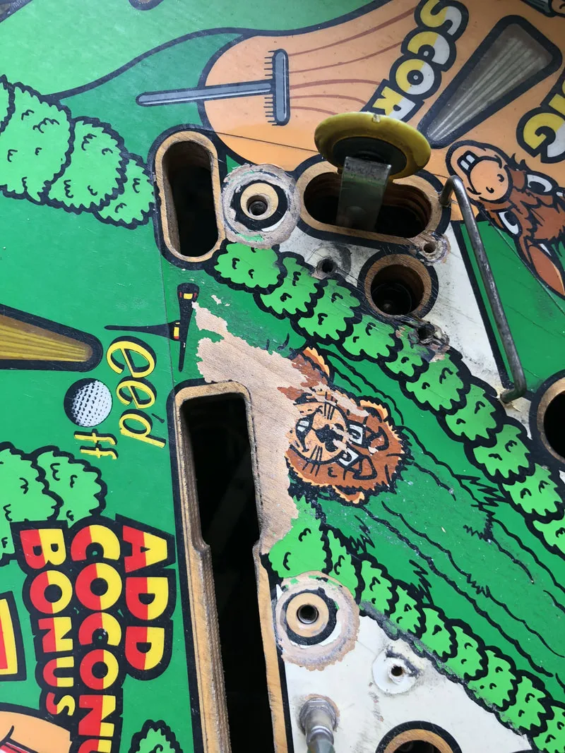
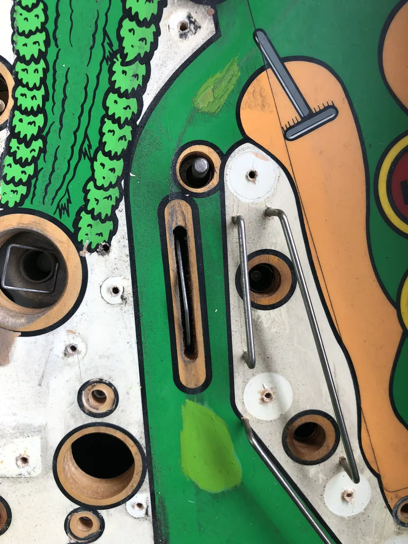


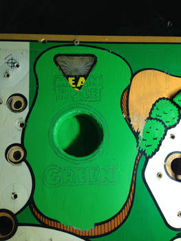
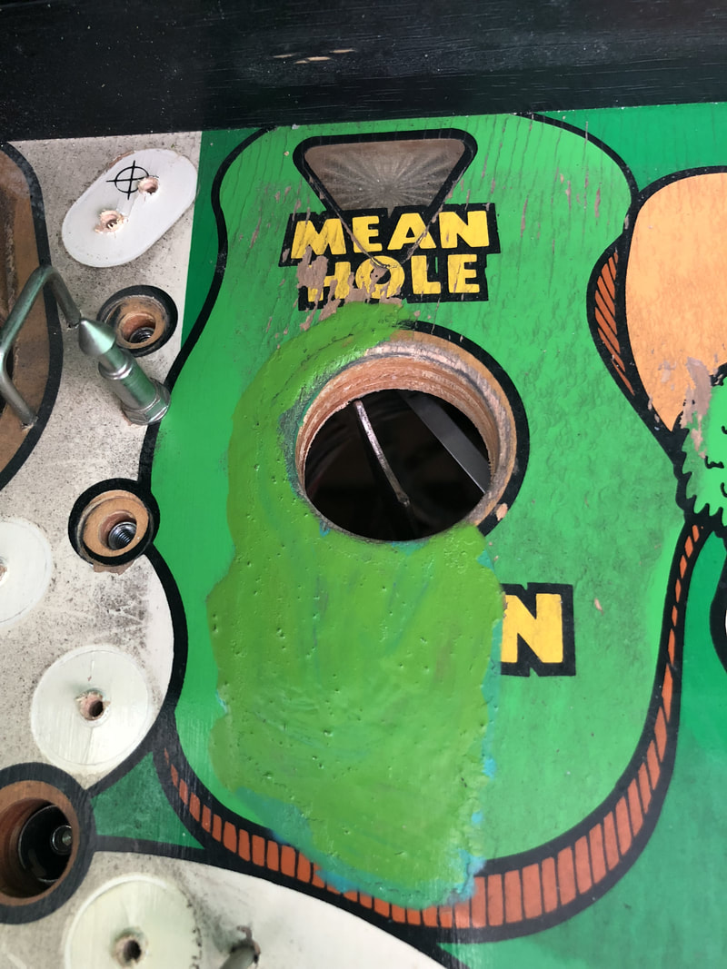
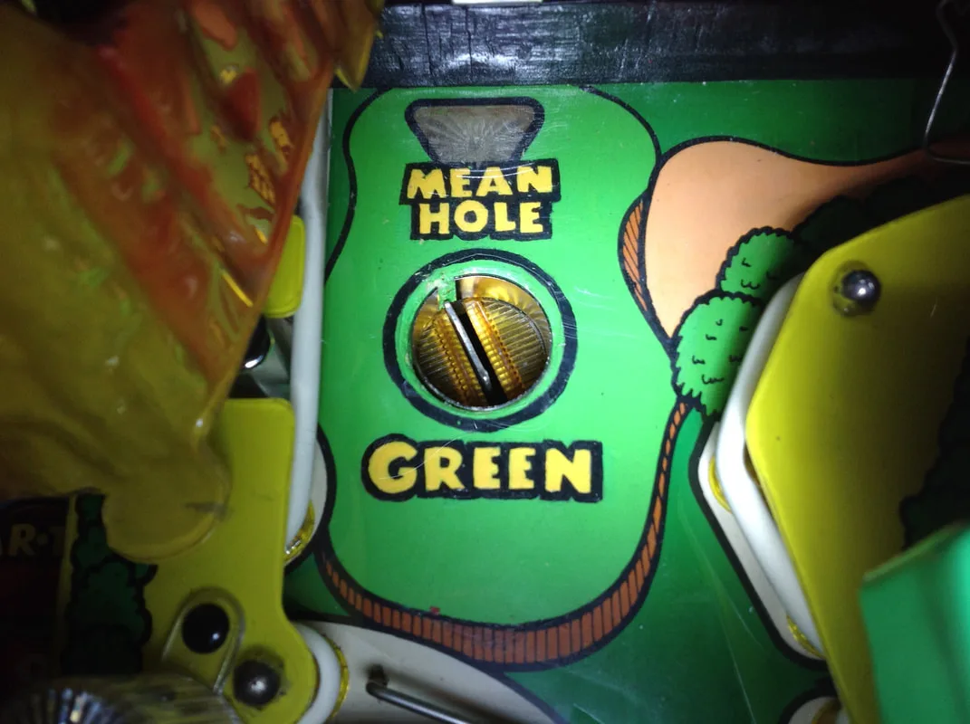
Mean Hole Green area after a basecoat of green.
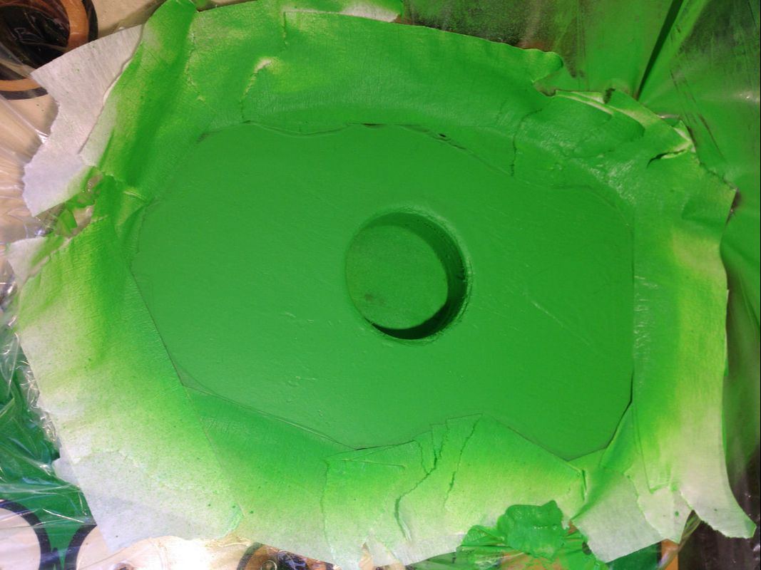
Those were the easy colours to mix. Up until this point we had been doing all of our touch-ups with Createx Airbrush Colours. These were great, but the colour range was a little lacking. We could not match the dark green on the main part of the playfield. It was a weird green with a little fluorescent element to it, but was still quite deep and bold. As we couldn't get an accurate match with our current colour set, we grabbed a full pack of Createx Wicked Opaque colours (Airbrush Megastore). This set had some different shades that would make matching easier. Plus, Wicked is reportedly a better range of Createx paints which is more suited to this kind of work. We figured out the best match for the darker playfield green was a base of Apple Green, with a few drops of Phthalo Green for darkness, White, and some Golden Yellow. The brown on the gopher and dog was mainly Brown with a mix of Red Oxide, Golden Yellow, Crimson, and White. The light coloured sand was made with a Golden Yellow base mixed with small amounts of Crimson, Red Oxide, and White. The red ring around the gopher wheel was repainted with Red and White. And finally, the white areas of the playfield were made with White, Golden Yellow and Grey.
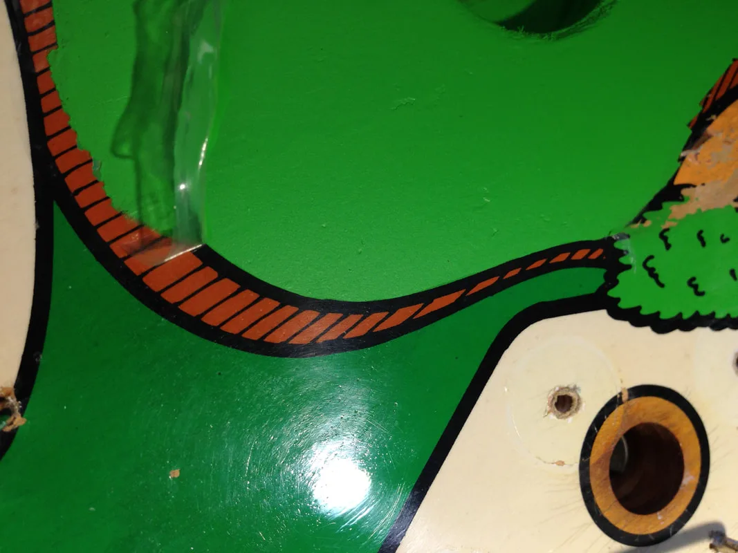
Peeling up the liquid tape to reveal a perfect rounded edge after airbrushing.

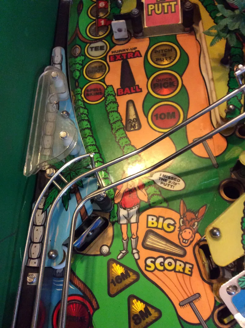
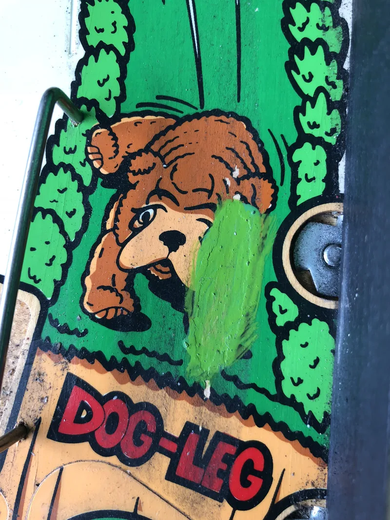
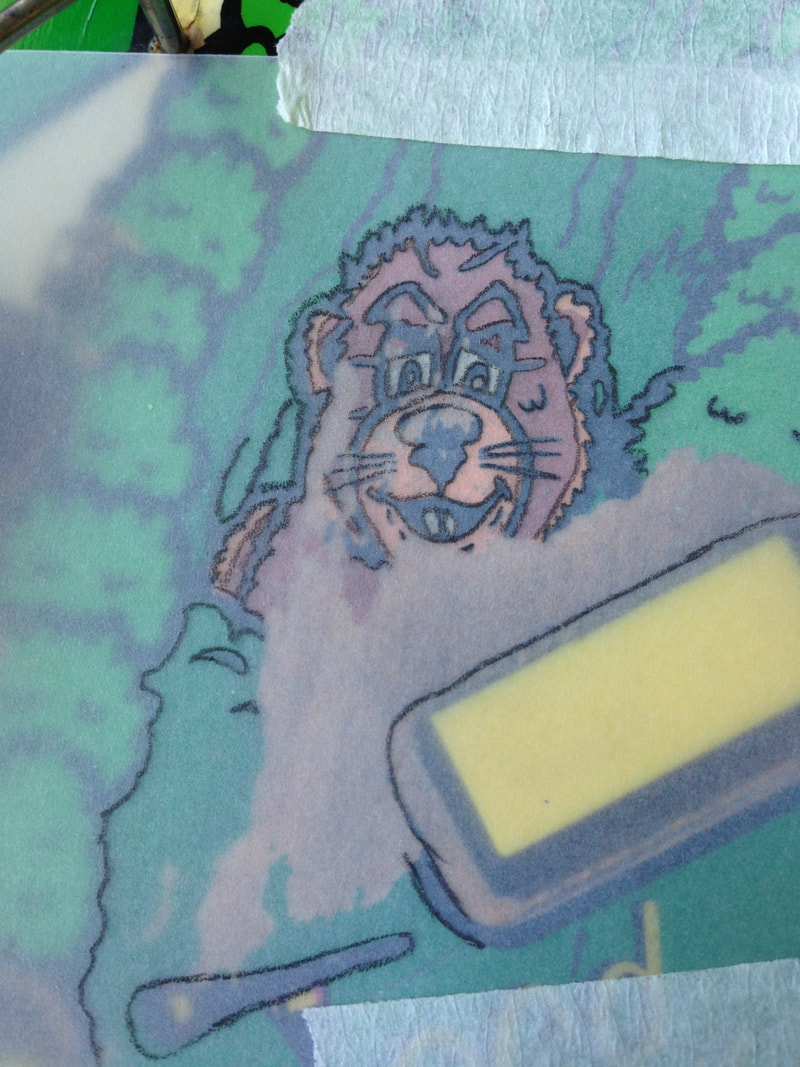
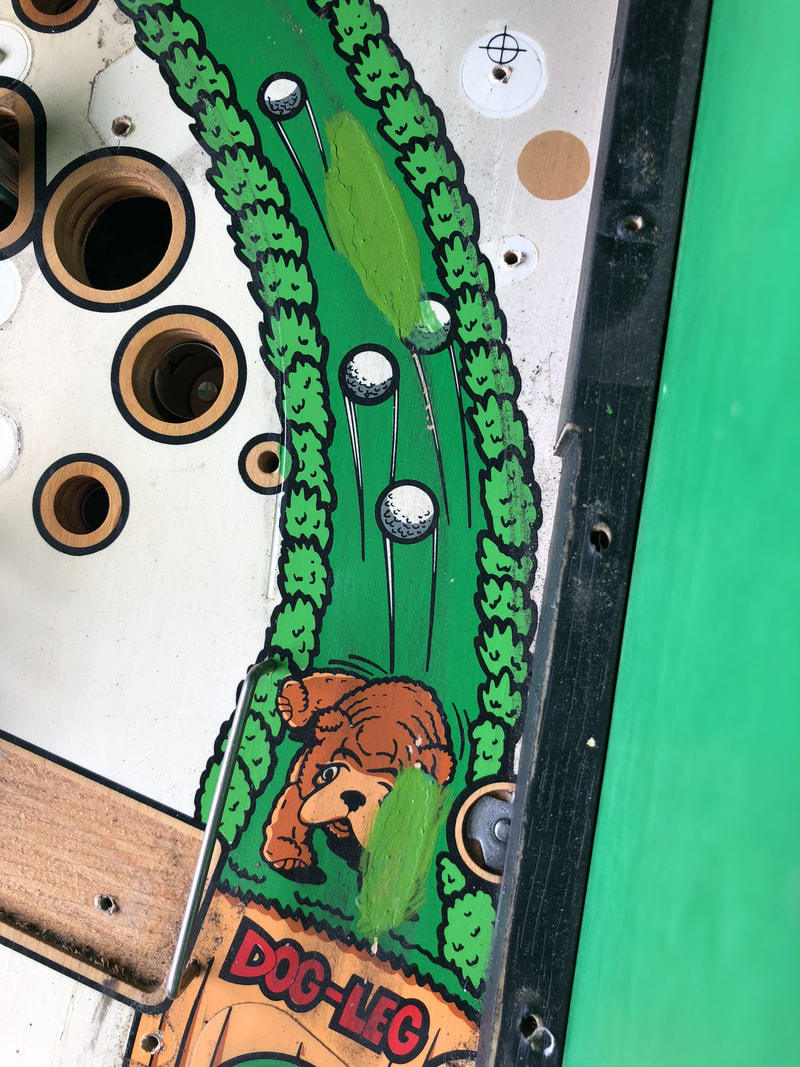
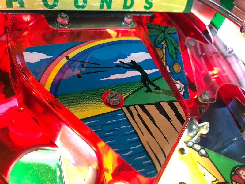
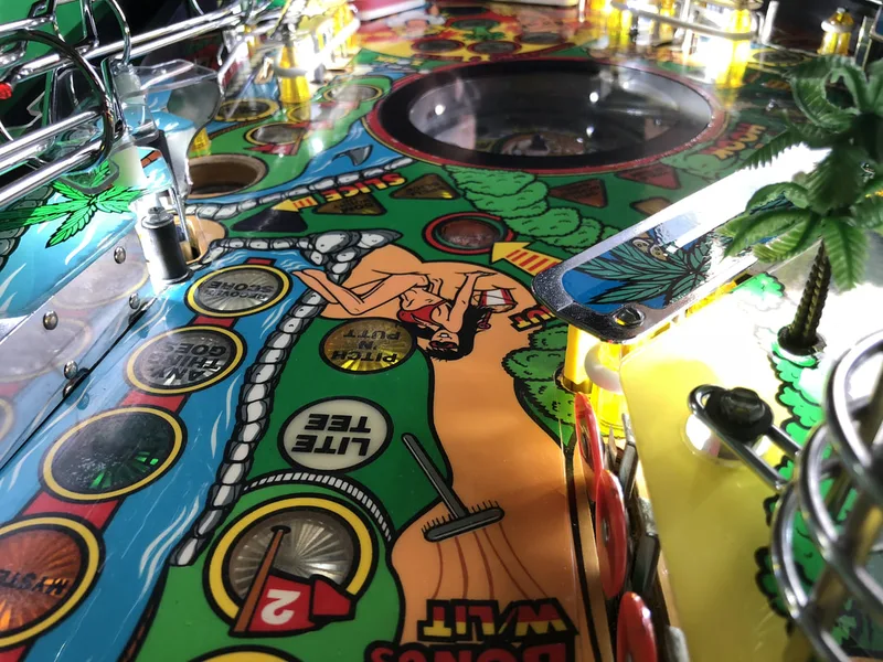
Next, Fiona worked her magic on the playfield artwork. Some of the areas were a bit difficult as they were worn away to the point that the original artwork needed to be reconstructed based on reference images. Google is always a great way to find reference playfield images in cases like this. We found an detailed gallery of images on HSA Pinball of a Tee'd Off that had been restored and it had some great close-up images of the areas we needed to repair. We used these images as references. Then, we used tracing paper to trace over the damaged areas and drew in sections that were missing. Once everything was drawn up, we could transfer the image to the playfield. This was done by flipping the tracing paper over, tracing over the image on the reverse side, and then flipping it back onto the original side. The image was then traced over again to transfer the pencil lead to the playfield, leaving a stencil to paint.

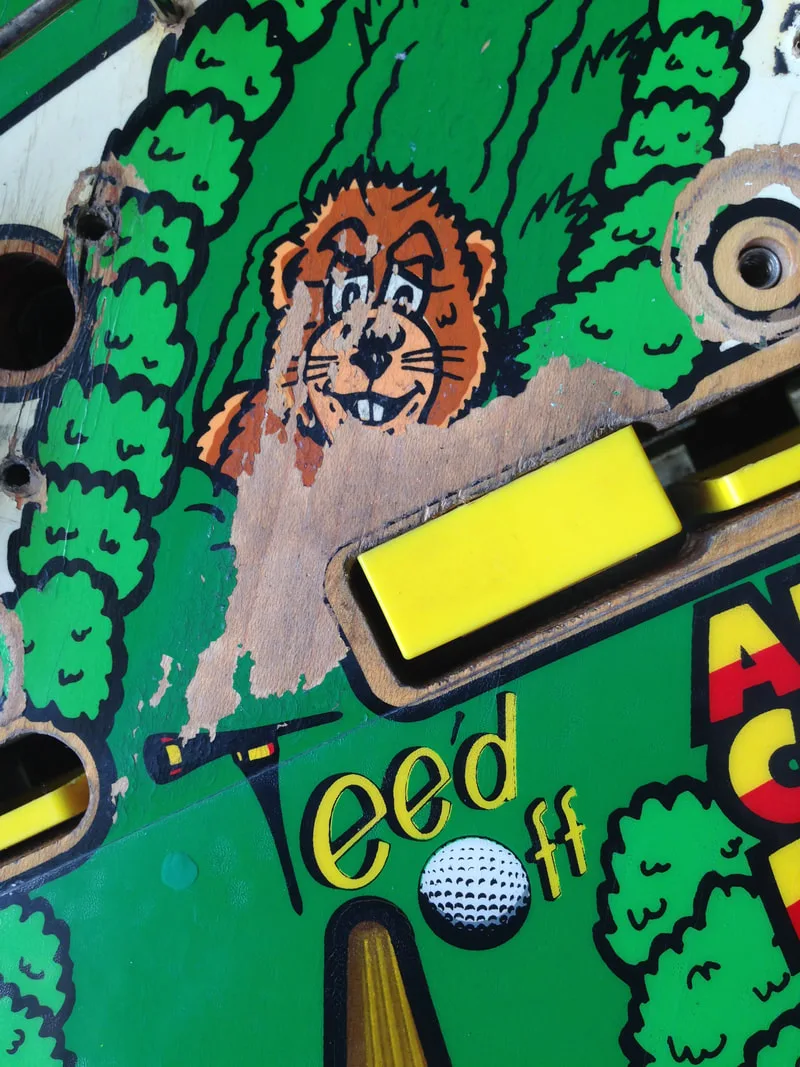
Tracing over details of the gopher in the centre of the playfield.
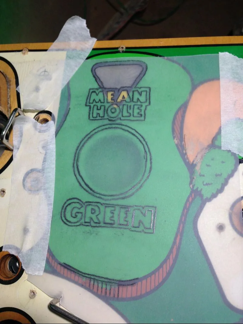
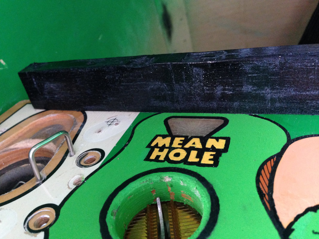
Tracing over the Mean Hole Green text. The missing areas have been drawn in.
Image transferred to playfield for painting.
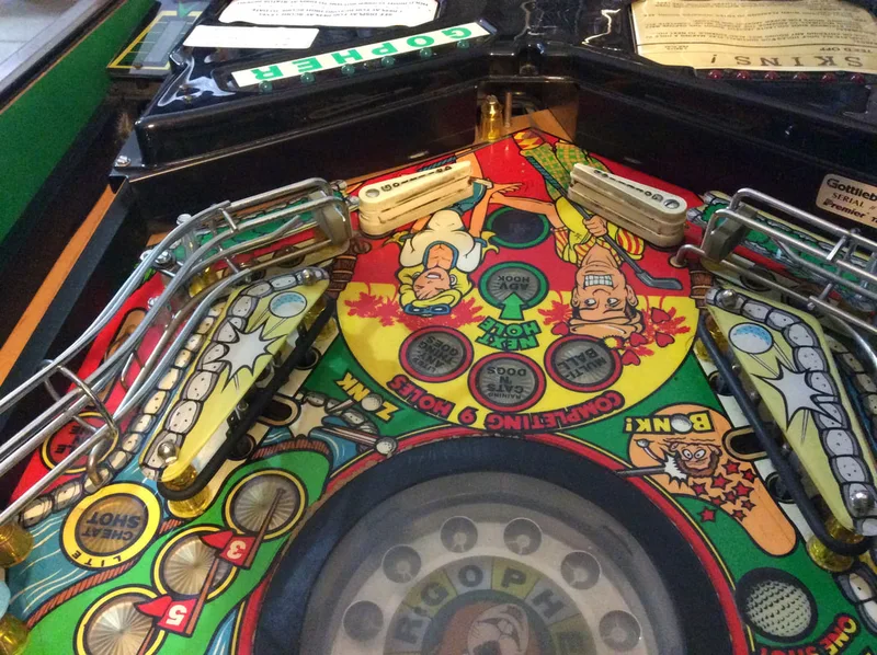
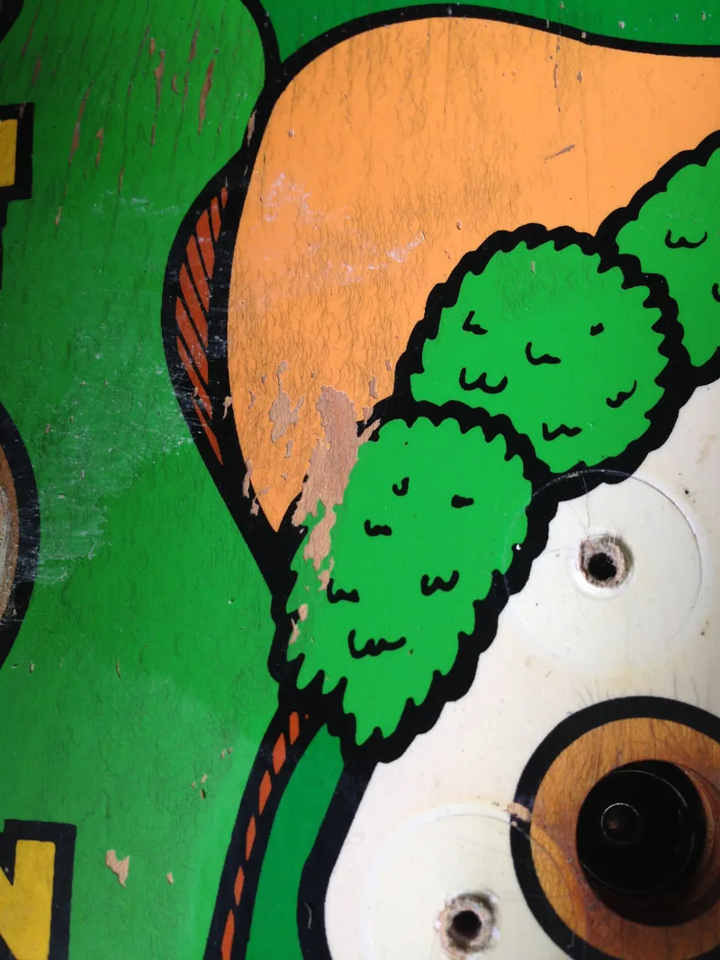
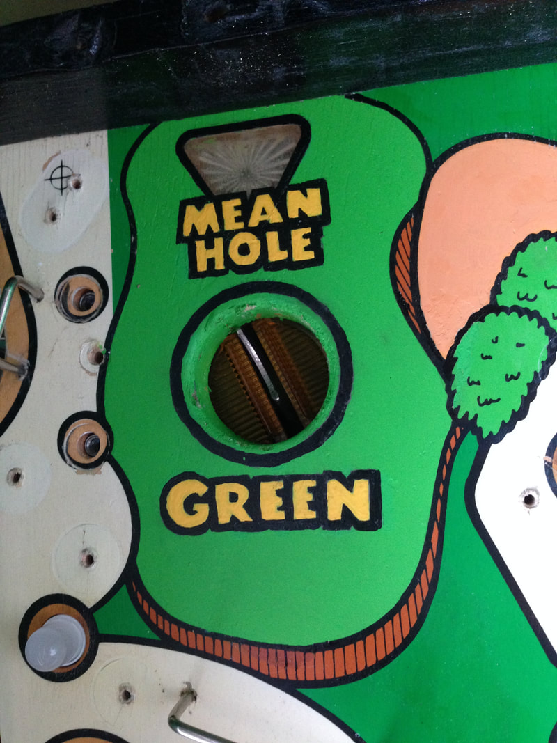
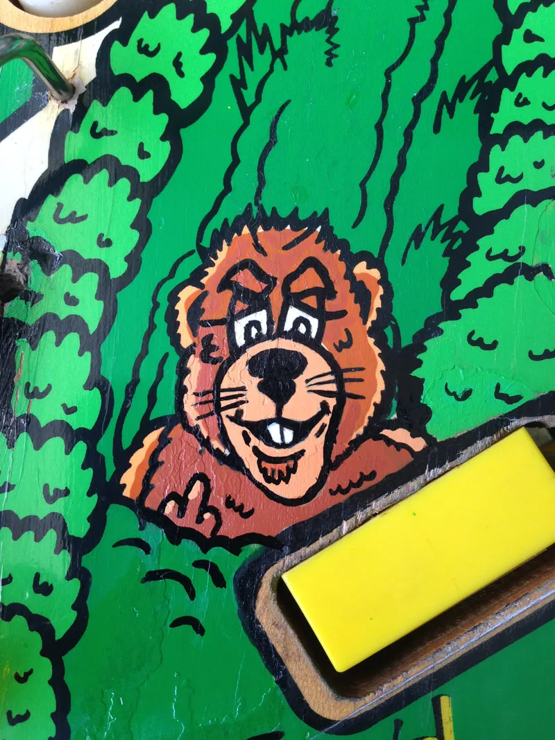
The large green area of the Mean Hole Green (upper playfield) were airbrushed, while the finer playfield details were touched up with a brush. Some areas were more fiddly than others. The Mean Hole Green was pretty simple, with bold lettering and thick lines. For the gopher and the dog, Fiona used an extremely fine brush... and a lot of patience. Some of these areas turned out fantastically. I'm lucky I have a partner that's got the magic paintbrush touch, because I would have butchered these beyond recognition! Here are some before and after images for comparison. See if you can spot the little custom detail we added to the gopher...


2019 edit: Well, it's just my luck. After I finish this restoration, somebody scans and releases a decal of the mean hole green area! This would have made the restoration of this area so much easier. You can either use this decal as a painting guide, or print and apply it direct to the playfield.

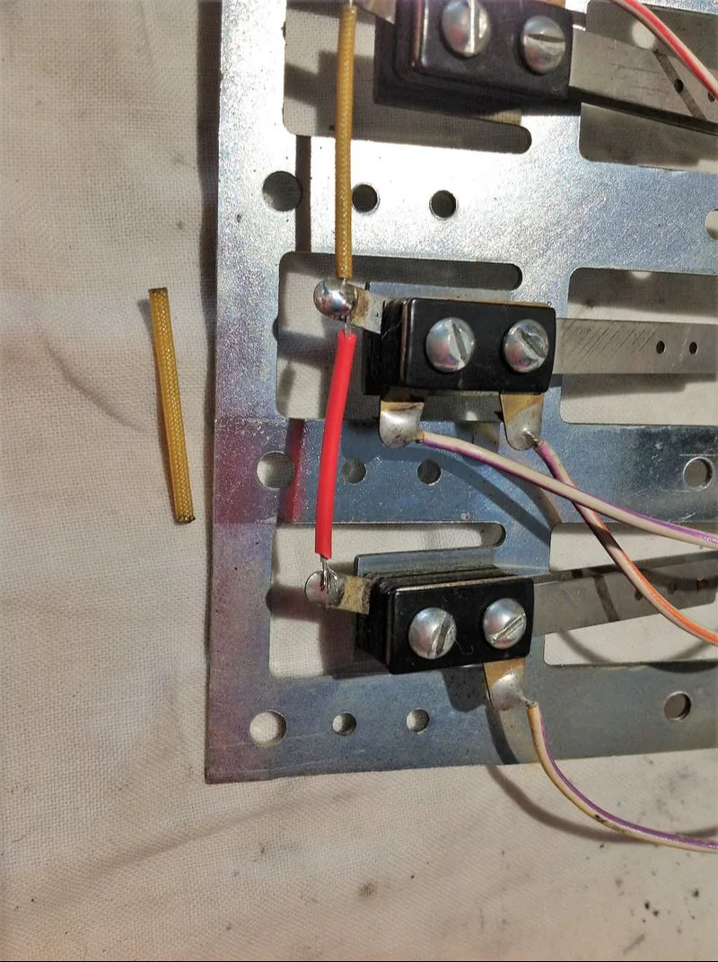
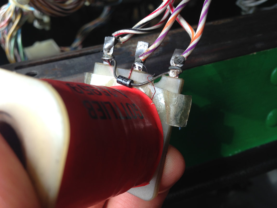
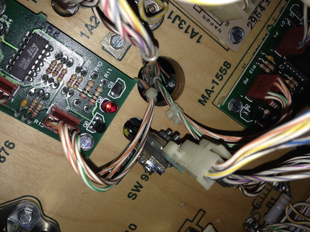
Photo of the switch wiring before breakage. The common wire is above the switches and insulated with yellow insulation.
Broken wire in the process of replacement.

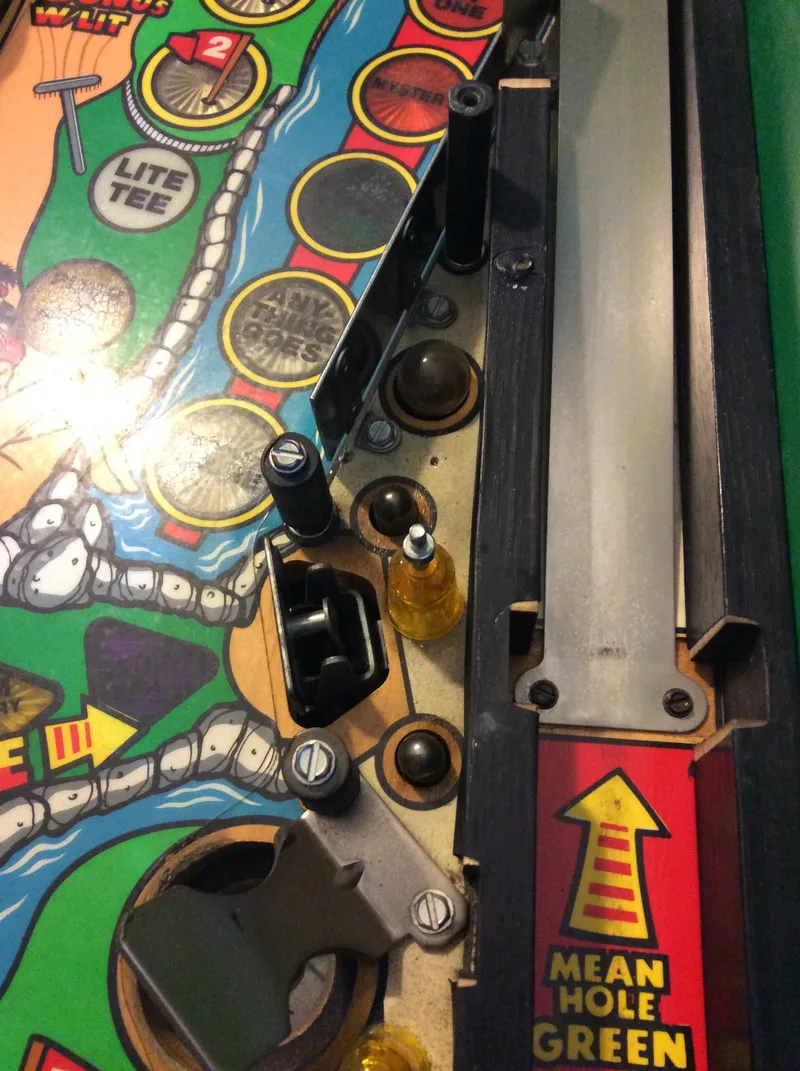
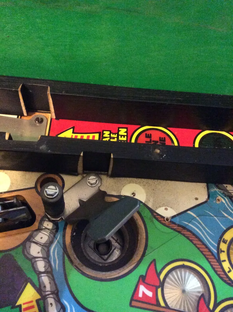
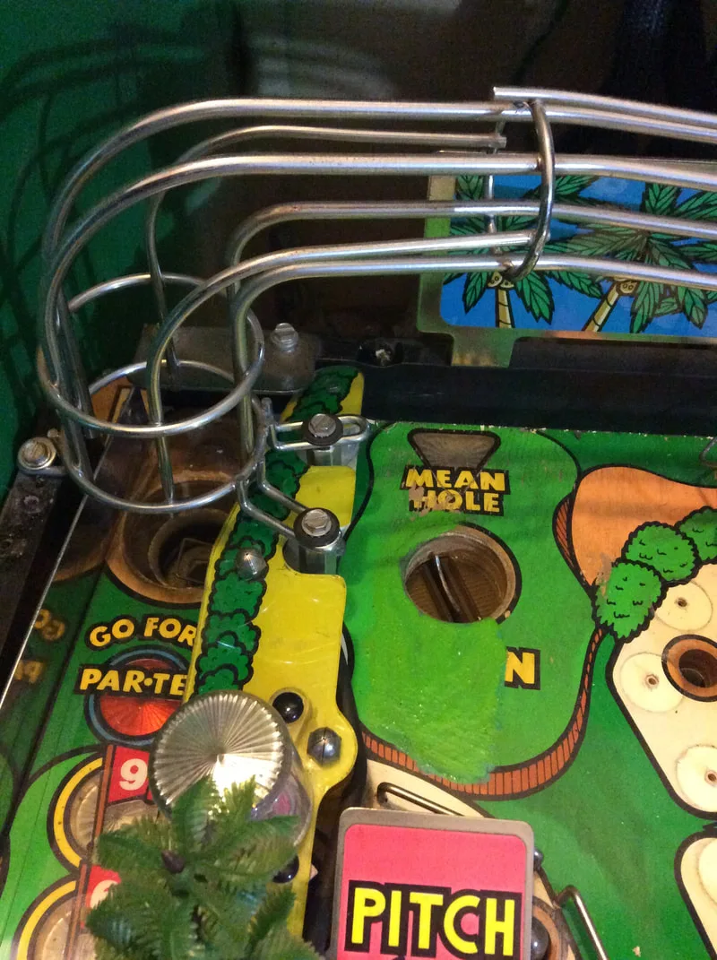
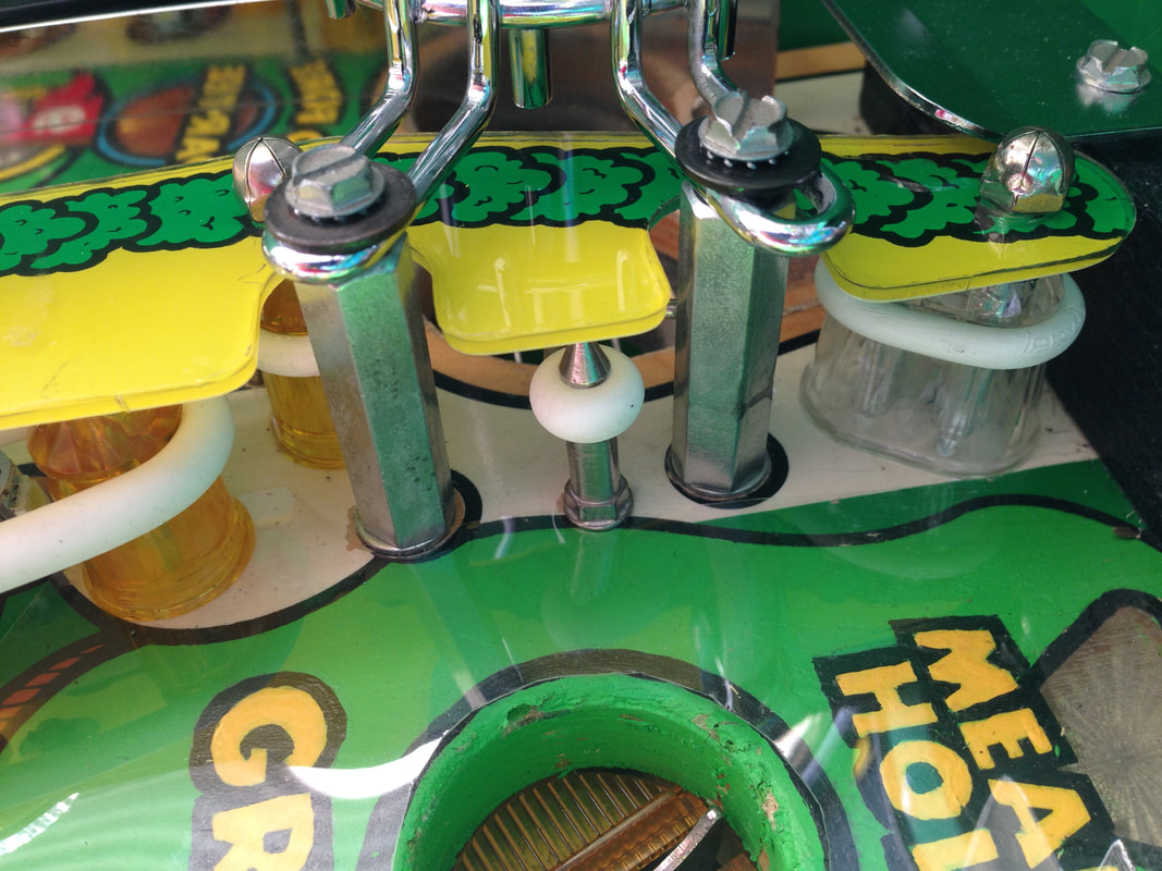
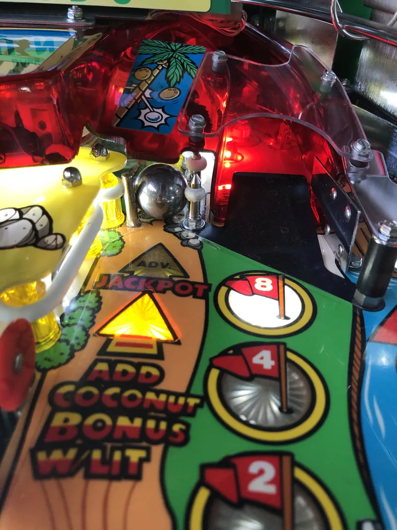
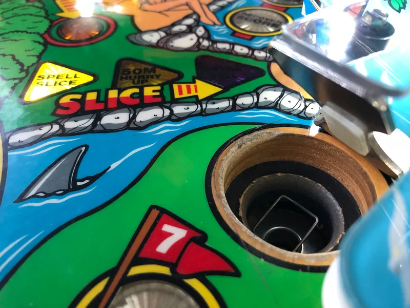
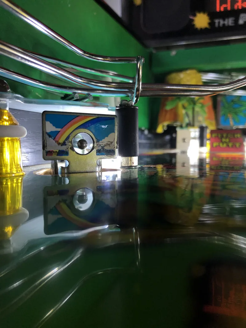
The other issue with the drop targets was that the centre target would sometimes have issues resetting. The coil would reset all of the coils, including the centre one, but the centre one would often fall back down again and it would take several tries for it to stay up. I looked over the assembly thoroughly after cleaning it and there were no problems with it at all. The problem turned out to be with the ball snubber above the drop targets. This metal piece was a little too low, such that the targets would hit it and would not be able to rise to their highest position. This is necessary for the targets to reset and properly latch. I'm not sure why the ball snubber was too low, when it was resting on the playfield posts that are supposed to give it the appropriate height. In any case, a washer under each of the star posts that support the snubber, which raised it far enough that the centre target could reset normally every time. Using 3/4" plastic washers like this (RTBB) also has the benefit of protecting the playfield artwork from further damage, as these posts get direct hits from the ball which causes them to dig into the playfield and scratch up the artwork.

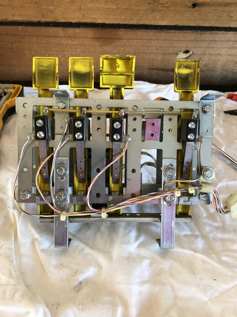
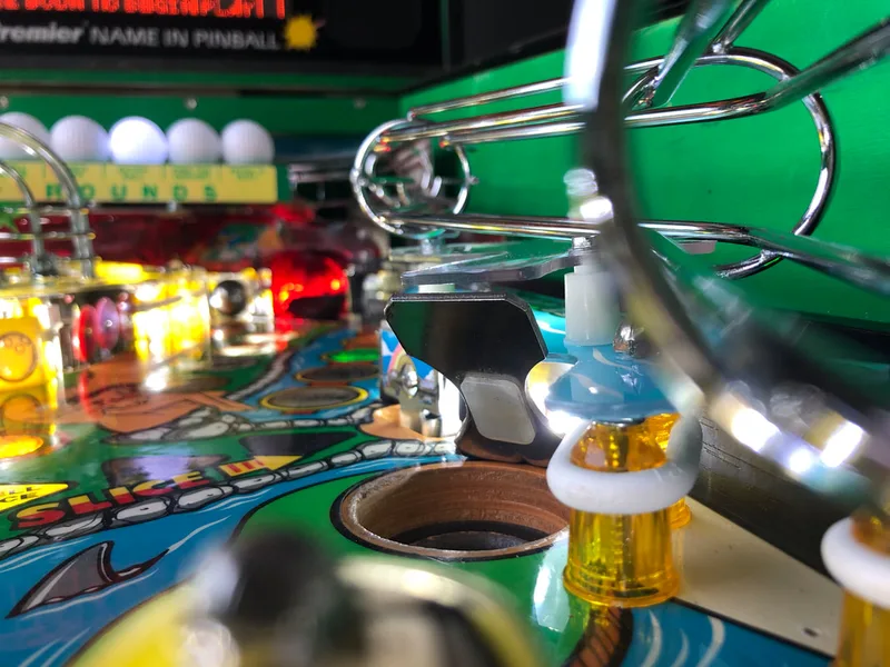
Front view of the drop targets with ball snubber above.
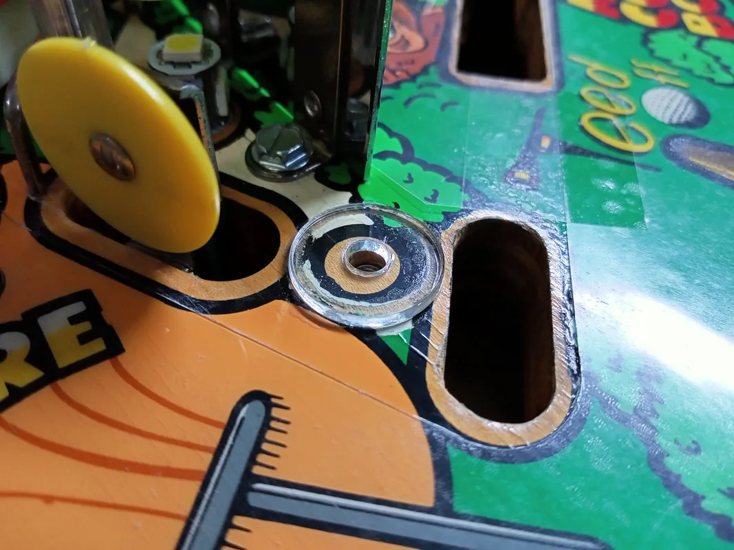
Washer installed under star post.

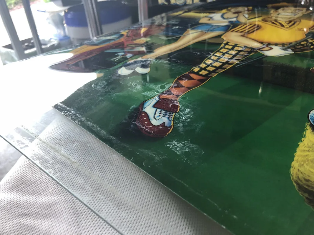
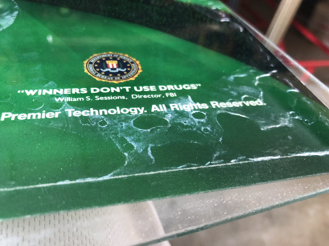
Residue on the Translite.


Residue on the Translite.

Too much pressure rips T-nuts out of the playfield.

Aftermath of trying to unscrew a post that was glued in place.

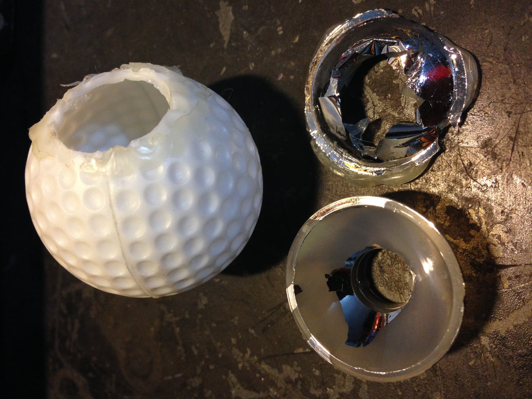
Original ball after removal of the reflector. The excess glue takes the reflective coating with it.
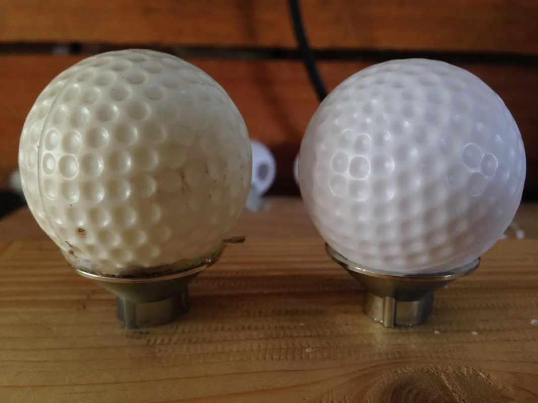
New plastic ball (right) compared to an original (left).

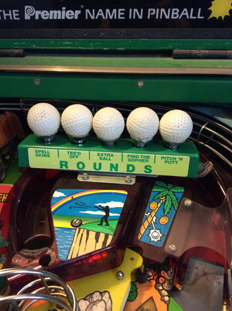
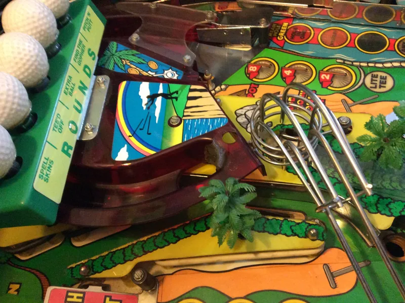
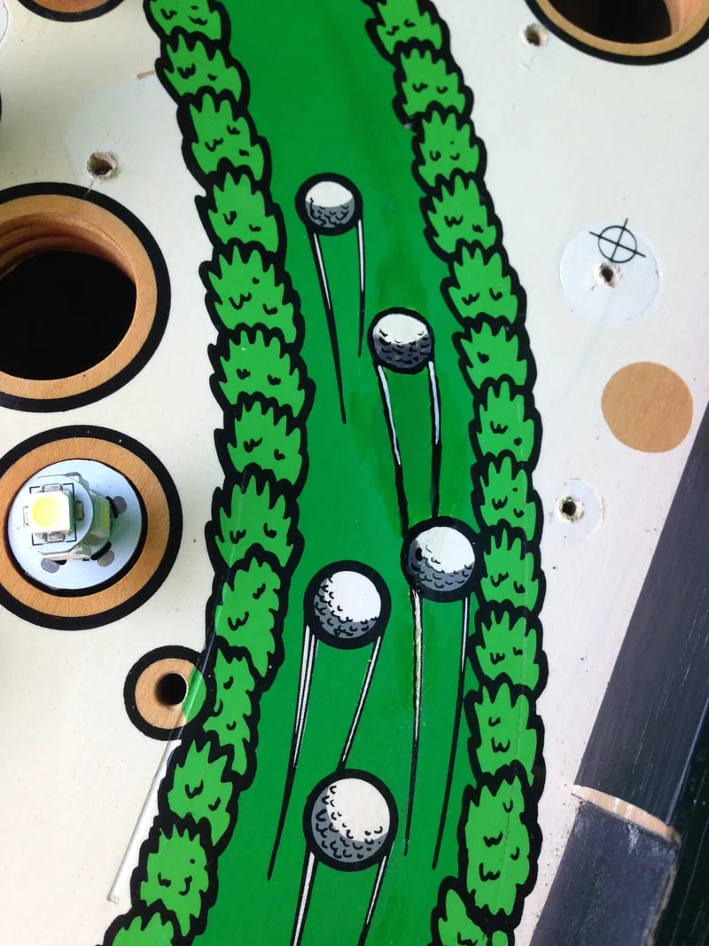
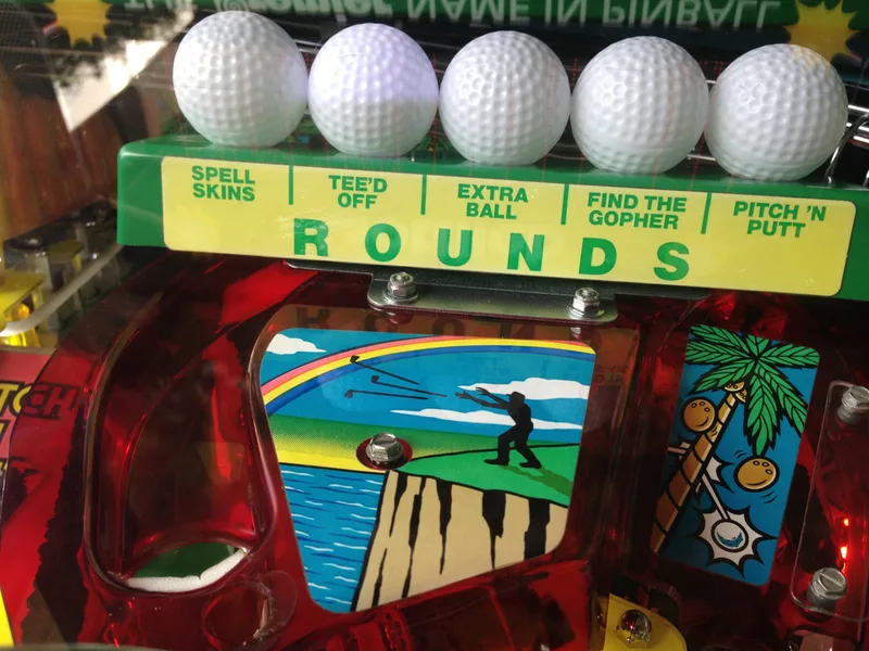
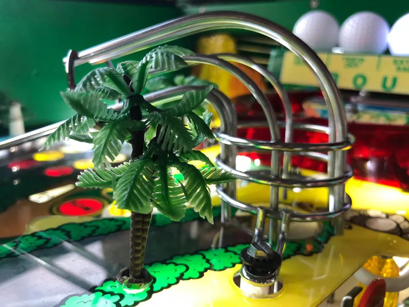
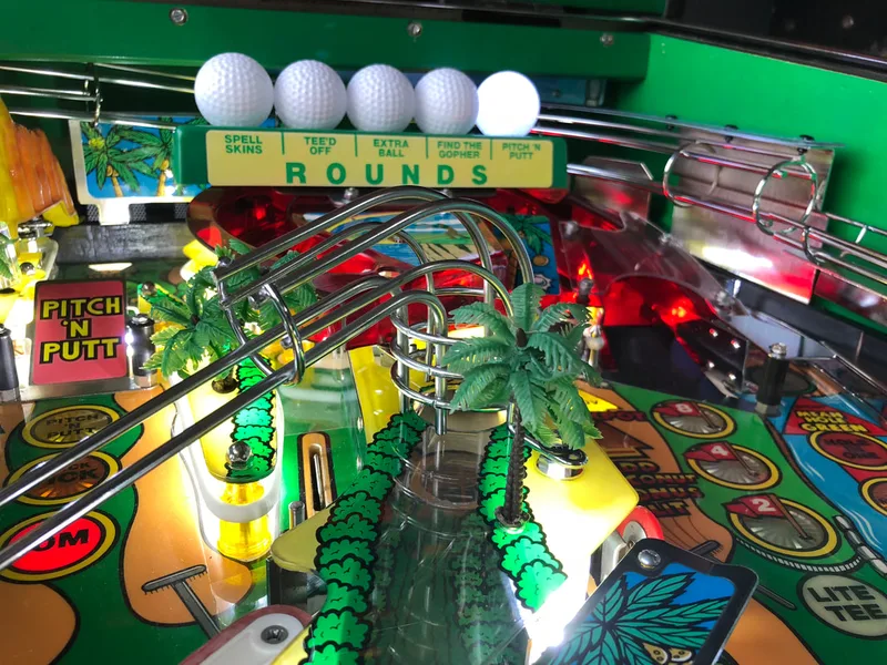
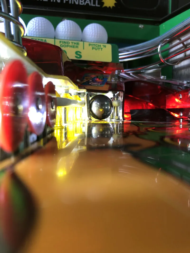
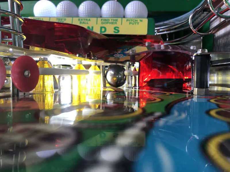
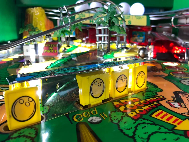
I drilled some new holes into the new balls. The holes on the original balls are much bigger than they need to be - you can use a drill bit almost half the size. Here's where I ran into my first issue. My LEDs had plastic lips around the circumference of the lamp body, so they were slightly thicker in diameter than original #44 lamps. Originally, the reflectors were simply inserted over the #44 lamps and held in place by friction. As the holes in the reflectors were quite small, they held onto the original globes quite tightly. Unfortunately, the lip on the LEDs made it impossible to insert them into the lamp reflectors. So I decided to forego the reflectors altogether. They don't serve much of a purpose when the lamps are being replaced with bright LEDs, anyway. The new balls were simply placed over the LEDs and stuck down to the ROUNDS platform with adhesive tape. Even without the reflectors, I think it looks pretty good.
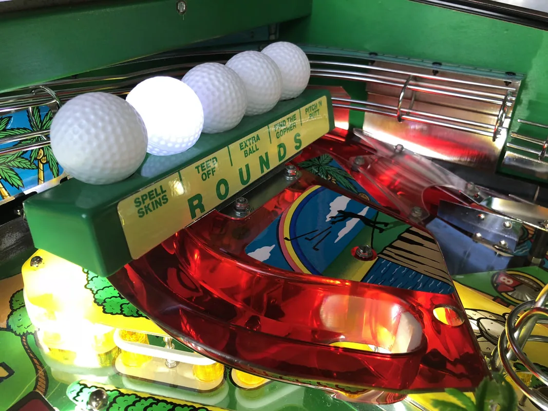
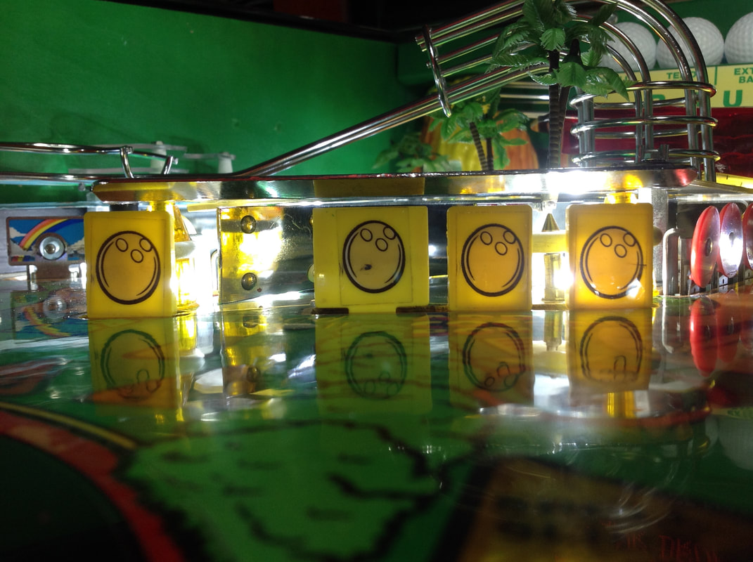
New golf balls installed.


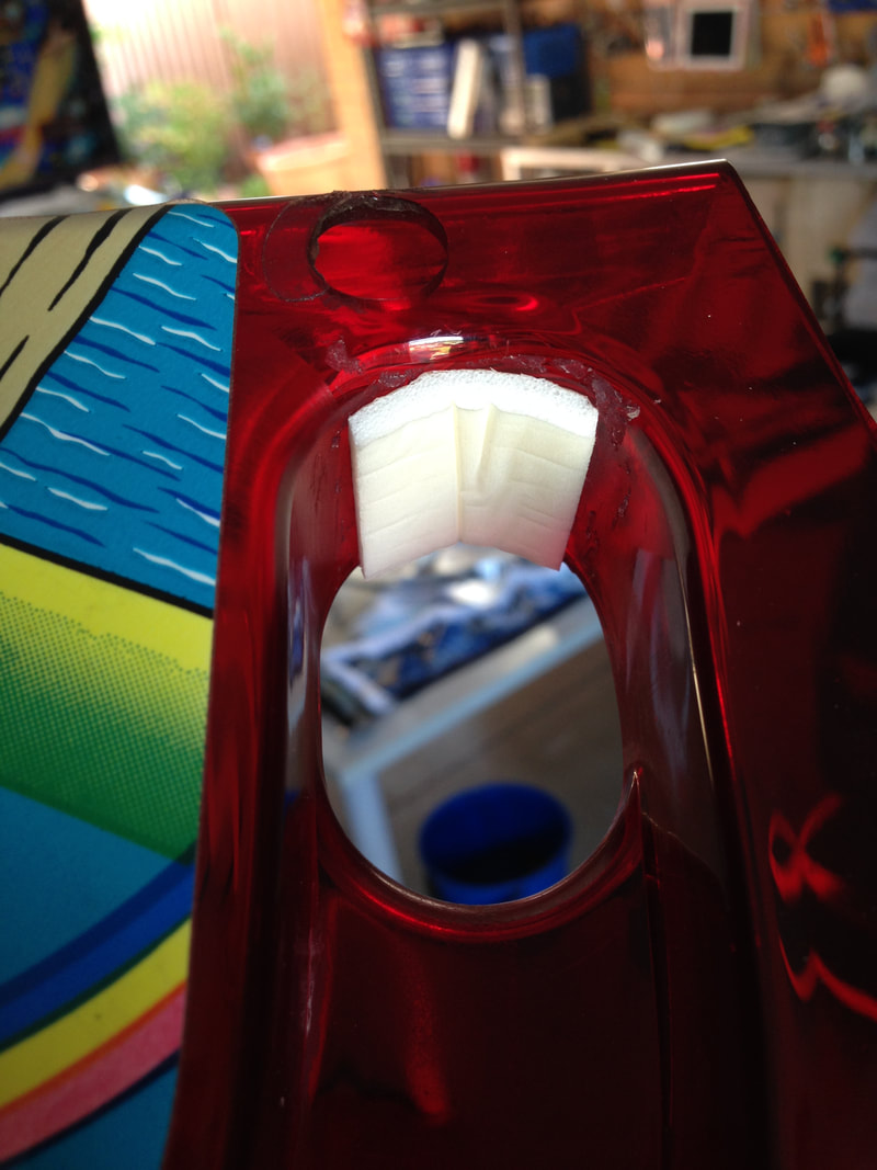
Old rubber bumper that was falling apart and covered in glue.

New bumper made out of weather strip foam. Nice and clean!
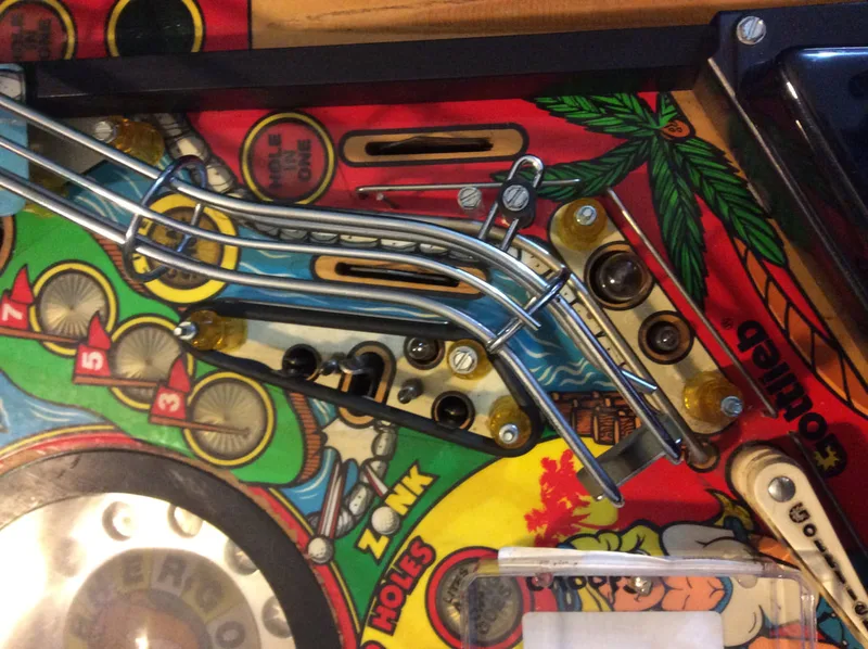
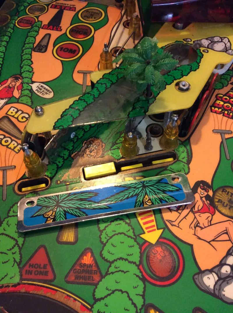
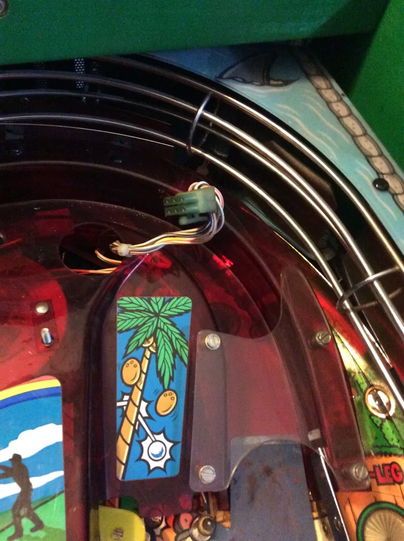
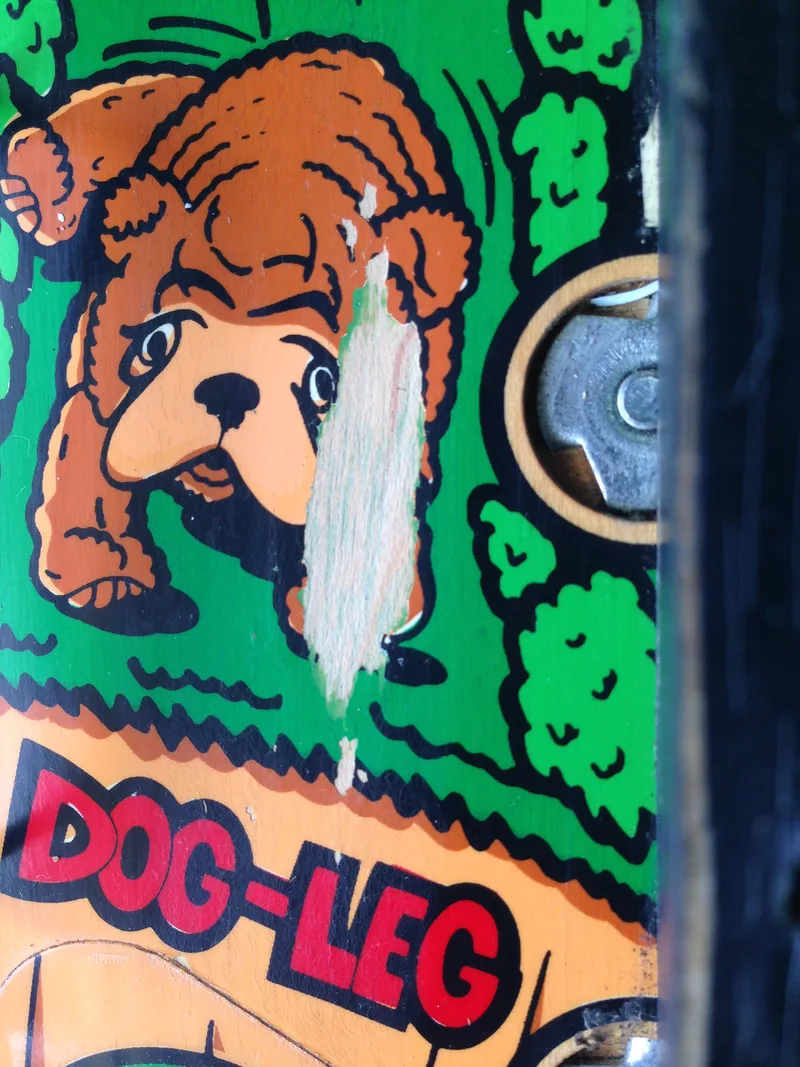
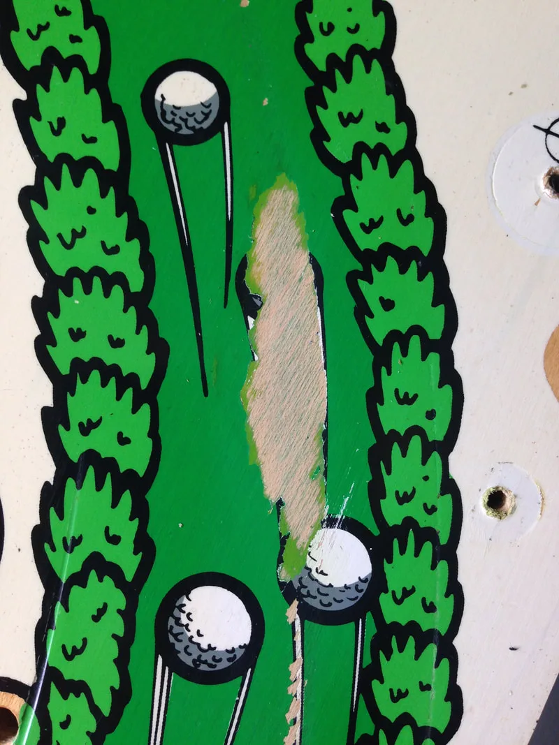
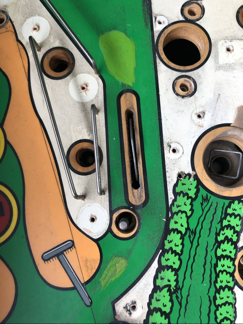
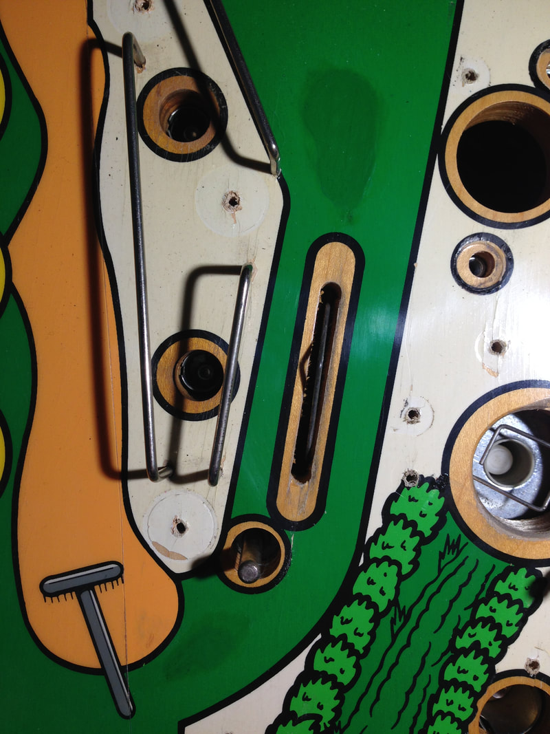
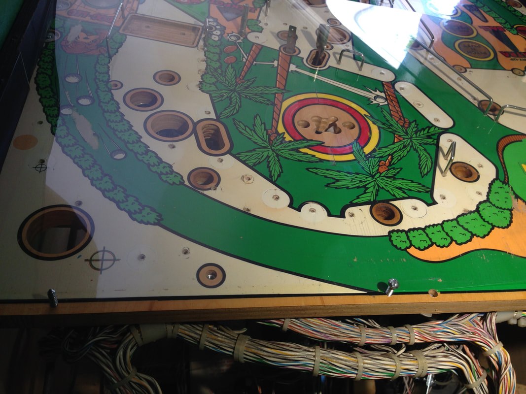
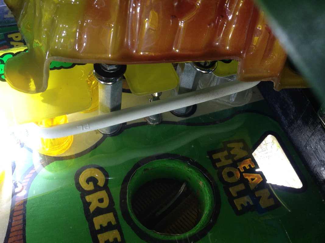
That's because the factory Mylar didn't actually cover the whole playfield. It was not installed in the Mean Hole Green area, the pop bumper area, the area behind the drop targets, and the Dog Leg orbit that loops around to the Mean Hole Green. That's a lot of highly trafficked playfield that isn't protected. No wonder these spots wear down to the wood.
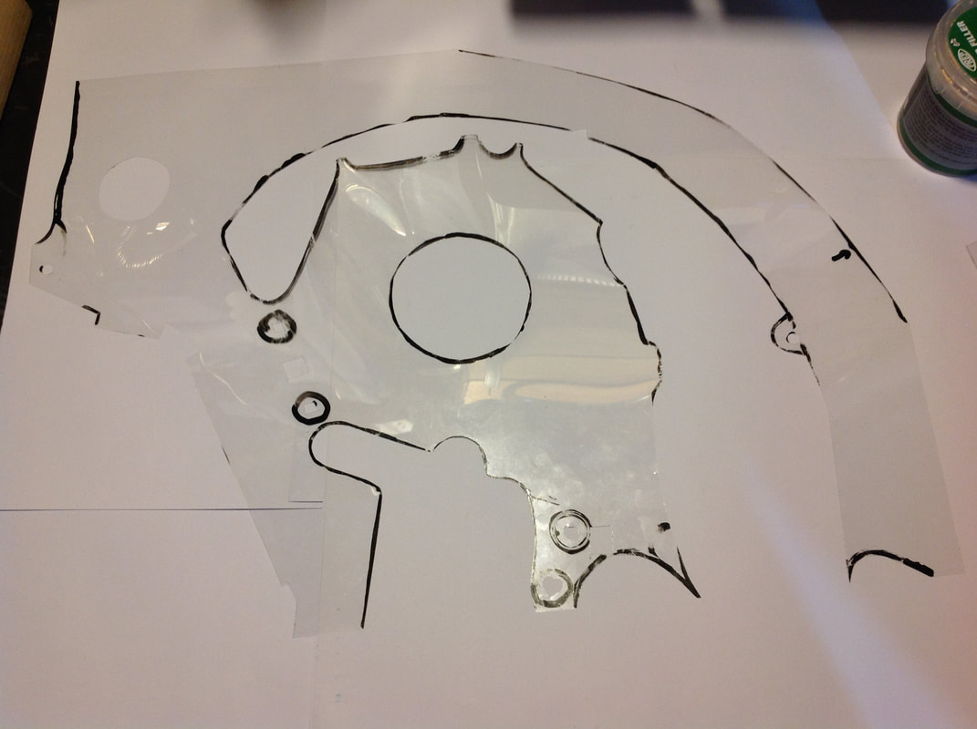
So, I set out to make my own protector. Proper playfield protectors are made out of PETG plastic. Older style protectors were made of Makrolon, while the newer types are cut from Vivak. I couldn't get a hold of either product easily, and I didn't have the equipment to properly cut these materials to size. So I thought I would try with a thinner, lighter material. I had a few sheets of acetate lying around which was easy to lay over the playfield and trace, and could be cut to size with a sharp knife.
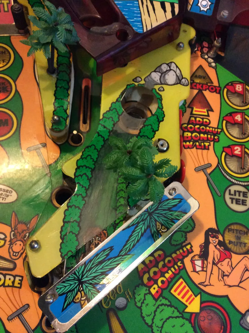
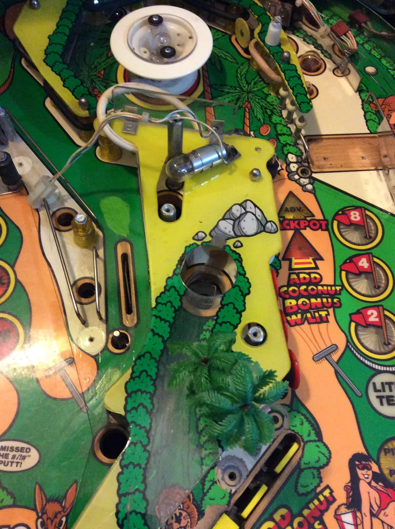
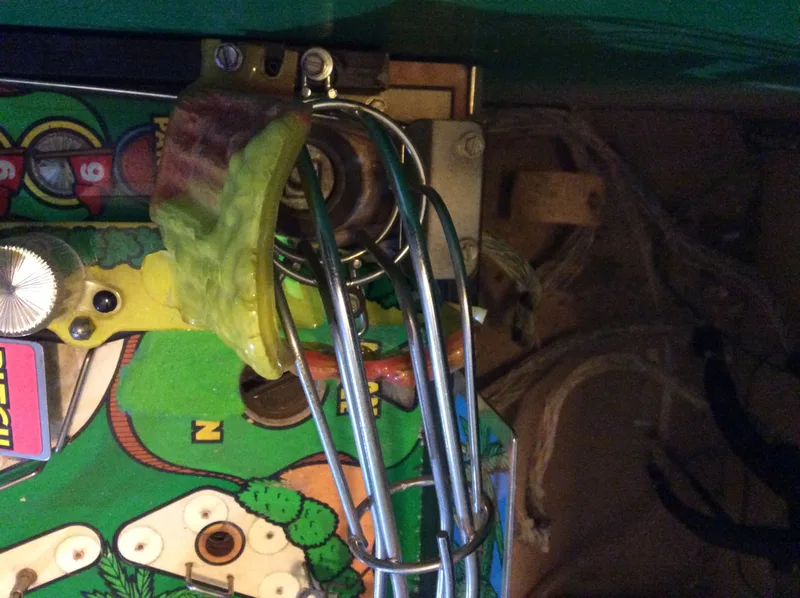
I laid a sheet over the top half of the playfield and traced over the areas I wanted to protect. You'll need to do this with the playfield disassembled completely. It also helps to take out the wire ball guides, but some of these can be tricky to dislodge as the ends are flanged to grip the wood. I used two separate pieces - one to protect the area behind the drop targets, and another to protect the rest of the upper half of the playfield. The acetate sheet turned out to be the perfect thickness; almost identical to the Mylar already on the playfield, which meant there would be no ball tracking issues where the Mylar and protector intersect.

Acetate sheet laid over playfield for tracing.
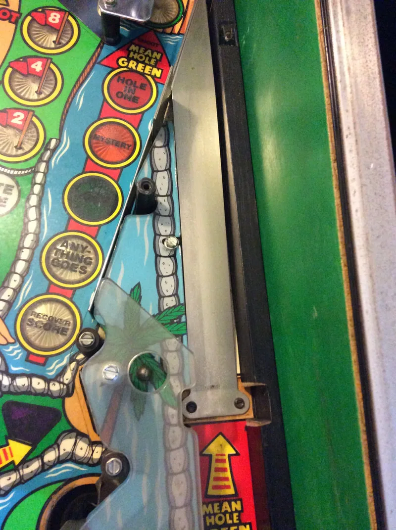
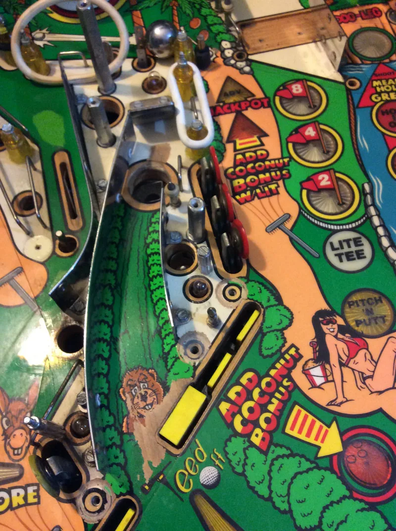
Acetate cut to size to fit the top half of the playfield.
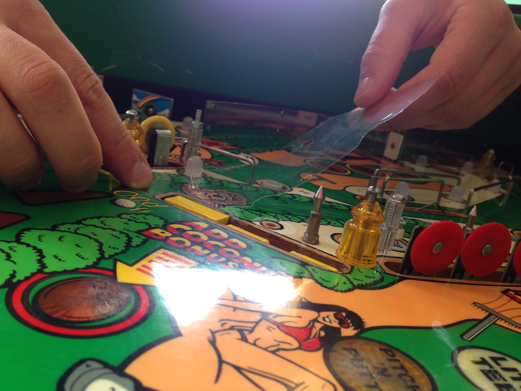
The next step was to clean the trace marks off the protector and check it for good fit. It needed trimming in a few spots until it sat perfectly flat, but when it did, it looked good. The protector floats above the playfield and is held in place but a few posts on the playfield so it doesn't slide around. Working with the acetate was good as it was easy to cut to shape and easy to handle. I'll see how it holds up over time with wear and tear, but I'm hopeful it will at least protect the touched-up areas from further damage.

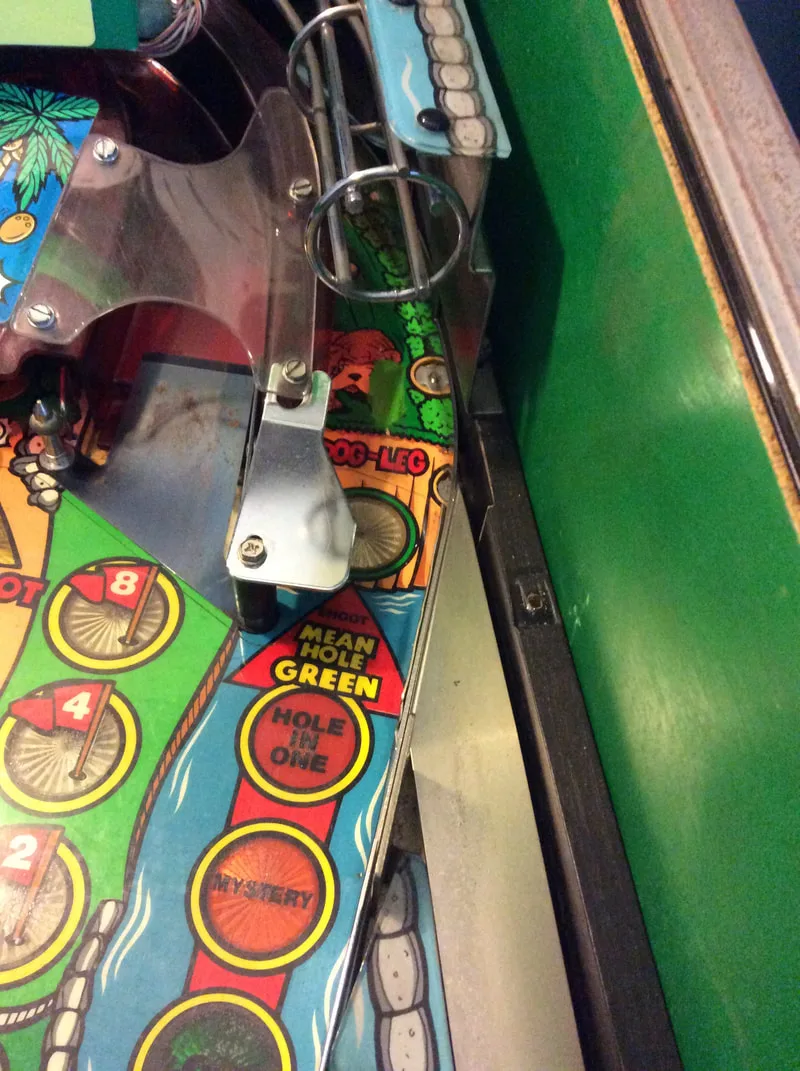
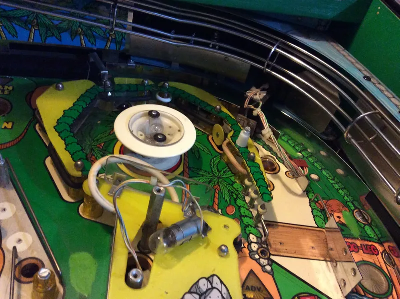
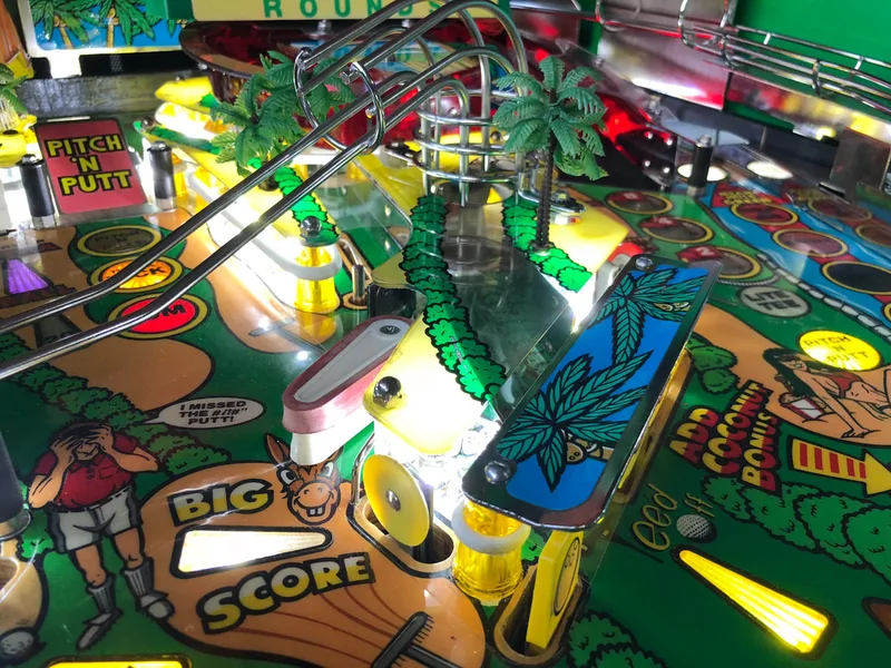
Installation of the playfield protector.
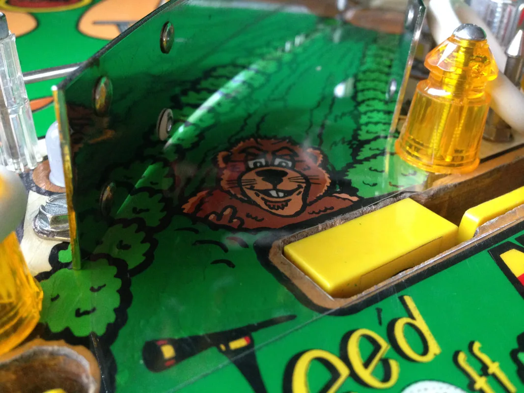
Protector protecting the gopher!

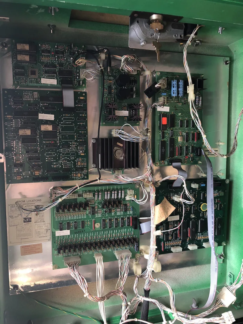
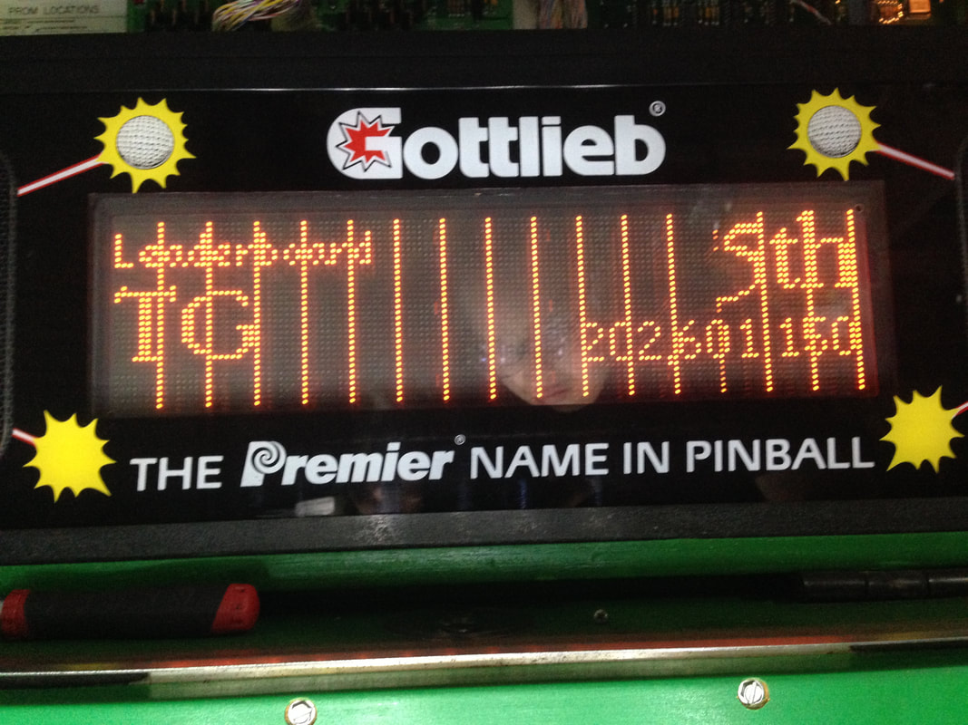
A lot of faults with the System 3 display driver board are attributable to a failed PAL chip at U8. A failed U8 chip often prevents the display from booting, showing a bunch of garbage on the display. However, this wasn't my problem as the display booted up just fine.
Vertical lines appearing across the display.
I had actually encountered a very similar issue before, which was caused by a faulty chip on the display driver board of a couple of my WPC games. So, I had a look at the Gottlieb driver board schematics to see what was what. The main video RAM was held by the chip at U4, so this was the main suspect. This is a 6264 chip, and the same one used by Williams, Bally, Stern, and other manufacturers. Luckily, I still had some spares left over from when I repaired my WPC display driver boards. So, I cut U4 from the board, cleaned the solder joints, installed a socket, and inserted a new 6264 chip.
Looking into the issue more deeply, I found that U13 is also involved in the circuit. U13 is a data multiplexer that basically selects one bit (out of eight) to signal a lit display pixel. Funnily enough, the permanently lit columns were eight columns apart. So, potentially, one of the D0-D7 inputs at U13 was not working properly, causing it to send a signal to light every eighth column. So, I ordered a replacement for U13 from the UK. It arrived a couple of weeks later and I repeated the same procedure - removed the old chip, socketed the new one, and soldered the new one in. This time, success! U13 was the problem and the display was now working normally again. This was one of the more complex circuit board issues I've had to tackle so far, and it was a good learning experience.
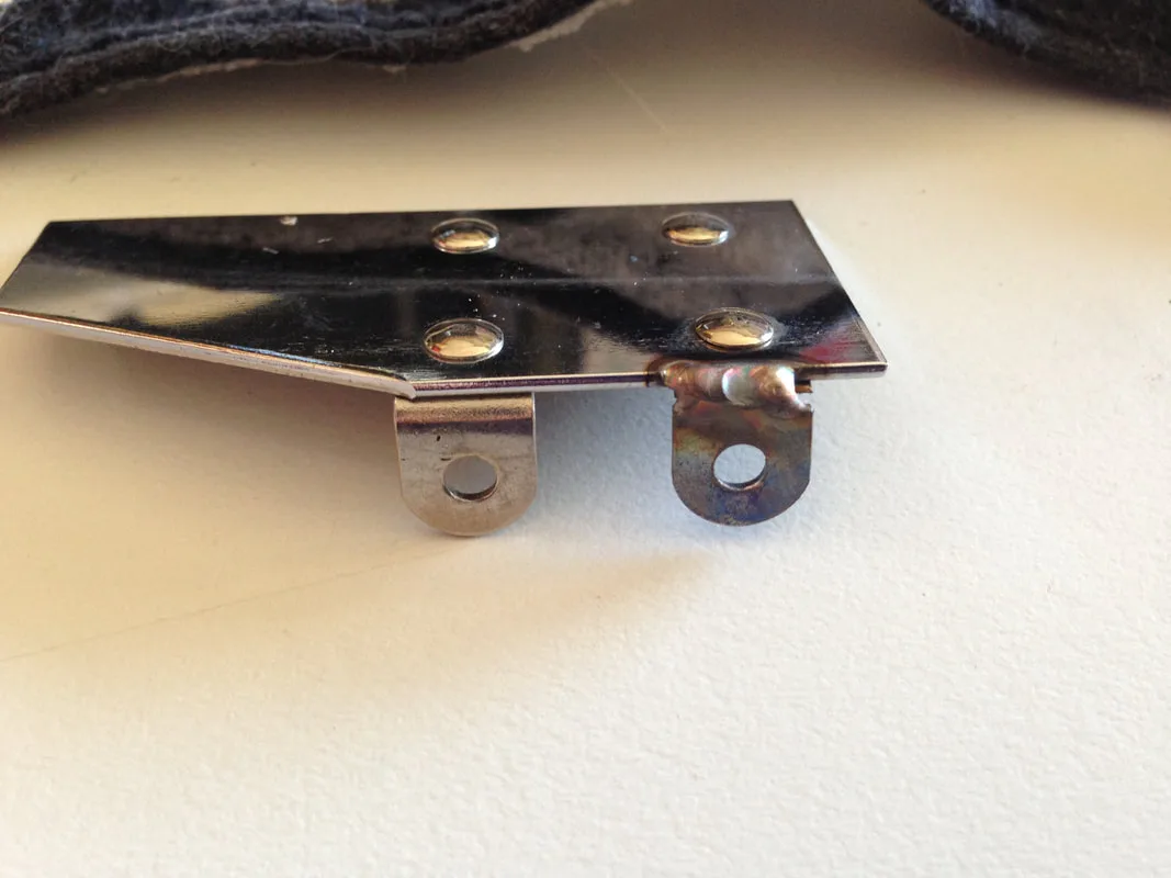
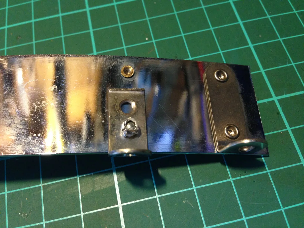
Repaired (rewelded) ball guide tab.
I also had issues with ball guide tabs that had been riveted back onto the ball guide, but could not be screwed into the playfield because the rivet protruded over the screw hole. The riveting was actually a pretty good repair done by a previous owner, however they did not cut down the rivets after snapping them in place. I don't know how they reassembled the game, as the ball guide screws were impossible to insert or remove with the rivets hanging in the way. I used a grinder to grind the protruding rivets down, and then smoothed the edges out. I reduced the protrusion enough that the screws could be inserted at the proper angle.
Rivet protruding out over the screw hole tab.
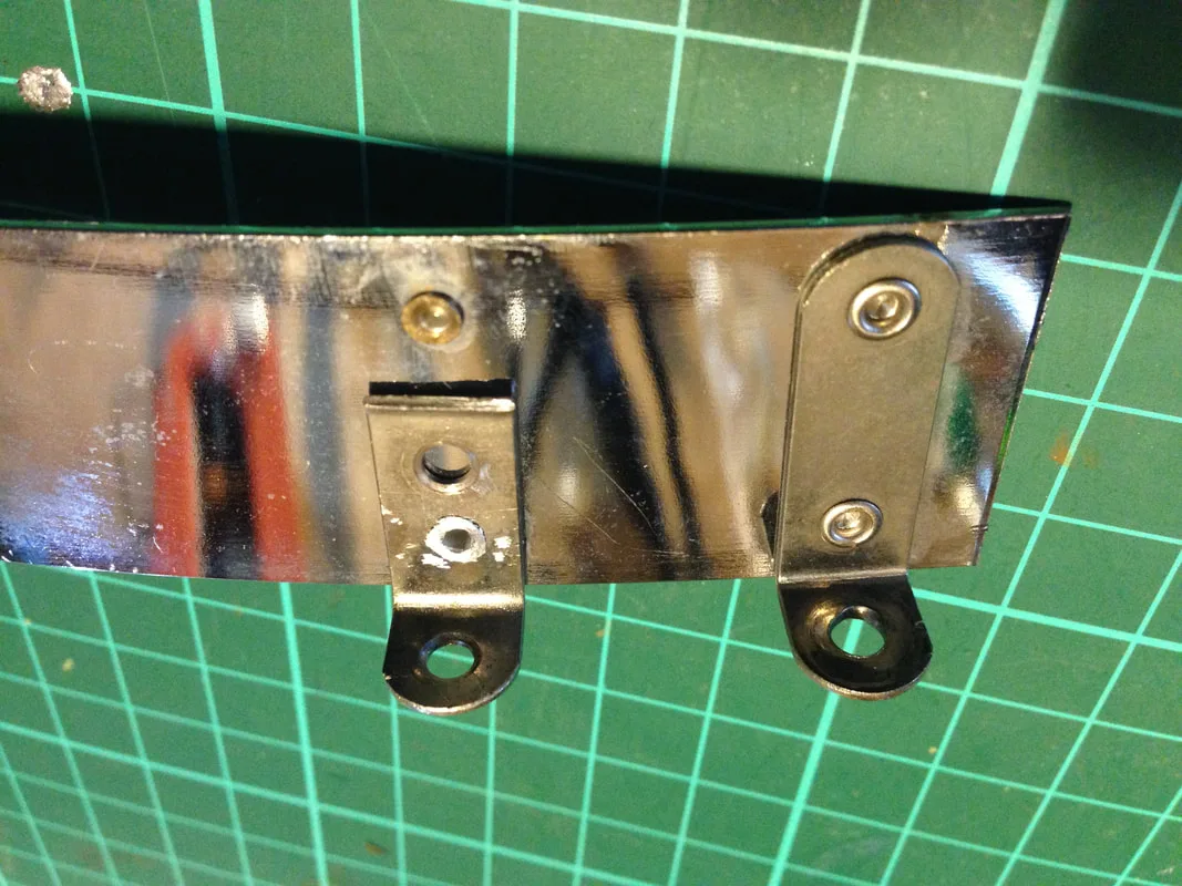
Rivet ground down and flush with the ball guide.

I opted to repaint the wood with a gloss black paint and then covered this with a couple of coats of clearcoat. The finished product does look a little different from the other vinyl-wrapped ball guides on the game, but as it is at the very back of the playfield, I don't think it matters. The gloss paint and clearcoat gives it a glossy look, which would look pretty good on the other timber ball guides, too.
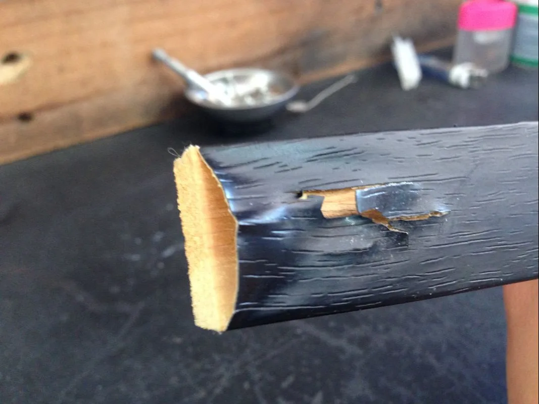
Damaged timber ball guide.

Repainted and reinstalled on the playfield.
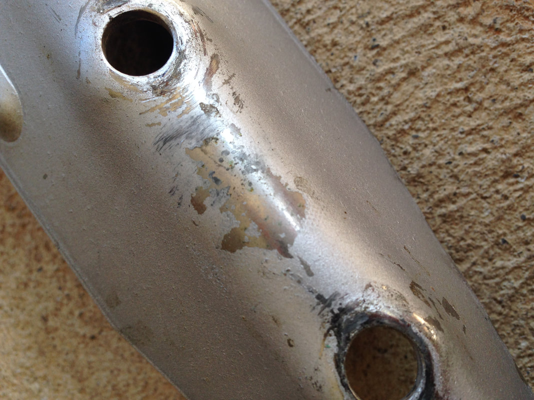
The paint came off these legs without too much trouble after applying some paint stripper. It then became clear that the legs had been painted because they had started to rust. There were rust spots covering most of the legs, which was a shame. After stripping them of paint, I soaked them in my vinegar bath for about 24 hours. This removed most of the surface rust and loosened the rest of it to the point that it came off easily. I polished the legs up with some steel wool and rinsed the vinegar off at the same time. I found that, for some reason, these legs started to rust again within minutes (!) of being rinsed off. I have no idea why they started to show rust again so quickly, but there was a noticeable difference between when they were first rinsed off to a minute later. I dried them off as quickly as possible and gave them another polish with fine grade steel wool. Some of the rust pits were still visible but there wasn't much that could be done about this. Thankfully, the shine of the chrome came up well, which was the main thing. I gave the legs a couple of coats of clearcoat to protect them from rust in the future and cleaned up the leg levellers. The leg bolts got a good polish as well. I think they turned out well!
Legs covered in spray paint with chrome showing underneath.
Paint stripped, rust removed, and coated with clear.

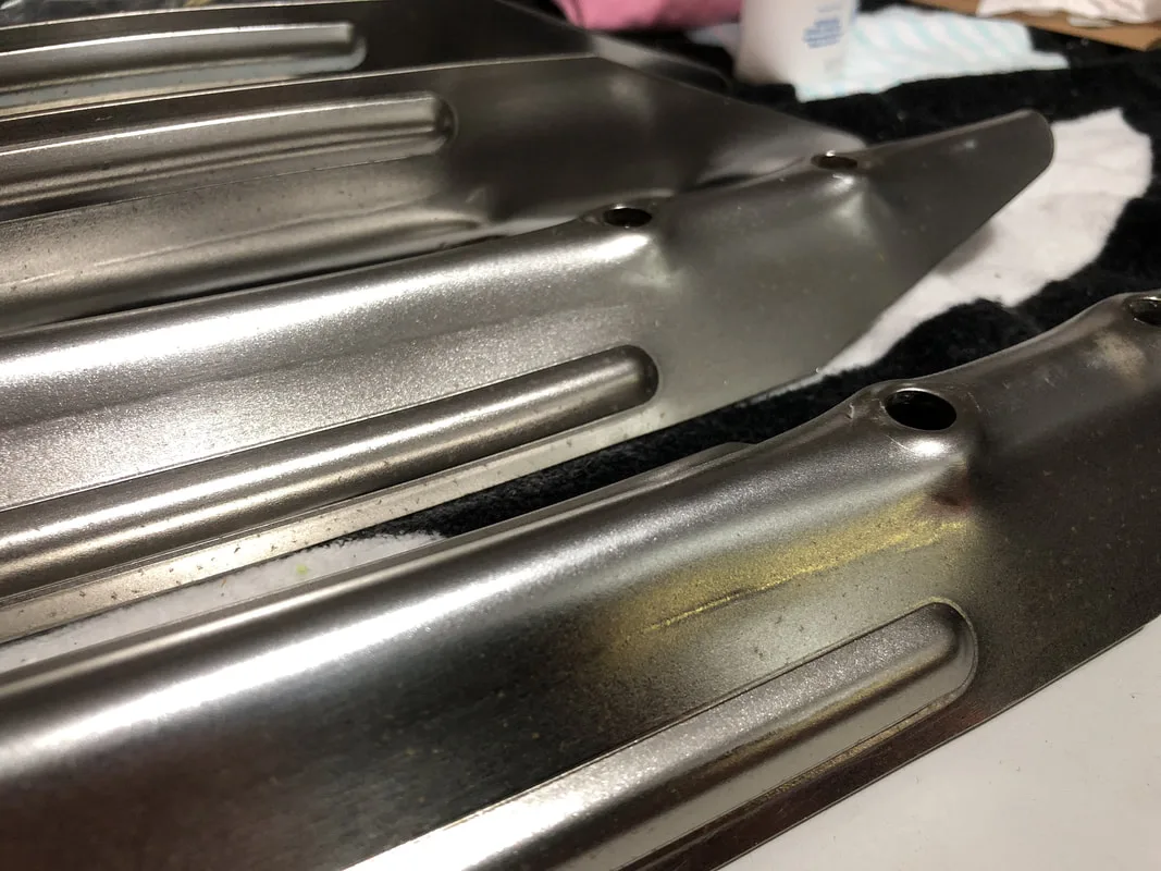
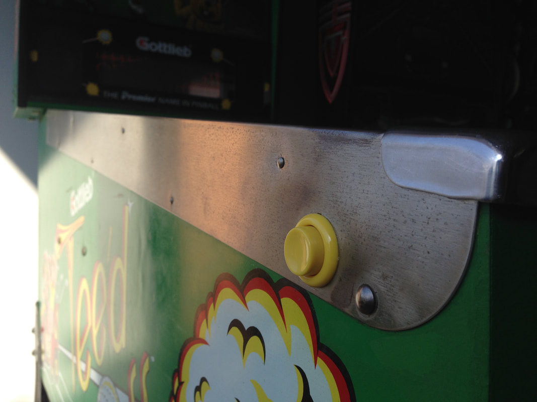
I just hit them with a long polishing session with ultra fine steel wool. This worked really well and removed all of the rust, which turned out to be mostly light surface rust. They polished up reasonably well, but they were still a little rough to the touch, and spots where the rust had penetrated deeper were darker.
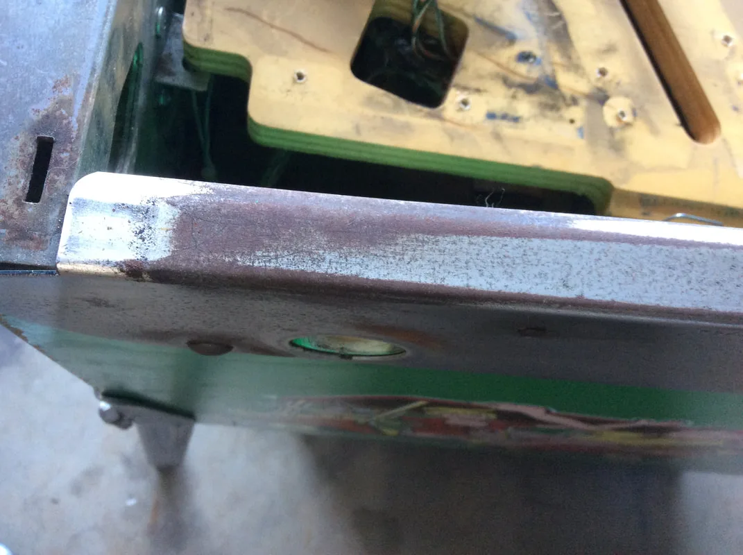
Rusty side rails!

Rust polished away. Nice and smooth now.
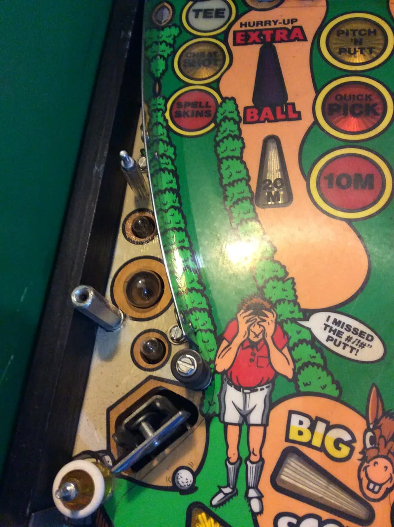
So, I bought a new set of shiny rails from Jeff. Removing the old rails went quite smoothly. Vid has a relevant guide on how to do this. I used an old but sturdy plasterboard scraper, hammered under the heads of the nails to raise them up a bit, followed with a twist and pull from a pair of flush end nippers/cutters to remove the nail. It took about 10 minutes to do each side. I affixed them with a couple of rows of adhesive tape (Bunnings).

Original side rail, left side.
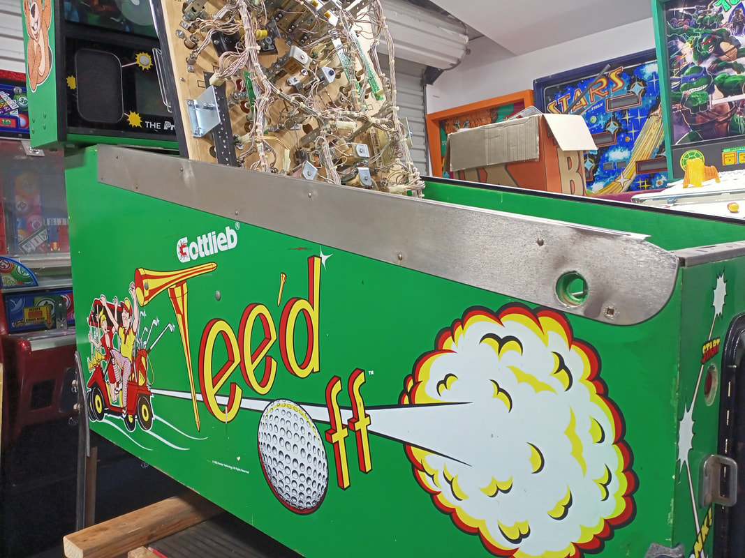

New side rail installed, left side.
I also polished the lockdown bar and metal trim at the top of the playfield glass on the buffing wheel using a sisal polishing wheel. The lockdown bar took an hour to bring to a modest shine, but I think it looks quite good. Not quite a mirror finish, but much nicer than stock.
Metal glass channel polished.

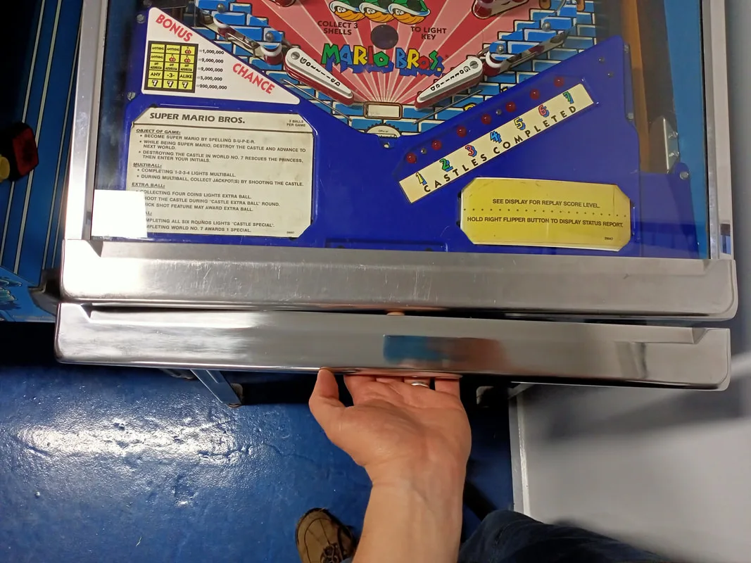
Polished lockdown bar compared to an original on Super Mario Bros.

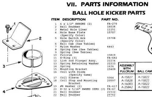
Manual excerpt with the liner part identified.

Liner installed after modification.
This flasher was controlled by Q15 on the driver board and sure enough, the MOSFET tested bad. I whacked a new IRL540 MOSFET in as recommended by Clay's guide and the flasher worked normally again. Easy!

Dead flasher under the centre ramp.
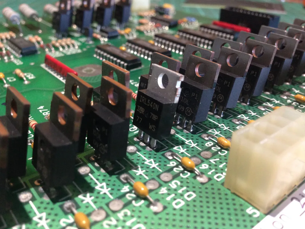
New MOSFET installed at Q15.


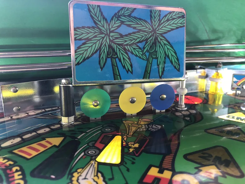
Original rubber placement

Improved rubber placement

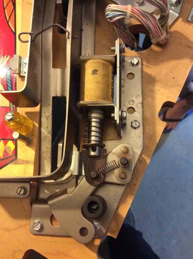
Broken hold winding on flipper coil.
Even after fixing this problem, the left flipper would occasionally stay engaged even after the cabinet button was released. This was due to a sticky switch contact, which had been destroyed by arcing across the contacts (remember, System 3 flipper switches have high current contacts that carry 50 volts through them). The pitting of the contact had created a groove which sometimes caught onto the other switch blade, holding the two blades together. Sanding the contact down with a file helped alleviate the issue until a new switch arrived to replace the old one.
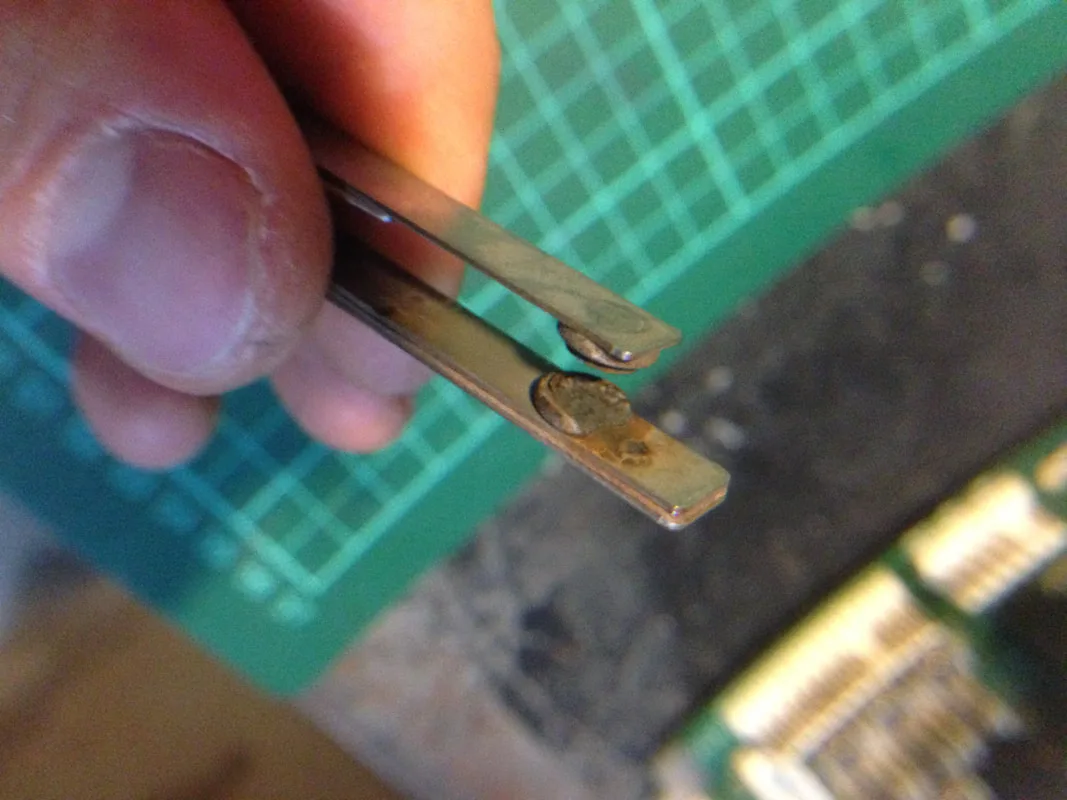
Pitting of the flipper switch contact.


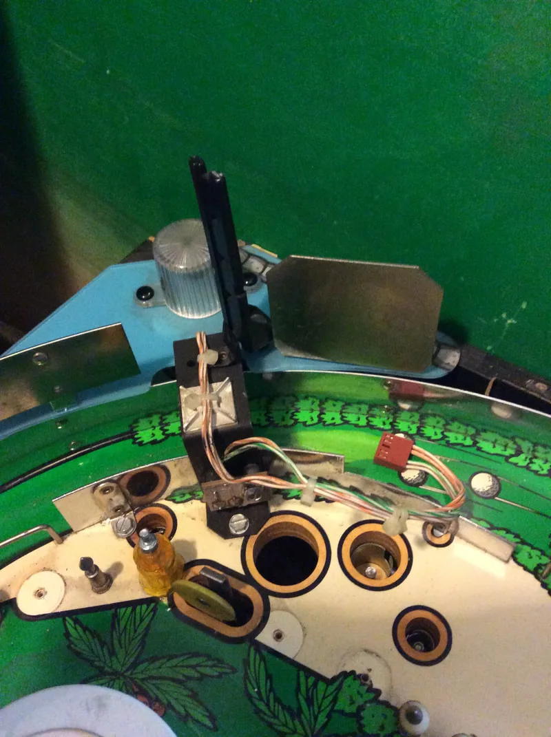
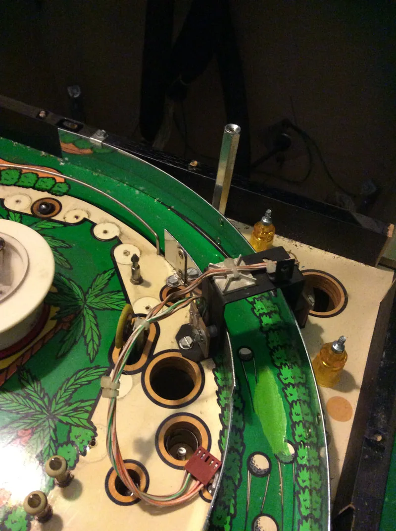
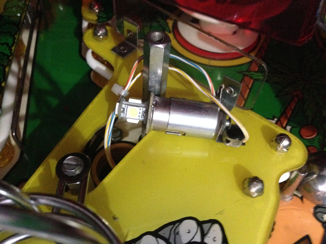
Opto boards underneath the playfield with connectors installed.
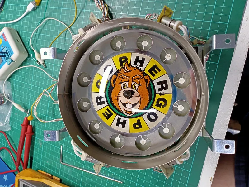
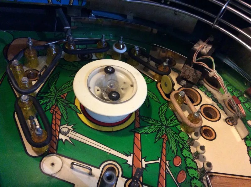
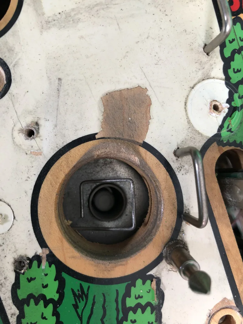
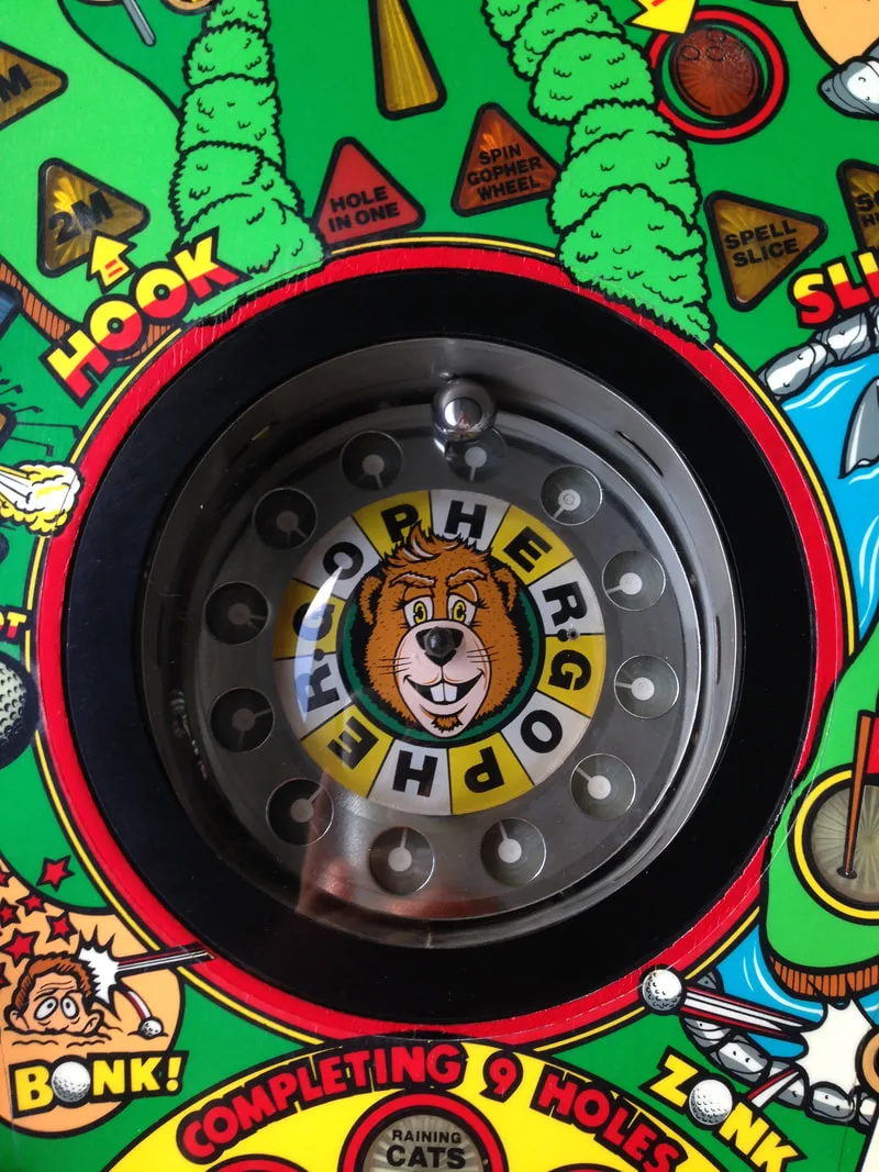
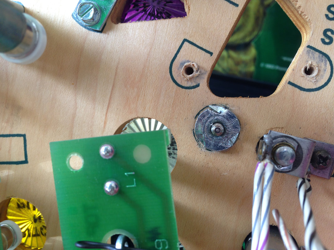
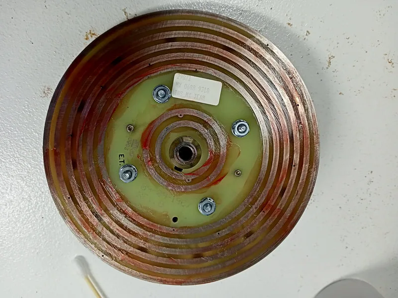
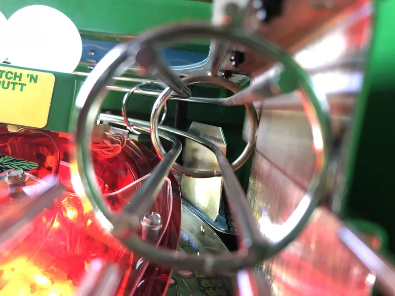
Gopher wheel removed for servicing.

The wheel plate needs to be removed from the assembly to provide access to the switches underneath. Loosen the grub screw that fastens the wheel to the motor shaft, and lift the wheel off the shaft.

Grub screw that fastens the wheel assembly to the motor shaft.
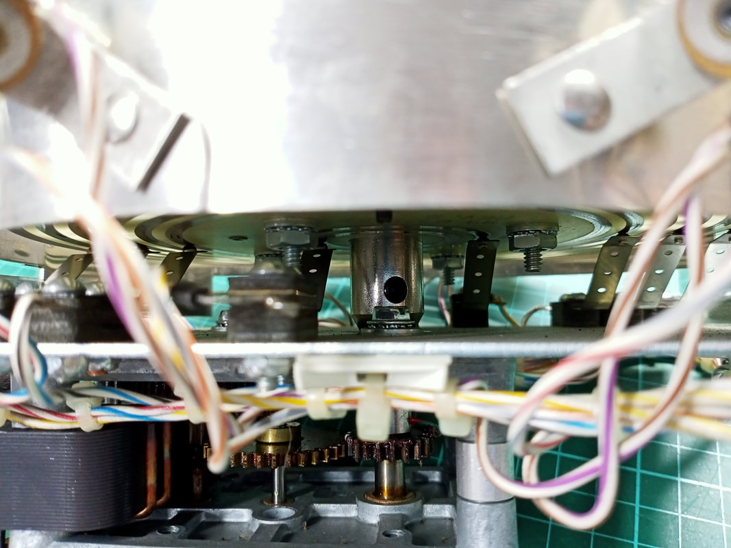
With the wheel off, I was able to inspect the switches in the assembly. They are actually common leaf switches, which are connected to conductive tracks on the bottom of the wheel plate, which connect to each of the letter positions on the wheel. It's a clever way to implement the feature, but it relies on moving parts. It's very similar to a stepper assembly from an electromechanical pinball machine such as those used for score units, bonus units, and similar. Specifically, it relies on metal-to-metal contact, which I suspect was contributing to the screeching noises when the wheel spun around.

Underside of the wheel.
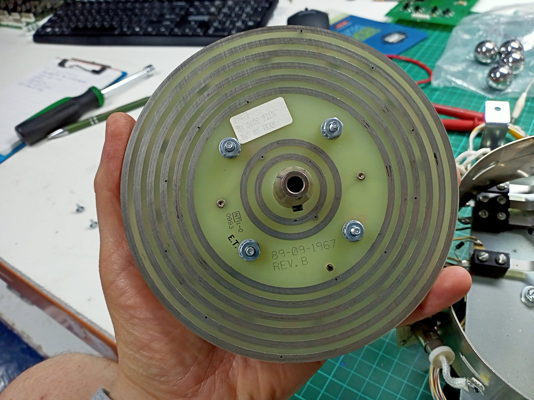
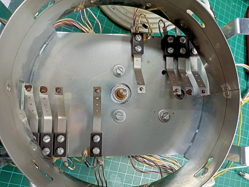
Switches for each of the letter positions under the wheel.

Each of the switches appeared to have the appropriate tension, and was positioned properly on the correct track under the wheel. However when I took a closer look at the switches, I could see that some of them were covered in crud that was potentially old, dry grease. This would definitely contribute to issues with switch registration, so I cleaned them all off and gave them a light polish with a cleaning rag until they were nice and shiny again.
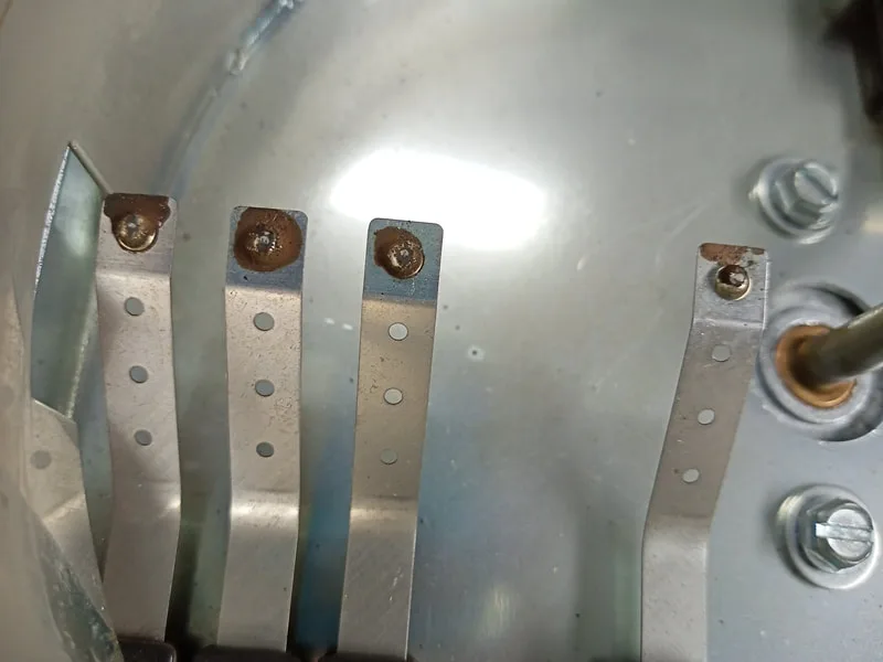
Switches with dried grease and dirt on the contacts.

Switches after cleaning.
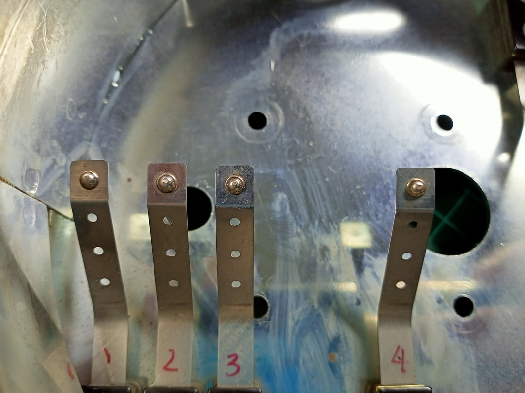
As these switch contacts would be running along the metal tracks of the wheel, I added some PTFE grease (Supercheap) to the switch contacts as well as the wheel tracks to ensure that they were lubricated.
Lubricating the tracks on the wheel.
I also took this opportunity to apply some new grease to the gears of the motor itself, as they appeared to be minimally lubricated. I didn't bother disassembling the entire gearbox for this as it had an open casing and I was able to clean most of the old grease out and apply new grease without taking it apart. I put everything back together and the gopher wheel ran like a DREAM! Whisper quiet; you could barely hear it spin. This was a big improvement, and as an added bonus, I had also fixed a couple of the letter positions registering intermittently. This was probably an alignment issue, or poor contact issue, between the switch contacts and the underside of the wheel.
Of course, heed the warning on page 22 of the manual regarding the Smart Switches. Don't get too rough with them when removing them from the playfield or cleaning them, as moving the switch blades can prevent the switch from working. They're expensive to replace!
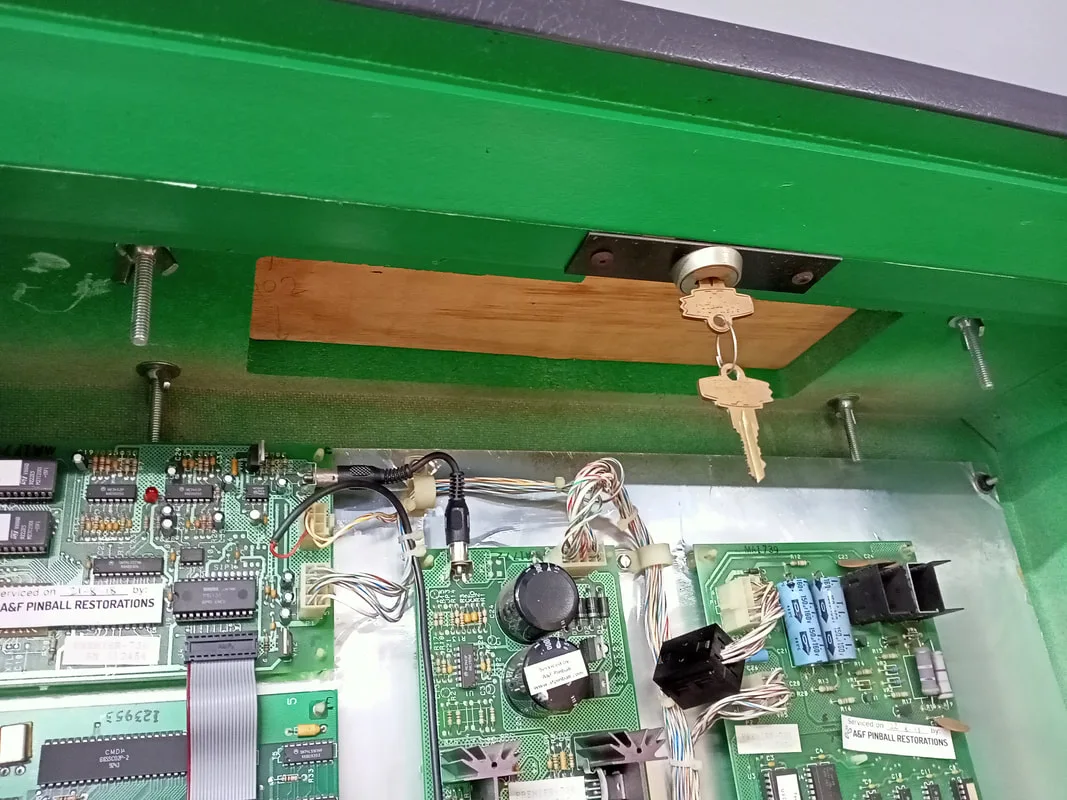
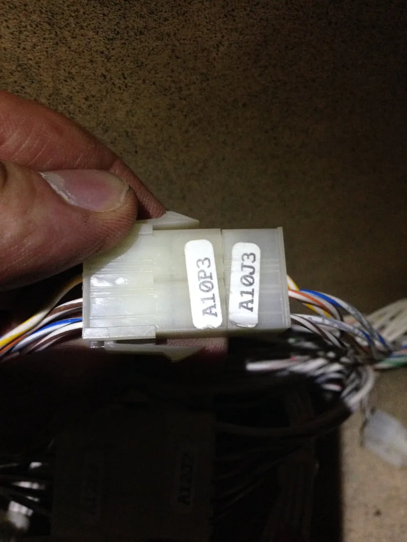
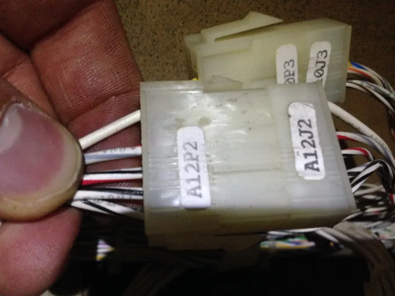
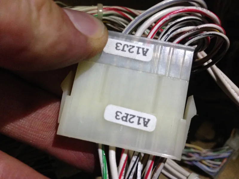
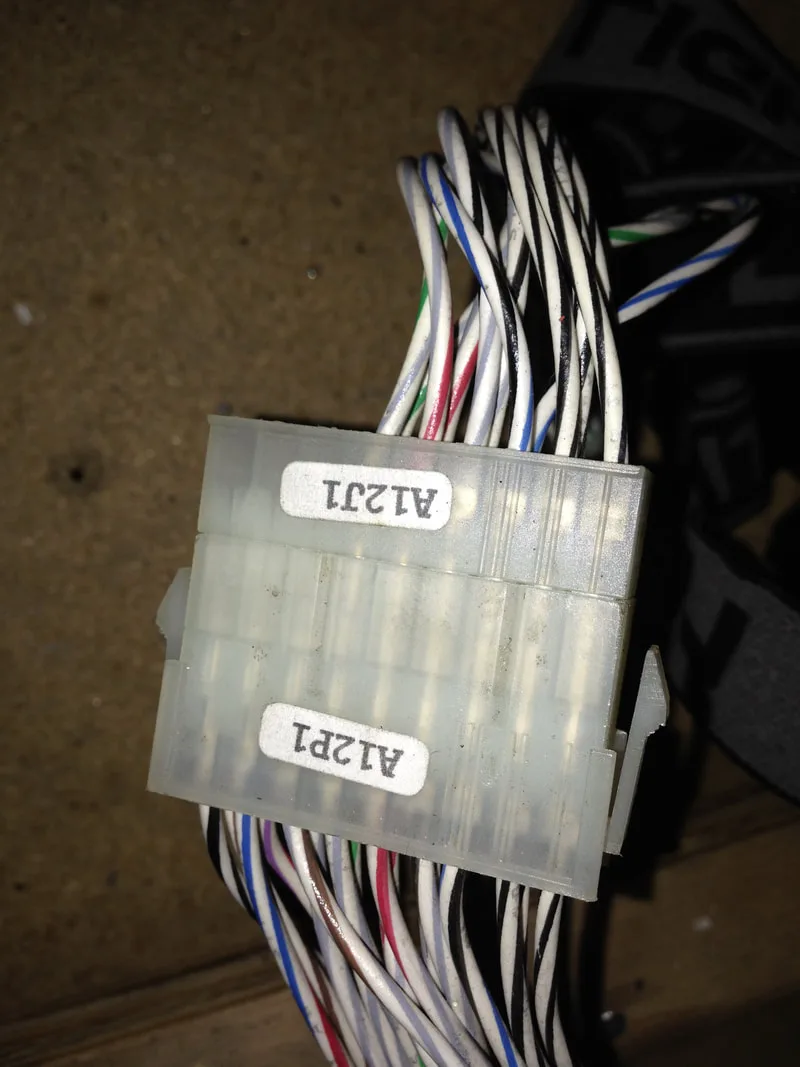
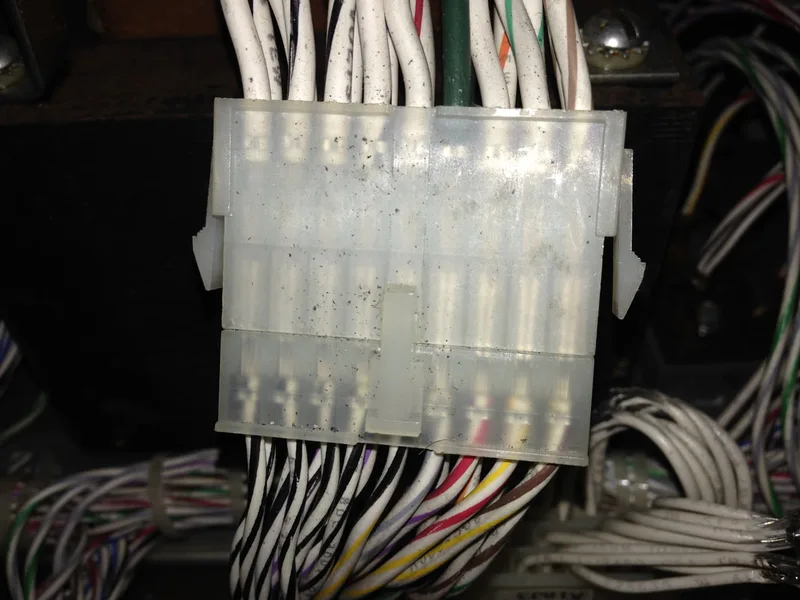
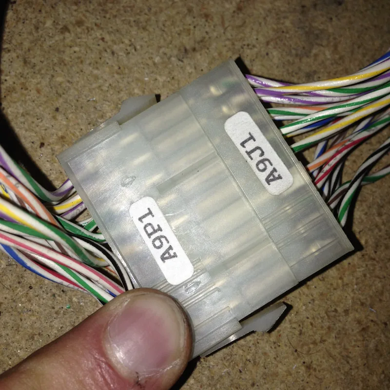
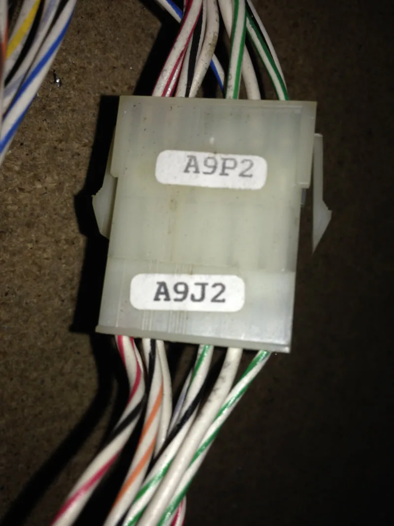
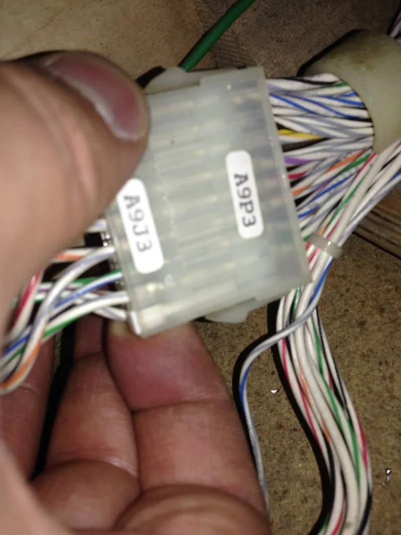
Another thing to be mindful of when reconnecting the playfield and transformer wiring is that the labels attached to the connectors often fall off so it is difficult to tell which connectors go where. For the transformer and cabinet connectors, I took some reference images from a friend's Stargate (Gottlieb, 1995) to compare to my own game and match up the wiring colours; see below. This helped a lot when reconnecting my own transformer.
For the backbox connectors, Clay's Repair Guides include a list of each connector and the jacks they connect to, ordered by wire colour. Very handy for double-checking your work before powering the game on. When double-checking against the values in Clay's list, I found that I had mixed up a connector between the power supply board and CPU control board. It would not have been good if I turned the game on before checking my work! So, be patient, and check your connectors carefully.
As for upgrades, I fitted the game with white 4+1 LEDs for the general illumination and backbox lighting, and white flat top LEDs for the inserts. I opted to go for plain white in this game as there were a lot of different colours on the playfield inserts which I either did not have or couldn't justify ordering in small quantities. Doing it this was is actually a lot easier and I will probably be LED'ing games in this kind of fashion in the future. The main difference is that some inserts will be brighter with plain white light at the expense of deeper colour. Bright inserts work well on Tee'd Off, so the final result looks good.
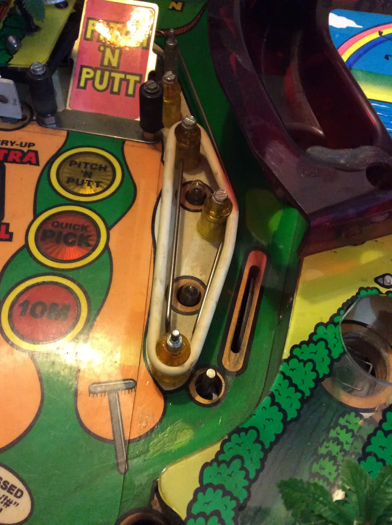
Post sleeves were replaced with new ones and all rubbers were replaced with new white rubber rings as white seems to suit Tee'd Off quite well. There are a lot of rubber rings at the top of the playfield, particularly around the pop bumper. The upper playfield was covered with my custom acetate playfield protector which should protect all of the repaired areas into the future.
Unfortunately, there isn't much in the way of custom instruction cards available to suit Tee'd Off. The stock standard cards on my game cleaned up quite well and new ones are available to download and print (Pinball Rebel) in case the originals are too far gone.
Conclusion
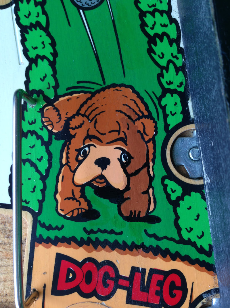
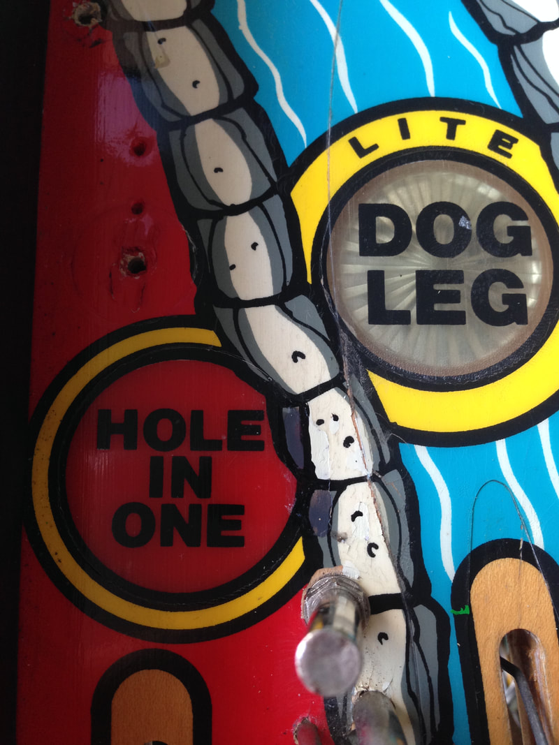
My first Gottlieb System 3 restoration went well. It took a while - almost a year - from go to woe, but the end result was better than I expected it to be. I'm particularly happy with the touched up areas on the playfield. It's difficult to see that they were ever worn at all, and a couple of areas, like the dog leg and gold balls on the dog leg, are hardly even visible to the player.
The System 3 flippers definitely have a different feel to Bally/Williams and Data East games. They seem a bit more "flappy", for lack of a better word. But the main thing is that they're strong. A flipper rebuild works wonders on these assemblies.
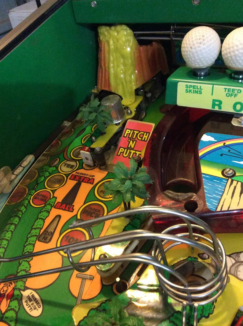
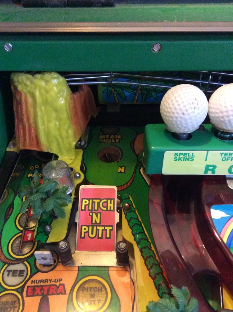
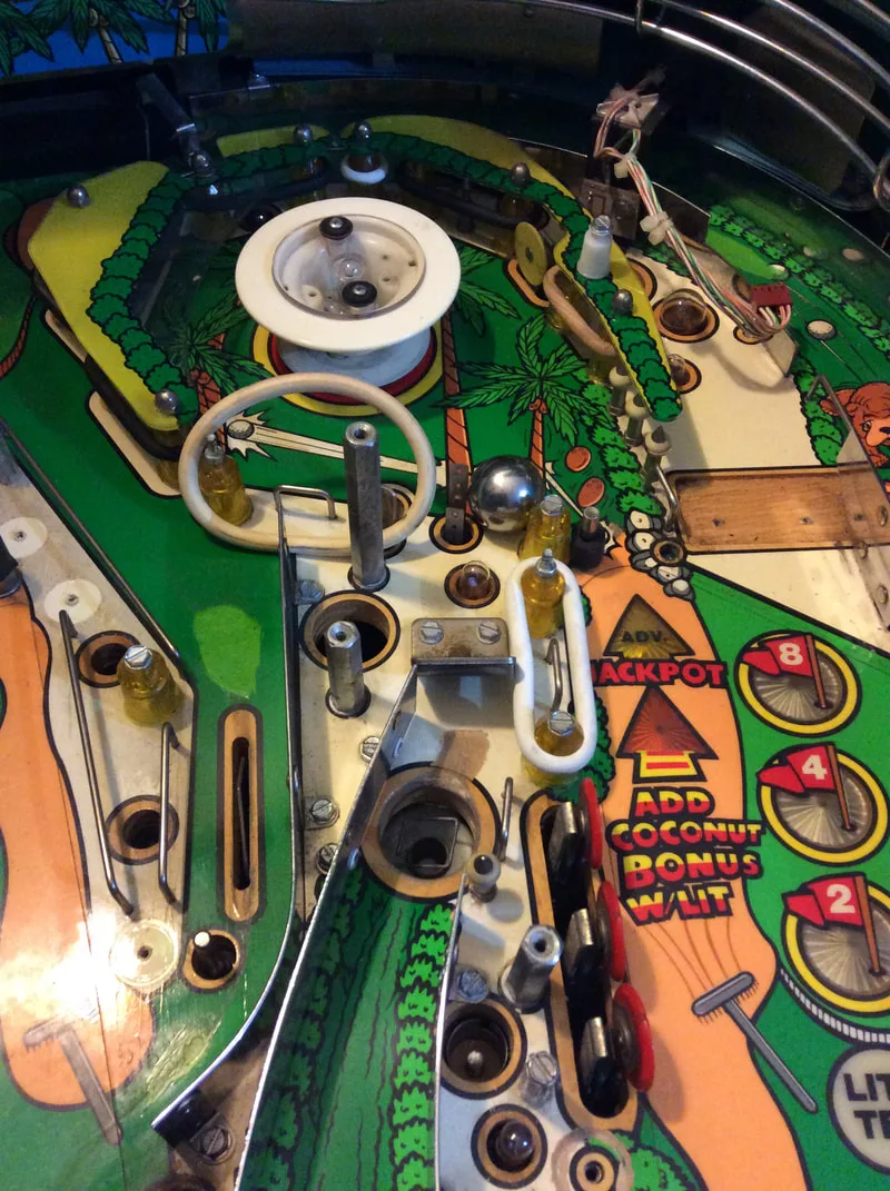
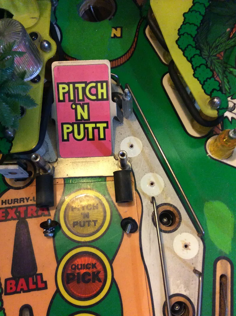
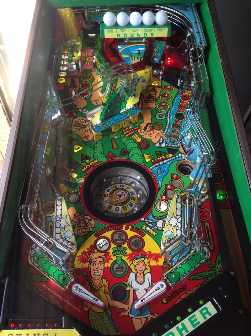
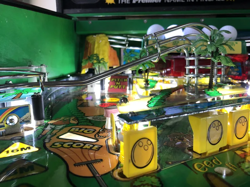
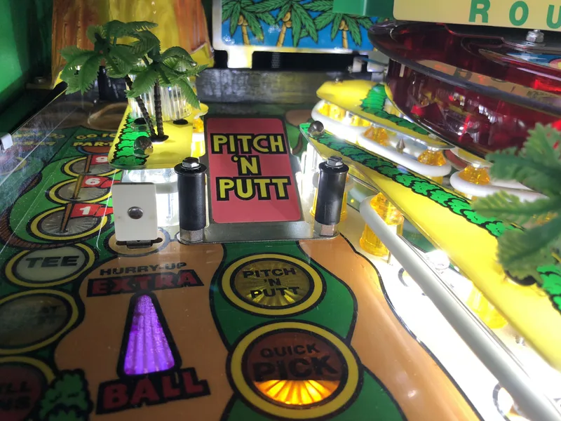
With working flippers, working lights, working coils, and a clean playfield, Tee'd Off is a lot of fun to play. A lot of people seem to diss System 3s and pass Tee'd Off for a No Good Gofers (Williams, 1997) ripoff, but the gameplay is actually quite fun. The Pitch 'n' Putt is a fun shot to aim for, and the gopher wheel is a cool gimmick. The only thing that detracts from the game is the gopher's endless taunting and callouts. They do get tiresome after a while. Even in attract mode, the game makes callouts every 20 seconds or so. So if you're easily irritated by repetitive sounds, turn the volume down! Other than that, I hope I get the chance to work on other System 3 games in the future and perform more board repairs, in particular. Fore!


Unfortunately I don't have any photos of those specific parts of the topper. I might be able to get some for you, though. I will let you know!
Alex