|
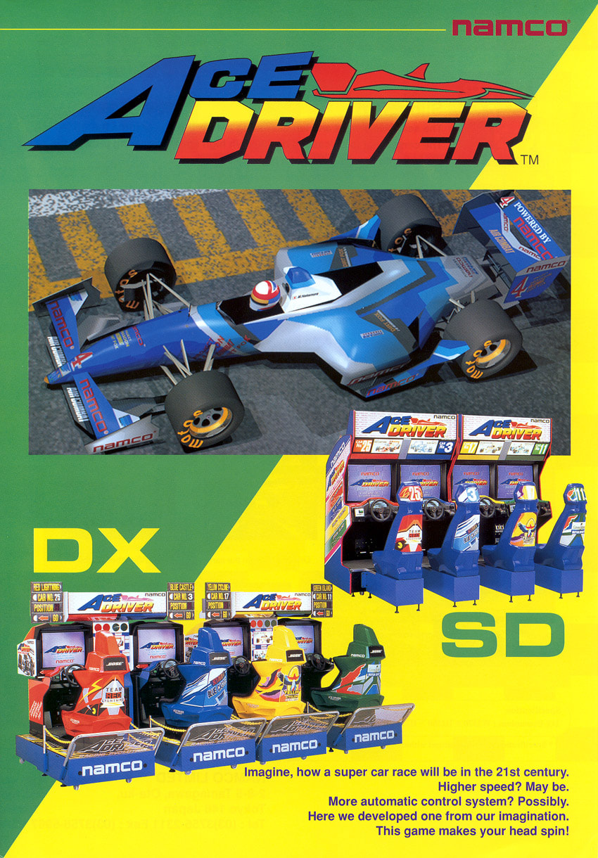
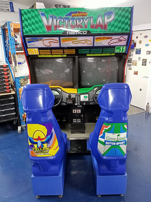
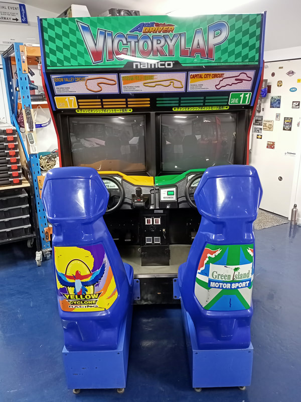
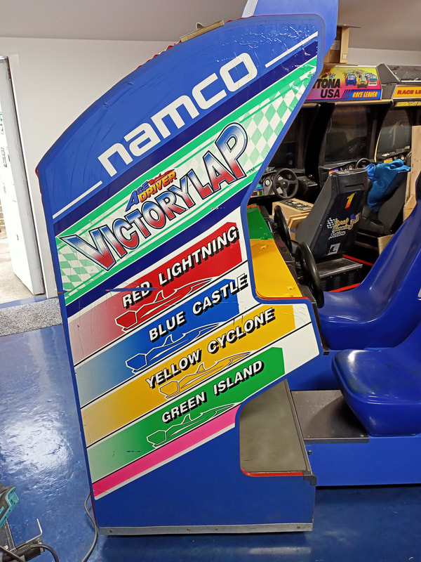
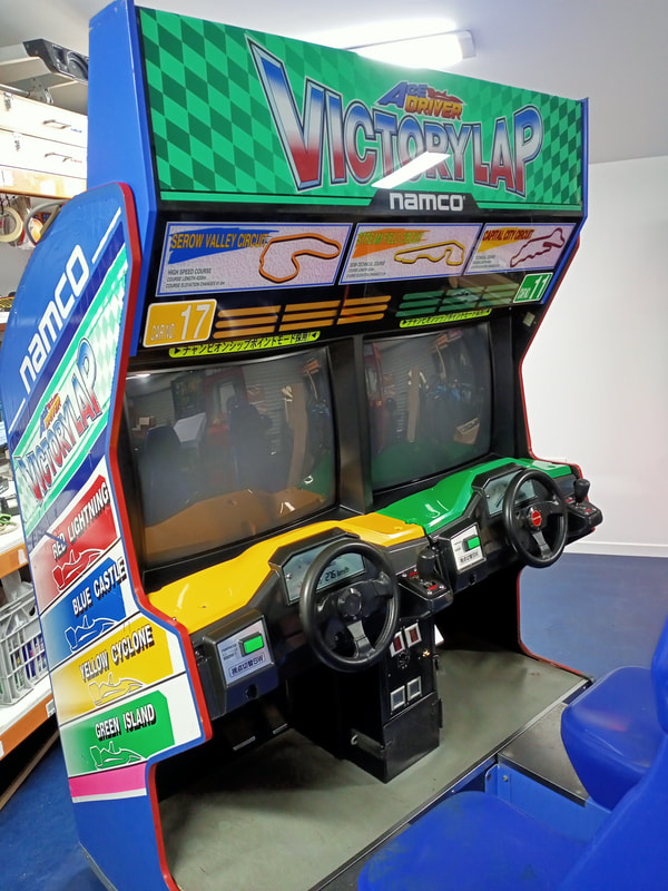
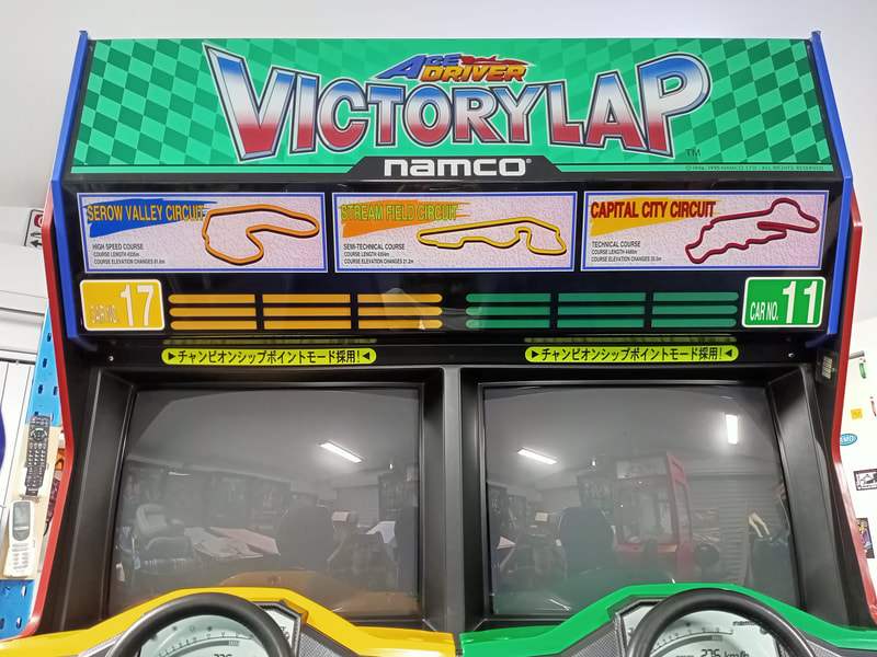
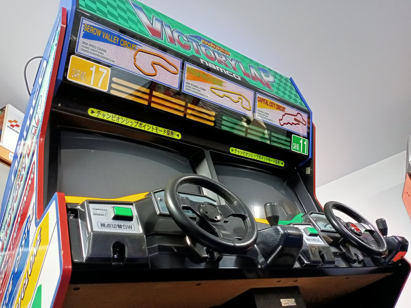
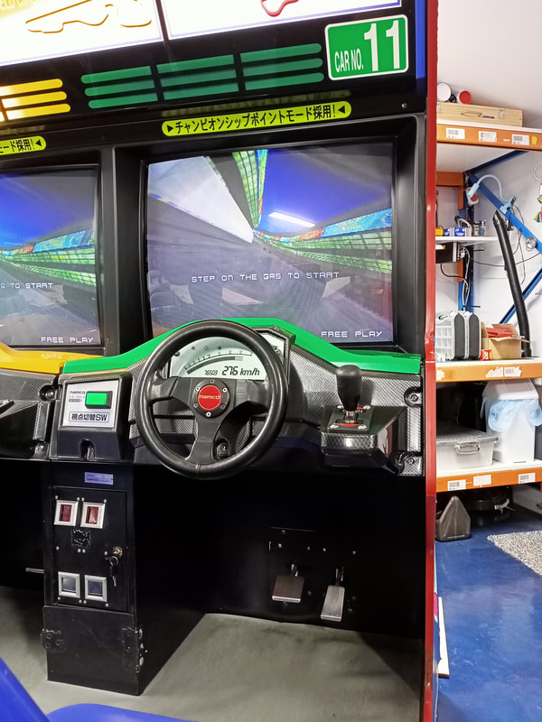
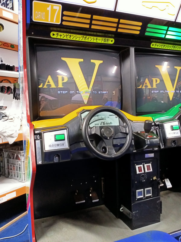
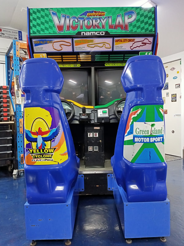
This is starting to look like a video arcade restoration blog rather than a pinball one! However, I am running out of space with too many projects sitting in the queue, so I need to sell some games to make space. Naturally, that means the larger games, particularly the twin driving cabinets, have to go! It hasn't been too long since I finished with my Cyber Cycles restoration, and now, I'm onto another Namco game. This time it is Namco's Ace Driver: Victory Lap (1996). It might be a little confusing why I have two game flyers at the top of this page. One for Ace Driver, and another for Victory Lap. That's because Victory Lap was not a complete, standalone game. It was sold as a conversion kit for the original Ace Driver (1994), and used the same cabinet and hardware. This restoration was mainly a cabinet tidy-up and go-over, as the game was mostly working when I first powered it up. Initial condition report (click on sections below to view details) Cabinet
Poor condition overall.
Internals
Average condition overall.
Electrical
Average condition overall.
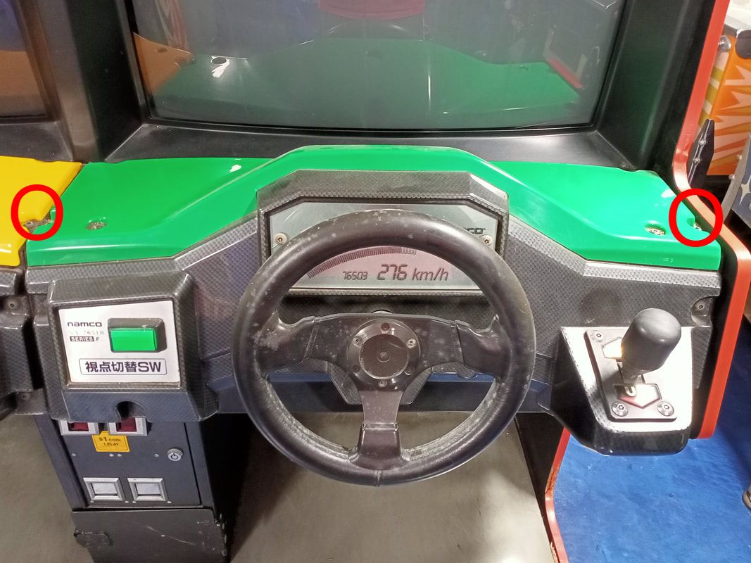
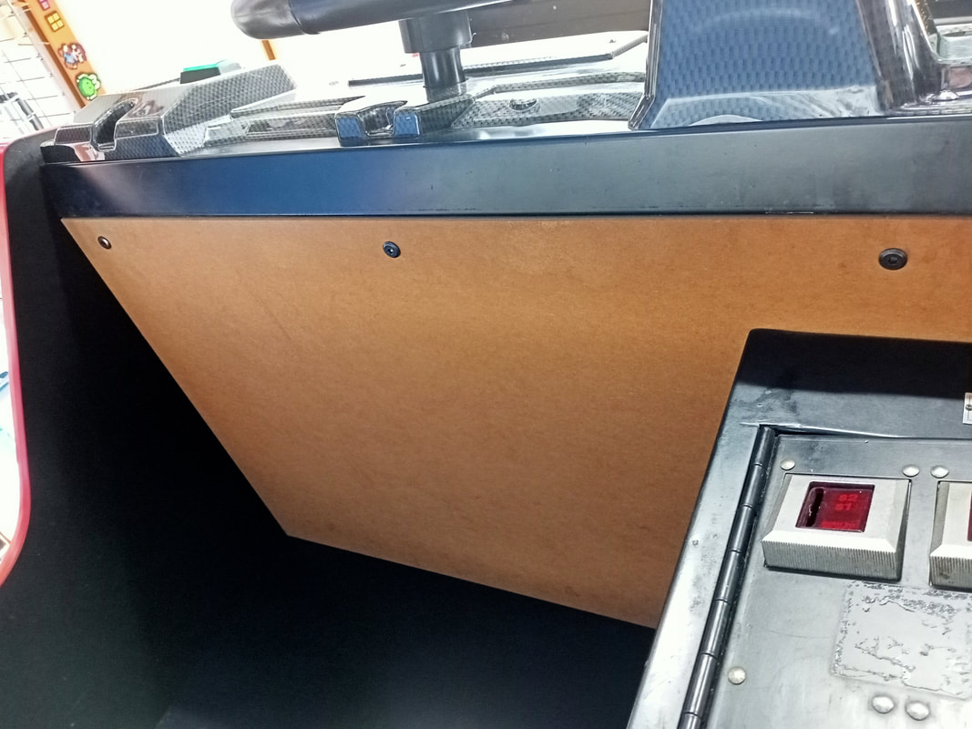
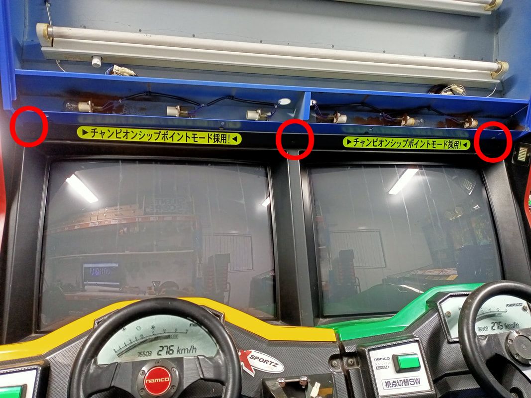
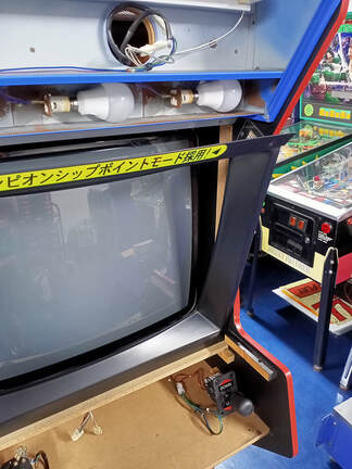
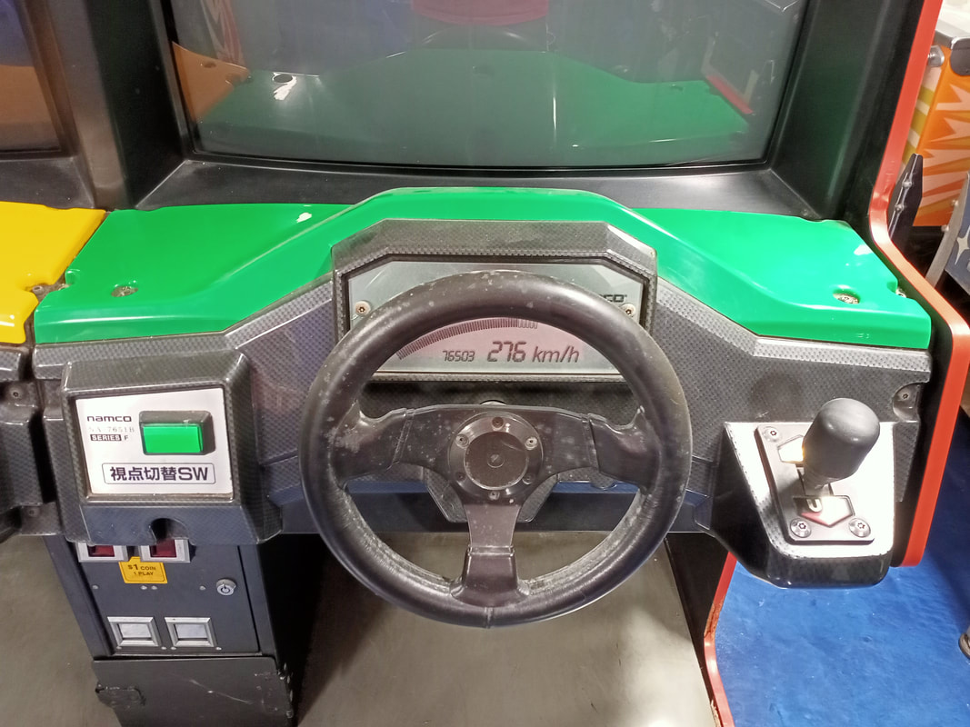
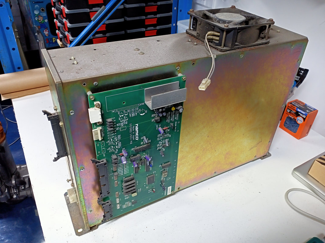
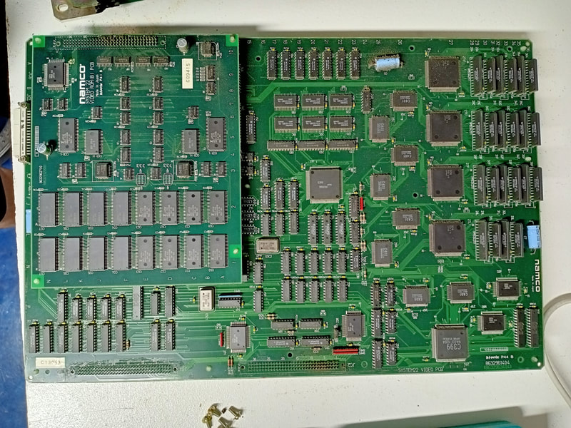
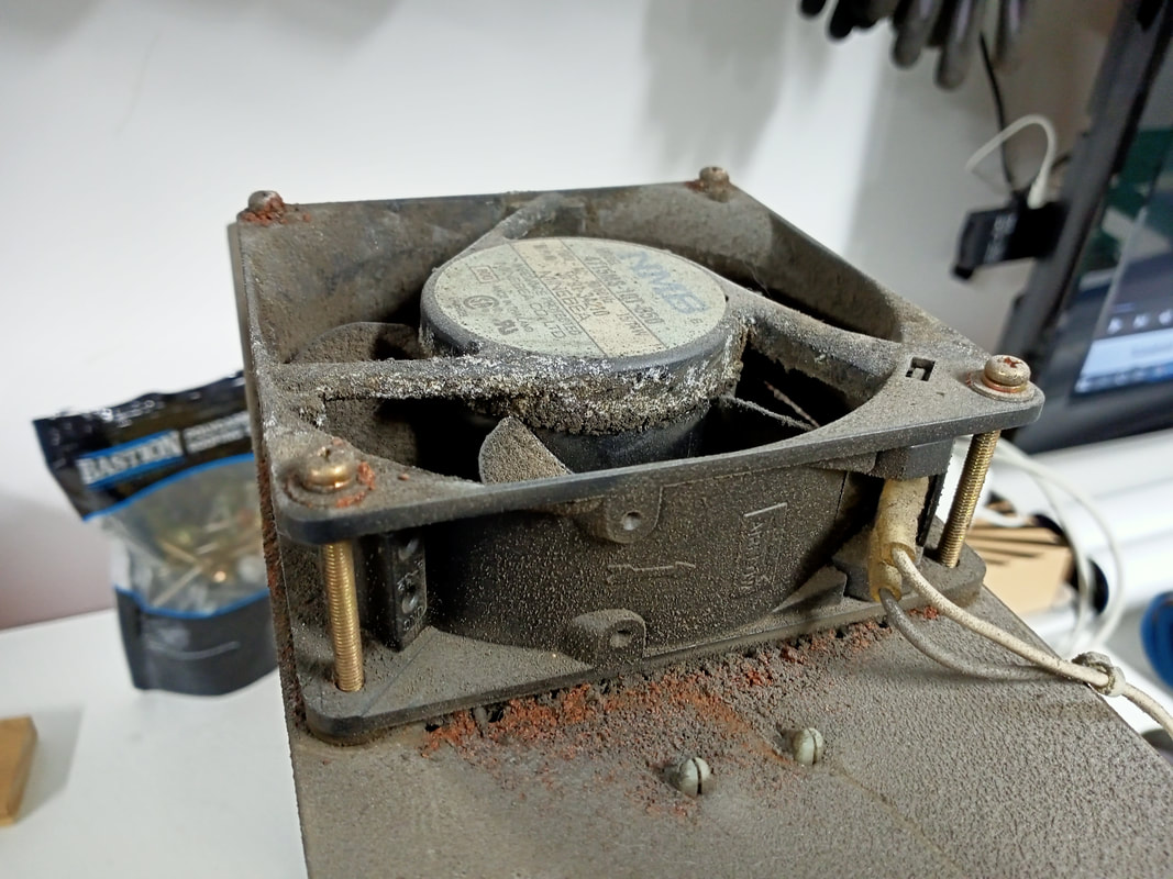
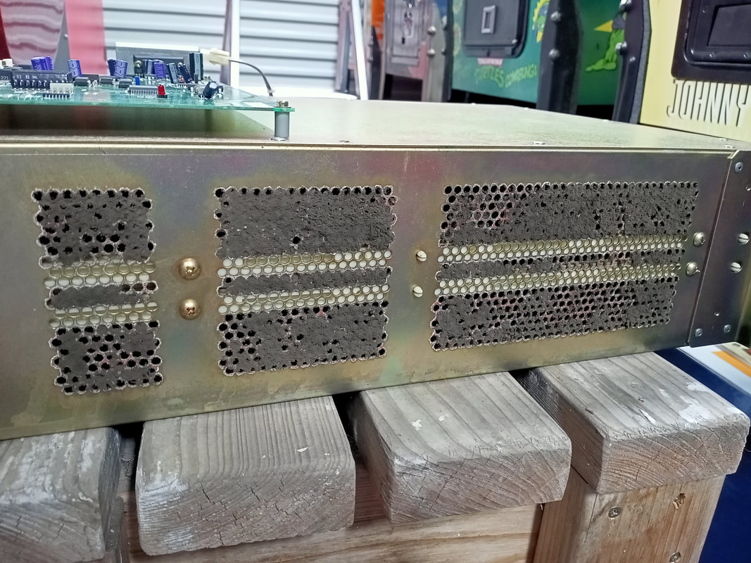
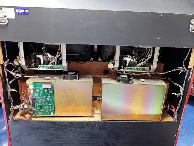
Victory Lap is a Namco System 22 game, which was a little different to the System Super 22 Cyber Cycles I had worked on previously. The System 22 board stack cages were much larger, but consisted of only two main PCBs, with a couple of daughter PCBs mounted to them. The board cages and fans were filthy, and needed a good clean. The cabinet interior was otherwise all original, and showed no signs of being hacked up or messed around with. The exterior of the cabinet, however, was a different issue. There was water damage to the rear right corner, where water seemed to have dripped down onto the cabinet. I suspect this was because this game was stored in an old, rusty shipping container for several years before I purchased it. This cabinet was in the far corner of the container, and the container was on a slight downhill slope. Any water falling on top of the container would have come down onto this cabinet, and I suspect this container was no longer watertight. Apart from the water damage, the cabinet was otherwise intact and all of the game's parts appeared to be present. When I got the game home, I did a little tidy-up of the wiring within the cabinet and checked that there was nothing obvious wrong with the monitor chasses. Everything seemed OK, so I took a chance and turned the game on to see what would happen. Initially I got nothing but a light on in the topper. After a couple of tries, however, I got a successful game boot. Although I found a number of other issues while running the game through its diagnostic tests, I was happy enough that it was booting up and playing that I made a start on the tear down and disassembly. Disassembly There is a game manual available online which describes a UK-built cabinet. The dimensions and cabinet parts are the same, but some part numbers and component specifications are slightly different. Nevertheless, it is a good reference for understanding all of the parts of the cabinet. Most of the larger parts are fairly straightforward to break down, such as the topper and the seats. The mounting screws for those are all visible and easy to access. However there is one part that the manual doesn't provide any instructions for removing, and isn't particularly obvious. That part is the monitor bezel. On Ace Driver cabinets, the two monitors have a single, moulded bezel. The bezel is tucked behind the steering assemblies and the topper, and you'll ideally need to remove both of these in order to get to the bezel. First step is to remove the steering wheel and dashboard assemblies. For each side, unscrew the gear shifter (four screws) and unplug it. Then remove the two screws on the left and right of each dashboard assembly (topside) and the three screws on the underside. Next, unplug all of the connectors for the steering assembly. There are three in total (four if you include the connector for the gearbox, but you should have already undone this one in the previous step). Next, undo the three screws securing the bezel to the bracket at the top of the monitors. For this next bit, it helps to remove, or at least loosen, the topper. The bezel can be removed without removing the topper, but it does make the job a lot easier as you don't have to bend the bezel at all to get it out. Loosen the three screws which secure the topper to the front face of the cabinet, as well as the screws at the top rear of the cabinet which secure the topper externally. At this point, the bezel can be removed. If you haven't removed the topper, you will want to lift it slightly with one hand while handling the bezel with the other. It helps to have a second person help with this! With the topper raised ever so slightly, the bezel can be pushed outwards from its top edge, "popping" it out from underneath the topper brackets on either side. Then simply pull it forward so it clears the cabinet, and lift it out. Done! With the bezel out, you have everything accessible for cleaning and servicing. Disassembly complete! Note that the monitor tubes on Victory Lap are designed to be removed from the front of the cabinet, with no sufficient opening at the rear that can accommodate the tube. So, if you want to remove those for any reason, now is the time to do it. Tips & Troubleshooting (click on sections below to view details) Gear shifter adjustment
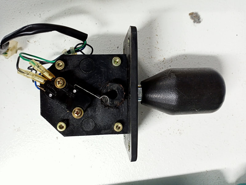
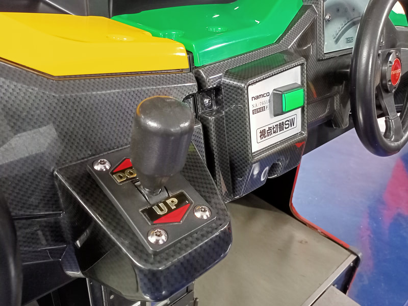
The gear shifter on the right side of the cabinet appeared to be in reasonable original condition. However, there was one problem. It wouldn't reliably shift up. Shifting down was OK, but there was a 50% chance it wouldn't work if you shifted up. Time to take it out to get a closer look. These up/down gear shifters are much simpler than the 4-speed shifters found in games like Daytona (Sega, 1994) and Sega Rally (1994). They only have two directions, and therefore only need two switches to work. I noticed there was a difference between the switch actuators for the up and down switches. One of them appeared to have been bent by hand, and had a different shape to the other, which was nicely rounded at the end. This misshapen one was the "up" switch having issues. All that was needed was to bend the actuator slightly so that it was more reliably triggered by the movement of the cam. That got the switch back into proper operation. Gear shifter replacement
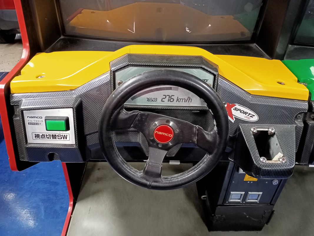
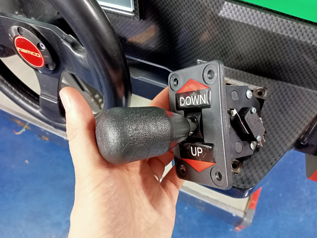
The section above dealt with adjusting the gear shifter for proper operation on the right side of the cabinet. But there was a much bigger problem on the left side of the cabinet - the gear shifter was missing completely. All that remained was the connector hanging from the hole in the space where the shifter once was. So at this point I needed to source a complete replacement. Part number X294-700 is printed in the manual, but doesn't produce any meaningful results.
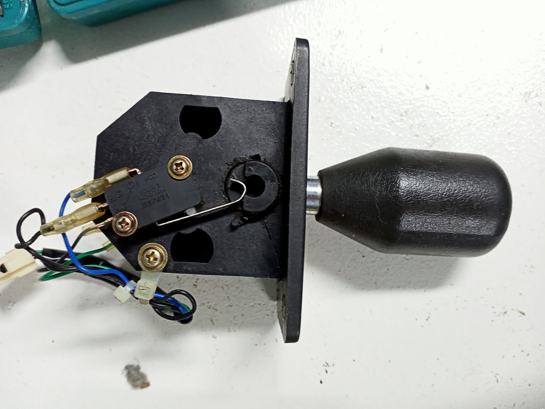
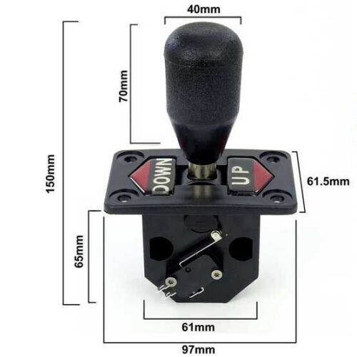
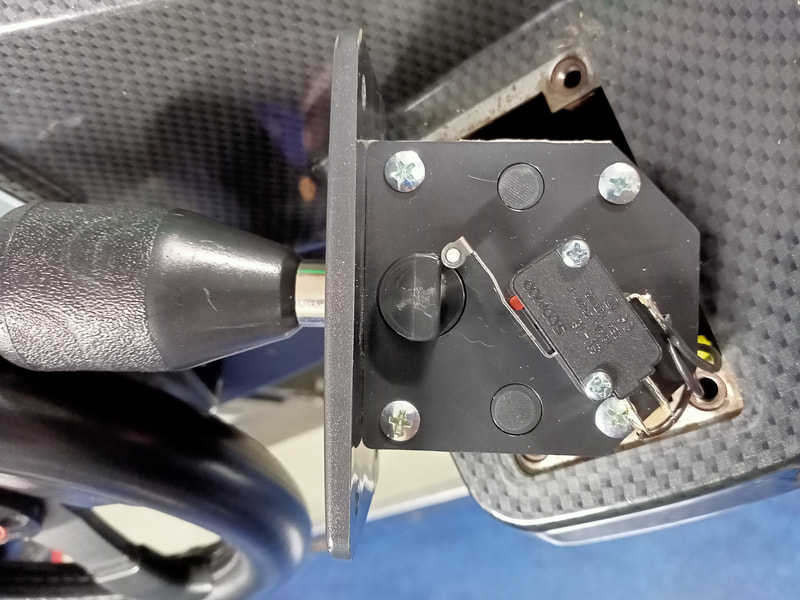
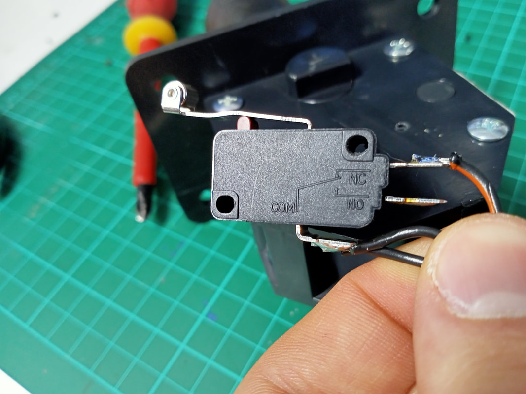
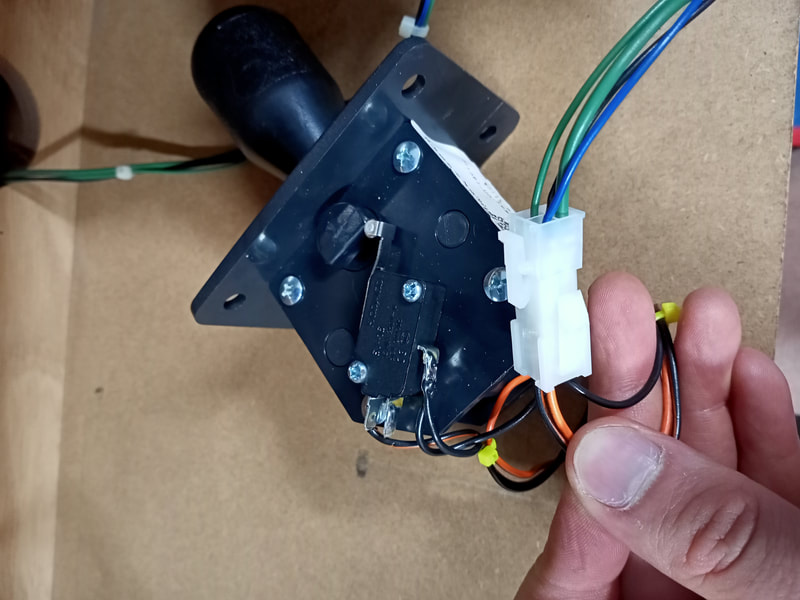
There appear to be two main styles of up/down shifter. One style is still available (Suzo Happ, Marco, PSPA) and is used on some driving games as well as The Getaway (Williams, 1992). However, this shifter is very large, and will not fit into the recess on the steering assembly. After some unsuccessful searching for NOS or used shifters, I decided to try and find what kind of brand new gear shifter assemblies were available to purchase. Surprisingly, I found that compatible shifters of the correct functionality and dimensions were actually readily available (AliExpress). The shifters on AliExpress come with microswitches which is a nice bonus. These shifters are fairly cheap so the quality is what you would expect; they feel plasticky and the shifting action is a bit stiffer than the originals. However, for an easily obtainable and compatible replacement, I can't complain. This shifter was not quite plug-and-play. I still needed to wire the microswitches into the game harness. One thing to note about these switches is that they have roller bearings on the actuators, rather than being rounded lengths of metal. The mounting holes are already drilled into the shifter, so all you need to do is attach the switch using the provided screws. However, once I did this, I realised that there was a problem. The length of the switch actuator arm and the rounded design of the cam on the shifter means that the roller on the switch actuator sits right on the corner of the cam. In this position, the switch remains always closed. The original switch setup is such that, when you shift gear, the cam pushes on the switch actuator to activate the switch. However, as the cam and switch setup in the new shifter was different, the new shifter wouldn't change actually change the state of the switch at all. However, if you pushed the shifter in the opposite direction, the switch would be allowed to open up. To get this new setup to work, I had to wire the switch in a different way to the original. Instead of having the switch open at rest and closed when shifting, I wired it to be closed at all times, and open when shifting. To achieve this I attached the switch wires to the normally closed "NC" switch terminals instead of the normally open "NO" ones which the original wires were attached to. Therefore, with the shifter in neutral, the switch would actuator would be pressed in, but the switch would still register as "open". When the shifter was pushed or pulled to go up or down a gear, this would allow the switch actuator to release, and register a switch closure. The last job was to install a new connector between the shifter and the wiring harness. I had to remove the old connector as I was unable to find the right male connector housing to mate with it. You can grab a 4-position connector housing and crimp pins locally (Jaycar) which works just fine. If you find that you get confused with the wiring and the game shifts down when it should actually shift up, simply swap the microswitches around on the shifter and you'll be back in order. Alternatively, you can swap the switch wire from one switch to the other. Same difference. Topper repairs
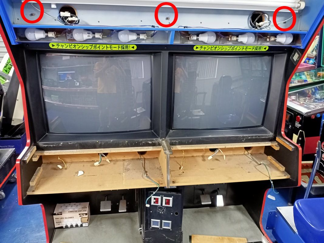
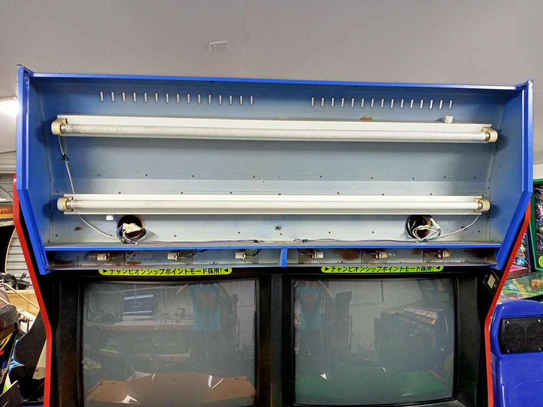
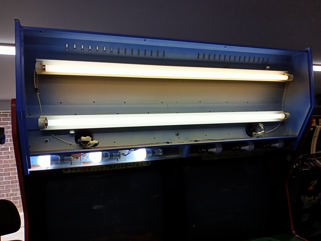
I had little luck with the topper when I first turned the machine on. I had a little light towards the bottom of the topper, and only the green race leader lamp was flashing. When I removed the topper plastic, this is what I found.
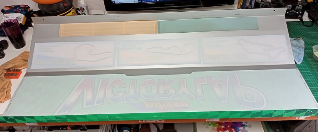
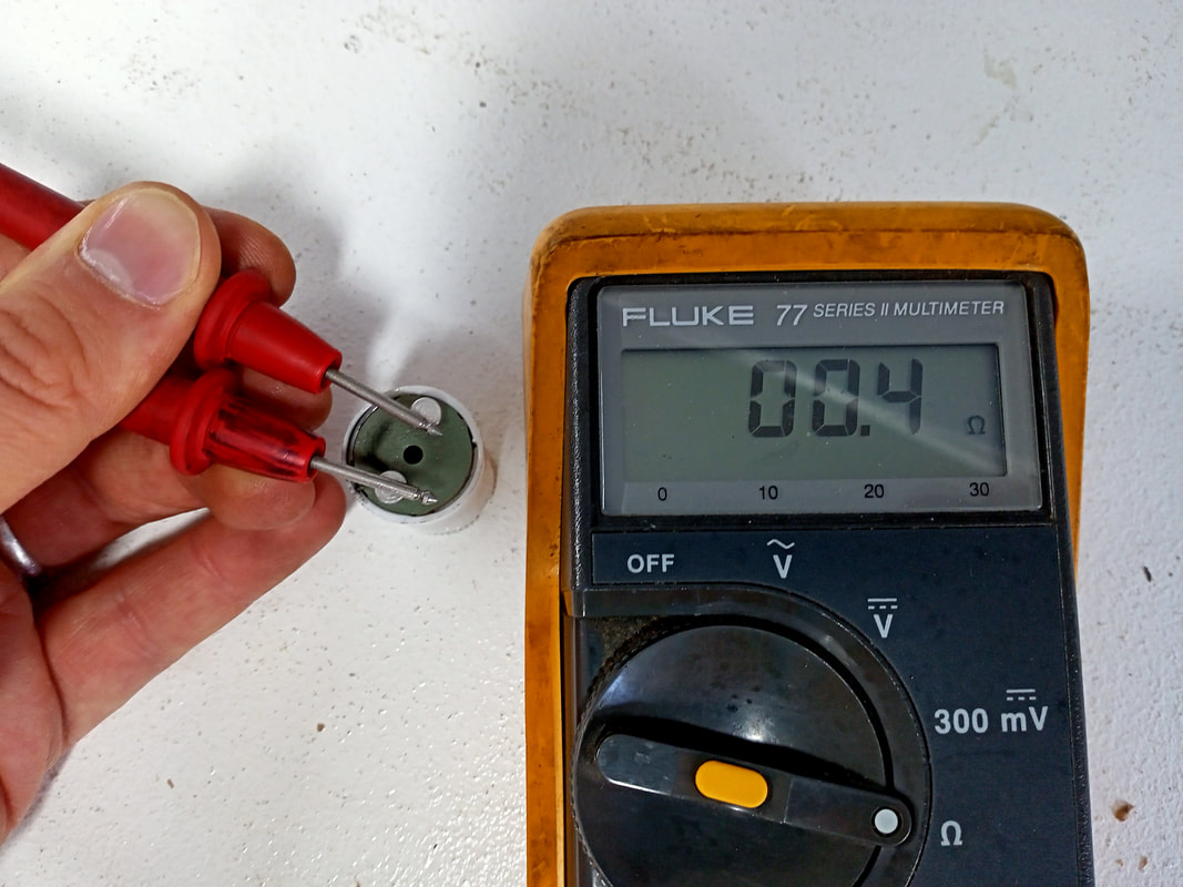
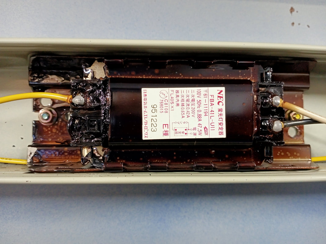
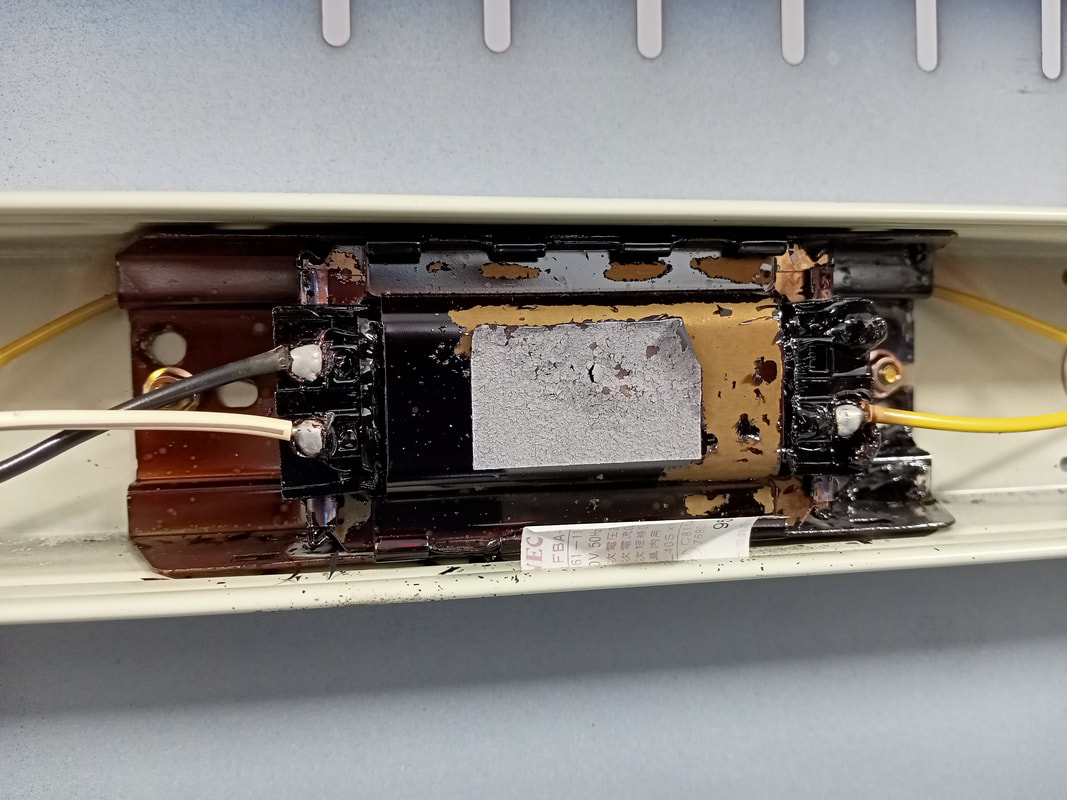
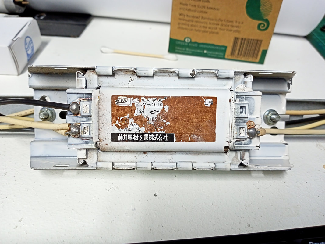
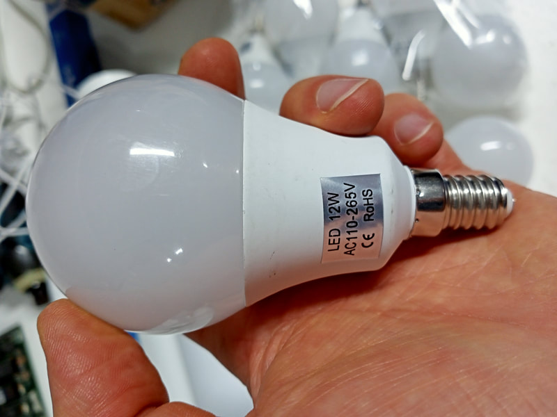
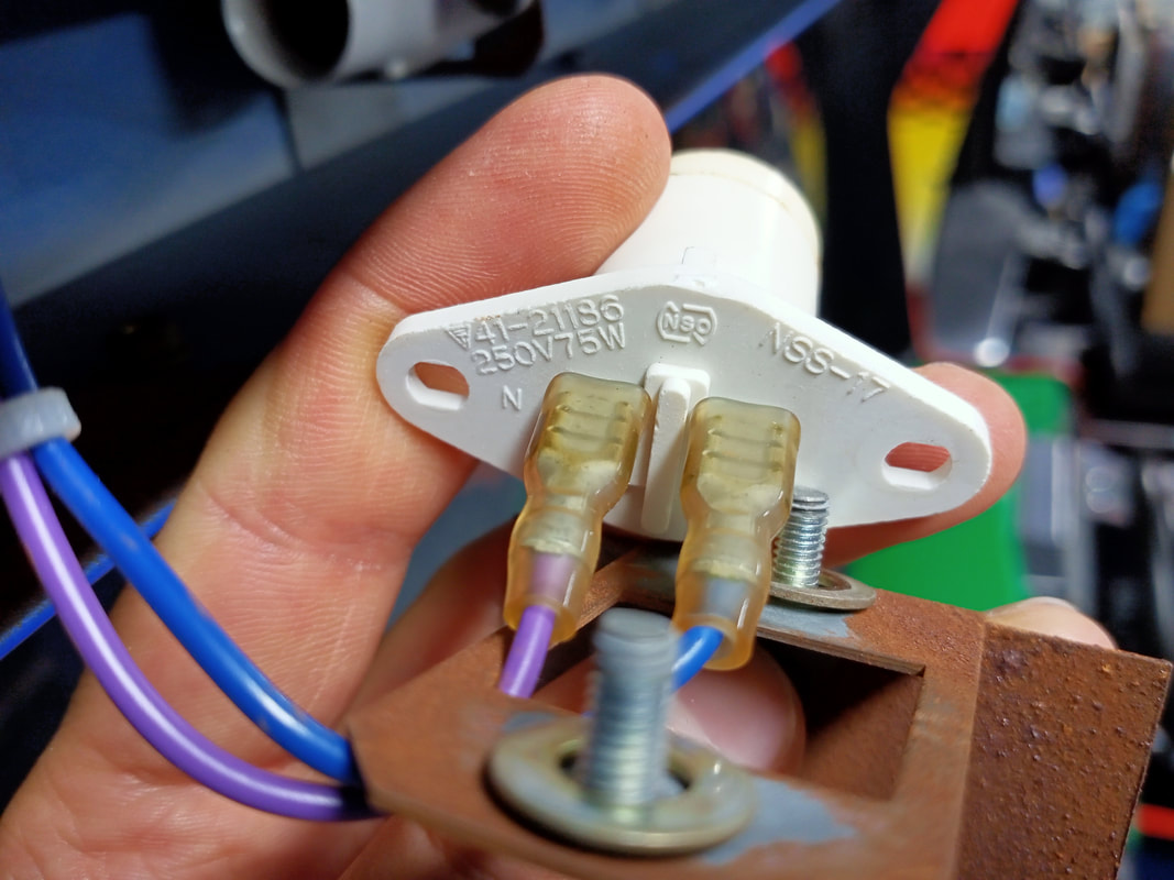
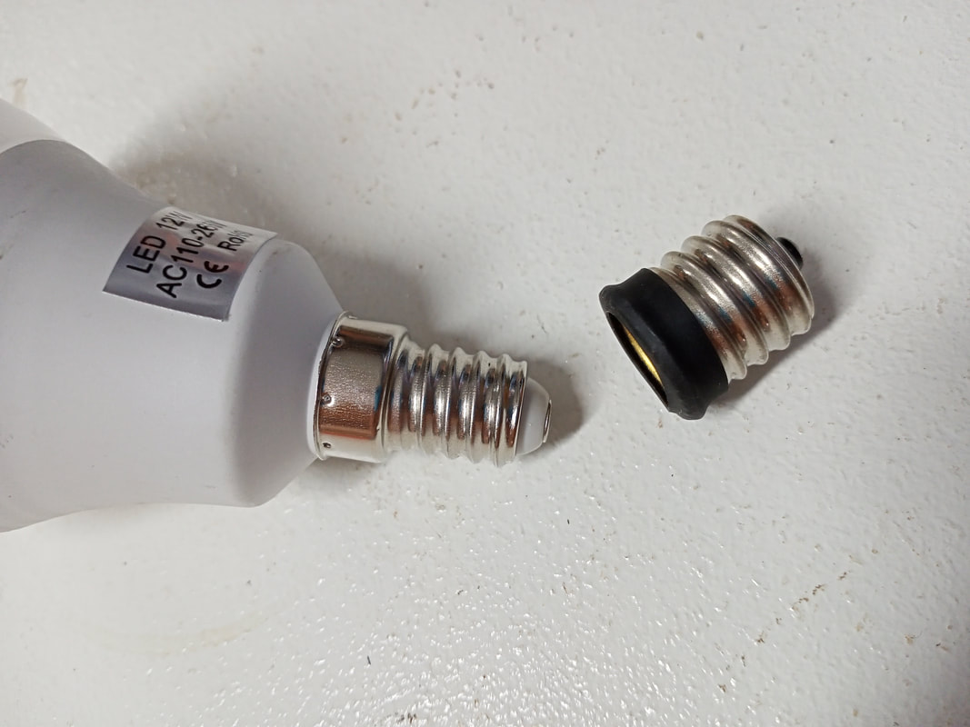
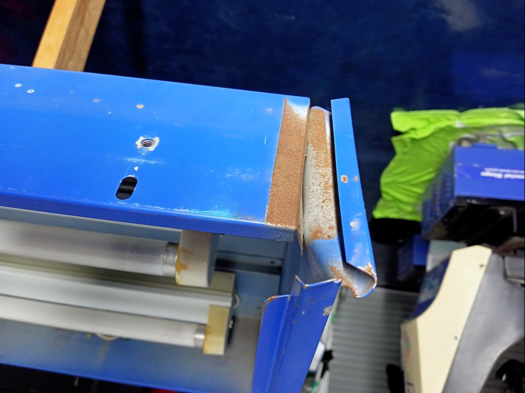
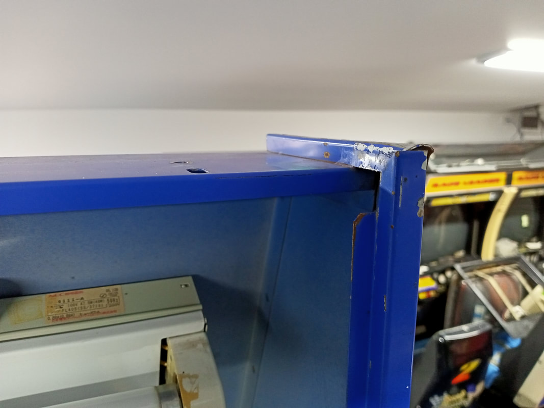
There are two fluorescent lamps which light up the top section of the topper, and the yellow and green race leader lamps are actually composed of three smaller light fittings above each of the monitors. A piece of yellow and green plastic over the clear plastic window is what gives the lamps their colour here. So, the lighting situation in the topper was pretty sad. I decided to tackle the non-working fluorescent lamp first. The fluorescent tube had a black section at one end, which was also a sign that the tube was probably dead. I tested it in the lower fixture and confirmed that it was, indeed, dead. I whacked a working tube into the top fitting to see if that made a difference. Still nothing. So, the problem was elsewhere. I looked at the starter and while it seemed OK visually, I tested it with my meter. Almost a dead short. The starter from the working fixture had a few ohms of resistance in it, so I assumed this meant that the starter was shot. Plus, I was replacing the fluorescent tube anyway, so I needed a new starter. Unfortunately, most of the readily available starters here are meant for 240-volt light fixtures. The problem on our machine is that every mains voltage load is fed 110-volts by the transformer. However, I had a quick solution in my pinball parts box. Stern (as well as some late Sega) pinball machines used fluorescent lamps to illuminate the backglass. These were also 110-volt fixtures, and a starter from one of these machines will work fine here, too (RTBB). I installed the new starter and turned the game on again. At this point I had a new fluorescent tube and a new starter. Still no light. At this point there is only one part left in a fluorescent lamp circuit to look at - the ballast. I opened up the fixture to see what was going on with the ballast, and as soon as I removed the cover, I realised what the problem was. The photos below are a comparison between the ballast in the working fixture and the non-working one. The ballast in the non-working fixture was shot. It looked like it had melted, and the black potting material had started to leak out of the casing. The label on the front of the ballast had disintegrated, and one of the wires fell apart and away from the ballast when I touched it. No further testing needed! We need a new ballast. The problem is that compatible ballasts are getting harder and harder to source, and 110-volt units are almost non-existent in Australia. Plus, they're heavy items, so postage costs are always a killer. I ended up cheating a little bit to replace this ballast, as I simply removed one from my Sega Rally Championship (Sega, 1994). Sega Rally has a single fluorescent tube in the topper, and I plan to replace this one with an LED fixture, so using the ballast in Victory Lap seemed like a good way to save it from landfill. Once the new ballast was in, along with the new starter and the new fluorescent tube, the tube lit up like it should. Success! Next lighting issue: the race leader lamps. There were six lamp fittings in total, and only two of them had bulbs installed. Only one of these was working, and the other had a broken filament. These lamps were typical glass bulbs (120 volts, 40 watts) with no special shape or reflectors, so I just needed to find appropriately-sized replacements. I decided to get LED lamps, because there really isn't a reason to use incandescent bulbs anymore. However, these were not typical Edison screw bulbs. These were much smaller. I made my first mistake here when I looked in a copy of the game manual I found online. Now, this copy was published in England by Namco Europe. Page 30 references the topper lamps, and refers to these ones as E14 style golfball bulbs. E14 lamps are fairly readily available online, so I bought some (AliExpress). When they arrived, I found out that they did not fit. They were very loose in the socket. What the hell? Taking some measurements, I realised that the lamp socket was not actually an E14 socket as described in the manual. It was actually an E17 socket, which is slightly larger. Seems like the Japanese version of the cabinet stays true to Japanese lighting standards. That serves me right for looking at the manual instead of just checking the "NSS-17" number on the rear of the socket. So, I had a bunch of E14 lamps that didn't fit. I didn't want to throw them out, so I decided to buy some E14 to E17 adapters (AliExpress). This was cheaper than buying a new set of E17 lamps, which are surprisingly much more difficult to purchase at the correct voltage rating and in an appropriate bulb style. These are small adapters that screw into the socket, and are the correct size for an E14 lamp base to be inserted into them. With the adapters installed and the fluorescent light fixtures all fixed, the topper was now fully lit. Finally, there was some minor damage to the metal frame of the topper. The top right corner of the unit had been bent outwards, so that the plastic for the marquee no longer had any support on the right side. This just took some time with pliers and a mallet to ply the metal back into the correct shape. Steering assembly cleaning and force feedback issues
I had issues getting the force feedback system to work on the left (yellow) side. The force feedback motor tests in the test menu did nothing, and I felt no feedback on the steering wheel in-game. The right (green) side force feedback worked fine. Time to troubleshoot.
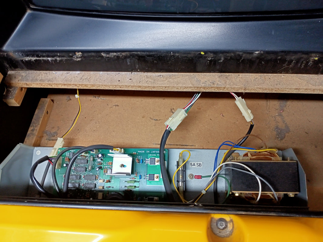
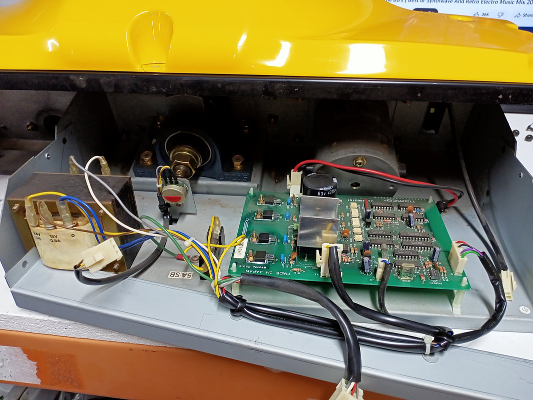
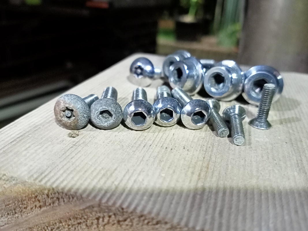
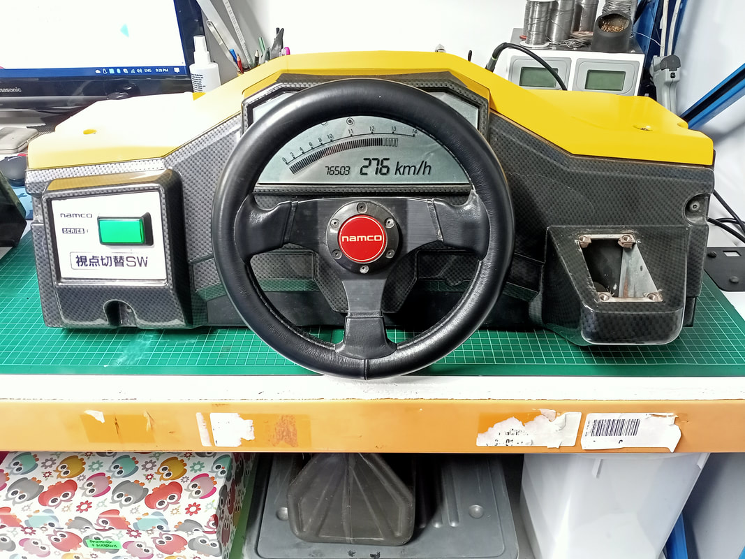
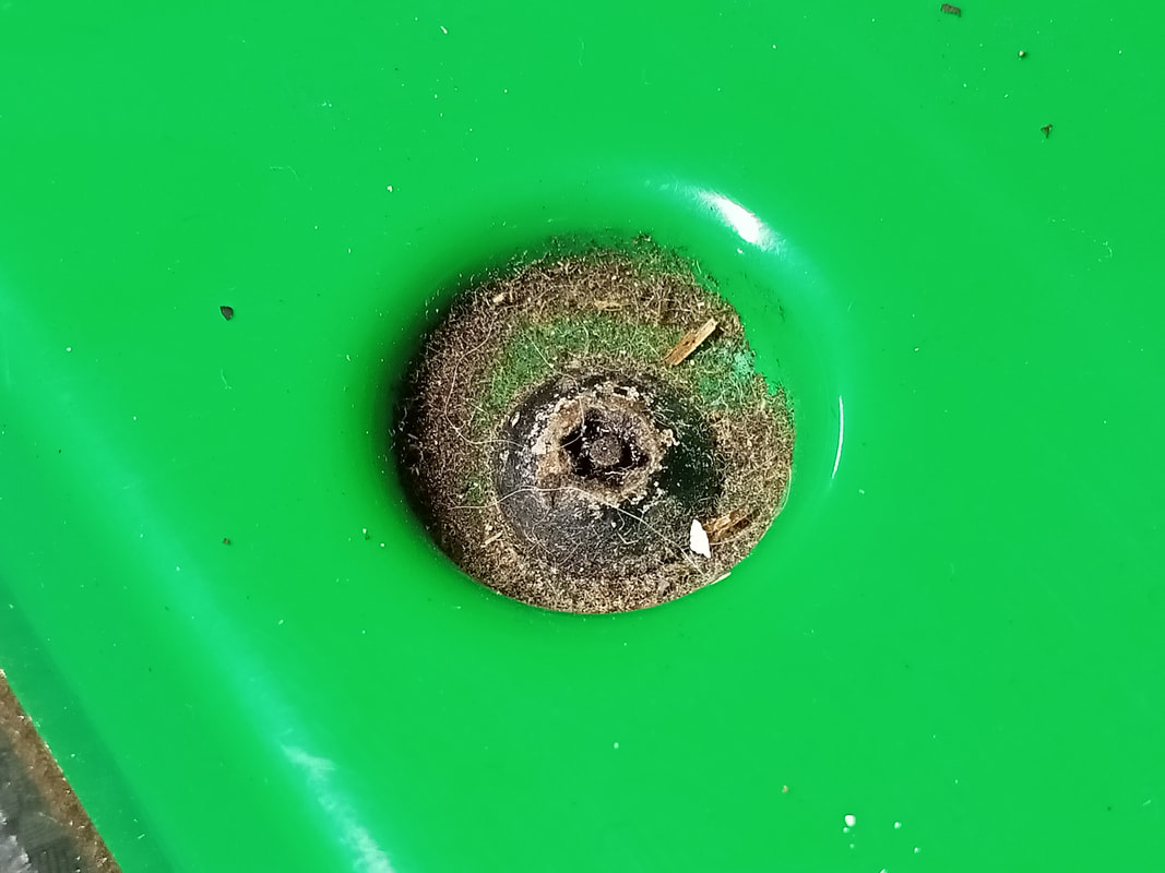
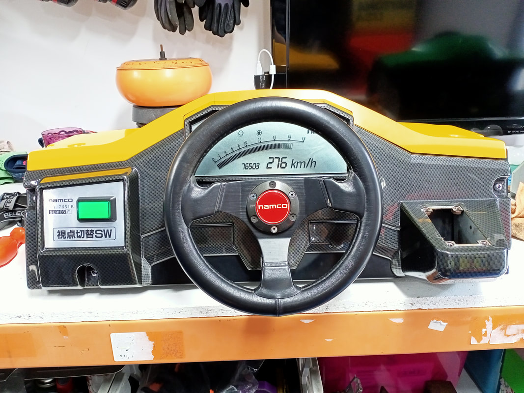
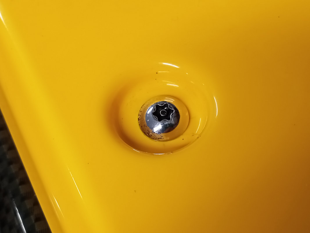
First, let's look at the rear of the steering assembly. There's a little bit involved in getting the assembly out of the cabinet, but it is much easier to remove the whole thing and inspect it on the bench. Check the disassembly section above for details on how to remove it. The assembly consists of a transformer which supplies power to the drive force feedback circuit board. A 5 amp fuse between the transformer and the circuit board protects the 24-volt winding on the transformer. Behind the transformer is the steering potentiometer, connected to the steering shaft. The large motor to the right is the force feedback motor. The force feedback motor and the steering column are connected via drive belts behind the dashboard cover. I didn't see anything amiss in this part of the assembly. There are two fuses that should be checked here: the 5 amp fuse mentioned above, and a fuse soldered to the force feedback circuit board, marked F1. Both of these fuses had continuity through them. The drive belt connecting the force feedback motor to the steering column was also intact. I gave the assembly a clean and decided to test it on the other side of the cabinet. I got a little carried away and decided to polish all of the screws on the assembly, too. These get filthy because dirt and debris accumulates in the depressions that the screws slot into. They looked much nicer after a clean and polish! I pulled the right (green) side steering assembly out of the cabinet, and replaced it with the yellow one. Then, I installed the green assembly onto the left side. I booted the game up, and went into test mode. Force feedback worked perfectly on the yellow, but not the green assembly. This proved that there was no issue with any of the mechanisms in the assembly. The issue was elsewhere. I decided to swap the game board stacks around to potentially narrow the issue down to a board fault. This didn't appear to make a difference. So, I swapped the board stacks back, and also swapped the steering assemblies back to their original positions (yellow on left, green on right). I went into test mode one final time to think about what to check next, and to my surprise, the force feedback worked on both sides of the cabinet! I suspect a connector on the left side board stack was not making proper contact until I reinstalled it. There were no issues with the connector pins or wiring to suggest they needed any repair. There were no other issues with the force feedback after this point. So while this one was a bit of a mystery issue, it only seemed to be a temporary one. Cabinet woodwork repairs
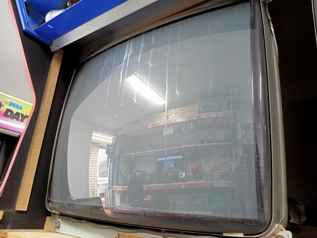
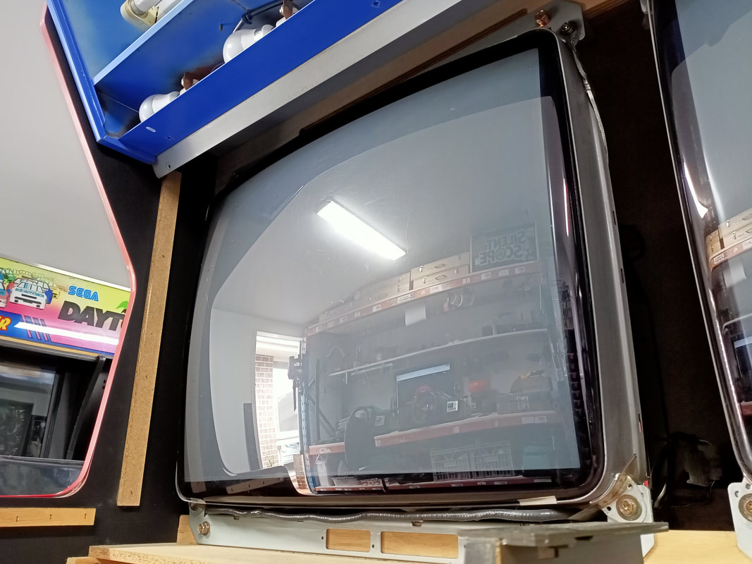
The timber cabinet itself was in fairly poor shape. The game had been stored against the rear wall of a shipping container for several years and, unfortunately, had suffered some water damage during this period. Initially I observed some drip marks on each of the monitors, which worried me a little because I had to consider whether the monitor tubes had been destroyed by water. Thankfully, they had not, so I'm not sure what the drip marks on the monitors really were.
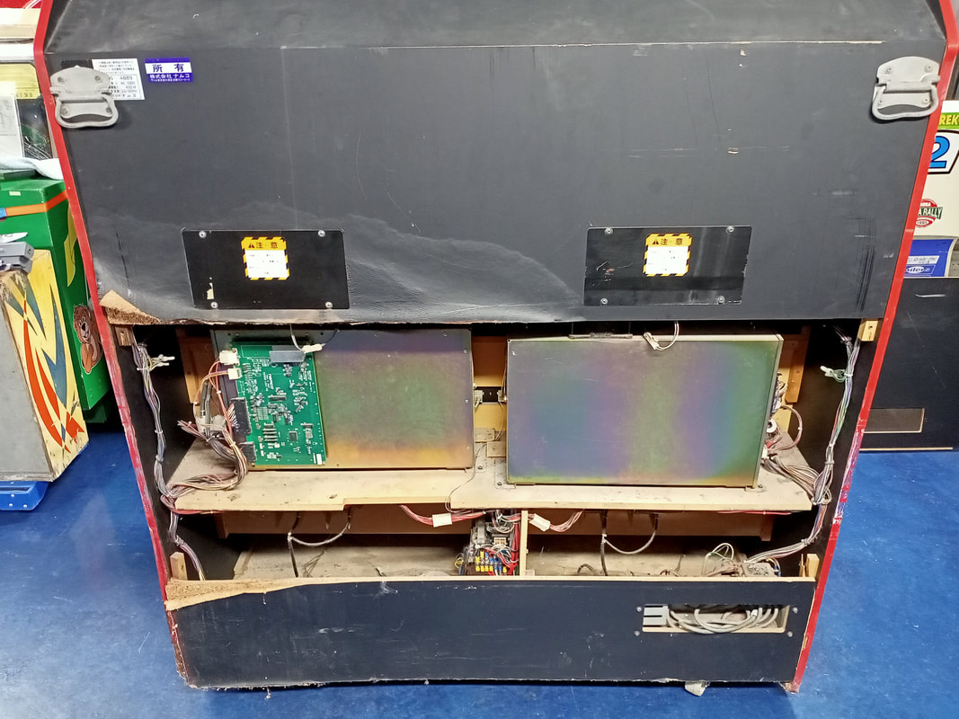
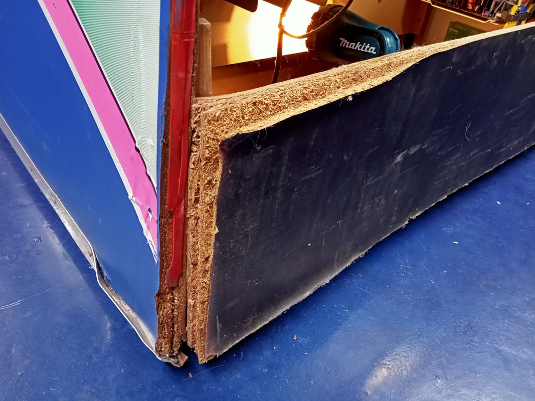
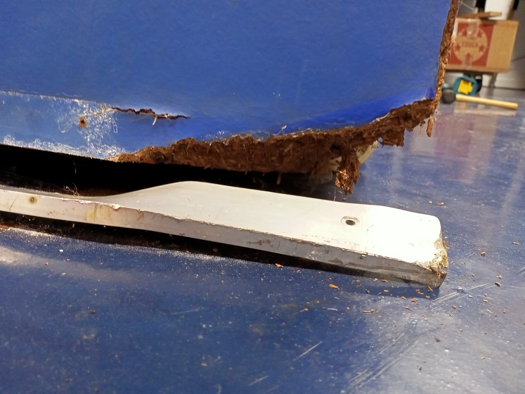
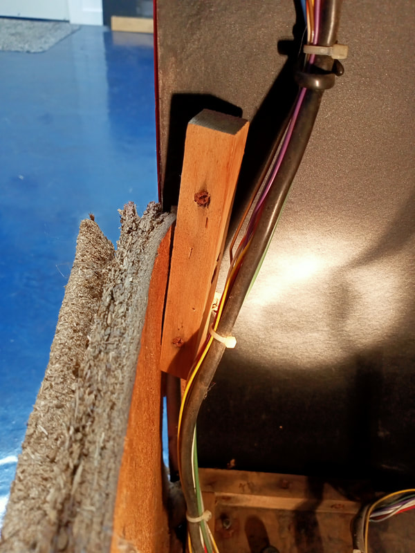
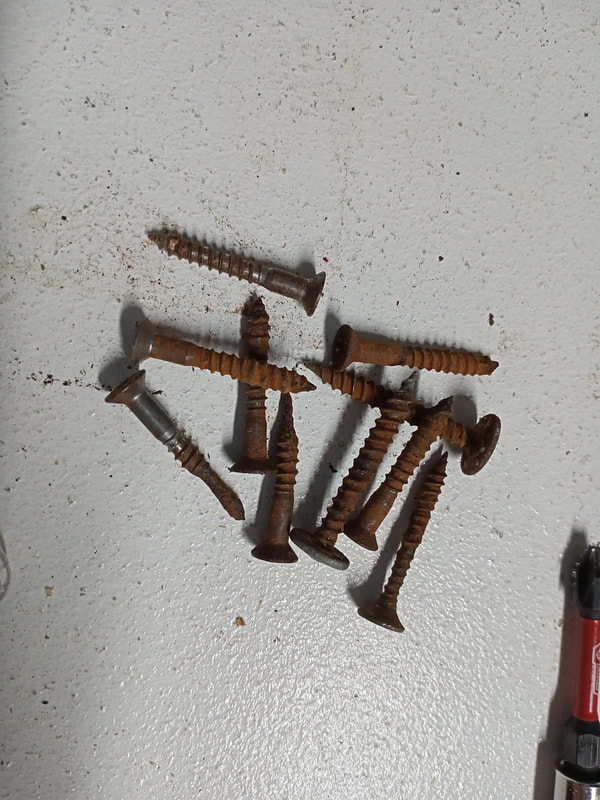
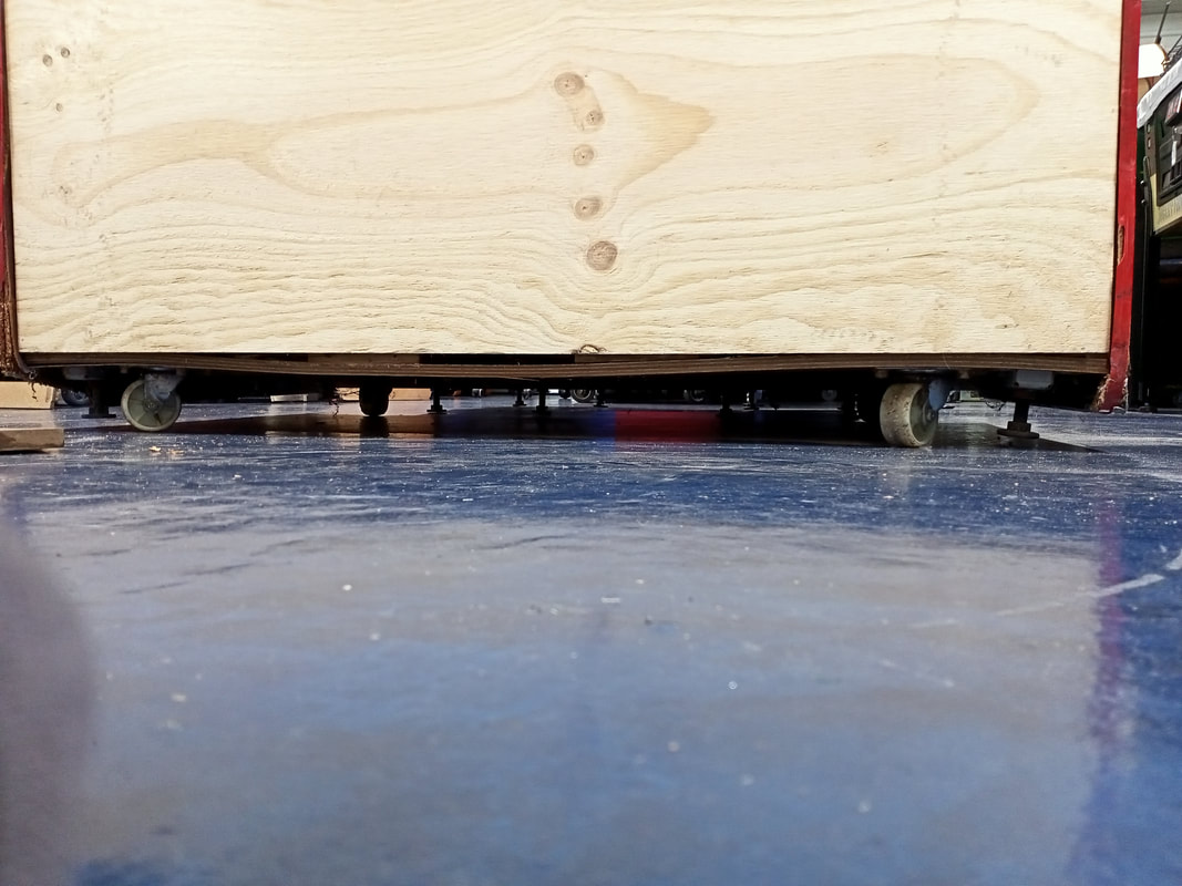
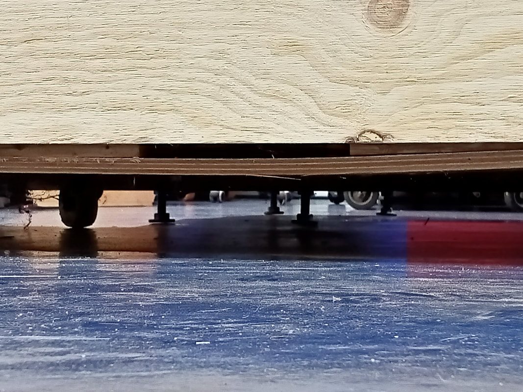
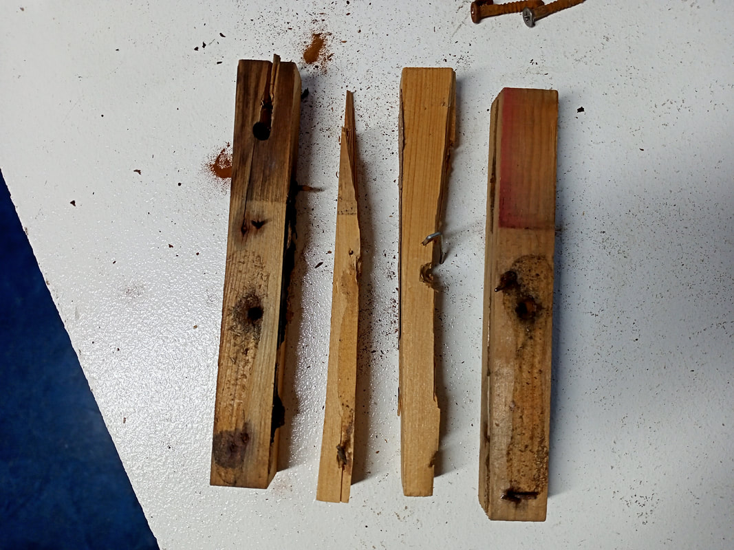
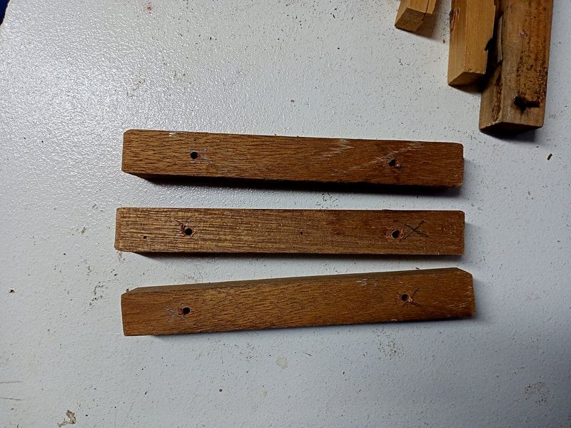
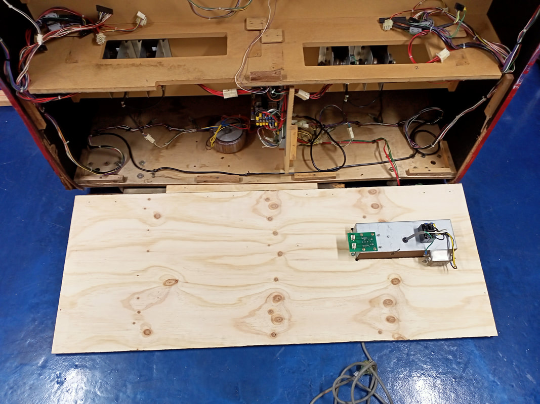
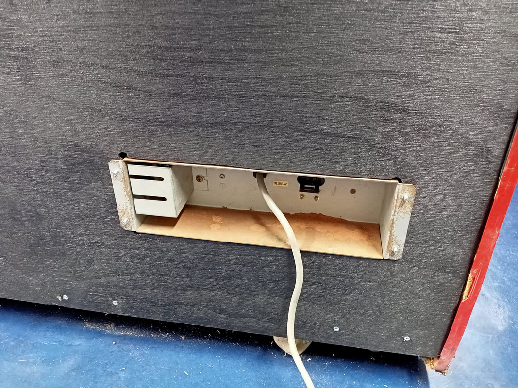
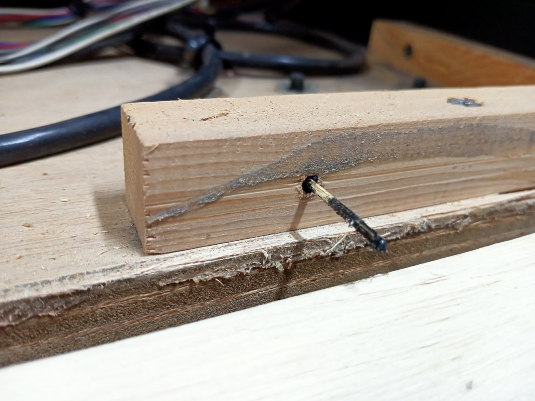
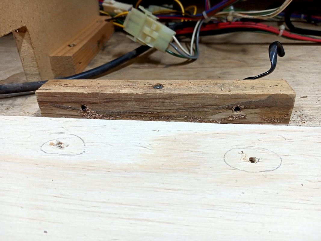
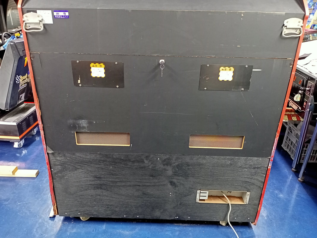
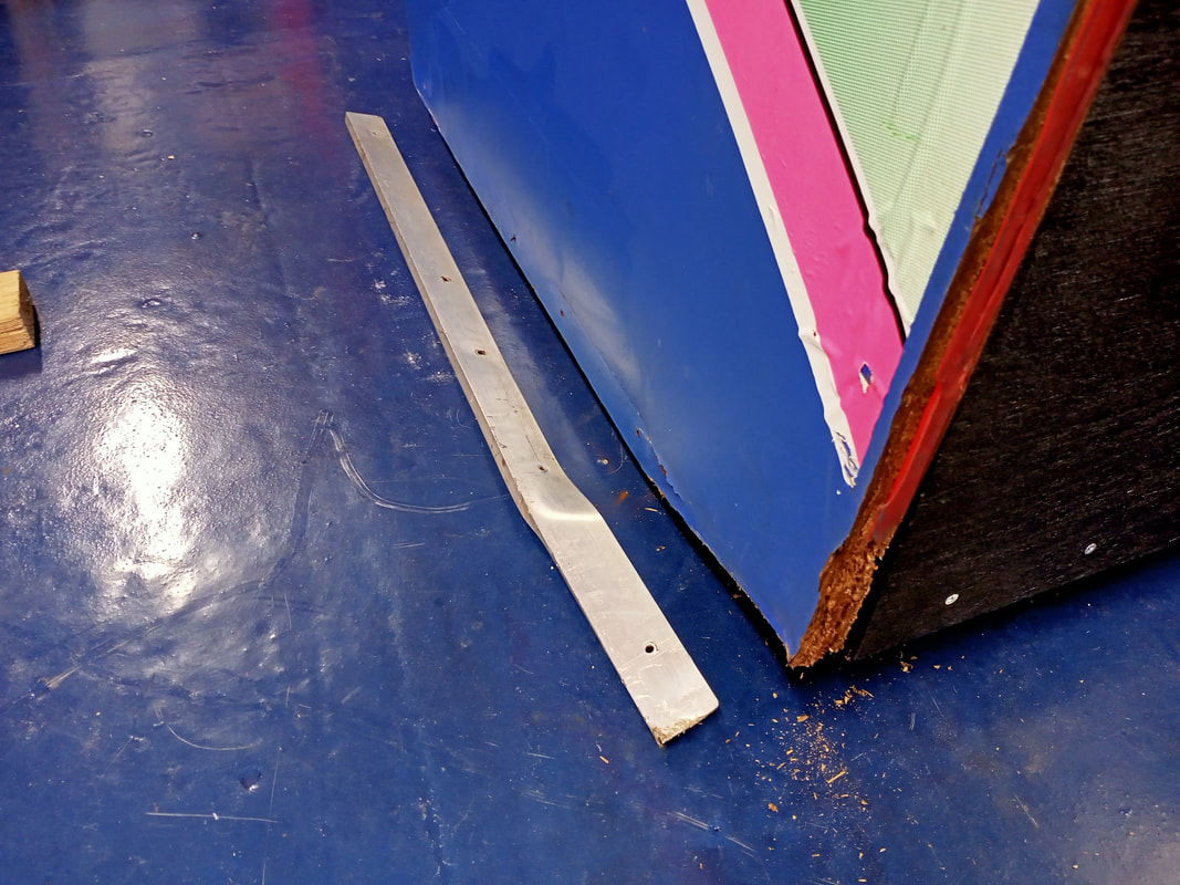
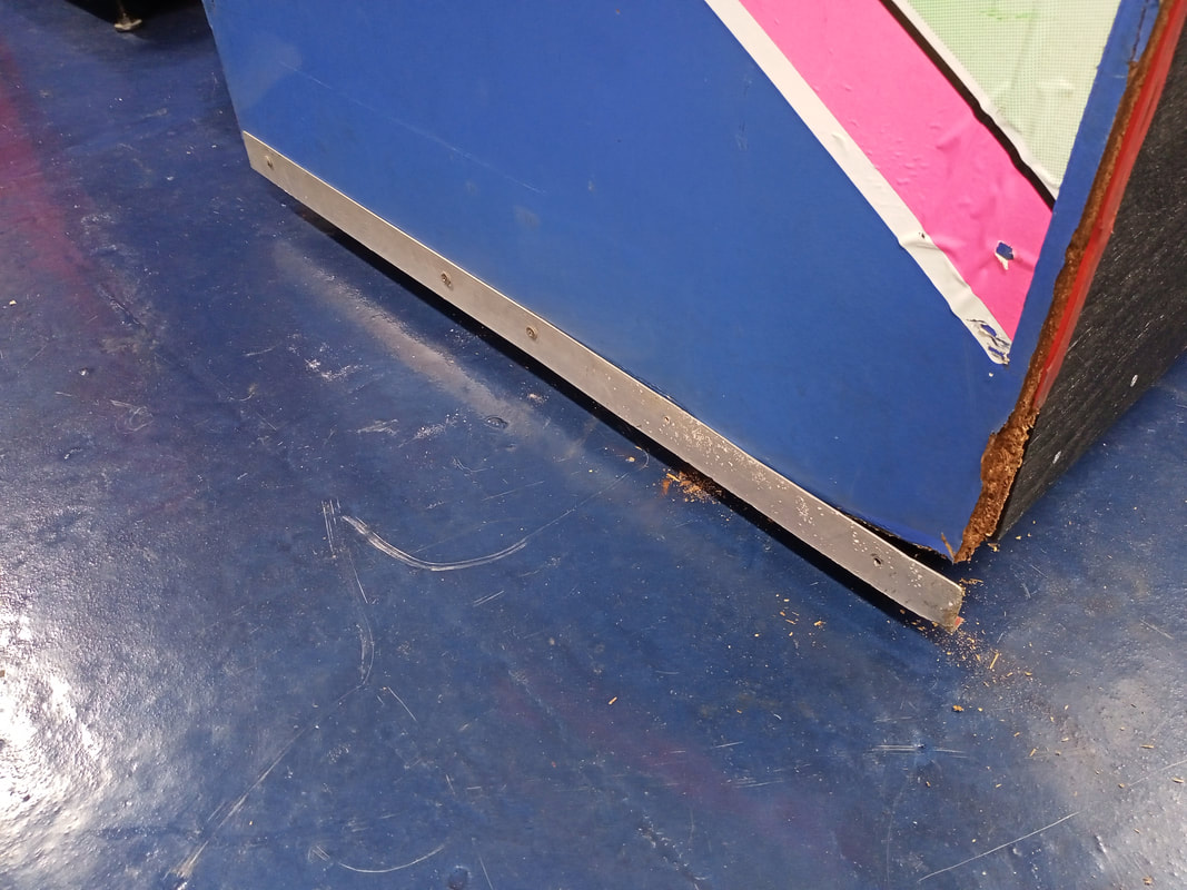
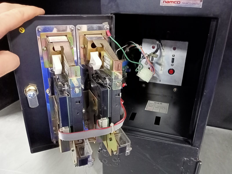
The real problem was at the rear of the cabinet. Water appears to have come into contact with the cabinet approximately halfway up on the left side. Here, it soaked into the chipboard rear panels which make up the rear side of the cabinet. It progressed downwards from here, and seems to have pooled a little on the MDF shelf which the board stacks sit on (luckily this did not cause any swelling, just some discolouration), with the majority of the water pooling on the floor of the cabinet. The floor of the cabinet is plywood, and it had warped where the water was present. It also soaked into the side panel of the cabinet (chipboard). This resulted in the metal bracket, which lines the bottom of the cabinet side, warping and pulling off the MDF which was originally in this corner. The result of all this water ingress was that the rear door panel no longer fit, so the cabinet could not be closed up. The structural damage to the chipboard panels at the side and rear was a cosmetic eyesore, but didn't detract too much from the structure of the cabinet itself; it was still stable and strong. Thankfully, water never went anywhere near the transformer, which is also on the floor of the cabinet. That was the good news. The bad news was that I would have to do some significant repairs so that the rear door panel could be installed and the cabinet could be closed and secured. Chipboard is a crappy material as it gets completely destroyed whenever the tiniest bit of water comes into contact with it. But, it's cheap, so it's in almost every arcade cabinet ever made. Unfortunately it's simply not worth rebuilding this entire cabinet from scratch, so I decided to remove whatever damaged sections I could, and create some new panels which I could install on the cabinet to replace the damaged ones. First step was removal of the damaged chipboard. The bottom section of the rear of the cabinet consists of a static MDF panel which has the power module attached to it, containing the line cord, line filter, and a cabinet linking circuit board. This panel is attached to the rest of the cabinet via corner blocks attached with screws and staples. Unscrewing some of these was difficult as the screws and staples were so rusty (and in some cases, bent). Nothing a bit of elbow grease can't fix, though! I decided to replace this lower panel with a fresh piece of plywood. I grabbed some measurements and bought a large piece of ply (Bunnings). Bunnings offer a cut-to-size service which is very handy when you need to cut long, straight edges such as this. When I got home I slid the timber into place. A perfect fit! However, it revealed another small problem. The base of the cabinet had warped from the water exposure, and was no longer straight. So I had to install the timber panel a little lower to ensure there were no gaps revealing the cabinet interior. I decided to make this panel about twice as tall than the original, as I could then re-use the door panel and simply have it mount a little higher. Once I had settled on the correct position for the panel, I needed to replace some of the corner blocks which had been destroyed by water damage, or were damaged during the removal of the panel. These are simply small, rectangular blocks of wood which fasten perpendicular panels together. I had some similarly sized wood in stock, so I cut it to size, pre-drilled some holes, and used some new screws to fasten them to the sides and base of the cabinet, ready to receive the new piece of ply. Getting there. Now it was time to reattach the hardware, namely the power module assembly. This assembly is a metal box that houses the power switch, link circuit board, and the line filter. The mains supply cable also enters the cabinet through this box. Originally, the box was mounted to the interior of the cabinet, and screwed in from the outside. I thought it looked a lot cleaner with the box attached to the outside of the cabinet, and screwed in from the interior, so I reinstalled it this way. I wanted to try and align the new lower panel with the screw holes in the corner blocks, but was finding it hard to figure out where to pre-drill the holes in the panel. With the panel held in the correct position, I dipped a bit of paint onto a toothpick, and stuck it through the existing screw holes in the corner blocks until it touched the panel, leaving a mark in the exact spot I needed to screw through the new panel.
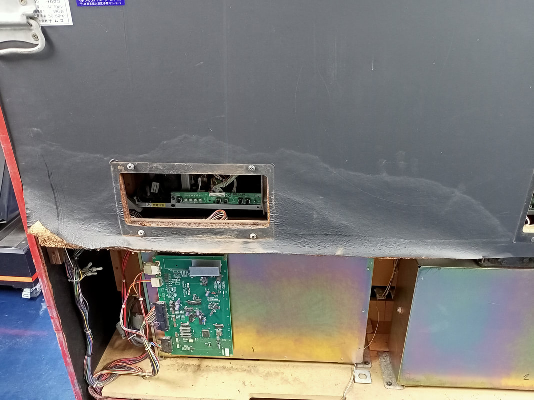
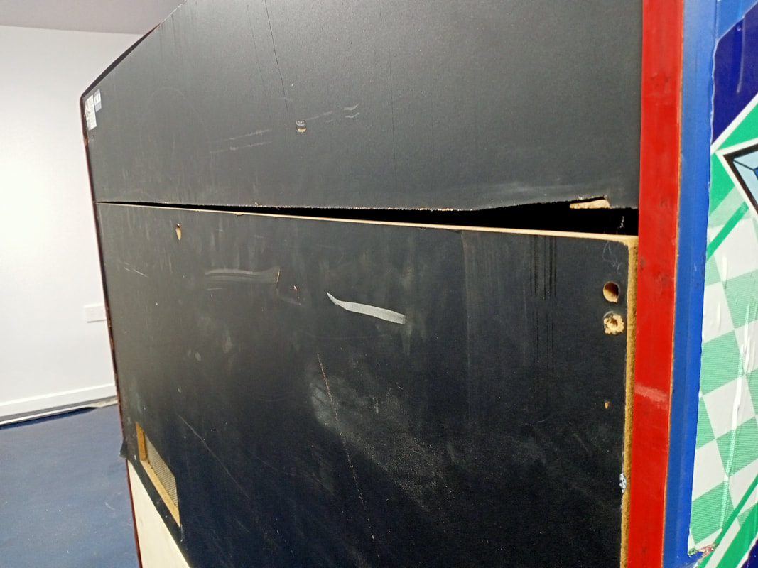
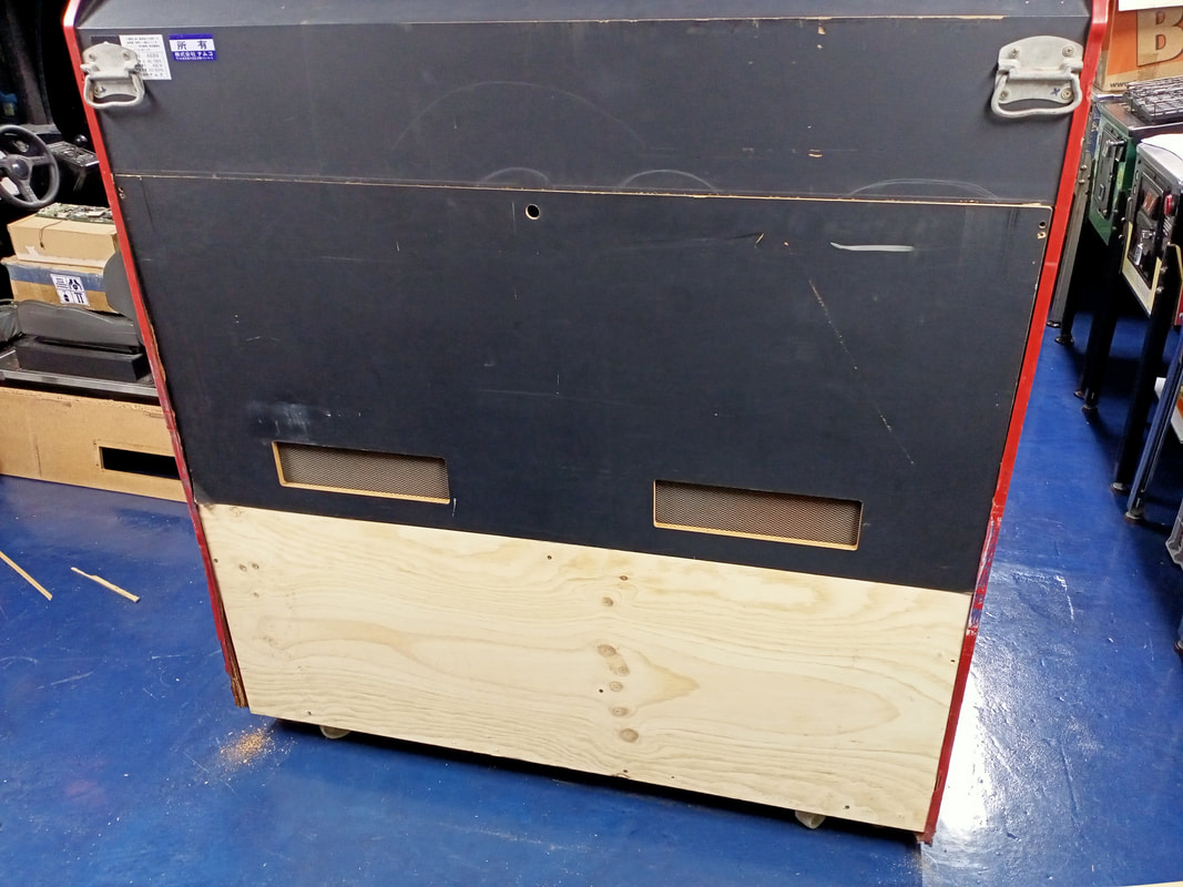
Now it was time to fix the upper rear panel, situated behind the monitors. I didn't want to remove this entire panel, as this would have been a much bigger job and the top half of this panel was intact. Instead, I decided to simply cut away the bottom half of this panel. This required a fair bit of cutting with a circular saw and jigsaw. It was a huge mess. I placed towels inside the cabinet to catch as much sawdust and debris as possible, but I still had to spend a lot of time cleaning up. Unfortunately I had to make several attempts at this because making horizontal cuts on a vertical cabinet surface isn't easy, as the below picture shows... Eventually, I got it to a point where there was a nice, tight gap between the top section and the removable door panel, and the cut was nice and straight. At that point all that was needed was a coat of black paint for the new bottom panel. I fitted a new lock to the removable door panel as well. In my opinion, even though it doesn't quite look original, it looks much better than what I started with. I debated whether to cut more chipboard away from the side panel of the cabinet, as this was water-damaged as well. However, this would be a very difficult panel to repair as it needed to be blue in colour, and I would have to reproduce the decal that covers the side of the cabinet. These decals aren't available anywhere, so it would be a lot of work to scan, touch up, and print it. I decided to leave it be. However, I did decide to straighten out the metal bracket which lines the bottom edge of the cabinet. This had bent out of shape due to the pressure exerted by the expanding chipboard. Some time in the vice and some flattening with a hammer got it nice and straight again. While it does look a little funky as it no longer connects with the rear corner of the cabinet, it looks much better than the mangled mess it was before. And that just about concludes the cabinet repairs. These repairs were fairly extensive and took a long time to carry out. Any repairs involving woodwork tend to be fiddly, especially when cutting timber to size. A cabinet this old is never quite square anymore, especially when structurally damaged by water, so any cuts you do make may need adjustments to fit nicely in a non-square void. But, such is life when working on 30 year old arcade cabinets. Seat repairs and cleaning
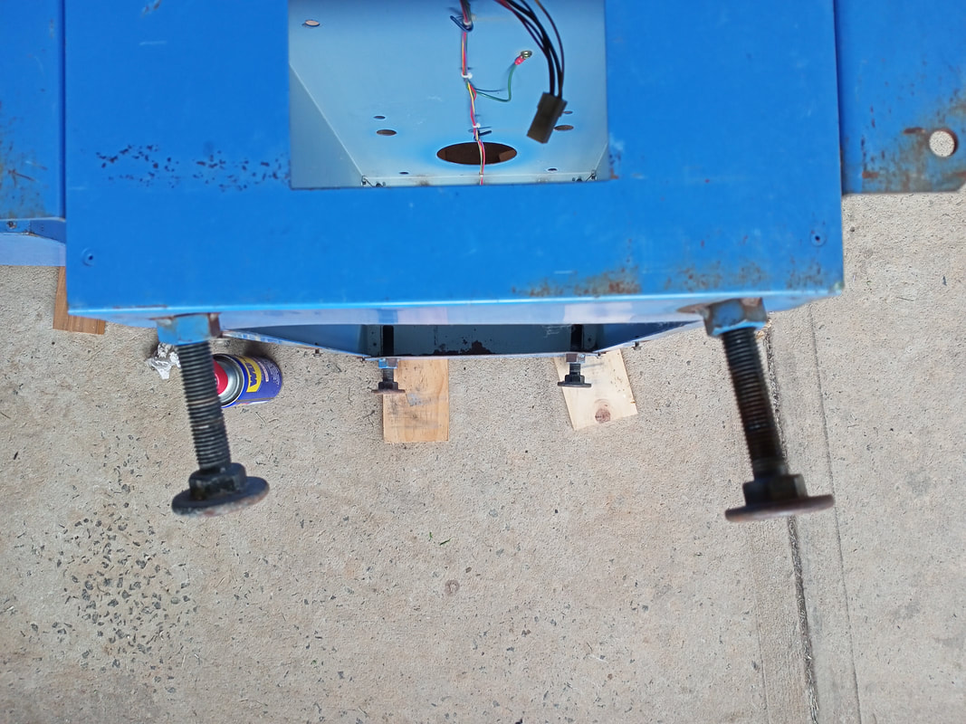
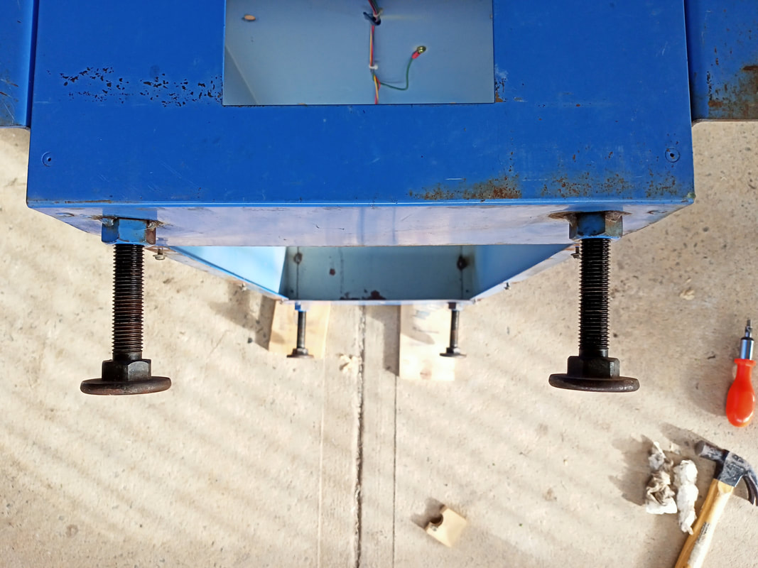
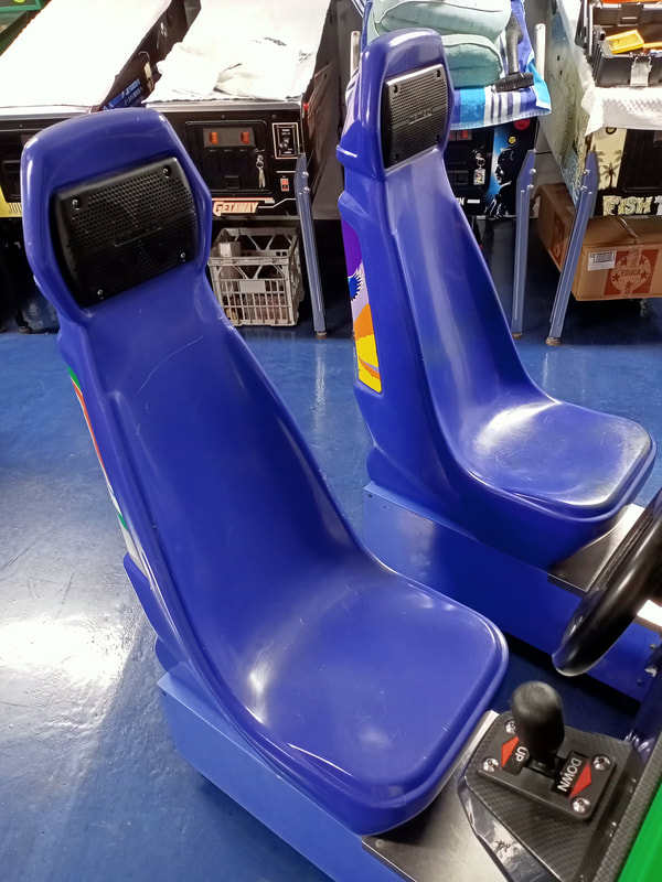
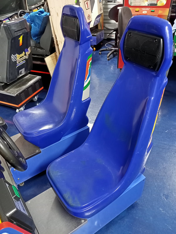
Like most driving games, the seats on this cabinet were absolutely filthy and were a little deformed. The first issue was that I could never get the seats level even though I was sure all of the leg levellers were adjusted to the correct height. The problem was that the levellers had somehow been bent completely out of alignment, so most of them were pointing out from the seat base at weird angles. The effect was most pronounced with the levellers turned all of the way out. Long story short, all of them needed to be adjusted at least a little.
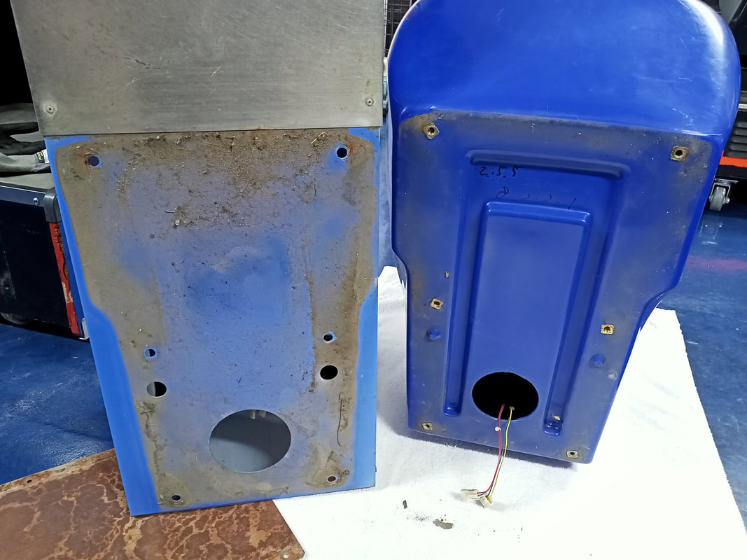
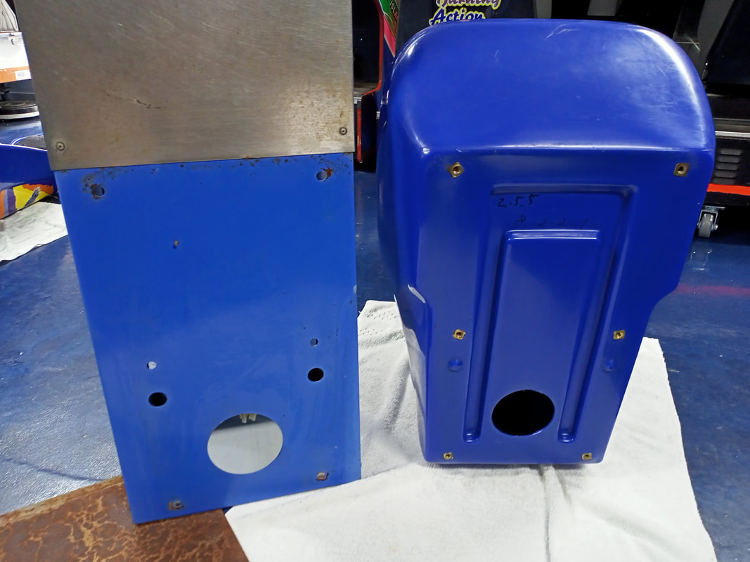
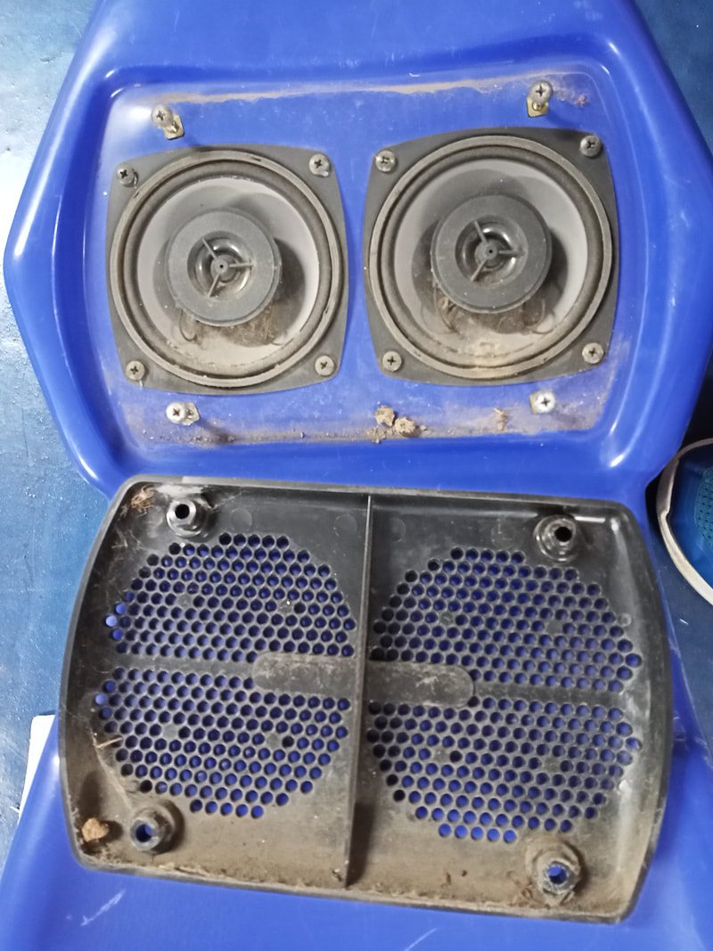
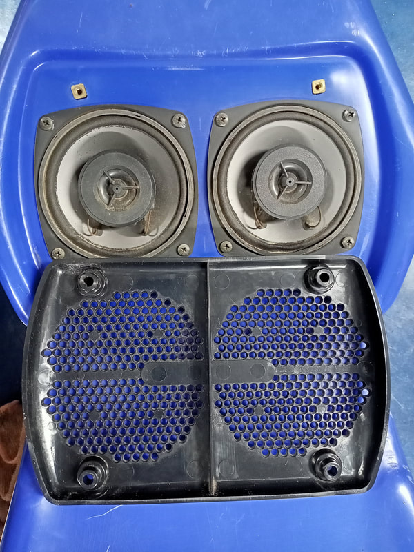
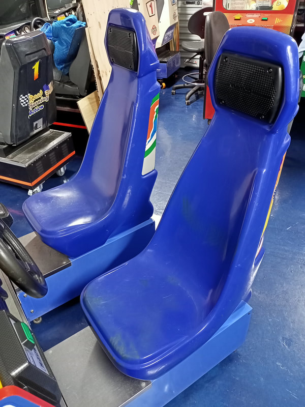
I decided to try flattening the metal around the captive nut from within the base of the seat with a few strikes of a ball-peen hammer. My thinking was that this would (hopefully) pop the metal back out. To access the interior of the seat base, simply unscrew the six screws which hold the metal cover to the underside. This is a good opportunity to give this void space a clean; mine was full of dirt, debris, and even some leaves. Unfortunately, trying to correct the metal with the ball-peen hammer only improved things a little. Time to bring out the big guns. I turned all of the levellers out to maximum length. A liberal application of WD-40 (Bunnings) helped get the levellers loose and moving nicely. Then, I simply bashed them back into position with a mallet. After a few strikes on each leveller, they were looking nice and straight again. Thankfully, no broken welds on the captive nuts, either. Next port of call were the seat bases. These get pretty grimy, and need to be taken apart from cleaning. The plastic seat attaches to the metal base via six bolts. Disconnect the connector for the speakers, and the base and seat can be separated. After a clean, they were looking much better. While I had the seat in pieces, now was a good time to clean out the speaker housing in the headrest. Undo the four screws which hold the plastic cover in place, and you'll have access to the speakers. The speakers weren't to dirty on this cabinet, and all speakers were working properly. The decals on the rear of the seats were a little damaged, but I opted not to do any work on these. Unfortunately, replacement decals are unavailable so repainting or recreating the original art is the only option. Inconsistent game booting
This was a slightly trickier issue to troubleshoot as the problem seemed to come and go. The symptoms of this problem presented as a lack of anything on the monitor, even though the topper lights lit up as they should. The issue occurred randomly, and on several occasions I would open the cabinet, adjust some connectors or move things around, and the problem would disappear. I initially put it down to a dodgy connector, but after inspecting and reseating all of them, the issue persisted. Time to take a closer look.
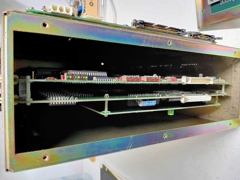
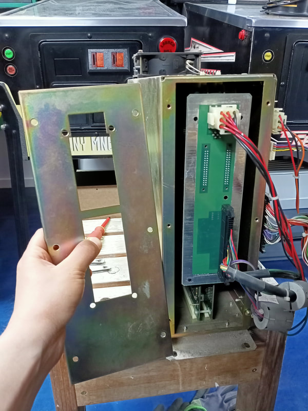
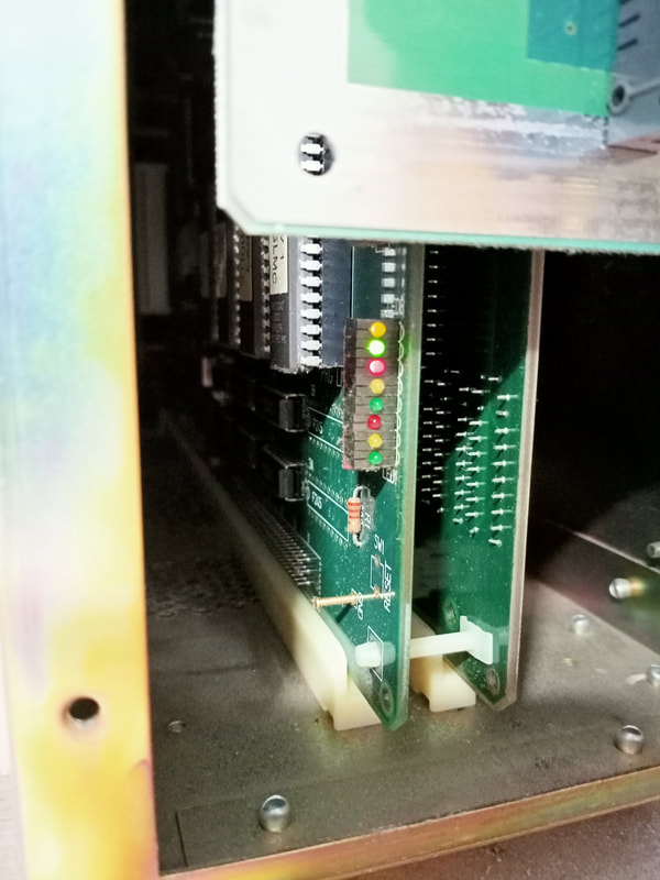
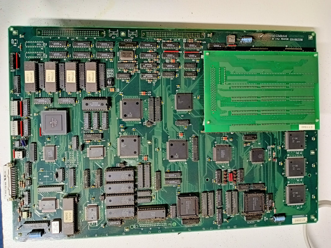
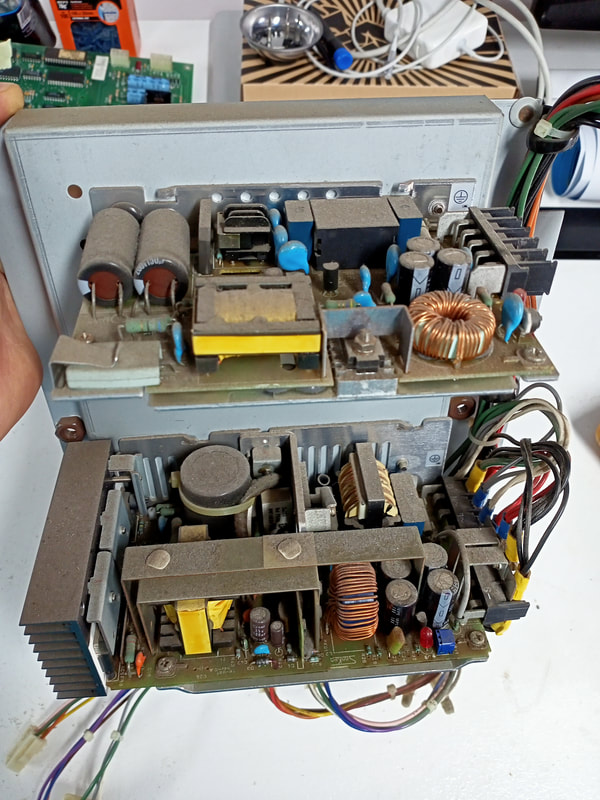
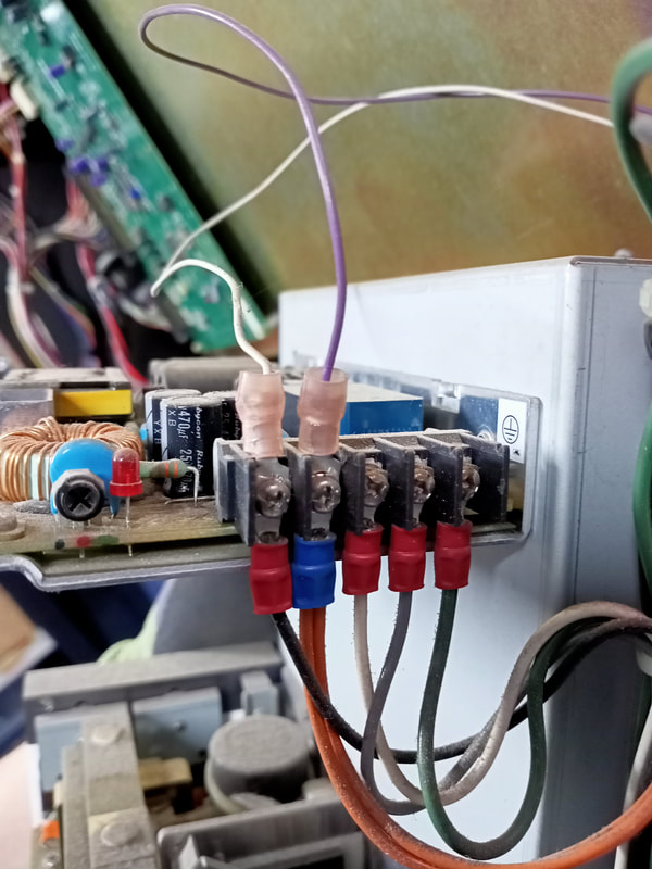
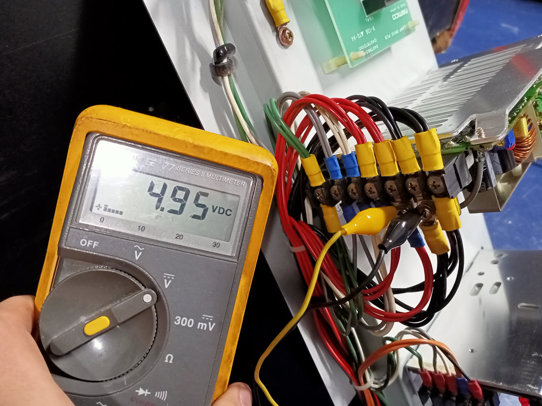
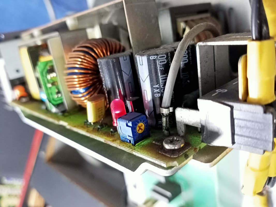
With the cabinet open I took note of exactly what was happening when power was applied. I could hear the monitor tubes turning on, and I also saw the fans attached to each of the board cages spinning. So, we definitely had power getting to the cabinet. I assumed the monitors were OK, as they were on, but were just blank because they weren't receiving any signals. The only reason I could think of for that would be an issue with the game boards. Time to take a look inside the board stack cages. Each cage is bolted to the cabinet with two bolts. Once those are undone, disconnect the fan connector (top of cage), the I/O board (4 connectors), and the EMI filter board (2 connectors). There will be one ground wire connected to the cage via a screw as well; don't forget to undo that one, too. Each player is controlled by a board set comprising of six boards mounted to, or within, the board cage. This includes a single board mounted to the exterior of the cage (I/O PCB), and boards within the cage (CPU board, point ROM PCB, video PCB, video ROM PCB, and EMI filter board). The EMI filter board is the one at the proximal end of the cage, attached to the removable cover. To access the boards within, remove the six screws attaching the cover to the rest of the cage. You'll have to give the cover a bit of a tug as the EMI filter board is mounted to the cover. The EMI board itself is attached to the CPU and video PCB via two connectors, so try to apply even pressure to the cover as you lift it off so as not to damage these connectors. Now that I was in, I could do some digging to figure out what was (or was not) happening. The first thing to check is the status of the eight LEDs on the CPU board. These normally flash in sequence to indicate a successful game boot, as in the video below. To check what the CPU board was doing upon power on, I removed the EMI board from the board cage cover/faceplate, and plugged it back into the CPU board and video PCB. This allowed me to connect power and the other game boards to the EMI board, while keeping the cover off so I could observe the LEDs. No bueno! I could see a couple of the LEDs lit, but they were not going off and on in sequence to indicate the boards were running properly. I removed the boards to see if anything was visibly wrong with them, but they seemed OK. I reinstalled the boards back into the cage and, while I was at it, gave the fan and cage grille a clean as well. There was plenty of dust and debris inside the fan housing as well as the cage grille. Clearly, there was an issue with the boards booting up normally but based on the fact that both board sets in the cabinet were having the same issue, I suspected the issue was upstream rather than a problem with the board sets themselves. There are only a couple of things upstream of the boards in System 22 games: the power supplies, and the transformer. First port of call were the power supplies. System 22 games use two main power supplies, which are powered by 110 volts direct from the transformer. These power supplies are mounted to a metal plate in the centre of the cabinet. The power supply at the top is the 12-volt supply, and the one on the bottom is the 5-volt supply. To make testing easier, I removed the metal plate from the cabinet so I could have better access to the power supply boards. If you do this, you can disconnect the white and purple wires from the 12 volt power supply to give you more space so you can manoeuvre the metal panel outside the cabinet. Apart from being a little dusty, the power supplies looked to be originals and in good order. I checked the fuses on both power supplies and they were intact. Next step was to test the output from each power supply and verify that they were working properly. The wire colours make it easy to tell which wires are which (black for ground, red for 5 volts, orange for 12 volts). The 12-volt supply had no issues and was pushing out a consistent 12 volts. The 5-volt power supply was not so good. It was only pushing out 4.95 volts. Namco games are very picky about their supply voltages, and anything below a nominal 5 volts will produce issues. There is a voltage adjustment potentiometer on the power supply board. I turned this a little until the output was steady at about 5.1 volts. I put everything back into the cabinet and turned the game on to test. Both board sets booted up! Looks like a low 5-volt circuit was the cause of the issue. If turning the voltage up did not fix the issue I would have started refurbishing the power supply, particularly replacing any capacitors which may have leaked or run dry. Old capacitors are often the cause of temperamental power supply outputs. Steering wheel badge replacement
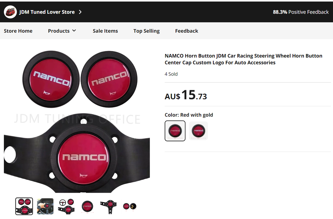
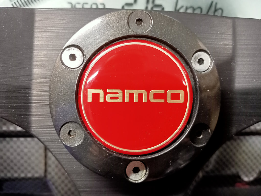
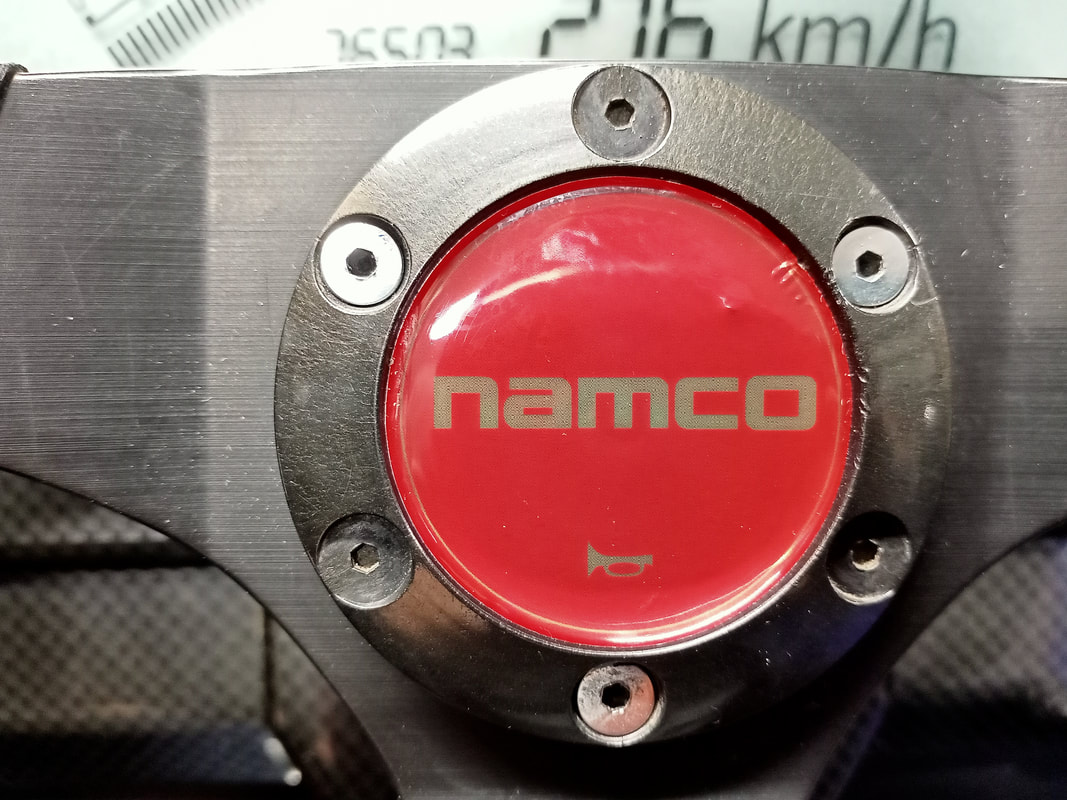
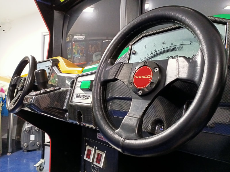
The steering wheels each have the Namco logo in the centre of a red domed label, which is a decal covered with a polyurethane coating. These look really nice, but unfortunately, one of the steering wheels was missing the decal altogether. I thought about removing and then scanning the one decal that was still present, but I didn't want to risk damaging it, and I wasn't sure I would be able to get a good scan due to the domed shape of the decal.
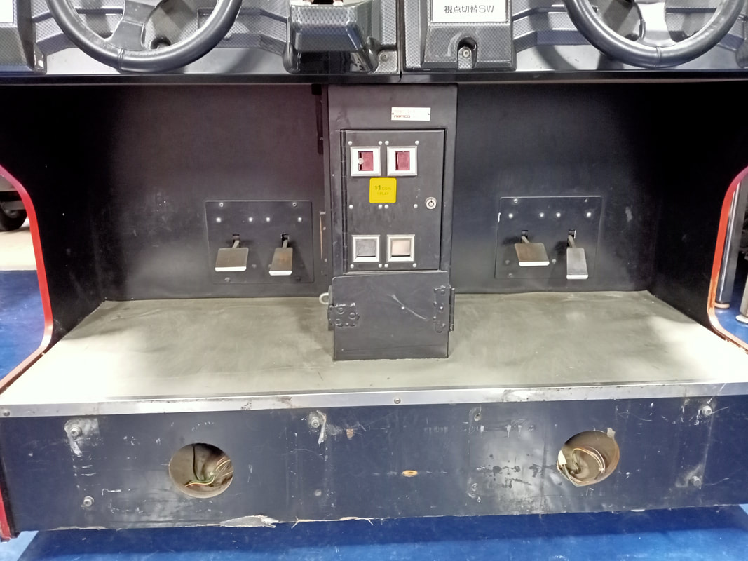
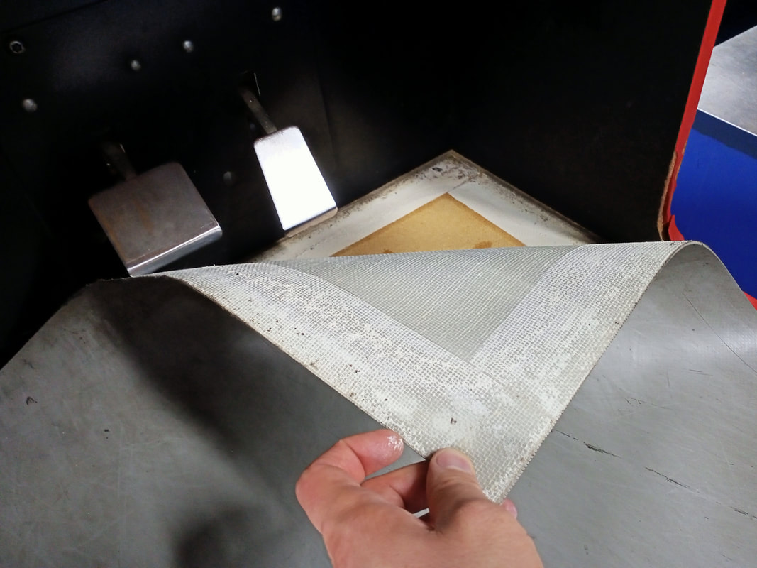
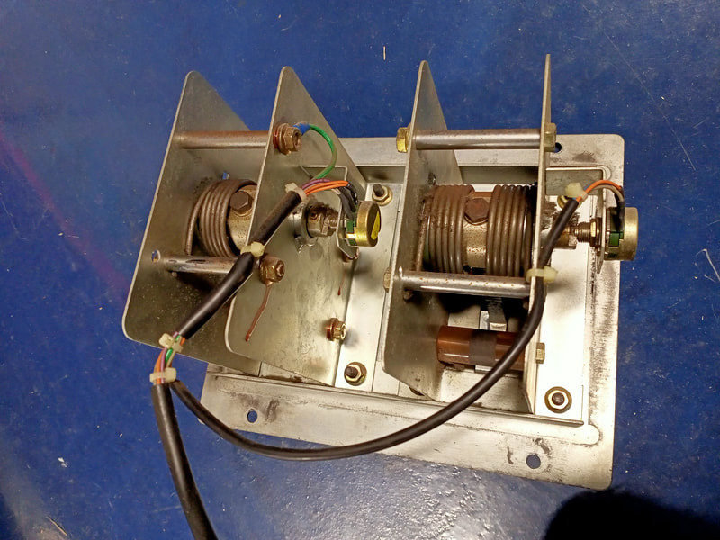
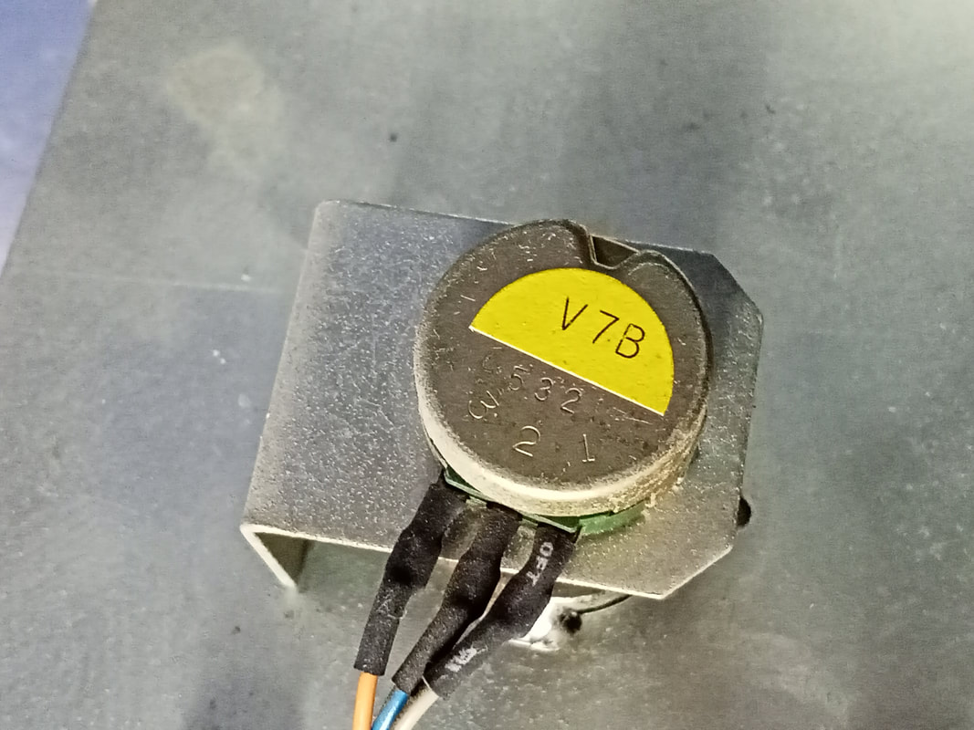
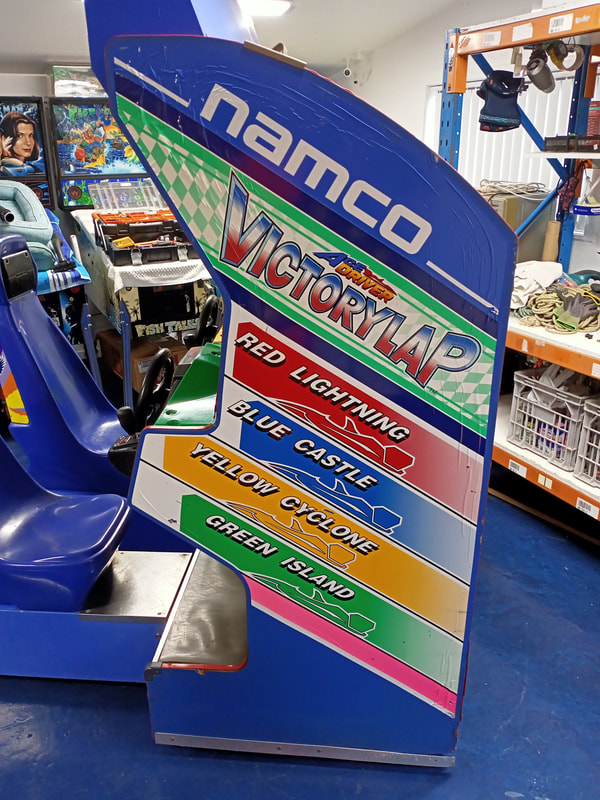
To my surprise, I actually found a reasonable replacement on Aliexpress, almost by accident. I was searching for anything with "namco" in the title, and this listing popped up. This seller sells a bunch of mods and accessories aimed at Japanese cars, one of which was this steering wheel sticker and horn button which looked very similar to the one I was trying to replace on Victory Lap. It's not often you find a replacement arcade machine part readily available like this, so I asked the seller if they could do a custom size for the sticker, and sell the sticker on its own without the button assembly. They agreed, but the minimum sticker size they could do was 43.5mm diameter, which looked like it was just the right size to fit within the centre bezel of the steering wheel. At $26 it wasn't a cheap, especially considering what it was, but for the ease of a plug-and-play part, I decided to bite the bullet and order it. The seller sells two colours - silver and gold. Make sure to get the gold as this will match the original logo colouring. Turns out, the decal was the perfect size. The coating on the topside of the decal is also similar to the original, which was a good result. The decal itself does look a little different to the OEM one, but I wasn't expecting perfection here. The letting is slightly less reflective and more grainy than the original, so it doesn't "pop" quite as much. There is also a small horn symbol on the decal which isn't on the original. There was some kind of imperfection in my decal as well, which made it look as if there was something stuck under it. All things considered, I was just happy there was a part available that could replace the original decal which was the correct size and looked the part. Reassembly Follow the disassembly steps from above in reverse to put everything back together. Most of the assemblies on Victory Lap are modular (dashboard assembly, gas and brake pedals, etc.), so they can be removed from the main cabinet to work on them, then put back in one piece. You will probably need to replace the M8 bolts that secure the seats to the main cabinet. The bolts on my game were old and rusty. A few new ones (Bunnings) with a bit of WD-40 applied to them to clear out the threads did the trick. One other part of the cabinet you may wish to repair or replace is the floor beneath the pedals. On my cabinet, this was a boring grey vinyl which had started to peel in a couple of places. This is only stuck down with double-sided tape, so I glued it back down with some construction adhesive. However, this floor would be a great contender for replacement with a sheet of shiny new checker plate/tread plate. Of course, you'd need a fairly big sheet which would cost a few hundred dollars, but it would be a big improvement over the original. The gas and brake pedal assemblies were in good working order on this cabinet, so they simply got a clean before being reinstalled into the cabinet. The main part you'll need to worry about replacing on these is the potentiometer. There is one for each pedal. Apparently some are still available to purchase (SuzoHapp) however these don't appear to be the right ones, as I measured the pots in my game to be 470 ohm. Luckily, both of the monitors were also bright and colourful with a good quality picture. I didn't need to do any servicing of the monitor chasses in this case. The monitors are 29" Toshibas with MS9-29 chasses; good quality units. I expect these will last quite a while longer before needing a service. Conclusion My work on Cyber Cycles last year prepared me well for Victory Lap as I was more familiar with System 22 cabinets and the components within. This was actually my first time tearing into a twin driving cabinet properly, as I haven't yet started the restoration of my Daytona USA (Sega, 1994) or Sega Rally Championship (Sega, 1995). Luckily for me, there was not a huge amount to do to the steering assemblies or the pedal assemblies apart from cleaning them. By virtue of the fact that it was released at a similar time, many people with compare Victory Lap to Daytona USA. A lot of people have fond memories of playing Dayonta because it was everywhere, but not as many people have ever tried Victory Lap. I was in the same boat until I got this game. I think Victory Lap gives Dayonta a good run for its money in terms of driving feel. Daytona definitely has a more "arcadey" feel to the handling of the cars, whereas Victory Lap feels a little more realistic. In particular, the harder difficulty modes make it much more difficult to control the car, especially around corners and when going at speed. Spinning out is much more frequent unless you brake and are sensible with your gear changes. People more familiar with racing will probably appreciate this more than the pump-and-go tactics that are more suited to Daytona. The game looks nice in terms of the graphics, and the sound and music also suit it well. There are three tracks to race on, and with a combination of difficulty levels and transmissions, there's a lot of replayability for driving game. This game will probably be up for sale soon, so keep an eye on the Machines for Sale page for details. Below are some photos and video of the game after the restoration was complete.
0 Comments
Leave a Reply. |
About
Here you will find logs of our pinball and arcade machine restorations, repairs, discussion about general pinball and arcade topics, as well as recounts of our random pinball adventures.
Check back regularly for updates! Blog updates
Archives
May 2024
Categories
All
Donate

Running this website is a hobby for me (just like pinball!). I like being able to show off my restoration work so everyone can learn from it and potentially fix their own machines. If you enjoy reading the site's content or it has been helpful to you, please consider donating to offset some of the website's operating costs. |


 RSS Feed