|
I've been repairing a few classic Bally games lately, so it's only fitting that this one came into my care recently. Star Trek (Bally, 1979) has some cool playfield features including a saucer which spits the ball out into the pop bumpers, and a free ball return lane. Star Trek appears to be the only Bally solid state game that had a free ball return lane feature, and it was a great way to rack up scores by collecting bonuses continuously. The "Where No Man Has Gone" horseshoe at the top left of the playfield was also a cool gimmick, causing the left pop bumper to fire the ball back at the left flipper. This will be a relatively short blog post as this restoration was focused mainly on circuit board repairs and upgrades. Only minor playfield repairs were conducted, and the machine was otherwise in good, playing condition. The playfield was stripped and cleaned, various broken parts were replaced, and the flipper assemblies were also rebuilt. However, there's nothing particularly exciting about any of that. Instead, I intend for this blog post to serve as a generic reference for those troubleshooting classic Bally boardsets and to explain some of the basic modifications and upgrades I perform. The game went through my standard restoration process to get it playing and looking like new. The repair and upgrading of each of the circuit boards is described in the sections below. Tips & Troubleshooting (click on sections below to view details) Rectifier board repairs
So, let's go back to where it all began (where we get power, that is!). And the place where we get power, and most of the problems associated with it, is the rectifier board. I've never had an issue with any Bally transformers before, but for those who require one, they are now being remade and are readily available (PSPA). However, the transformer on this game was fine. The power cord on this game was also intact and in good condition, so there was no need to replace it. However, you can get these easily should you need one. Simply buy an extension cable and cut off the female end (Bunnings, Jaycar).
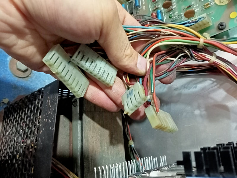
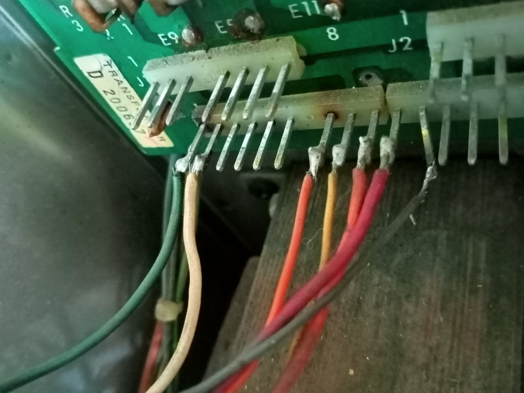
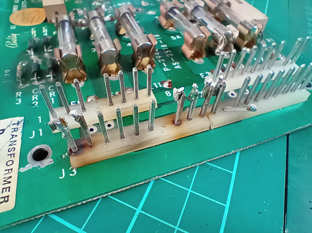
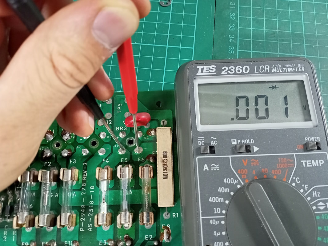
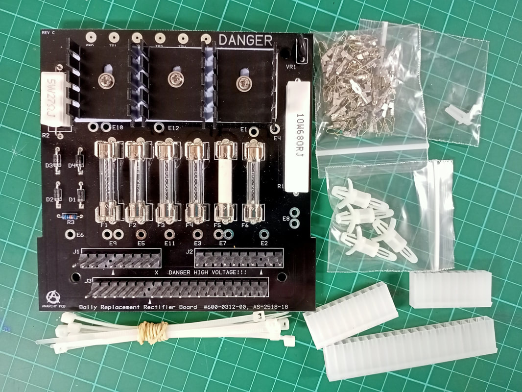
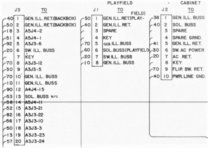
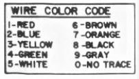
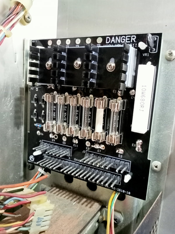
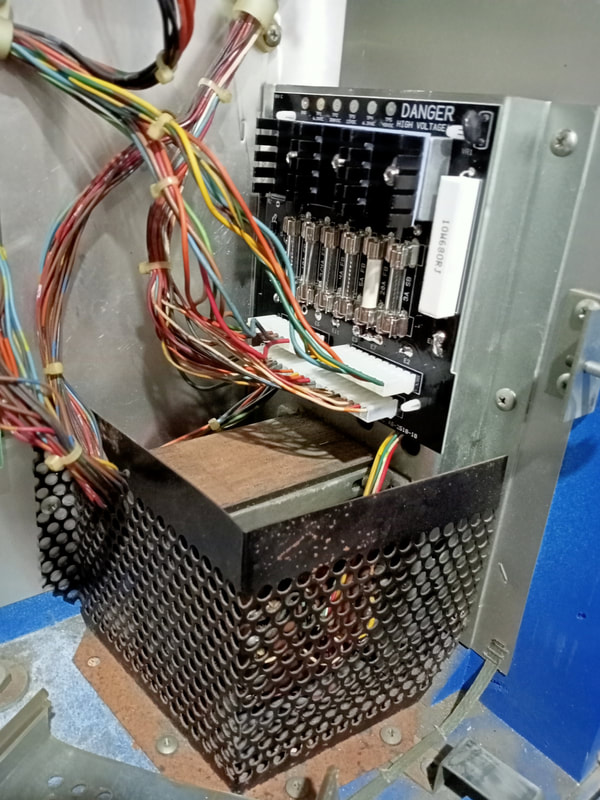
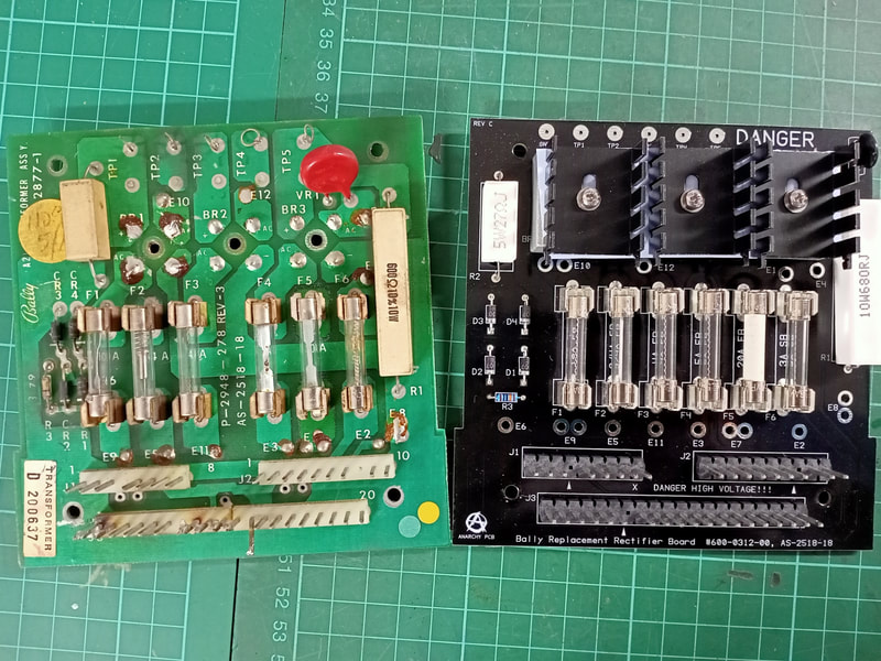
The title of this section is a bit of a misnomer. That's because with most rectifier boards, it's more an issue of replacement rather than repair. Don't get me wrong, it's certainly possible to refurbish original rectifier boards and I have done so in the past. The process is explained well in a few different resources including Pinwiki and Clay's guides. However, I've found that it is often easier to simply install a brand new rectifier board. There are boards available from various manufacturers and they all perform superiorly compared to the original, tired circuit boards. Plus, you get brand new connectors and crimp terminals with most new boards, so you can be assured that every part of the system is brand new and working as it should. The rectifier board in this Star Trek was blowing fuses (specifically, fuse F6), preventing the game from booting up properly. Visually inspecting the board, the biggest issue were the connectors. They were destroyed, with some having been damaged by heat damage. Some wires were soldered directly to the terminal pins, too. While messy, the wiring situation was not the cause of the blown fuse. F6 fuses the AC input to the rectifier board from the transformer. This doesn't really help narrow things down much, but suggests some component has failed and created a short somewhere on the rectifier board. The resistors and varistor on the rectifier board tested OK, and there's not much else in the circuits on this board except for the rectifiers. With blown fuses, I always suspect the bridge rectifiers. These are driven to their limit and are now over 40 years old. Sure enough, one of the diodes in BR3 had shorted internally. This is what was causing F6 to blow. Instead of replacing the rectifier on its own, I decided to replace the entire rectifier board with one of the many readily available reproduction boards. When working on a Playboy recently I used a Homepin rectifier board, which was a good unit. This time, I decided to try out a different manufacturer and purchased one from Anarchy PCB (RTBB). This is the brand of replacement pinball PCBs supplied by Pinball Life. The Anarchy PCB kit contains everything you'll need. There are plenty of 0.156" crimp terminals so if you screw up a few crimps, you'll have spares to try again. The zip ties are a nice touch and help to keep everything neat once you reassemble. New board mounts and polarizing pins are also included. Plus, the connectors include a full-size, 20-pin connector for J3! I prefer this over the Homepin board, which provided two 10-pin connectors. All fuses come pre-installed. Installation of the board is pretty straightforward, with instructions advising you of what colour transformer tap wires go into which through holes on the board. The through holes are large-diameter, with thick solder pads. This is great for the thicker transformer tap wires, and also handy for when you are doing this kind of board replacement on site and may need to use a higher-wattage soldering iron (like I was this time!). Bigger solder pads dissipate the heat more evenly and are more forgiving. Through hole numbers are silkscreened on both the solder and the component side of the board, which is a great timesaver when swapping wires over. I like to transfer one wire at a time from the old to the new board to make sure there are no mistakes. Once everything is soldered into place, simply fit the board onto the transformer mounting plate and onto the supplied board mounts. The last thing to work on are the connectors. The crimp pins supplied with this board kit are Trifurcon-style crimp terminals. These are the recommended crimp types to use, especially on connector J3 where the current draw is greatest when using incandescent lamps. One by one, cut each wire from each connector, strip it, crimp a new terminal onto it, and install it into the new connector. This is the easiest way to make sure you don't mess up the wiring. However, if you forget, or the wiring is a rats nest to start with, you can refer to the Bally schematic manual. The wire colours are indicated to the left of each connector, with a two number code representing each wire colour and trace. Don't forget to add the polarising pins, which are included in the kit, and vital for making sure you install the connector the right way. Overall, I was impressed with the Anarchy PCB board and would recommend it over the Homepin version mainly due to the inclusion of Trifurcon crimp pins as well as a 20-pin connector for J3. Otherwise, the board appears to be well designed with upgraded components installed (including larger bridge rectifiers with heatsinks). Once the new rectifier board was installed, the game booted up without issue. So forget about troubleshooting the heat stressed and seriously under-specification original rectifier board, and just replace it with a new one. It's worth it for the time you'll save messing around with individual components alone! Solenoid driver board repairs
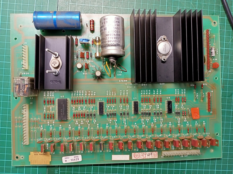
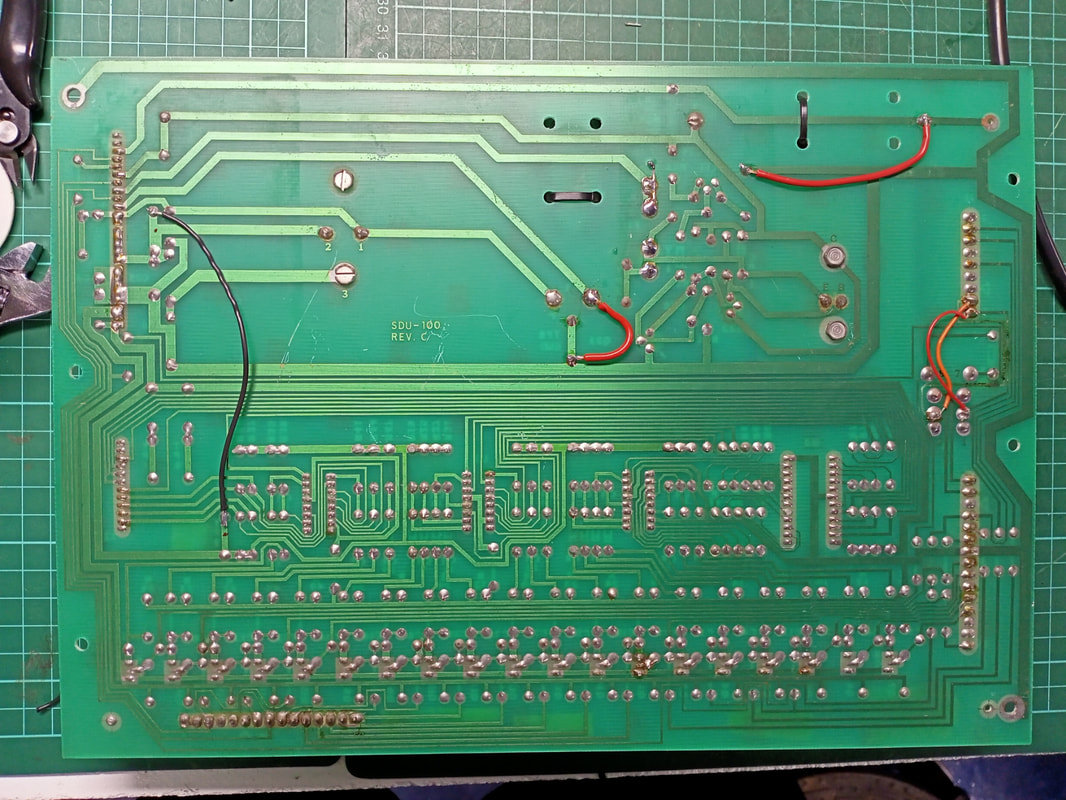
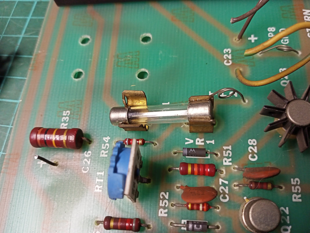
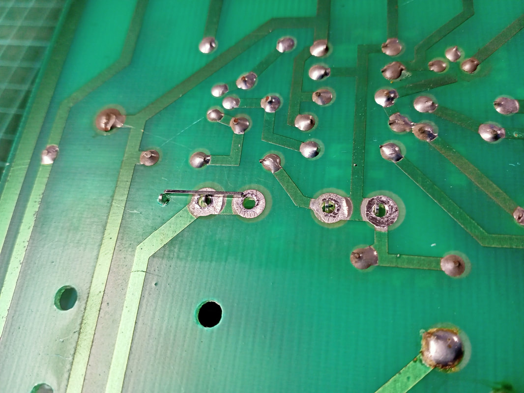
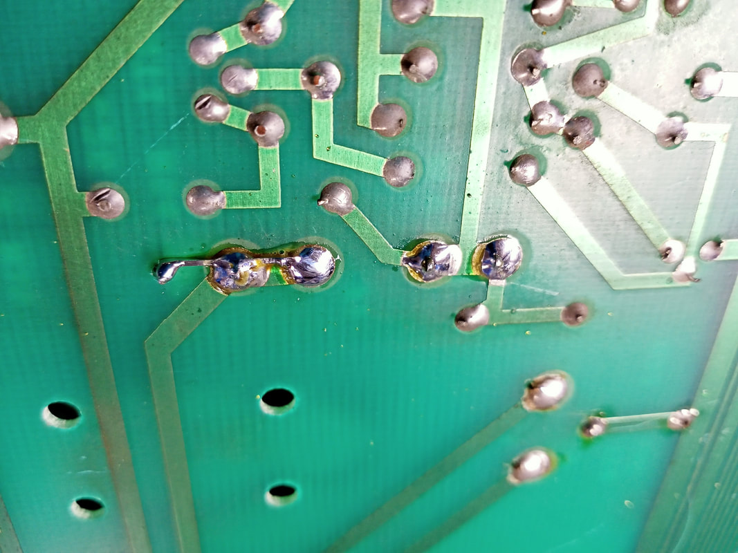
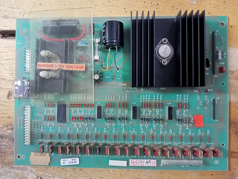
This solenoid driver board appeared to be working well, but the components were all original, so a few upgrades were in order. The components to upgrade are well documented on Pinwiki, as well as Clay's repair guides. The first thing I did was check that all resistors, diodes and other discrete components in the high voltage section (under the plastic guard) were within specification. They all appeared to be OK, so no replacements were needed there. C23 and C26 were first up for replacement. Luckily I had some capacitors in the tool box which were good replacement values. C23 is best replaced with a capacitor with higher capacitance and voltage ratings. I used a 15,000 uf, 25 v capacitor (RS Components, element14). C26 was also replaced with a differently rated capacitor. I used a 150 uf, 400 v capacitor this time (RS Components, element14). Anything from 150-180 uf and over 350 v will suffice as the original specification is hard to find. The next upgrade to was to add some grounding to the new capacitors. The negative leads of C23 and C26 were connected to ground via some jumper wires. Use your multimeter to find the nearest ground trace, as different revisions of the board have them in slightly different spots, and Bally boards are slightly different to Stern boards in how they are laid out. One other jumper was added to connect TP1 and TP3 (both 5 volt test points) to ensure a weak connector or crimp pins at J3 didn't cause issues on the 5 volt circuit. The header pins at J3 were also replaced with brand new ones (RTBB, RS Components, element14). The 0.100" crimp pins in the matching connector housing were also replaced (RS Components, element14, PSPA, RTBB). The next fix that needed action was to replace the fuse holder for the fuse at F1. This fuse had been pushed too far into the fuse clip, splaying it outwards. This seemed like a solid connection for now, but would eventually work loose and require replacement. Better to upgrade it now before that happens! Instead of simply replacing the fuse clip, I opted to upgrade the clip to accomodate a larger, 3AG fuse rather than the uncommon and difficult-to-replace 8AG fuse which was originally used. Pinwiki describes this procedure. The problem is that the Pinwiki procedure recommends attaching the new fuse clip by only one solder joint. I like to make sure that the fuse clip (Jaycar, RTBB, PSPA, Austral Amusements) is anchored to the board nice and tight, so I drilled a new hole in the board so that the fuse clip could be anchored by two joints on the solder side of the board. A 2mm drill bit is about the right size for the fuse clip leads. Luckily, the spacing of the 3AG fuse is such that the upper hole of the original fuse clip can be used for the bottom lead of the new fuse clip, so only the upper hole needs to be drilled. Once the hole is drilled, the fuse clip can be inserted. But, before it was soldered into place, I used a solid conductor (in this case a single 0.100" header pin) and laid it between both fuse clip leads. This way, the lead which sits in the new hole can still be securely held in place on the solder side of the board. And that was the end of the solenoid driver upgrades. None of the other components on the board were suspect, and all solenoids worked properly after the rebuild. MPU board repairs
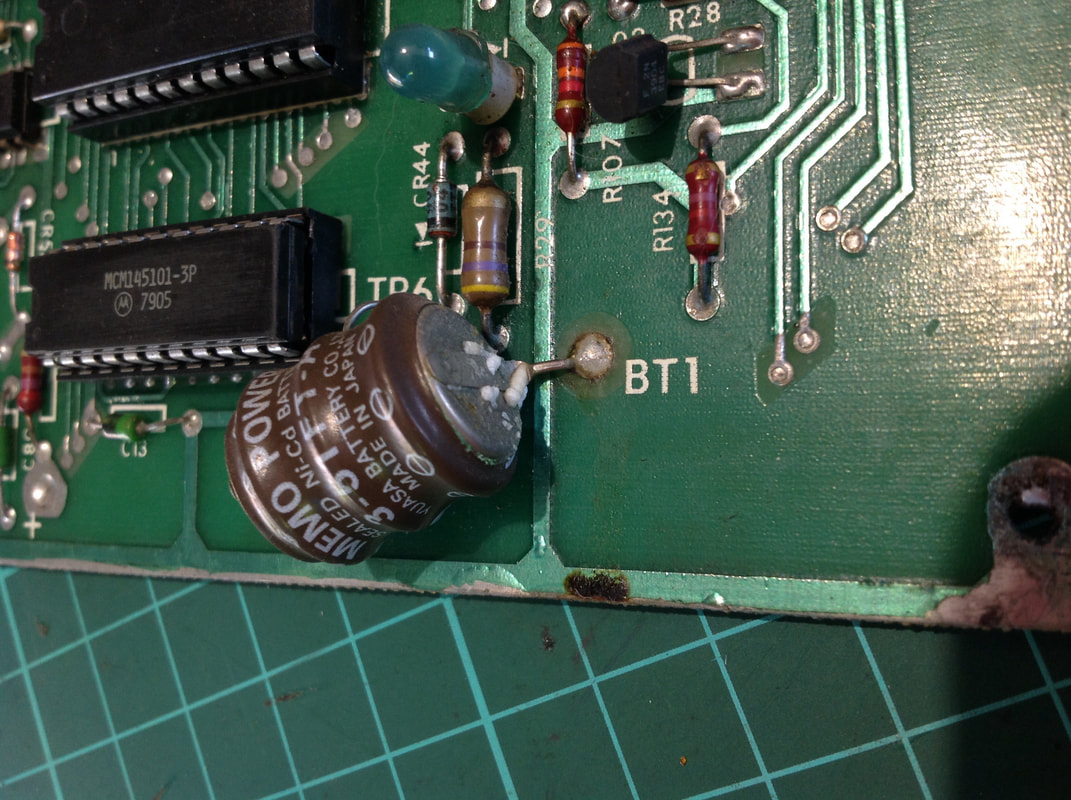
The MPU board was the simplest to upgrade of this lot. All that was needed was a new battery solution. The board had a capacitor battery installed, and it had started to leak. Just in time for replacement!
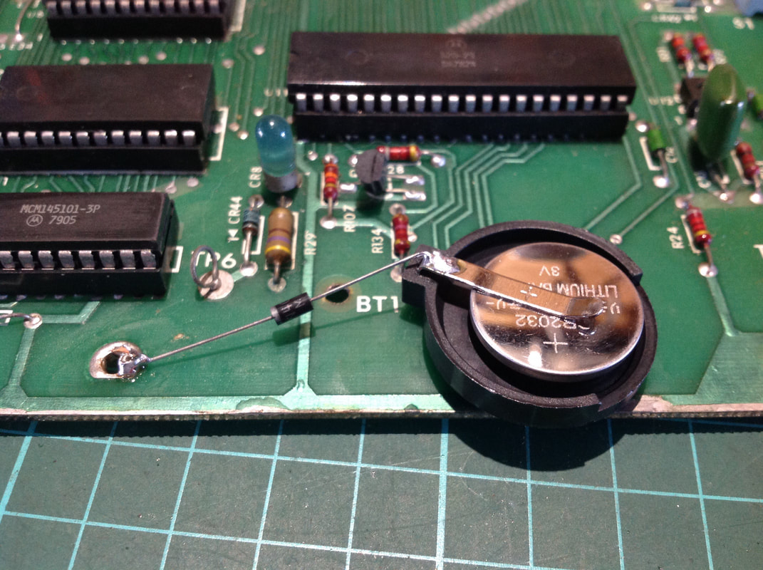
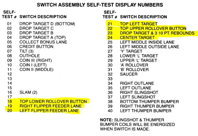
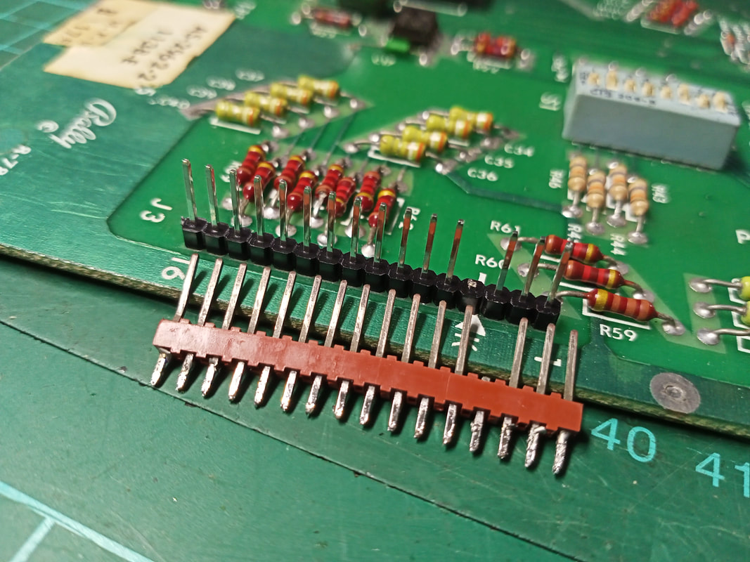
For this board I opted to install a button battery. Luckily, there was only some minor leakage from the original battery which was still mounted to the bottom of the board. There was no corrosion on the board itself, so there was little to clean up. Once the original battery was removed the new battery holder (Jaycar) and battery (Jaycar, Bunnings) could be soldered in. A button cell battery needs a blocking diode to prevent the game from charging the batteries. A 1N4007 diode will work fine for this (Jaycar). Connect this to the positive terminal on the battery holder, with the banded side of the diode facing away from the holder. I like to bend the positive battery holder terminal outwards, such that it can sit on top of the board. You can drill a hole into the board if you like and insert the positive lead of the battery holder through this instead. Be careful about using existing through holes on the board. Only use through holes which have continuity with the positive terminal of the original battery. If you drill your own hole, you'll have to connect the holder to one of these existing through holes with a jumper wire. This can be done on the solder side of the board for a neater install. As for the negative side of the battery holder, this can simply be inserted into the existing negative terminal through holes on the board. Depending on the board there may be a few of these - use whichever allows you to mount the holder in the least obstructive location. The machine was having one other problem originating from the MPU board. A few switches were not registering at all. There did not appear to be any issues with the physical switches on the playfield, and there was good continuity from each switch to the next based on wire colours. To narrow down the cause of the issue I recorded exactly which switches were giving me issues. The manual lists all of the game's switches on page 17, with a playfield diagram indicating their positions on page 18. The affected switches are highlighted in yellow. I noticed that the non-working switches were in sequential order, from switch 18 to 24. This is significant, because it indicates each of the switches are in the same row (return line). Bally switch matrices are arranged in an 8x5 format, allowing for 40 switches in total. A useful resource for working out where switches sit in the matrix is the Bally switch matrix diagram on Pinwiki, which helps visualise where each of the switches are on the matrix. All of my non-working switches were on column 3 (strobe 2). According to the schematic, these all shared a white-blue strobe wire. I confirmed that there was continuity from switch to switch via this wire, and that there was continuity from the switches to the MPU connector at J2 (playfield switch strobes and returns all go through this connector). This all checked out OK. That left the board as the likely failure point. By wiggling connector J2 around on the MPU, some of the switches came to life and would work for a short while before dying again. This was a good confirmation that the problem was the connector pins and header pins, rather than an issue further upstream on the MPU. Replacing the header pins (RTBB) as well as the crimp terminals in the connector (RTBB) got everything working again like it should. I also repinned connector J3, as this services switches on the coin door and cabinet. Lamp driver board repairs
There were no faulty components on the lamp driver board on this game. A couple of lamp issues were apparent, but these were problems caused by the lamps or lamp sockets themselves rather than the driving circuitry.
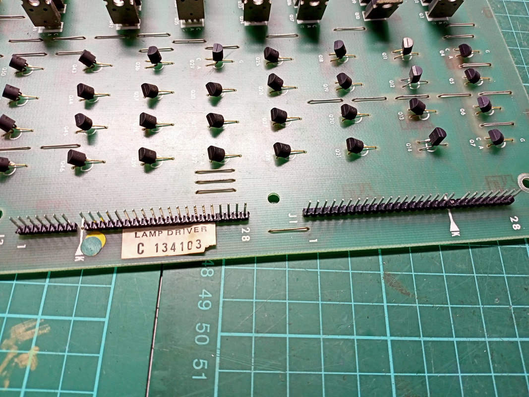
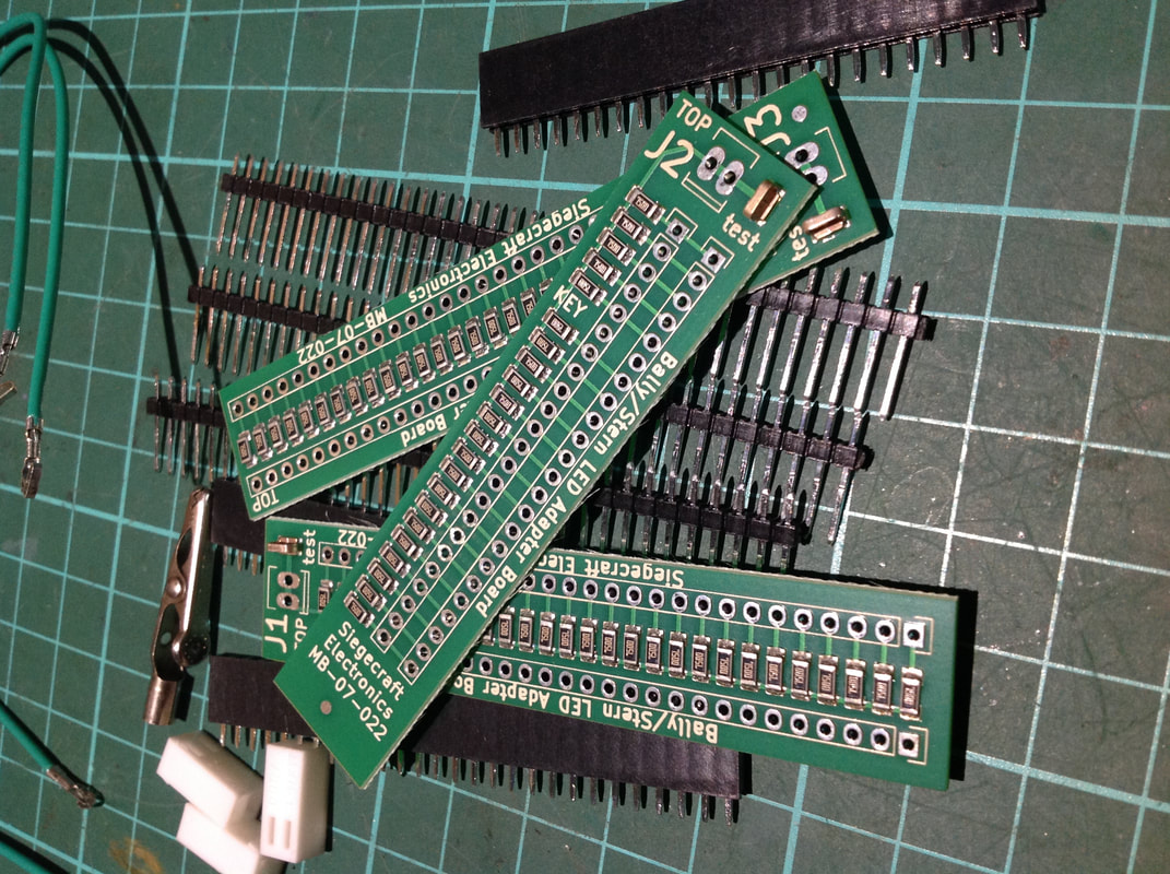
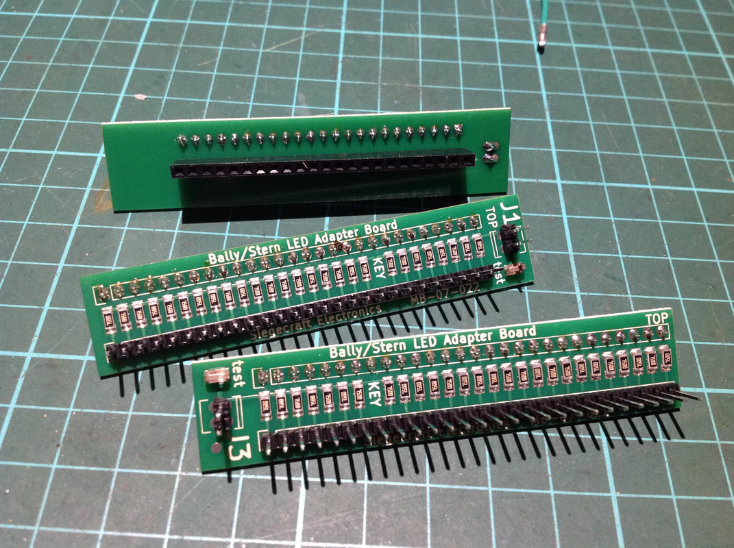
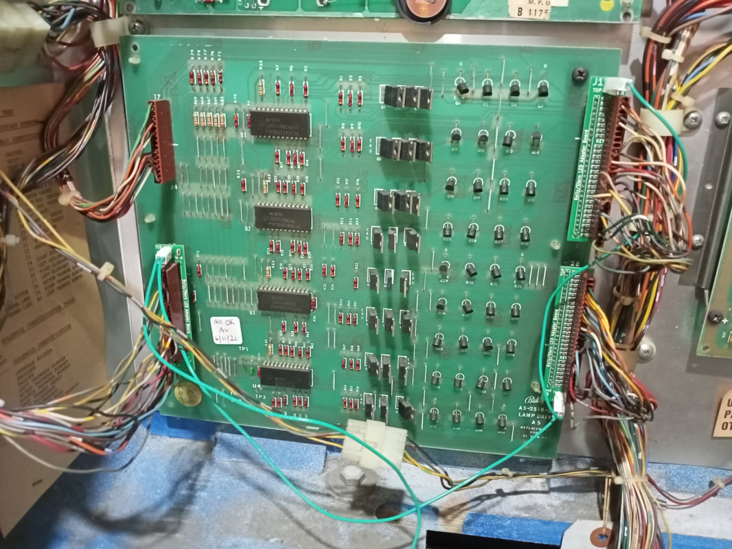
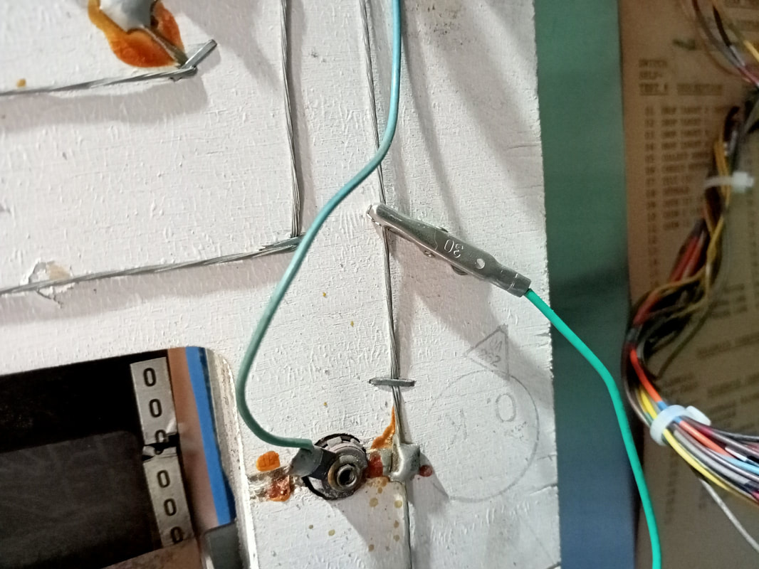
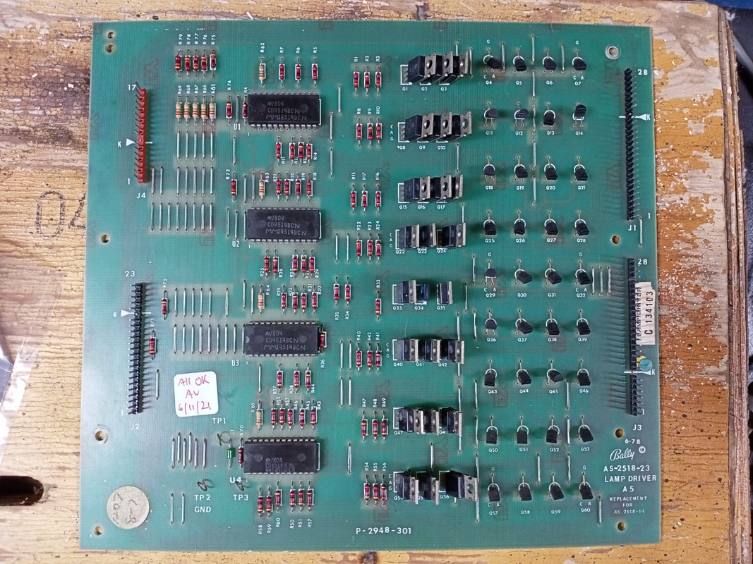
I upgraded all of the playfield and backbox lamps to LEDs. The problem with this is that controlled lamps in Bally games will flicker when LEDs are used. This is due to LEDs drawing so little current compared to traditional incandescent lamps. With so little draw, the lamp board considers the lamp must be off, so it sends a signal to turn the lamp on again. However, it still can't see whether the lamp is on or off, so it repeats the cycle and the end result is a constant flickering which usually renders the game unplayable. General illumination lamps are immune to this, as they are simply supplied a constant voltage as long as the game is on, and are not driven by additional componentry. There are a few solutions to this. You can install an Alltek lamp driver board (PSPA, Austral Amusements). This board incorporates modifications that allow it to work with both LEDs as well as original incandescent globes. A great solution, but also the most expensive one. The cheapest solution is to solder a resistor to each controlled lamp socket in the game. This adds a small load to the circuit, which tricks the lamp driver board into thinking the lamp is drawing more current. While simple, it's a tedious solution as it can take hours to solder a 470 ohm resistor (Jaycar) to each socket. I chose the middle ground option. An adapter circuit board can be plugged into each of the output connectors of the lamp driver board, with resistors built into the board. This has the same effect as the resistor solution above, but without having to manually add a resistor to each socket. Hans at Siegecraft has developed this solution, and he sells three daughter boards which can be fitted into any classic Bally or Stern game and stops the flickering of LEDs in controlled lamp sockets. Several years ago, Vid9000 did a thorough review of these adapter kits. He discusses installation extensively, complete with pictures. A recommended read. The first step in the process after making sure all lamps are actually working, is to replace the header pins on the lamp driver board. The three output connectors at J1, J2, and J3 are the focus here (J4 is an input from the MPU board). The pins at these connectors were all a little tarnished, so I removed them all. I never bother sanding or brushing the pins clean, as this is usually more work and less effective. Besides, you'll probably need to reflow some solder on a couple of the pins anyway, so you may as well replace the lot and know that they are all solidly connected. Terminal strips at 0.100" pitch in various sizes are available (RTBB, RS Components, element14). Once that is done, you are ready to install the adapter boards. When I purchased mine, they were sold as a kit which you soldered together yourself. Now it appears the the boards are only sold as a pre-assembled kit, which makes the process a lot easier (Siegecraft, RTBB). This makes it a plug-and-play solution. Once the daughter boards are installed, the connectors need to be installed. If your kit does not have preassembled connectors, you simply need a 2-way 0.100" connector housing (PSPA, RS Components, element14) and appropriate crimp terminals (RS Components, element14, PSPA, RTBB). Take a piece of insulated wire, install a crimp terminal, and insert into a connector. Plug this into the daughter board at J1. Then, run the wire to J3, and install into the connector here. Then, run another wire from J3 to J2. Now each board will receive power. Lastly, a connection must be made to a common conductor which carries voltage from controlled lamp to lamp. For this, I selected the braid at the rear of the backbox insert panel, as this is easily accessible and connects to each of the controlled lamps on the insert panel. Simply take one last wire, terminate it at the daughter board connector at J2, then run enough length to a controlled lamp in the backbox. Make sure you select an appropriate lamp - you want to look for a game over, tilt, player, ball in play, or shoot again lamp. Not a general illumination lamp! Use an alligator lead while testing, and then solder the lead into place when done. I selected the braid just above the Player 3 insert lamp. Once this was done, we were ready to power up. Everything worked well! An old Bally game with nice, bright LEDs looks really good. Purists will argue that incandescent lamps are more appropriate, and I agree to a point, but the brightness of the LEDs actually helps accentuate the artwork on Star Trek, which is vibrant with red, yellow, and blue tones. Reassembly Once the circuit boards were repaired and back in the game, there wasn't much else to be done! The playfield was stripped, cleaned and checked as per normal procedure. Nothing of note was found during this process. The customer in this case mainly wanted the game to be checked on a basic level and upgraded for better reliability electronically, but he was less concerned about the playfield itself and cosmetic issues with the game such as wear on the playfield and gouges in the cabinet. I'm always happy to work with each customer and their specific goals for repair, so leaving some of the game with its original, worn patina was no problem at all. I enjoyed playing Star Trek. It's a fun game with good bumper action, like most Ballys of this era. Spelling out B-A-L-L-Y is a fun goal, and the saucer at the top of the playfield is a rewarding shot (as is the free ball return lane as discussed at the start of this blog entry). Hearing the game play a tune when you complete B-A-L-L-Y never gets old! This machine should now be good to go for a number of years before it needs any attention (electronically, at least!). Beam me up, Scotty!
1 Comment
Robert Estes
11/5/2024 01:39:49 pm
I have a 1978 Bally Star Trek in excellent physical condition, but some functions quit working recently. Is there someplace that sells or repairs circuit boards?
Reply
Leave a Reply. |
About
Here you will find logs of our pinball and arcade machine restorations, repairs, discussion about general pinball and arcade topics, as well as recounts of our random pinball adventures.
Check back regularly for updates! Blog updates
Archives
May 2024
Categories
All
Donate

Running this website is a hobby for me (just like pinball!). I like being able to show off my restoration work so everyone can learn from it and potentially fix their own machines. If you enjoy reading the site's content or it has been helpful to you, please consider donating to offset some of the website's operating costs. |




 RSS Feed