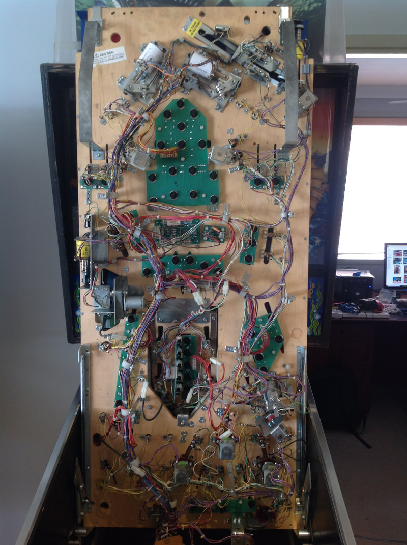
 It's been a while since my last post! Over the last few months, Fiona and I have been busy with a mix of our own arcade projects as well as various repairs for customers, so let's go over one of the recent repairs for another Fish Tales (Williams, 1992)! This customer had not played their Fish Tales in several years and it had sat around not working. The difficult part was that the customer (and the machine) were in Orange, NSW. A bit beyond the typical house call distance! Luckily, he was able to bring the machine to our workshop for the various repairs that it needed. Initial condition report (click on sections below to view details) Cabinet
Good condition overall.
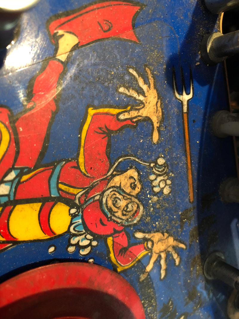
Above playfield
Poor condition overall.
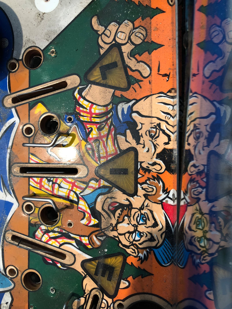
Under playfield
Average condition overall.
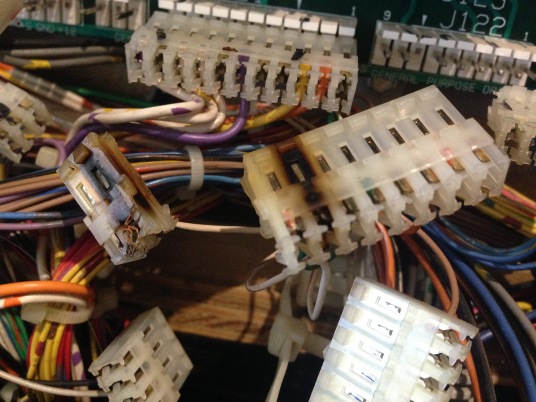
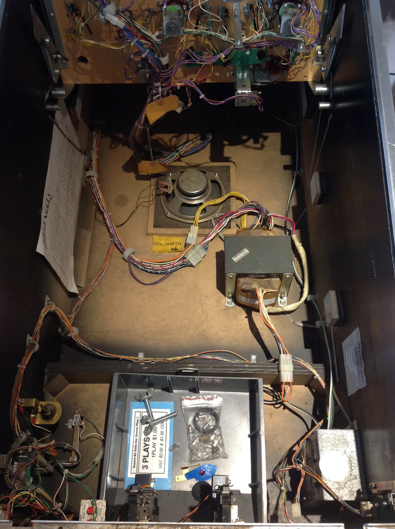
Electrical
Poor condition overall.
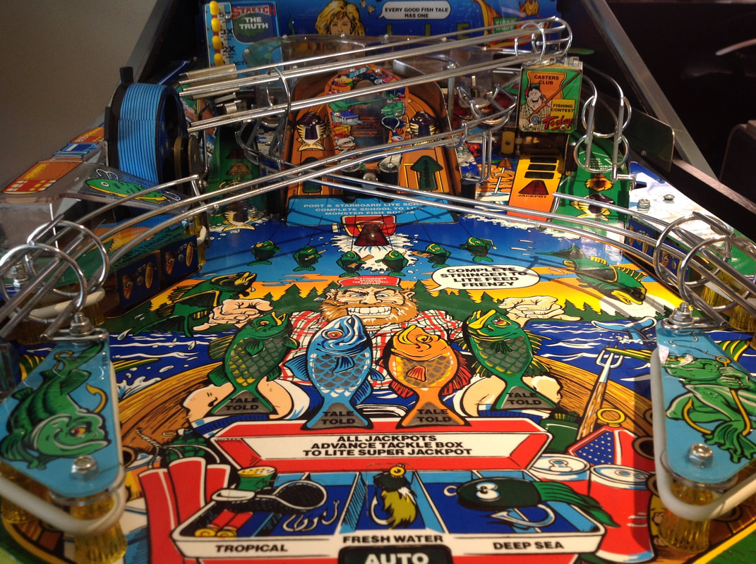
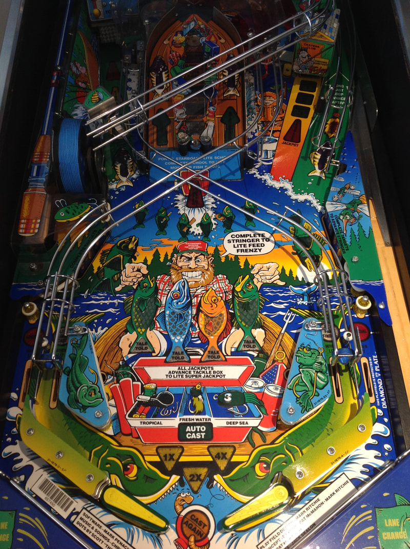
When we first got the game and booted it up, it would not start normally. It displayed an error message intermittently, and when it didn't, it would boot up but start firing coils at random until it was turned off. Definitely not a happy machine! Other than that, the machine was basically complete, but had been neglected for some time. It needed a good clean, thorough check-up, and all of the game startup issues fixed. This restoration turned out to be a good mix of playfield cleaning, servicing coil mechanisms, and electronic repairs. I love a well-rounded restoration! Disassembly I will reiterate what I said in my previous two Fish Tales restorations - I love working on Fish Tales! The simple playfield layout and the simple mechanisms make it easy to disassemble and service. The images below give a rough idea of the condition that the machine was in. The playfield looked to be in good condition under the dirt, with some big, grimy build-ups around the pop bumpers. After disassembly, the game went through my standard restoration process to get it playing and looking like new. During the restoration process, I dealt with a number of issues, described below. Tips & Troubleshooting (click on sections below to view details) Fish topper not flapping
This is an issue I had seen before on my own Fish Tales. The flapping of the fish shakes the topper quite violently, and wires break off the topper coil as a result. That was what happened here, so all that was needed was to reattach the wire.
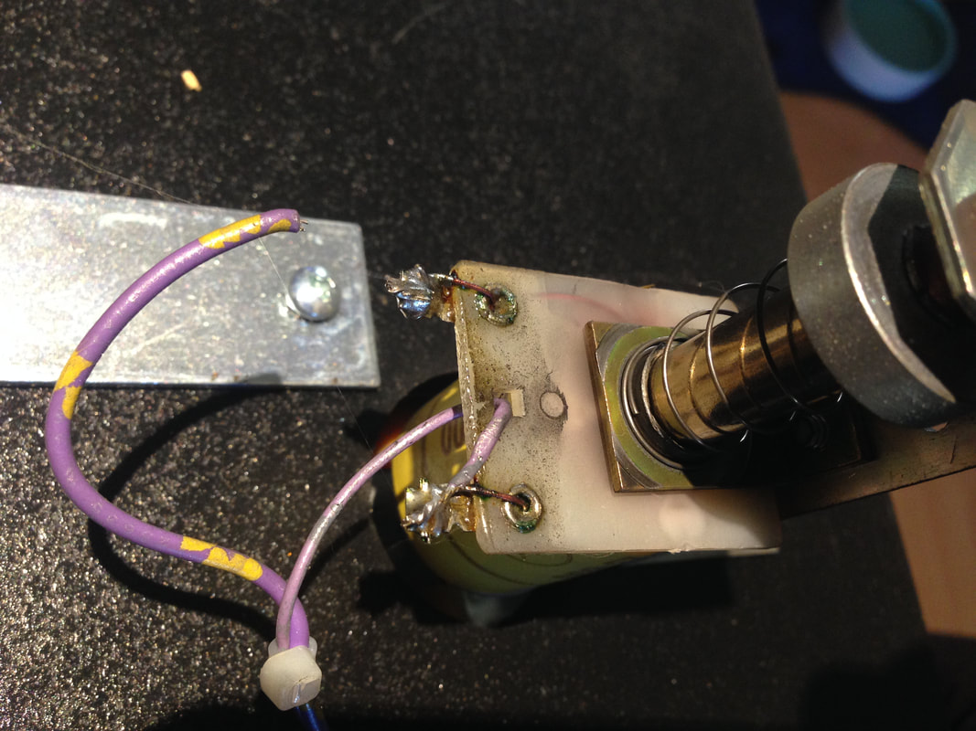
Wire that had become disconnected from the topper coil.
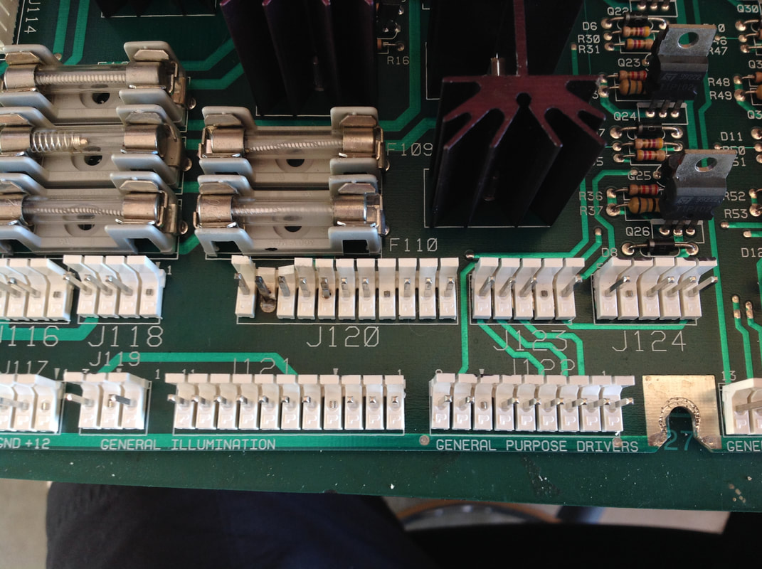
Burned general illumination connector and header pins
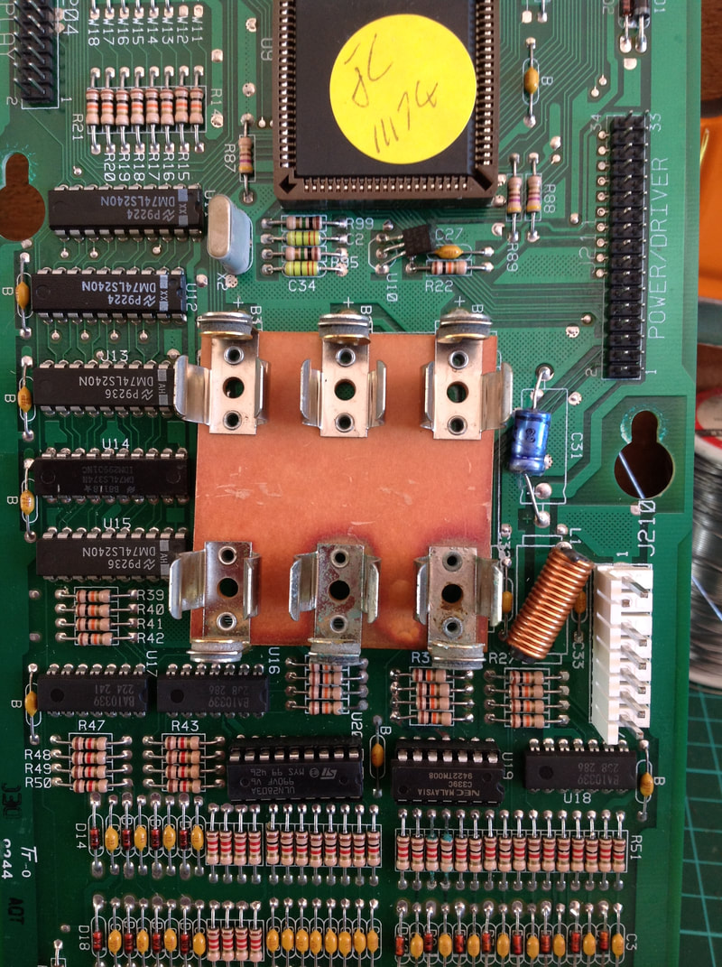
Some of the general illumination lamps were not working on the game, and it was pretty obvious why once the backbox was opened up. Connectors J120 and J121 supply power to the general illumination lamps in the backbox and on the playfield, respectively. There is a lot of current moving through these connections, which results in heat, carbonisation, more heat, more carbonisation and tarnishing, and eventually, a break in continuity. Incandescent lamps are responsible for the burning as they require a fair bit of current to light up. J120 on this game was burned up to the point that the connector fell apart in my hands.
The customer decided to convert the game to LEDs, which was a good idea. This will prevent the connectors burning up in future and will make the playfield look great. First order of business was to replace the header pins for J120. This was easily done by desoldering each of the pins on the underside of the power driver board. My desoldering gun's tip fits neatly over each of the pins, which makes for nice and clean solder removal. In this case, once the solder was removed, the entire header housing actually fell out of the board! There is no cleaner removal than that! Sometimes, you need to forcibly remove the plastic header housing as it can melt and bond to the board surface. Luckily, the damage was not that severe in this case. A new header was installed on the board, and a new IDC connector was installed on the incoming wires to replace the burned one that had fallen apart. Once both of these parts were replaced, the general illumination came back to life.
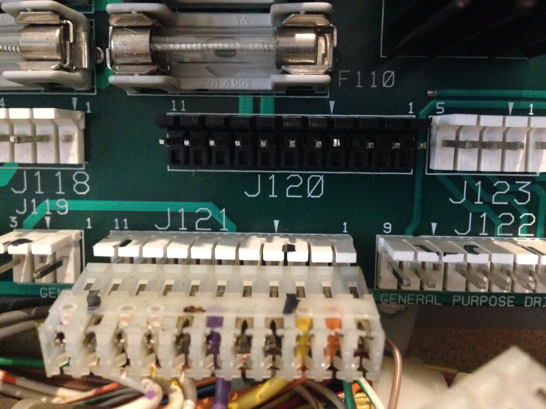
New header pins installed at J120.
Game would not boot properly, or would boot up with errors
This problem materialised in a couple of different ways. When powering up the game, sometimes a message saying "check fuses F114 and F115" would be displayed. These fuses were found to be fine. Other times, the game would boot properly, then it would enter attract mode normally, then all hell would break loose. Random coils on the playfield would go off, flippers would activate, and the menu buttons would press themselves and navigate through the menu system on the display, without me even opening the coin door! Freaky! It was very unpredictable behaviour, but seemed to involve switches that would trigger at random (including the coin door buttons).
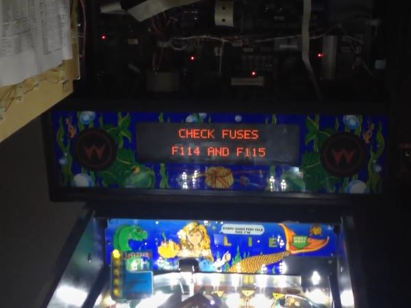
Check fuses F114 and F115 message.
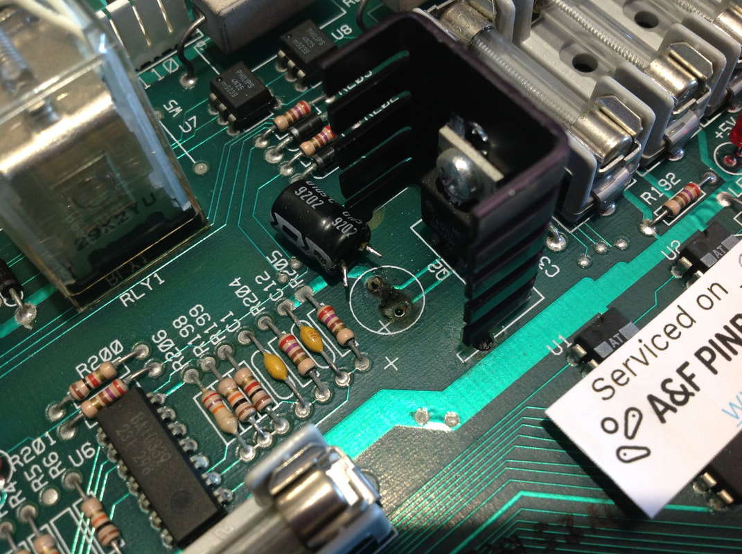
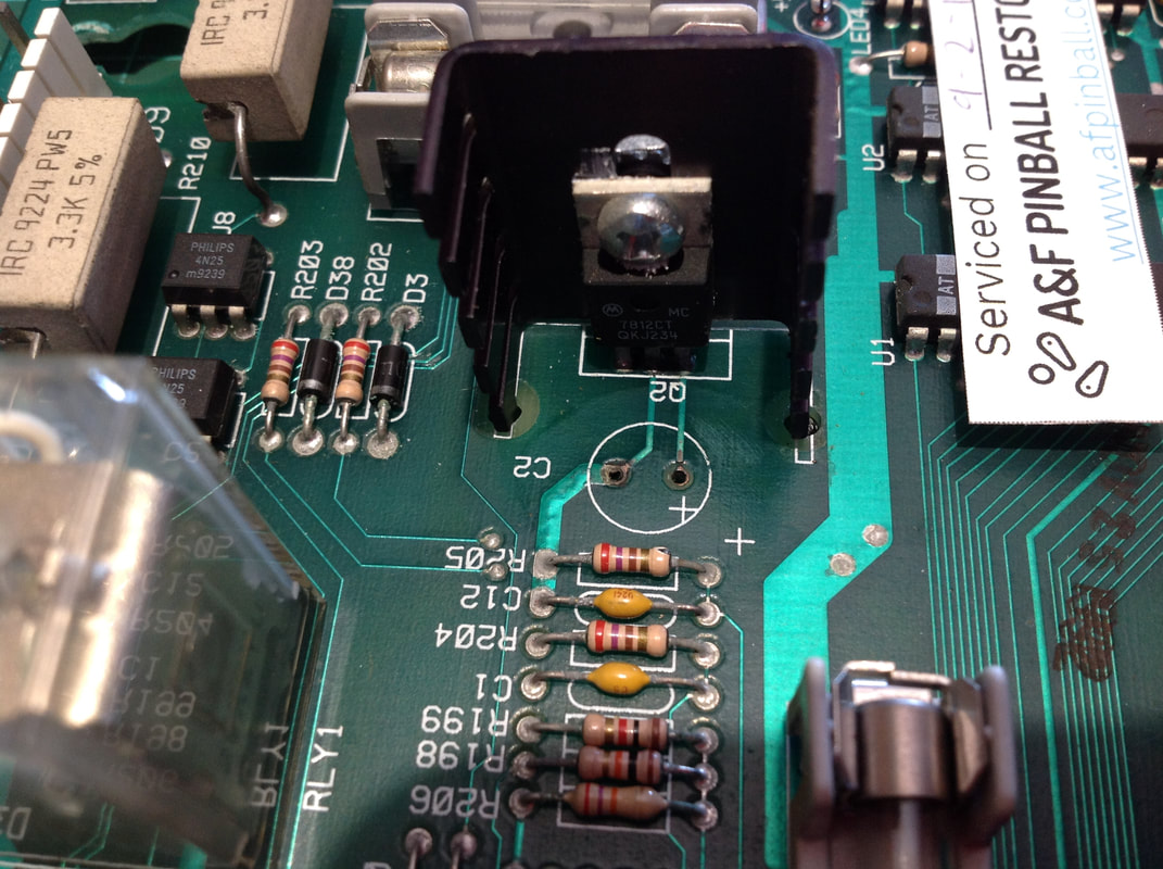
The error message regarding fuses F114 and F115 was a clue as to where the problem was located. The game was detecting an issue with the 12v supply, which it required for various game functions, including reading the switch matrix. As the fuses were both fine, the problem lay elsewhere in the 12v circuit. Pinwiki has a relevant section that covers the steps to perform when diagnosing this issue. I first noticed an issue when tracing the 12v circuit from the voltage regulator at Q2 to the header pins at J114. I was not getting consistent continuity where I should have been. Traces on the underside and topside of the board appeared OK. So, I began checking the traces between components. At this point I narrowed the fault to C2, where continuity seemed to break down. I desoldered C2 from the board, and as soon as it came free, I could smell the source of the problem - leaking electrolytic fluid! It has a unique, musty kind of smell. A great example of how you can use your nose to track down issues! Pinwiki talks specifically about C2 leaking and damaging the traces that carry current through F115 and to J114. It's quite a common issue, and a good first thing to check if you are having switch matrix issues. The capacitor was removed, and then the alkaline damage was repaired by scrubbing the area with vinegar, then cleaning it with isopropanol. The area scrubbed up quite nicely, and I verified continuity from the pads at C2 to their destinations. A new capacitor was installed, which restored the normal behaviour of the switch matrix, and allowed the game to boot normally.
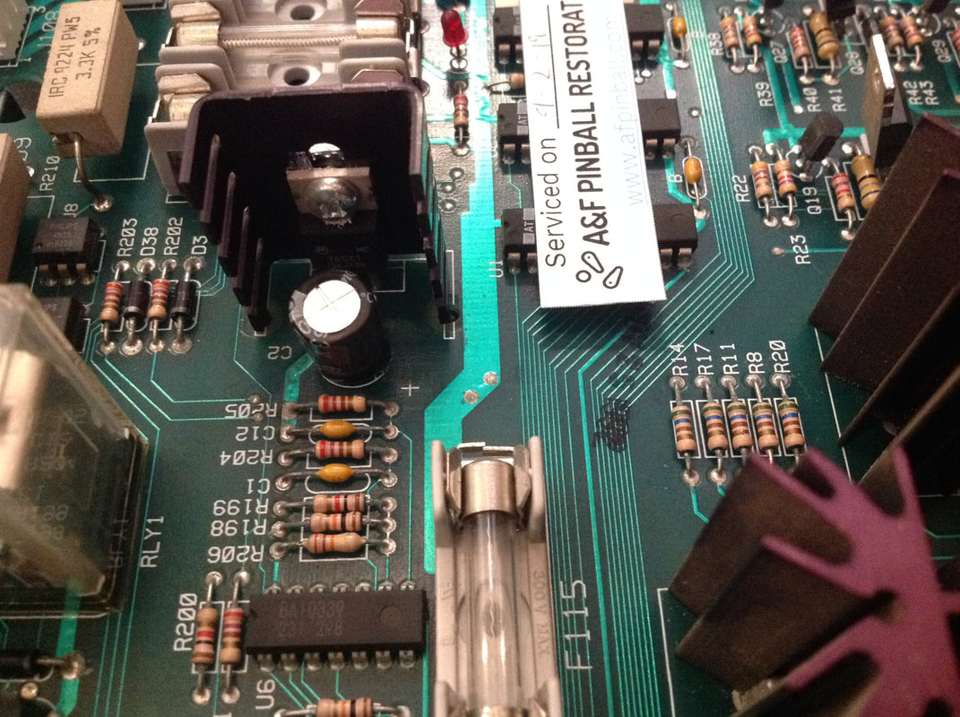
New C2 capacitor in place on the board.
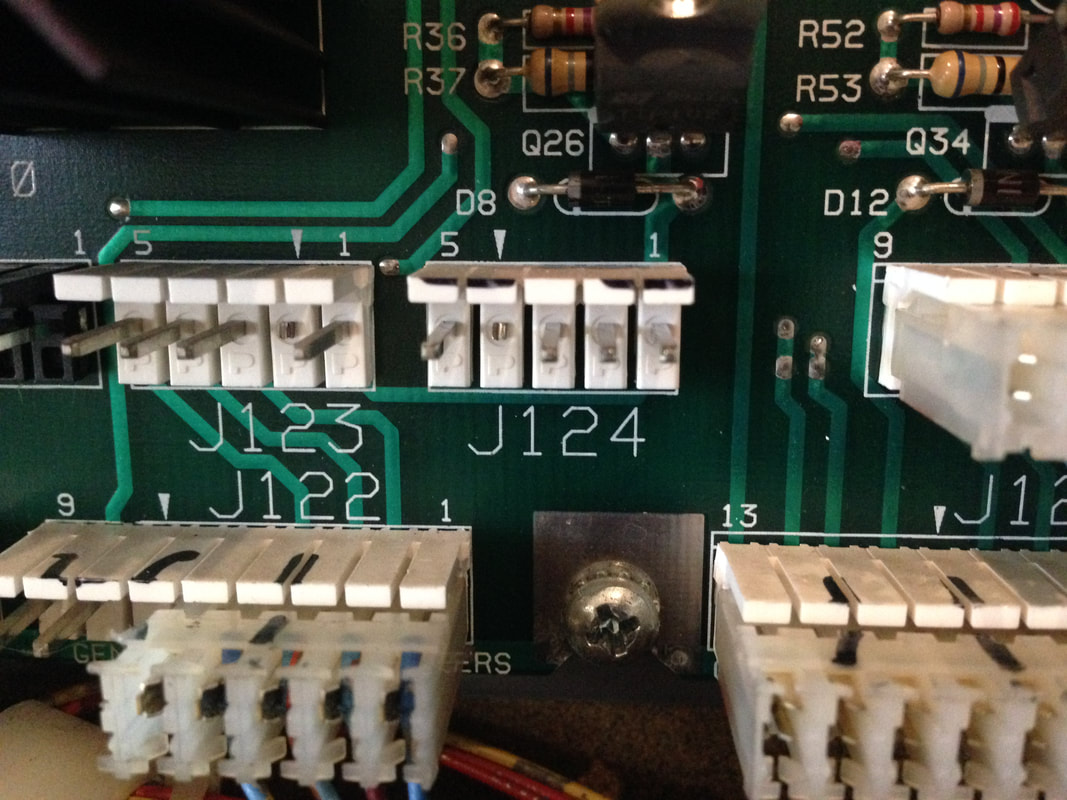
Backbox flashers locking on
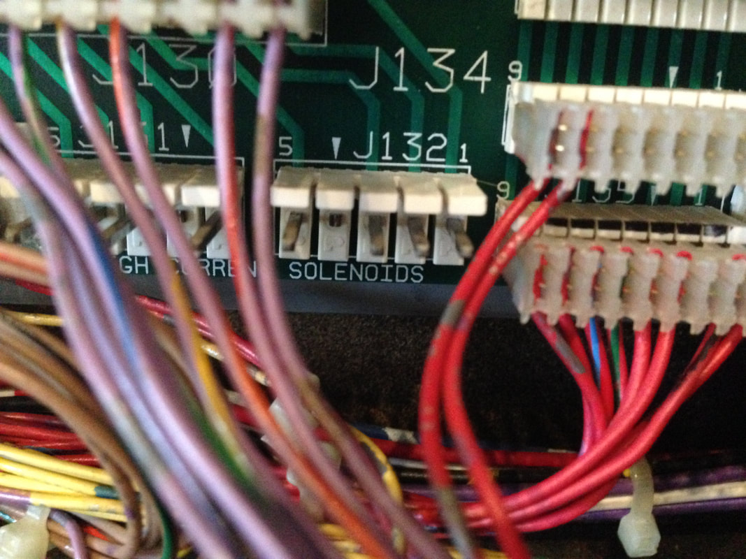
A great example of a simple problem which should never really be a problem! After repairing the power driver board and reinstalling it into the game, I found that some of the backbox flashers would lock on and stay lit as long as the game had power. This was caused by an error in reassembly. The connector that plugs into J124 (solenoid drive for the insert flashers) is keyed identically to the header pins at J132 (normally not connected to anything, but used to drive high current solenoids). By mistakenly connecting connector J124 to J132, I was driving the insert flashers with high voltage normally relegated to coils! Since voltage is always present at coils in WPC games, the flashers would lock on. Pinwiki details this problem specifically as it relates to World Cup Soccer (Bally, 1994), but the result is similar (locked on lamps and coils). Coincidentall,y J128 is also keyed in the same fashion. So, the lesson here is to be careful when reassembling the circuit board connectors, and to double check the connections with those listed in the manual! No flash lamps were injured in the making of this repair log.
Row of switches not working
This started out as a seemingly innocent issue which turned into a more major repair. I had noticed that a couple of playfield switches were not working. First, I noticed the centre jet bumper. Then, the left boat exit ramp. After putting the game into switch edge test and activating all of the switches, I realised that switch row 2 was unresponsive to any switch activations. The playfield wiring all seemed OK, so into the backbox I went.
I checked the connectors on the MPU board were correctly plugged in, and reseated them to be sure. No change. While inspecting the board, I noticed some telltale signs of the board having been corroded by battery alkali in the past. It had socketed chips at U19 and U20, and a new-looking battery holder. The proof was a little further down the board, however, in the resistor bank below U19. Two of these resistors were covered in green alkali fluid, which had eaten into the resistor legs. So, while most of the battery damage appeared to have been cleaned up, these resistors were missed. Or maybe these resistors showed no sign of damage when the board was first repaired, and the damage got worse over time. Who knows.
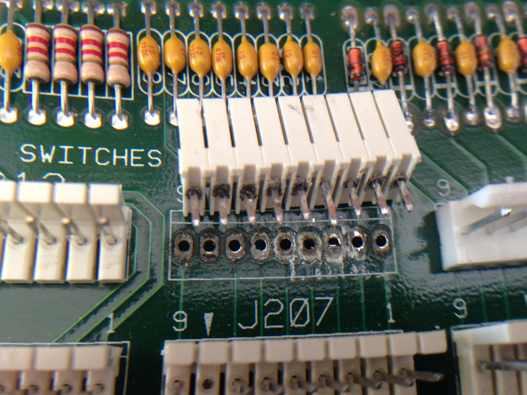
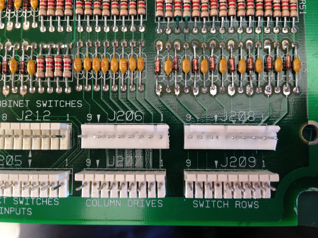
I replaced the resistors, but I didn't expect the resistors to make any difference to my issue. Spoiler: they didn't! But now I knew that this board had been damaged previously, I had a better idea of what to look for. I traced the switch circuit from the legs of U20 (column drive) to the connectors at J206 and J207, then from the legs of U19 and U18 (switch rows) to the connectors at J208 and J209. There appeared to be a break in continuity from J209 to the diodes and capacitors below U18. It looked like the break was at J208. Looking at the header pins, I saw what the origin of the problem was - corrosive alkali fluid! 
Light green residues on the header pins indicative of battery alkali.
So, I turned on the desoldering gun and moved along the backside of the connector, removing the solder from the header pins. The header wouldn't come out particularly easily, so I needed some pliers to unstick it from the board. Once it was off, the source of the problem was more clear. Battery alkali had seeped onto the pins and behind the header housing, disrupting continuity around them. I used vinegar to neutralise the alkali and then alcohol to clean everything up, but unfortunately continuity wasn't restored. I ended up running a jumper wire from the header pin to the next component in the circuit (one of the diodes above the header). Knowing that J208 had been compromised, I assumed that J206 would be compromised as well. After removing the header pins, the same corrosion damage was visible around the through holes. So, I used the same procedure to clean the traces around J206. Luckily, there was no impact on circuit continuity for the column drives. It was time to install new headers at J206 and J208. These are available locally (RTBB, PSPA). Depending on what is available, you may need to cut down a larger header strip, as I did. Once the new headers were installed and all the board traces checked out OK, the board was reinstalled in the game and tested. The previously unresponsive switches on row 2 now worked!
I didn't want the customer to ever have to deal with battery corrosion issues again, so it was time to remove the battery holder from the MPU board and install a remote battery holder. Simple, 3x AA battery holders are readily available online (eBay) and can be installed easily, so I perform this mod on most games I own and service. Simply clip the old battery holder from the board, melt the solder and remove the remaining legs from the through holes, and hook up the battery holder to the positive and negative terminals on the board. Then, simply sit the battery holder in the backbox, or affix it to the backbox wall for a cleaner install.
Drop target assembly issues
This was a similar problem to one that I tackled on my own Fish Tales. The drop target assembly uses an actuator arm to poke the drop target backwards when it is in the up position. This makes the target fall down. This is important on Fish Tales because it allows the game to clear the path to the lock shot. With the target unable to drop itself, the lock shot requires two shots to make - one to drop the target, and one to land in the lock.
This assembly had a couple of issues. First, the ball popper cap (part no. 03-8053) was missing from the plunger. This part is readily available (RTBB). A new one was ordered and was inserted over the plunger and secured in place with a roll pin. 
New ball popper cap installed.
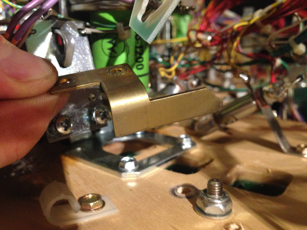
However, the lack of a cap was not the reason that the drop target could not lower. The actuator arm (part no. 01-8647-R) had broken, such that the "arm" was no longer present. This part simply needed to be replaced (PSPA). Once it was replaced, all was well again.
Reel assembly drive belt missing
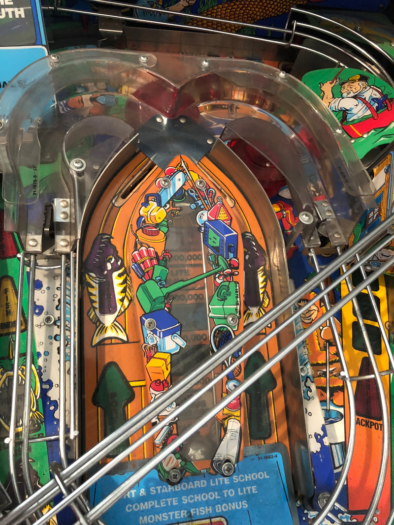
The reel lock mechanism uses a special drive belt to connect the motor gearbox to the reel above the playfield (part no. 03-8614). This game was missing a drive belt altogether, therefore the game could never keep track of how many balls were locked and would often spit them out of the lock instead of retaining them. Luckily, I had a spare drive belt from when I had to replace it on another Fish Tales machine. It is also available locally (RTBB, PSPA). The reel needs to be disassembled to the point that you can remove the motor and gearbox assembly from beneath the playfield. Then, the new belt can be pulled over the pulleys. A new belt will be quite tight so it requires a fair bit of force to get the belt on. It should be tight, as the belt should not slip while carrying the weight of the balls in the lock. This is why a regular rubber ring will not work. Trough wire gate missing
This wire gate (part no. 12-6542) is often broken (or missing completely) as balls getting sent into the trough will hit it with a lot of force, and it then swings upwards and hits the underside of the apron. So much physical impact eventually breaks the wire. It is readily available (PSPA, RTBB) and easy to replace. I always keep a few of these spare as I am always replacing them.
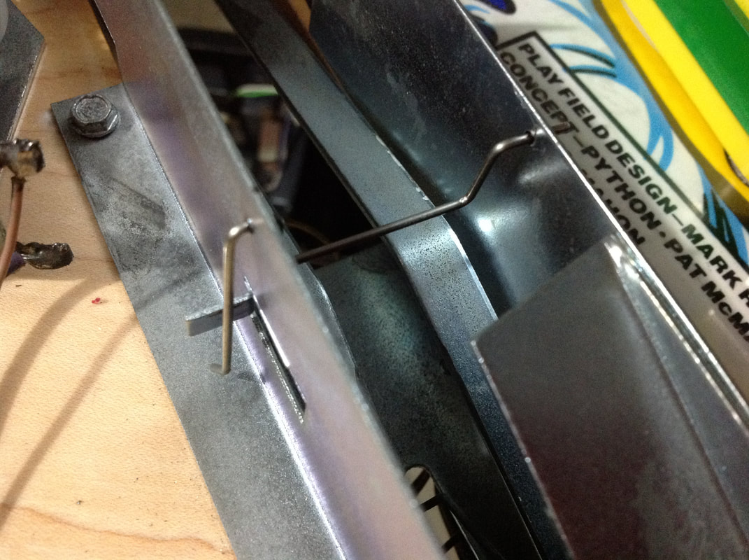
New wire gate installed in the ball trough.
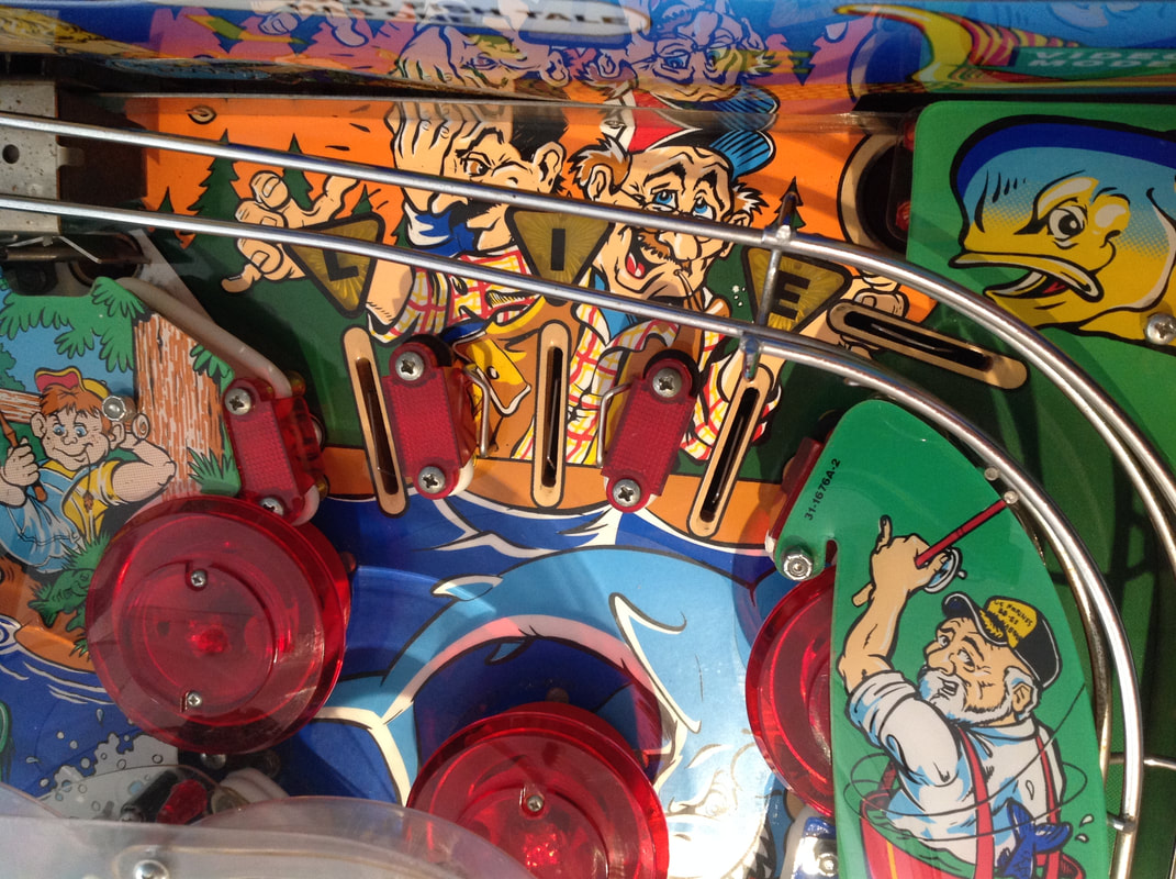
Right pop bumper wafer cracked and lamp not working
Unfortunately there are no pictures of these parts, but the problems were fairly self-explanatory.
The pop bumper wafer (part no. 03-6035-4) on the right pop bumper had cracked from repeated ball impacts. This was probably what had caused the excessive dirtiness and wear around the pop bumper. Ideally, the pop bumper wafers should be round so that balls will activate the bumper at all points around their circumference. The general illumination lamp inside this pop bumper's body was also broken due to a severed lamp socket lead. So, the whole pop bumper assembly had to come apart. There was no need to install a new wafer in this case, as the right side of the pop bumper is under playfield plastics and never gets seen by the ball, so the wafer can simply be rotated so that the intact side now faces the ball action. Easy! As for the lamp socket (part no. 24-8776), I have replacement lamp sockets with wire leads just for this purpose. These are available from RTBB and PSPA. The metal leads are a pain to bend, feed through the playfield, and then solder. So I replace these with wire lead sockets, which are much easier to manoeuvre and solder. With the new socket in, the lamp was working properly again. While the bumper was in pieces, there was a good opportunity to clean away the grime that had collected on the playfield as a result of the broken wafer. After a quick clean with Novus 2, the area was shiny again.
Left inlane switch not activating reliably
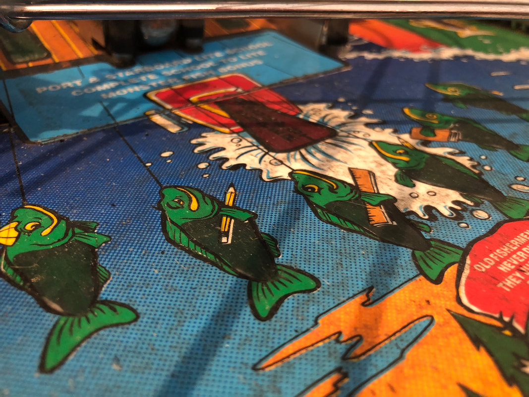
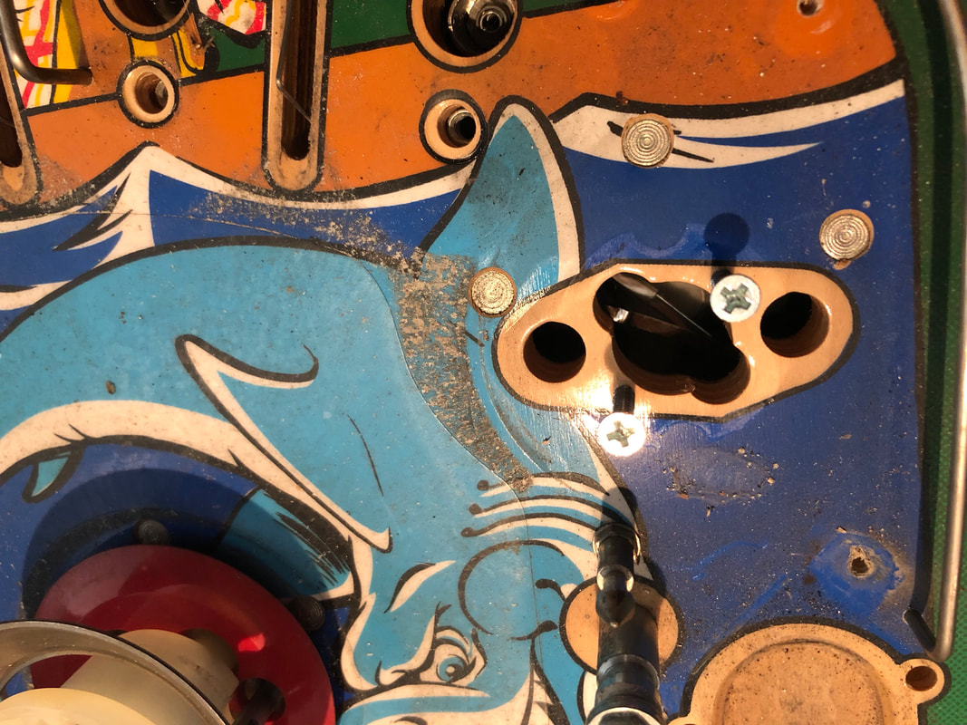
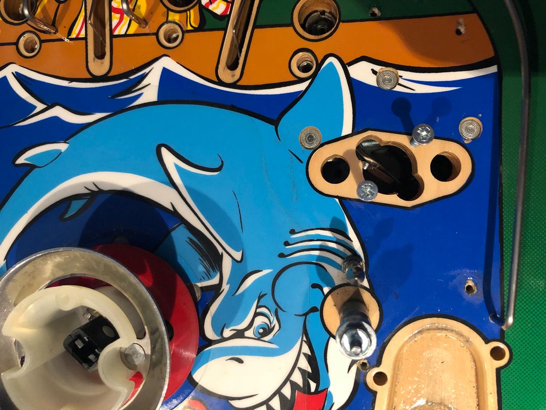
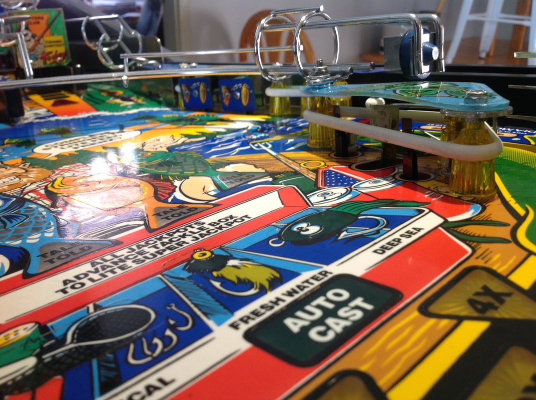
I noticed during playtesting that the left inlane switch was not activating properly. It would work intermittently, and when testing the switch using a ball in test mode, it would only work about half of the time. After removing the microswitch (part no. 5647-12693-19) and inspecting it, I found that it was sticky, and would often not return to its home position after actuation. Once a switch gets to this point, the internal components are likely worn, and replacing the switch is the only way to restore full functionality. I had a spare that I was able to place in the game after relocating the wire actuator from the old switch onto the new switch body. It's handy to have a bunch of switch bodies rather than complete switch and actuator assemblies, as you can usually transfer the old actuator. This particular type of microswitch is commonly used for playfield rollover switches in WPC games (available from PSPA as a full assembly with actuator and from RTBB as a bare switch). Plastic post at top rollover lanes loose
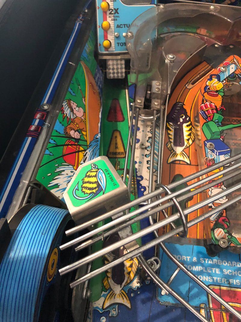
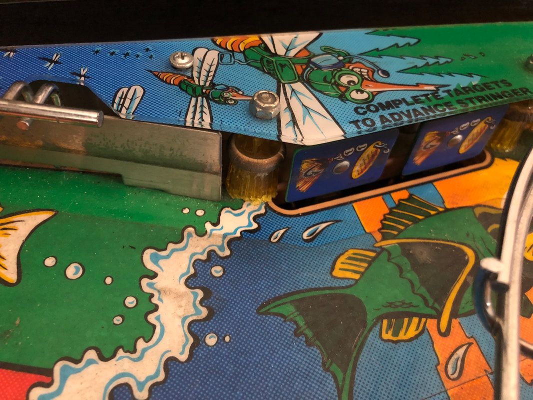
This is possibly an issue of poor game design, but this is the first time it has caused an issue so it may be due to slight variations between games. The leftmost plastic post (part no. 03-8365-16) is positioned so close to the pop bumper that it basically sits underneath the pop bumper cap. This is not a problem per se, but on this machine, the post was close enough that the rod and ring assembly on the pop bumper would strike the rubber ring on the post, jolting it around. Over time, this put stress on the T-nut holding the post under the playfield, to the point that the T-nut fell out of the playfield.
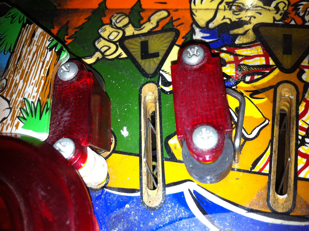
Plastic post (at left) positioned under pop bumper cap.
This was fixed by installing a new T-nut and moving it upwards ever so slightly to move it further away from the pop bumper. This seemed to help as the rod and ring can move up and down without impacting the rubber ring on the post. However, this may need to be checked in the future to ensure that the post does not get struck. There is not much else that can be done without physically moving the playfield mounting holes for the pop bumper or the plastic post, but this simple realignment, as well as using a slightly smaller rubber ring on the post, worked well. Reassembly As I have worked on Fish Tales a few times already, playfield reassembly came together quickly after cleaning. All of the coil mechanisms under the playfield got a clean and service, too, and play was nice and snappy after that. The customer wanted LEDs to be installed in his game and it looked great after removal of the incandescent globes and installation of the LEDs. I went for white LEDs throughout the game this time, as this gave a more consistent colour temperature throughout the game. All of the inserts looked great, including the yellow and orange ones, which are usually a bit dim with yellow and orange coloured LEDs (for some reason these colours of LEDs are less bright). The backbox topper, in particular, always stands out nicely with flexible lead LEDs pointed up at it. The machine had new white rubber rings installed throughout. The flippers were fitted with green Super-Bands, so the customer won't have to worry about the flipper rubbers wearing out too quickly (he's too far away for a service call!). New flipper parts were also installed to make sure the flippers would be nice and strong for a long time to come. I installed a set of the same great instructions cards I use on my own machine, created by Pinside user Soulrider911. I still really like these cards as they complement the colours on the playfield really well.  Conclusion When all was said and done, about 20 hours went into refurbishing this machine. Some of these hours were spent troubleshooting boards and cleaning the playfield, as described in this post, but I spent a number of hours sourcing parts, performing small upgrades, and making sure the circuit boards were in good order for the future. The customer was very happy with the final result and was amazed at how bright the LEDs made the playfield look. As the game had not been in a playable state for several years, he was keen to get it set up at home. It had a couple of birthday parties coming up which it would need to perform for, and with all the work I had done to it, it should perform well for years to come!
5 Comments
Mike Lewis
30/9/2019 09:52:19 pm
Hi Alex - really enjoy your pinball restoration blog. I see you've done many Fish Tales. I'm attempting a Fish Tales restoration here in the UK. Just wondered if you could share any information on the tilt mechanism on this machine as mine has been ripped out.
Hi Mike
Mike Lewis
12/10/2019 09:03:33 pm
Thanks Alex - that's very helpful.
Hi Mike Leave a Reply. |
About
Here you will find logs of our pinball and arcade machine restorations, repairs, discussion about general pinball and arcade topics, as well as recounts of our random pinball adventures.
Check back regularly for updates! Blog updates
Archives
May 2024
Categories
All
Donate

Running this website is a hobby for me (just like pinball!). I like being able to show off my restoration work so everyone can learn from it and potentially fix their own machines. If you enjoy reading the site's content or it has been helpful to you, please consider donating to offset some of the website's operating costs. |


 RSS Feed