|
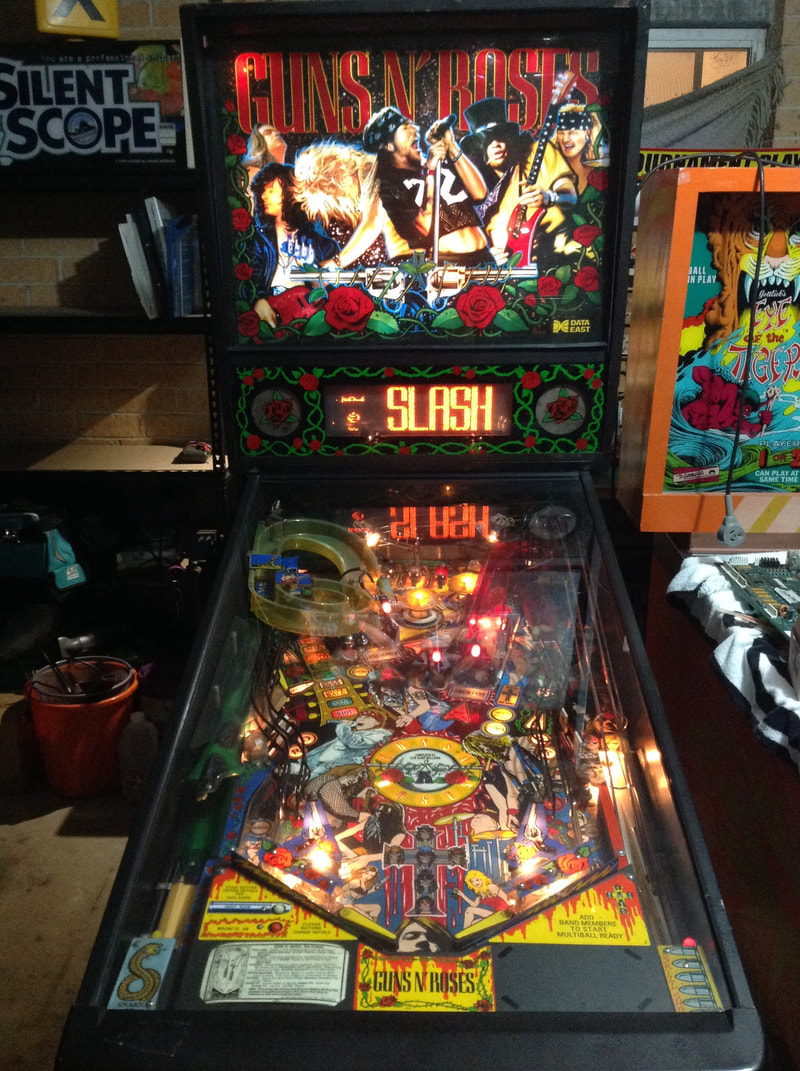
Many people consider Guns N' Roses (Data East, 1994) to be one of Data East's best pinball machines. One of the few rock music machines from the 1990s, it is a really cool game with some interesting design decisions incorporated into it. While a lot of people prefer the more modern music themed games such as AC/DC or Aerosmith or Metallica, I still prefer the older games, so Guns N' Roses scratches that rock theme itch perfectly. This will be a shorter blog post as this was not a full restoration by any stretch. There was limited disassembly performed and pictures were only taken of the issues I was tasked with fixing. My customer had pulled the machine out of his warehouse for the first time in years and wanted it to brought back to working condition. No cosmetic fixes and no fancy stuff. I just needed to get it back up and playing. So, I won't bother with the standard descriptions of the machine's condition or nitpick the defects. However, I performed some interesting repairs on this machine which warranted writing some of them up. So, let's jump right into the repairs! Tips & Troubleshooting (click on sections below to view details) Right drop targets stuck in raised position
This was one of two original problems that the customer wanted fixed to start with. The three drop targets on the right of the playfield could not be knocked down. It became obvious that this was because the reset coil was locked on, and keeping the targets pushed up. Opening the door cut the high voltages to the coils, and allowed the drop targets to fall normally. However, closing the door and re-energising the coils locked them in the up position again. There was nothing wrong with the coil itself as the coil was the correct type, measured the correct resistance, and was wired correctly.
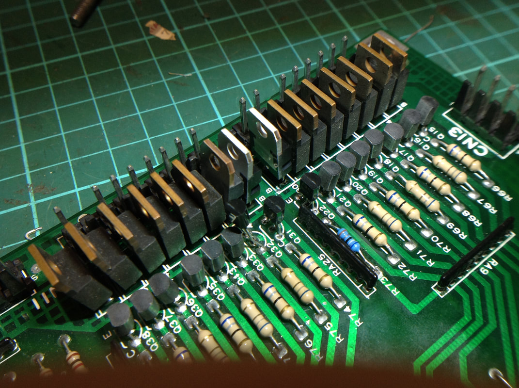
So, let's move on to the backbox. The customer advised that he had replaced the driving transistor already, as well as the associated resistor. The primary driving transistors are TIP122s and the right drop targets are driven by Q30 on the CPU board. This transistor had been replaced with a TIP102 (RS Components, RTBB, PSPA, Mr Pinball), which is the recommended replacement, but you can also use another TIP122 if you wish (RS Components, Jaycar, RTBB). Testing it using diode test on my meter gave suspect results which were "off" when compared to the other transistors nearby. Just to be safe, I replaced it with another TIP102. Still, the coil stayed locked on. The new transistor tested OK, so I started to suspect prior repairs to the board. The transistors are driven by two 7406 integrated circuits (Jaycar, RTBB) located at 2J and 1J just above the driving transistors. In particular, Q30 is driven by 2J, the output of which is at pin 3. Using my logic probe, I could see that the output was pulsing properly whenever the coil was activated in test mode. Even after swapping the chips at 1J and 2J (luckily whoever replaced them previously had socketed them), there was no change. So, it looked like all of the circuitry above the driving transistors was working properly. The problem had to be downstream. After verifying the connectors and wiring were all intact, I looked again at the driving transistors. Everything had been replaced in this section except for the predriver transistor at Q23. I took a closer look at the transistor and discovered what the problem was. This is supposed to be a 2N4401 transistor (NPN type). However, what was installed was a 2N4403 (PNP type). Some idiot had replaced this transistor with the wrong type! The outputs of NPN and PNP type transistors are basically reversed, so the coil was being driven high constantly instead of being low constantly. I replaced it with a PN100 transistor (Jaycar). I love the PN100 transistors as you can keep a bunch of them in your toolbox and they replace a number of other NPN transistor types. But, if you're a stickler for originality, you can also order replacement 2N4401s, too (RS Components, RTBB, PSPA, Mr Pinball). And that turned out to be it. The drop targets worked normally after that. The lesson to learn here is twofold: always replace the predriver transistor after replacing a larger transistor, and always inspect the components installed during previous repairs to see if they're the correct type. Magnets not working
I know I said this wouldn't be a very long blog post, but that was before I decided to include all of the details on troubleshooting the magnets. Prepare for another repair saga.
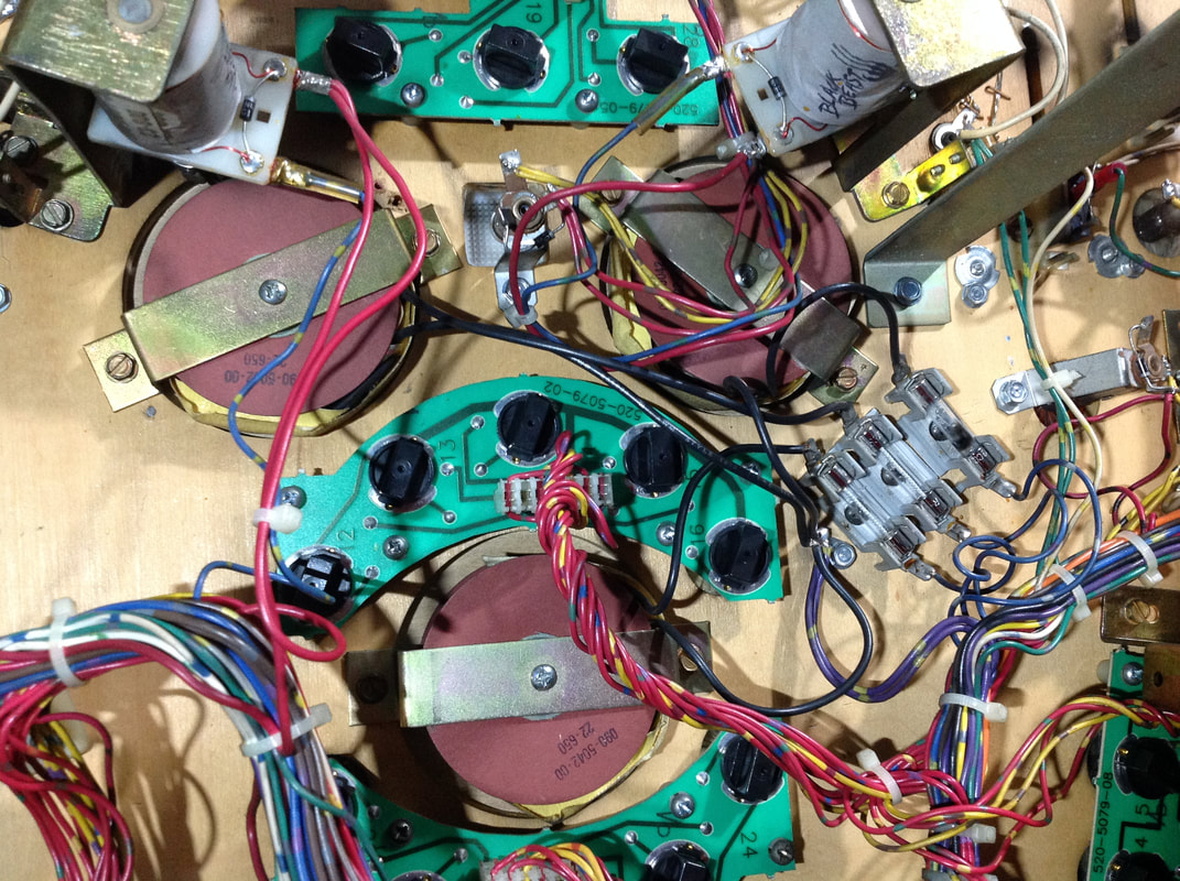
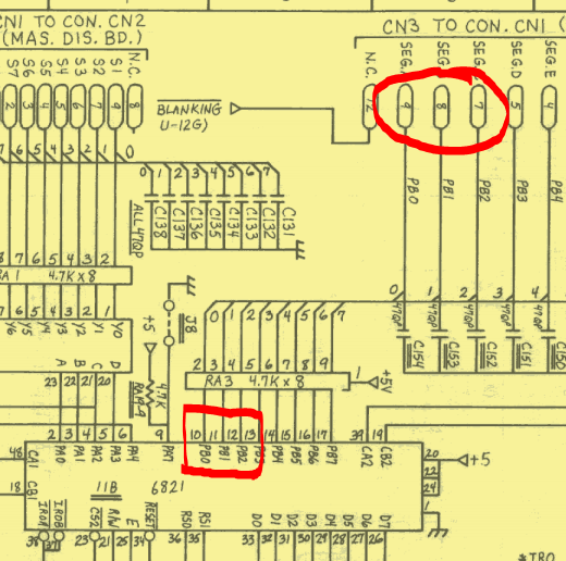
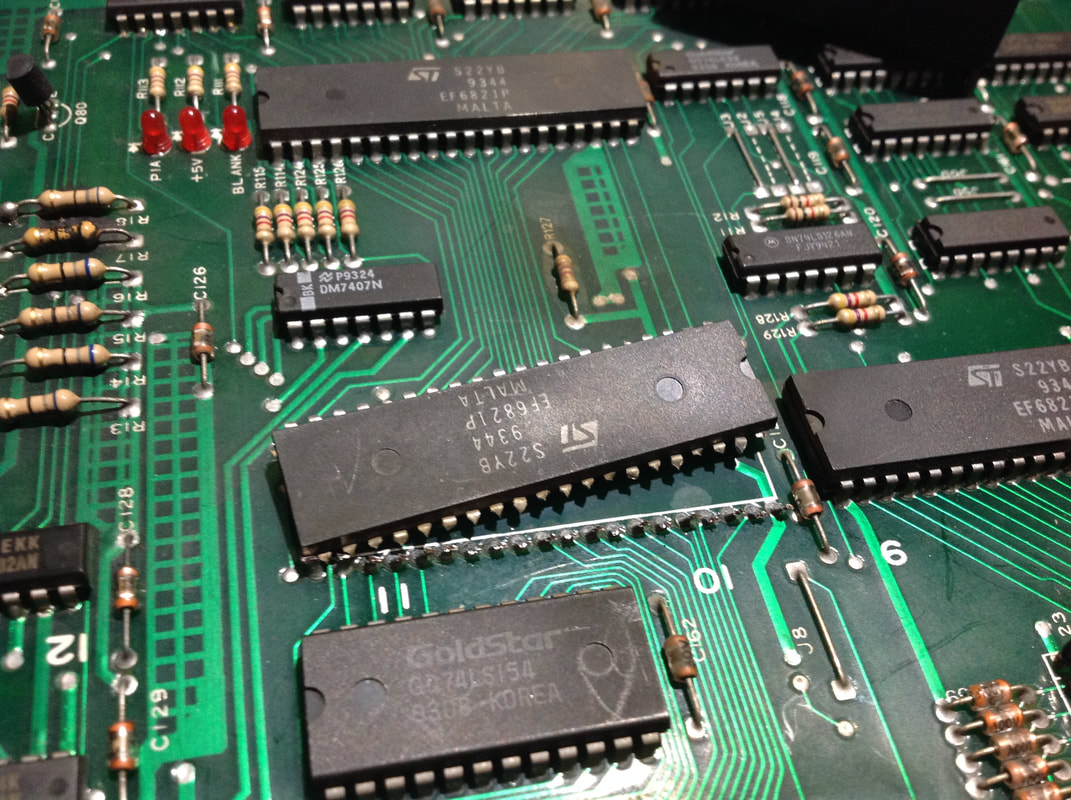
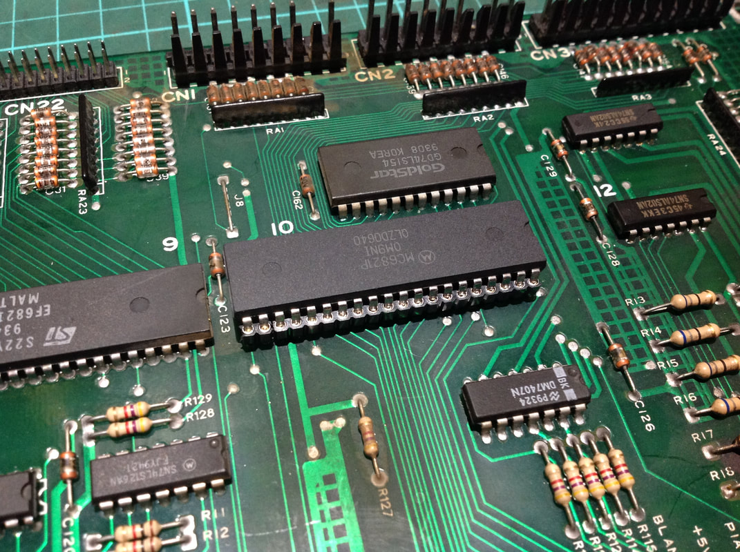
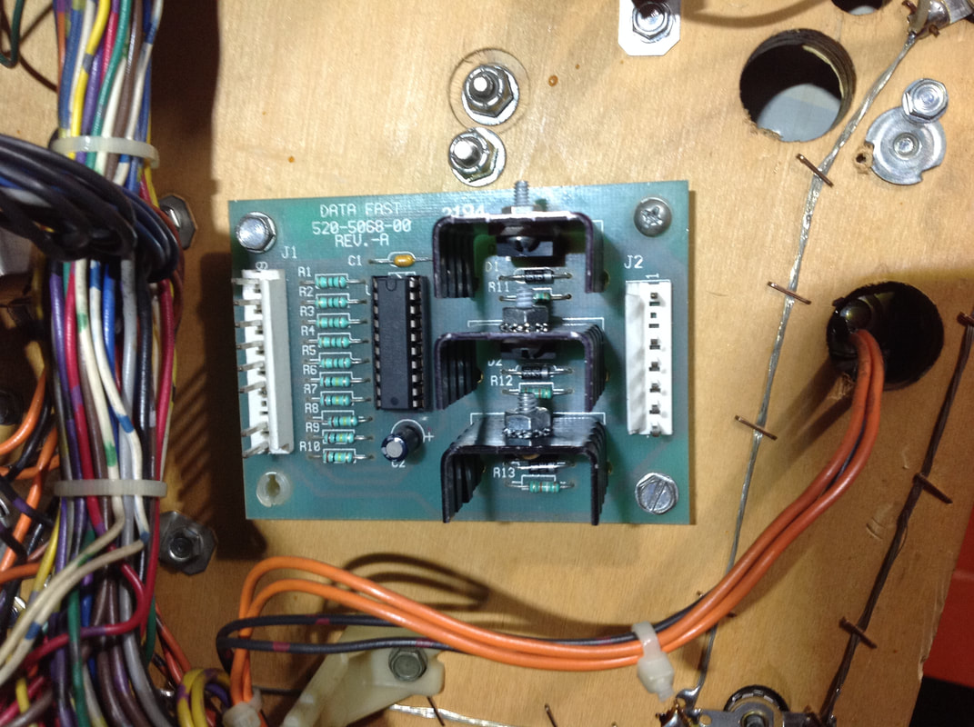
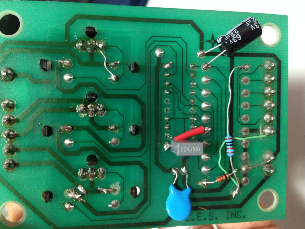
One of the customer's main complaints about the machine was that the magnets did not work. I was well accustomed to the Data East three playfield magnet setup due to the work I did previously on Last Action Hero (Data East, 1993). Guns N' Roses uses the exact same setup, with three magnets, fused by three fuses, and driven by a magnet board mounted to the playfield, which is connected to the MPU. The troubleshooting involved the following sequence of events. First, I checked what the magnets were actually doing when they were supposed to be on. As it turns out, nothing! No magnet activity at all. Looking under the playfield, I saw why - two fuses for the magnets were missing entirely, and the last one was blown. No problem! I put three new fuses into the game, and tried testing the magnets again. This time, I had a feeling the magnets may lock on, so I made sure I was able to open the coin door quickly to cut the voltages to the coils in case this happened. When the game turned on, I heard the tell-tale buzzing sound indicating that the magnets had indeed locked on, and the ball I had balanced on the playfield was sucked immediately towards one of the magnet cores as soon as I flipped the power switch. I then turned my attention to the magnet driver board. Testing the MOSFETs on the board, I could see that they were all shorted internally. This was causing the magnets to lock on. Gingerly, I replaced the MOSFETs with new IRL540 MOSFETs (RS Components, PSPA). When I plugged the board back into the game, the magnets locked on again straight away. When I rechecked the magnet board, I saw that the new MOSFETs had also shorted internally, and I was back at square one. Now, this is the stage I reached when working on Last Action Hero. With Last Action Hero, I tried replacing the MOSFETs and doing a bunch of other tests until I went mad. Eventually, I just replaced the magnet board entirely with a new Homepin replacement board (Pinball Haus, PSPA). That fixed the issue on Last Action Hero, so it was good to go. I decided to do the same thing with Guns N' Roses as I was at a standstill, so I bought a new board and installed it, fully expecting it to solve all of my problems. And, it didn't. Was the brand new Homepin board dead on arrival? I wasn't so sure. As a test, I took out the MPU board and put in my spare MPU. After the magnet board, the next step up in the chain is the MPU board. If the problem wasn't with the magnet board, it would be with the MPU, right? Right! When I turned the game on with my spare MPU board, the magnets did not lock on. Progress! They worked perfectly in test and in gameplay. Awesome! So, what did this mean? It meant that the problem with the magnets was not only the shorted transistors on the magnet board but it was also an issue with the original MPU board, which was not turning on the magnets when it should. But why was this happening? Back in my Last Action Hero restoration, I did a little bit of digging in an attempt to find out what drives the magnets on the CPU board. Schematics for the magnet driver board were provided with a July 1994 Manual Amendment, indicating that inputs 1, 2 and 3 for the magnets are provided by CN3 on the MPU (pins 7, 8 and 9). Looking at the CPU board schematic, one can see that these pins are connected to the PIA at 11B, via the resistor array at RA3. The resistor array tested fine, so my suspicions were directed towards the PIA. Perhaps it wasn't sending the correct input signals to the magnet driver board? To test this, I used Leon Borre's excellent Data East test ROM. As I didn't have a spare 27512 EPROM, I used the game ROM instead (also a 27512). I simply removed the game ROM, erased it, and burned the test ROM image onto it. When I was done testing, it was easy to erase the ROM again, and copy the latest version of the Guns N' Roses ROM (v 3.0) back onto it. This is a bit of a fiddly process just to test a ROM, but necessary if you don't have the right ROM chip handy! As described on the Pinwiki page, Leon's ROM simply pulses each of the outputs on all of the PIAs so you can see if they are working or not. Each output will oscillate from 0 to 5 volts which can be seen with a multimeter or logic probe. Pins 2-17 on most PIAs will operate in this fashion. As I tested along the line, each of the outputs seemed to be working. That was until I got to pins 10, 11, 12 and 13. None of these pins showed any activity and were stuck low (0v). These pins are associated with Peripheral Interface B in the chip. Looking at the schematic I could see that pins 10, 11 and 12 were connected to CN3, and were the same pins that drove the inputs sent to the magnet driver board. Eureka! This was probably where the problem was. So, the next step was to remove the 40-pin PIA and install a new one. I hate removing PIAs and processors as they are always large chips. Larger chips mean more opportunities to destroy a via or mess up a trace. Thankfully, all of the traces remained intact and it only took 30 minutes or so to complete. I reinstalled the board, started a game, and triggered multiball to test the magnets. Success! All three magnets worked as they should. But this was not the end of the repair. At this stage, I was still using the Homepin magnet driver board. Now that the MPU board was in working condition, I wanted to see if I could finish the original task I had failed with Last Action Hero - repairing the original magnet board. Now that I had a working and upgraded Homepin magnet board, I decided to upgrade my original magnet board with the modifications implemented on the Homepin board to bring it back to life. These mods include:
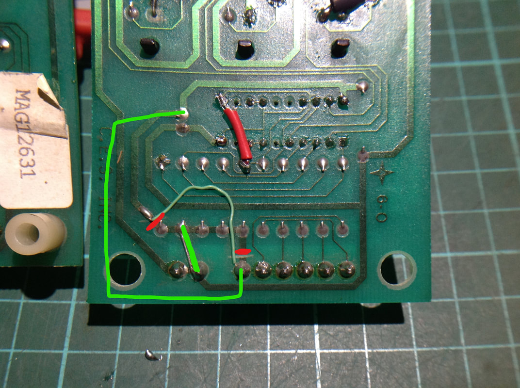
And that's it for additional parts. The connection points above are the ones I used, but the additional components can be connected in multiple ways and still work, as long as continuity to the components listed above is maintained. A few other notes about modifications to these boards. On original magnet boards, the jumper wire from J1-4 to C2 appears to be a modification done at the factory after an error in board printing which erroneously connected J1-4 to R6, R7, R8, R9 and R10. I have seen another magnet board where somebody removed this jumper wire, rendering the board inoperable. Not only should the jumper wire be installed, but the factory trace from the positive leg of C2 should be severed so it does not connect to any of the resistors. As well as the jumper wire above, another should be installed to connect J1-2 to R6, R7, R8, R9 or R10. All of these resistors are connected via a single trace, so the jumper need only connect to one of them. The original error at the factory, it appears, was mixing up J1-2 and J1-4 and connecting them to the wrong components. The image below shows how the traces should be made and cut. So, did it work after all of these modifications? Yes! The solder side of the board turned out to be a bit of a mess of jumper wires and new components, but it worked just as well as the Homepin board, so I'm happy! I could finally put this magnet board saga to rest. It only took me two machine repairs to figure it out, but I got there in the end! Knocker and flashers not working
When I first took a look into the cabinet, I realised that the knocker wasn't working before I turned the game on. That was because somebody had disconnected the wires to the knocker. Simple fix, right?
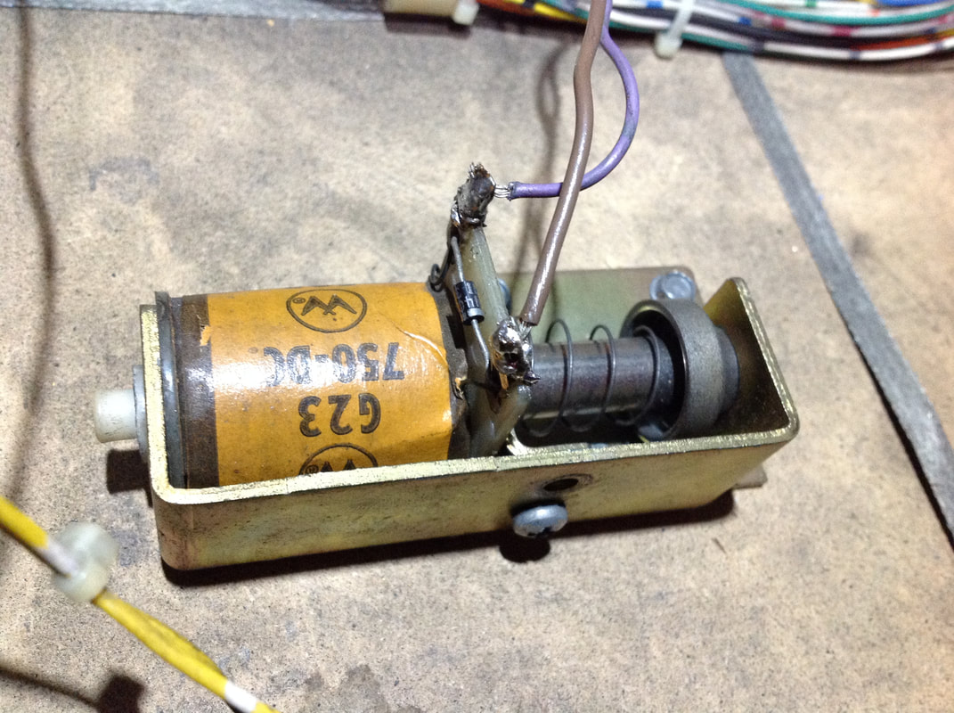
I wired the knocker back up, making sure the wires were positioned correctly. According to the solenoid table, the power wire is brown and the control line connecting to the transistor is purple. Make sure you wire the power wire to the banded side of the diode. The knocker coil in this game was a Williams coil, a G23 750-DC, to be exact. The fact that it was a Williams instead of a Data East coil is no big deal. At some point, an operator without the correct replacement coil probably whacked this one in instead. However, there is one thing you need to check when a different coil is being used in a particular application. Check that the gauge of wire and number of windings in the coil is similar to the one that should be there. Also check that the resistance across the coil lugs is also similar to the correct coil. This will ensure that the coil can still be turned on by that circuit without stressing the driving componentry. A great resource for this is the Flippers.com coil resistance chart. This coil had a resistance of about 3.7 ohms, with 23 gauge wire at 750 turns. The correct coil is supposed to be 4.5 ohms, with 23 gauge wire at 800 turns (part no. 090-5001-01, RTBB, PSPA). So, not an exact replacement. In fact, this coil will be a little stronger. But the figures are close enough that it will work. However, it didn't work. That's not because the coil was incorrect, or the wiring was bad. Those were both fine. But the coil was not firing at all in test mode or in the game. While troubleshooting the issue, I also discovered that the flashers under the G ramp were also not working. Now, Data East used a relay on the playfield power board to switch power from the coils to the flashers. Coils are driven by the L side of the relay, while flashers are driven by the R side. On Guns N' Roses, eight sets of coils and flashers are multiplexed in this way, with each "position" of the relay responsible for activating one coil and one set of flashers. The knocker was designated coil 8L and the flashers under the G ramp were 8R. So, they were both driven by the same transistor on the MPU board. This was Q39. After I checked that the wiring and connectors were all OK, I focused on the transistors. I was suspicious that the knocker may have been wired up incorrectly at some point in the past, which is why I found it disconnected to start with. Doing this is guaranteed to damage the driving transistors, as they no longer have a correctly oriented diode on the coil to protect them from the voltage spike from the coil's magnetic field collapse. So, without further ado, I just replaced the transistor at Q39 with a TIP102 (RS Components, RTBB, PSPA, Mr Pinball), and the predriver at Q31 with a PN100 (Jaycar). You can replace these with the original TIP122 and 2N4401 transistors, respectively, but they are not as robust. See the section above dealing with right drop target faults for links to purchase the original parts. Once the new transistors were in, the coil and flashers both worked as intended. There was no further damage to the logic components further up the chain than the transistors, which was lucky. Sometimes, badly wired coils can wreak havoc on the integrated circuits driving the transistors, as well. In that case, repair would be a lot more involved and time consuming. Balls getting stuck in shooter lane
Guns N' Roses might be a fun game to play but there was one part of the game which was poorly engineered and severely undertested (if it was tested at all). That area is the shooter lane ramp. This part of the game has so many problems that Data East released not just one, but two separate service bulletins (SB 63 and SB 64) to describe how to fix its issues.
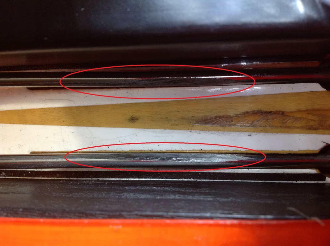
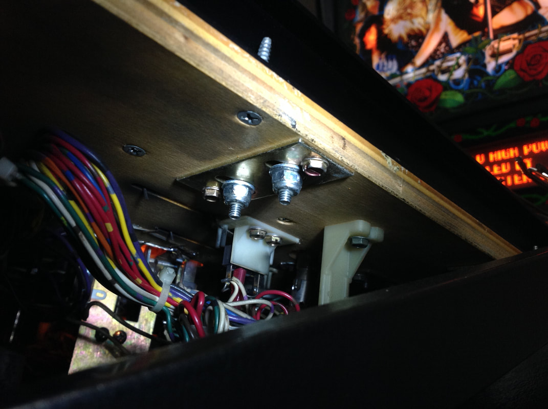
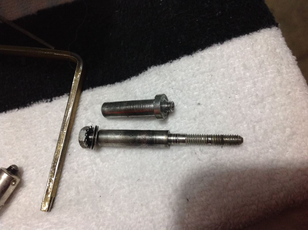
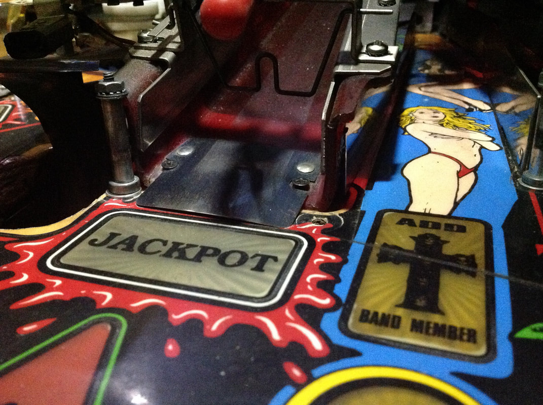
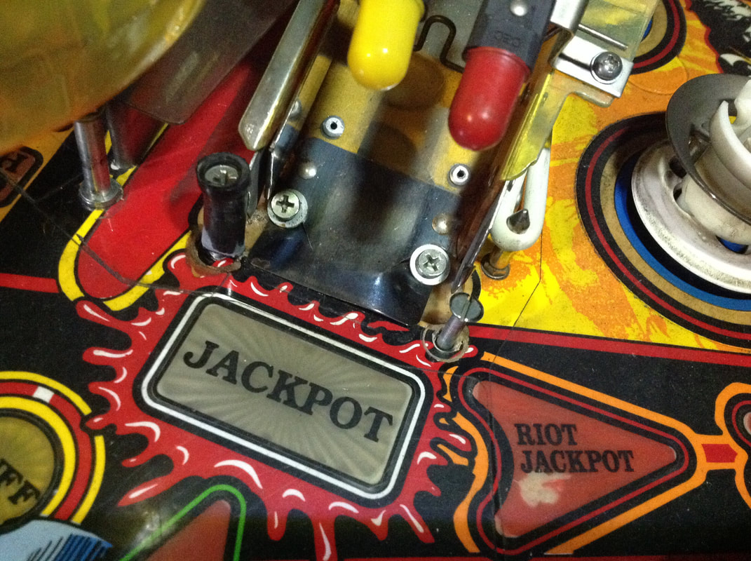
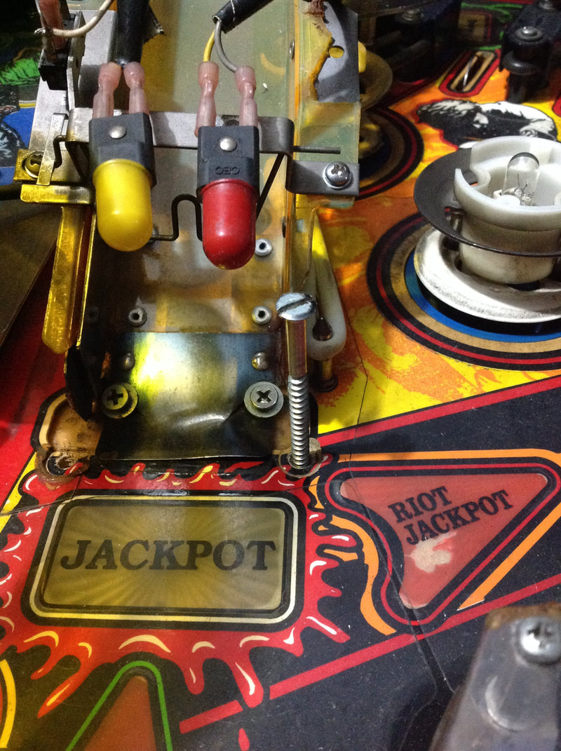
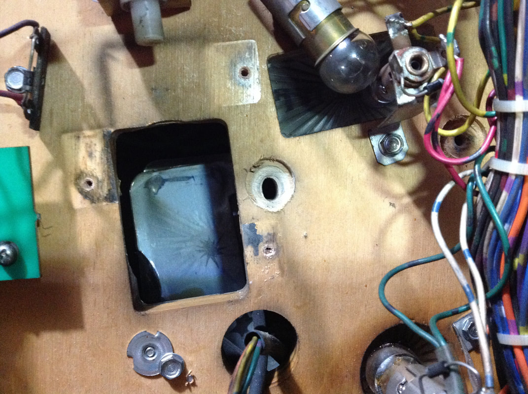
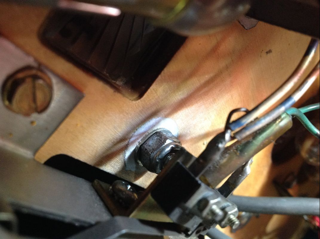
The crux of the issue is that the shooter lane ramp is much too steep. Occasionally, balls will not make it all the way up the ramp, and will fall back down to the shooter lane. During normal gameplay with a single ball, the coil will simply keep trying to fire the ball until it finally makes it all the way up the ramp. Sometimes, it never makes it, and eventually the coil burns up, fuse F5 on the playfield power board blows, or something else in the mechanism fails. The problem is even worse in multiball, because the game software doesn't recognise that a ball has failed to make it up the ramp. So if it needs to serve another ball into the shooter lane, it will, even if another ball is there from the last failed launch. The coil will then try to launch two balls into play, which will obviously fail. Then the process repeats again as the game serves a third ball into the shooter lane. The game will continuously cycle the ball shooter coil until it destroys itself or blows a fuse. The way to solve these issues according to the first service bulletin is to adjust the leg levelers so they are as far in as possible, reducing the playfield pitch, and ensure that the ball shooter coil and associated assembly are in good order with no loose parts. There is also another version of the shooter lane ramp which is coloured black. This ramp reportedly had a higher pitch than the standard chrome ramp and should not be used. Apparently, those measures were not sufficient, and the second service bulletin suggests changing the way the shooter lane ramp is mounted to the backboard at the top of the playfield. The mounting point can be moved slightly lower, to further reduce the pitch of the ramp. I was experiencing the typical issue of balls occasionally not making it all the way up the ramp. I installed a new coil sleeve in the ball shooter coil. The bracket holding the coil to the assembly was a little loose, so I tightened that as well. Finally, I loosened the three woodscrews holding the entire assembly to the playfield, and readjusted it so that the plunger would strike the ball dead on. I decided not to adjust the mounting position of the ramp as my issues turned out to be elsewhere and unrelated to the pitch of the ramp. This game already had a chrome shooter lane ramp instead of the steeper black ramp too, so there was nothing else to be done there. My problem was actually at the very start of the shooter lane ramp, and wasn't really related to the angle of it. Occasionally, balls would strike the entrance to the ramp wireform. The balls would therefore bounce around the wireform entrance, wouldn't make it into the ramp and would fall back into the shooter lane. After watching some footage of ball launches in slow motion, I realised that the balls were being flung left and right at the point that they first contacted the shooter lane ramp. When I inspected the ramp itself, I realised that the edges of the wireform were chamfered from wear. This was causing the balls to veer left and right as they tried to mount the wireform, sending them all over the place. It was a very similar issue to the one I had with Tales of the Arabian Nights (Williams 1996), which also sends balls onto a ramp at launch. Fixing the problem of Tales of the Arabian Nights was easier as the ramp is plastic and can simply be sanded down. This ramp is not as easy to mould. However, it can be adjusted. The ramp is bolted to playfield via two nuts that hold onto the wireform from the underside. These can be fastened tightly, which will pull the wireform into the playfield as much as possible. Or, they can be loosened, which will allow the wireform to sit slightly higher. As the issue here was one edge of the ramp being more worn, one of the nuts simply needed to be loosened to raise the other edge of the wireform a little higher to compensate for the wear. It required a bit of fine tuning, however, I found that loosening the right side of the wireform slightly while keeping the left side bolted firmly to the playfield allowed the balls to roll smoothly through the ramp entrance. From there, they had no problems with clearing the rest of the ramp. The real test for this fix was to run the game through starting multiball ten times, and ensuring that every ball cleared the ramp on the first try. They all did, so, success! So, while my problem wasn't really the same as those dealt with by the service bulletins, it was still a good exercise to go through all of those checks to make sure things were in good order. Looking back, it was a big exercise to check all of the details in the service bulletins and make the necessary adjustments. It really shows that Data East did not playtest this machine thoroughly enough before release. To release two service bulletins to fix the same issue is pretty bad. Multiball is a major part of Guns N' Roses, with several modes being multiball-based, and the main multiball using up to six balls. When the major parts of the game revolve around multiball, you better make sure the game can launch more than one ball onto the playfield consistently. Pop bumper issues
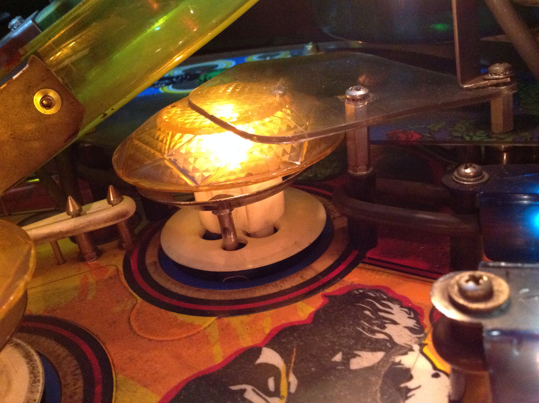
The left pop bumper on Guns N' Roses is activated in one of two ways: balls in play coming down the ball guides at the top of the playfield and hitting the right side of the bumper, or by the captive ball being struck upwards and hitting the left side of the bumper. This is a cool way to utilise an area to the left of the pop bumper which may otherwise go to waste.
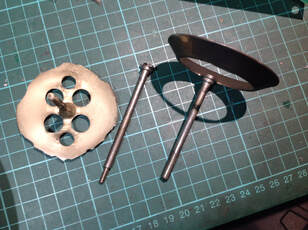
The issue with this pop bumper was twofold. First, the space underneath the pop bumper, which the bumper skirt dips into when depressed, was full of playfield glass. The glass on this machine had been smashed at some point, long ago, and there were still fragments everywhere. A couple of rollover switches at the rear of the playfield weren't working because there was glass stuck in the playfield cutout. So, make sure you check the depression for debris because it can block the skirt from being depressed. Once that area was cleared of debris, the next problem could be dealt with. The most important parts of the bumper assembly, the skirt and the rod and ring assembly, were totally destroyed. The skirt was chewed out badly on both sides, and one of the rings had broken off the rod and ring assembly. Not only that, but the other rod on the assembly had snapped at the base were it connects to the yoke, so this bumper was never going to work in this state. The pop bumper assemblies on Data East machines are great. They are so much more serviceable than Williams or Gottlieb assemblies as you can unscrew the entire assembly from the bottom of the playfield after removing the bumper cap. You'll have to cut or desolder the wires for the lamp in the bumper, too. Once that was done I could replace the skirt (part no. 545-5098-00, RTBB, Mr Pinball, PSPA) and rod and ring assembly (part no. 515-5085-00, RTBB, PSPA, Mr Pinball). Once the parts were installed I had to readjust the spoon so the skirt would trigger the switch properly. Then it was good as new. No metal posts in front of ramps
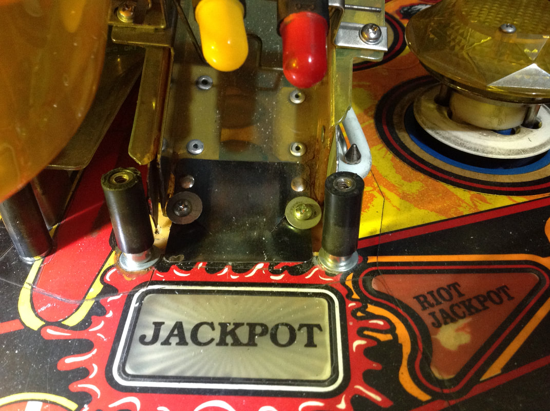
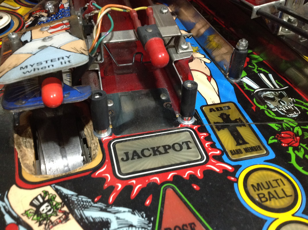
It's a basic premise of pinball playfield design. Plastic ramps need metal posts in front of their entrances to protect them from being destroyed. Metal ramps can do without them, but for plastic ramps, it's a no-brainer.
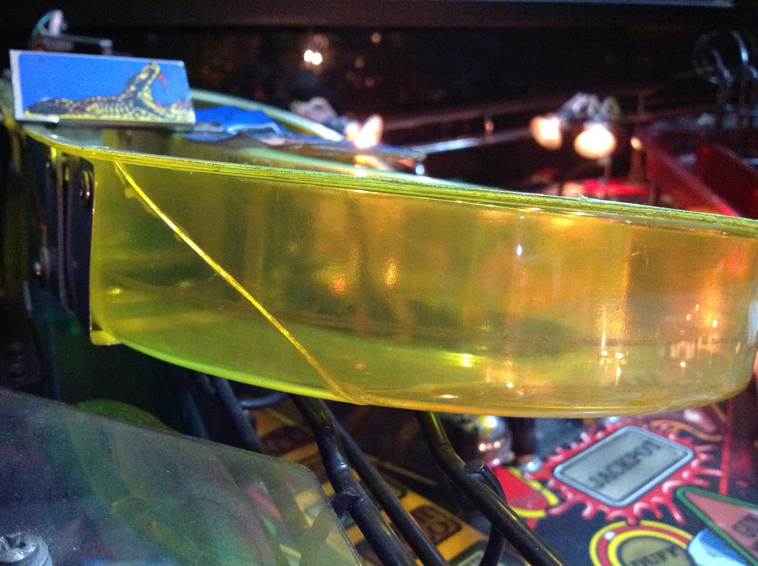
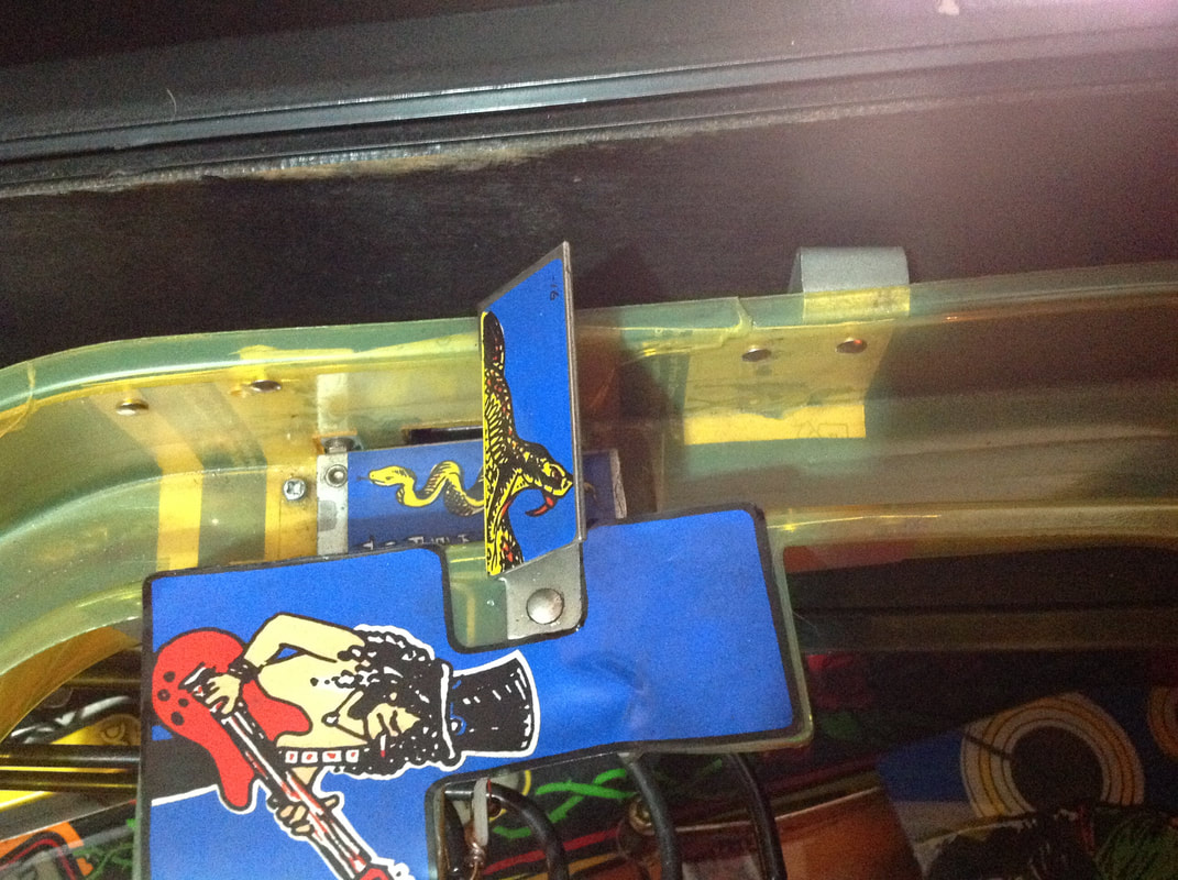
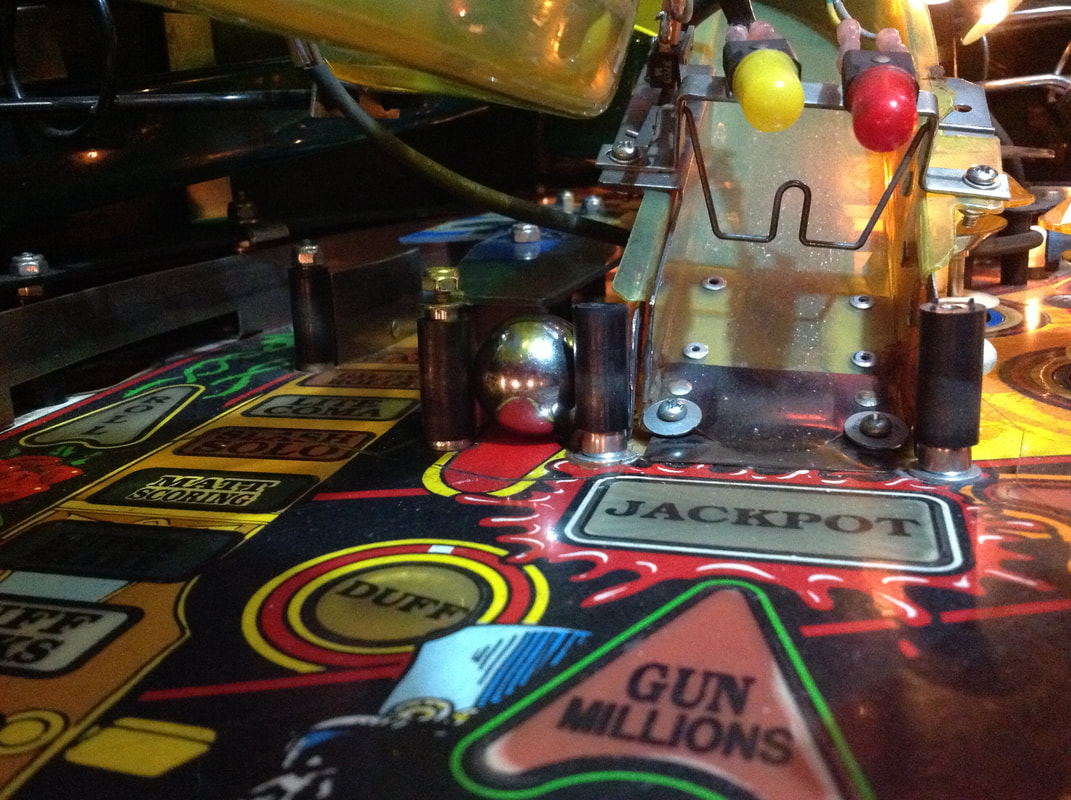
The problem is that Data East posts are shit. They're thin, and they break. There are several of these posts on Guns N' Roses, and two in front of each ramp entrance (part no. 530-5127-00, RTBB). Of course, when these posts break, they expose the (extremely valuable) ramps behind them. Some operators, who don't have replacement parts on hand, come up with creative ways to protect the ramps instead! These ramps had taken an absolute beating. Normally there are metal protectors which protect the ramp entrances from side impacts. However, these were either missing, or damaged themselves. While the ramps were already damaged, there was no sense in leaving them to get damaged even further. So, I removed the woodscrews and the one remaining post in front of the R ramp in order to replace them all. But first, I needed to fix the hogged out holes which the loose posts had been rattling around in. I used some Selley's Knead It (Bunnings) to fill the holes completely, and massaged it into the hole from the topside until I could feel it protrude from the bottom. Then, I scraped the excess from either side and flattened the putty out as much as possible before leaving them to cure for a few hours. There was still a fair bit of excess putty on a couple of the repaired holes, so I sanded it back until it was flush with the playfield. At that point I was ready to drill the new post holes. For the new posts, I used thicker and stronger Williams #10 metal posts (part no. 02-4659-1, RTBB, PSPA, Mr Pinball). I don't see the point in using crappy Data East posts which clearly aren't up to the task! The posts are located mid playfield and get a lot of direct ball impacts, so the stronger they are, the better. The problem is that as these posts are thicker than the original Data East posts, they require the playfield holes to be drilled a little wider. Select your drill bit accordingly, based on the size of the chosen post thread. After drilling, I found that the posts were still a very tight fit, so I hammered them in with a rubber mallet. Repeat that same process three times for the remaining three posts, and you're done! All four holes in front of the ramps should be good to last another 25 years. Some fresh rubber sleeves on the posts were also installed. Once upon a time, these ramps were pure unobtanium. Used and NOS ramps would sell for up to $500 easily. Once the supply of NOS ramps dried up, people started to get worried. The G ramp, in particular, is very fragile. The ramp actually sits quite loosely in the game, and is only secured to the playfield via the ramp entrance screws and the wireform it feeds to. Because of this, and the way the ramp flexes and bends, it gets broken frequently due to impacts from the trapdoor flap, stray balls, and general fatigue. Thankfully, there is now a solution. Pinsider Freeplay40 has recreated the G and R ramps with stunning accuracy, complete with vivid red and yellow colouring. These replacements are a great option if your original ramps are cracked or missing. While they are expensive, they are better than the original ramps in every way, and it is great to know that guys like this are around to keep the hobby going into the future. Captive ball missing
This was a funny problem to find, because I didn't even realise that Guns N' Roses had a captive ball in it until I looked at some reference images. On this game, the captive ball was completely missing and the post to the right of the captive ball was not in place properly, so balls could easily fall out of the captive ball area. I was under the impression that you were just supposed to shoot your ball in play up the captive ball laneway and towards the DUFF targets. I thought it was really cool how there was a separate area for the ball to enter and interact with the pop bumper!
But, it turns out that that is not how the game is meant to be. The captive ball must have rolled out and away because the plastic above it and the post to the right of it was broken. Once the posts were repaired (see section above), the captive ball could now be installed and locked into place. While this was how the game is mean to be, it certainly made Duff Rocks mode a lot harder to complete! Dot matrix display outgassing
As with any consumable part, the dot matrix display eventually wears and and requires replacement. This display was working but would be very dim on startup, and some sections of the display would not light up properly. One vertical line was also out on the display. During gameplay , the display was generally readable, however the text on the screen all but disappeared when you went into the audit or diagnostic menus. I checked that the display was definitely the problem by verifying voltages to the display were in spec (they were) and that all cables were working properly (they were). When those things checked out, I installed another display and it worked perfectly. Out with the old, in with the new! Battery corrosion on battery holder
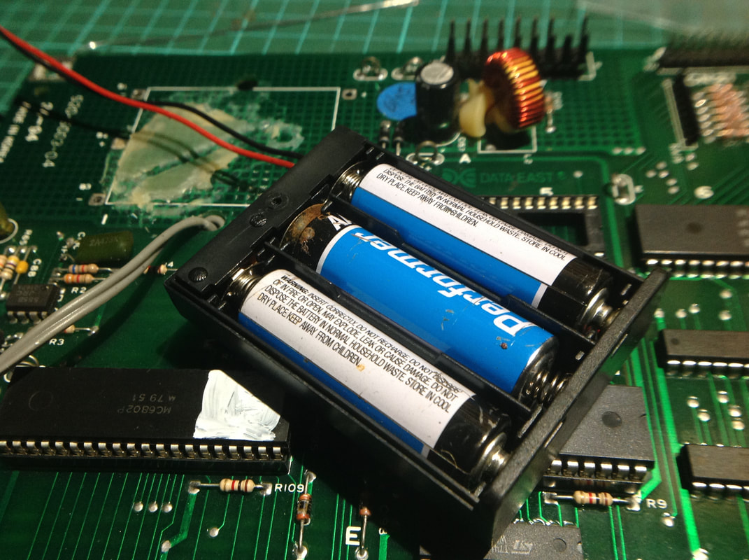
This issue almost went completely undetected and I only noticed it because I was curious how old the batteries were. A remote AA battery holder had been installed on the board (awesome!). Normally, I wouldn't fiddle with a working battery holder, but I wanted to make sure the batteries were in date as I already knew this machine had been sitting unused for several years. One of the batteries had indeed started to leak and corrode, and had damaged the terminals on the battery holder. Yuck.
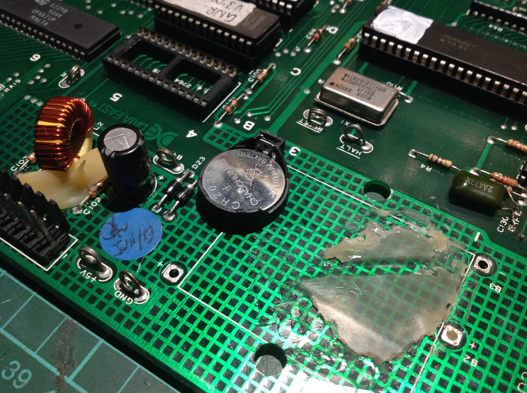
This was a quick fix, as I just removed the battery holder entirely and installed a coin cell battery holder. The lithium coin cell won't leak as easily, and a battery mounted to the board means you don't have to keep fiddling around with a remote battery pack, either! Flipper board fuse clips
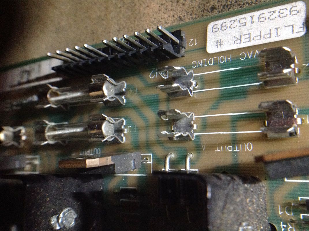
While inspecting the solid state flipper board on the inside of the cabinet, I found that some of the fuse clips had been mucked around with. A few of them had zipties wrapped tightly around them, in an attempt to secure a broken or cracked fuse clip. Data East used crappy fuse clips and their breaking is a common issue as discussed on Pinwiki. The solution in these cases is to simply replace them (Jaycar). There were four fuse clips on the flipper board which were cracked or entirely missing one side. They weren't causing any flipper issues yet, but it was only a matter of time until they did. So, I did some preventative maintenance and replaced them.
Trough switch faults
Occasionally, two balls would be ejected into the shooter lane at the start of a new ball. This seemed to happen sporadically. I did the simple stuff such as checking the trough switches for correct operation, and checking that the correct number of balls were in the game. Nothing suggested anything was wrong.
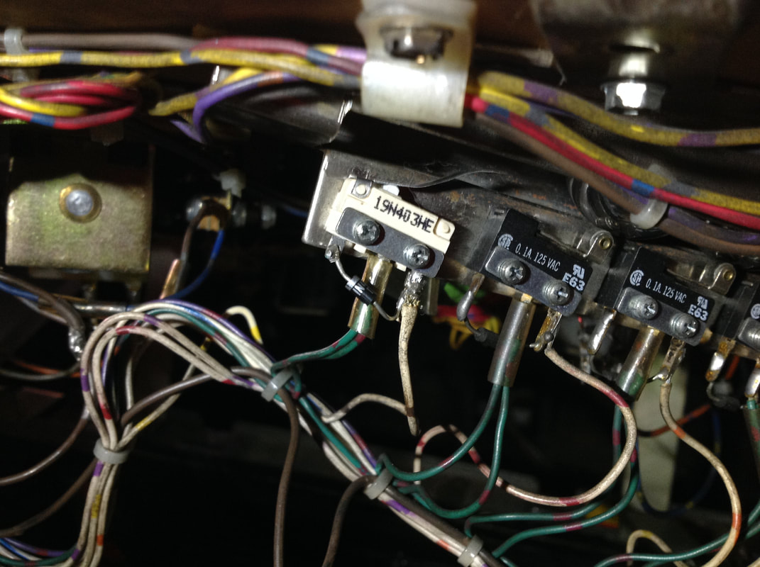
Taking a look at the trough switches, I saw that the leftmost switch was unoriginal and appeared to have been replaced at some point in the past. While inspecting the switch, I tugged on the green-brown wires attached to the centre lug. There is usually a small piece of insulation covering these wires where they connect to the switch lug, but the insulation had fallen further down the wire. The game was in switch test mode at this point, and as I played around with the wires, I heard the switch open and close. Bingo! The green wires were soldered poorly to the switch, and some loose conductor strands were actually touching the frame of the trough assembly. This was causing phantom switch hits on the leftmost switch. This was making the game think there were still six balls in the trough, causing it to serve another into the shooter lane. Stripping and resoldering the green wires to the switch fixed the issue. Make sure the small strip of insulation is covering the solder joint and the switch lug; its job is to prevent this kind of issue in the first place by isolating the switch wires from other metal parts. Mystery hole lamp not working
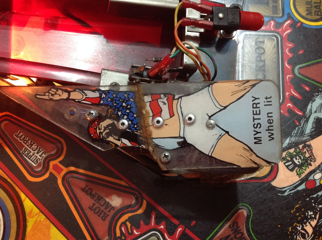
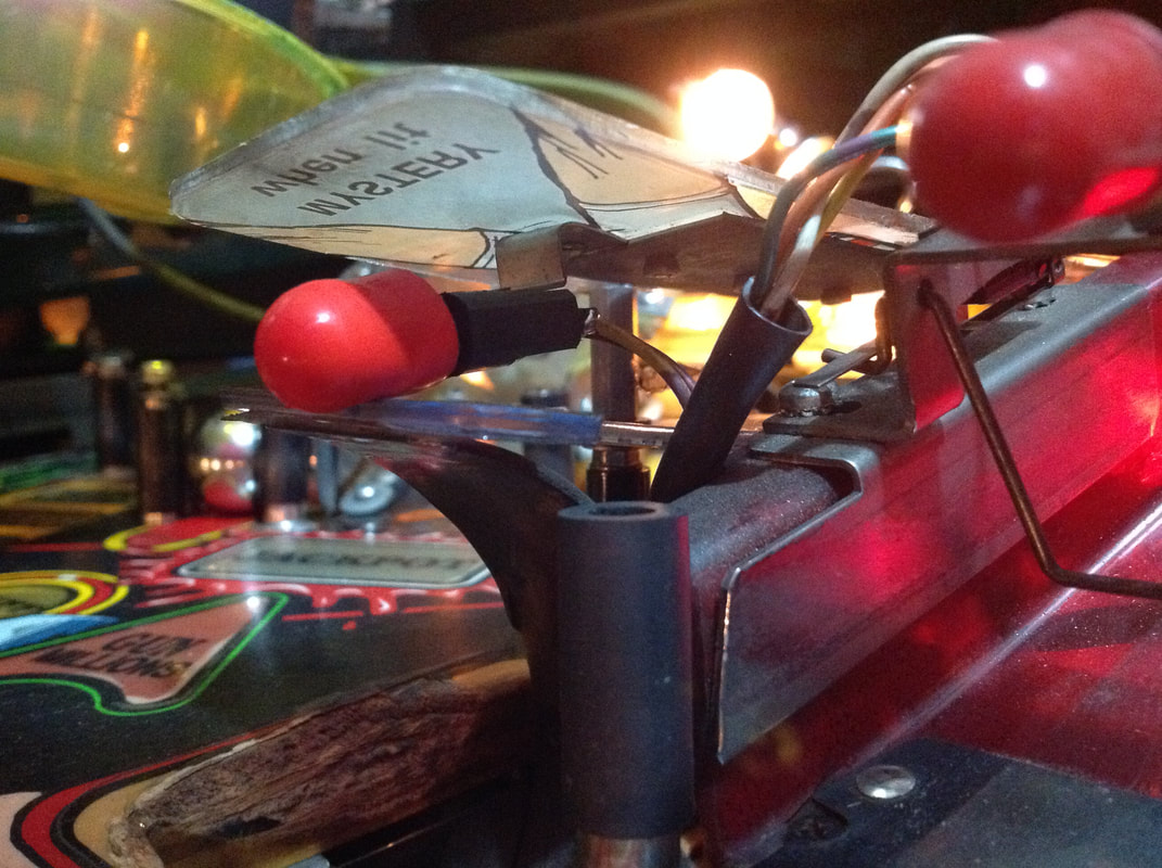
The lamp above the mystery hole wasn't working at all, and after elinating the bulb as the issue, I started to take the plastics in this area apart so I could see what was going on with the lamp socket. This socket is mounted to the underside of the Axl plastic. As this plastic is in contact with the scoop, it suffers a lot from vibration as balls enter the scoop and get ejected. It also gets hit directly with the ball sometimes, which doesn't help.
The Axl plastic on this machine had been totally destroyed and was held together with a bunch of rivets and glue. It wasn't pretty. However, it worked. While it wasn't necessary for this machine, new plastic sets are available locally (RTBB). The problem turned out to be that the wires connecting to the lamp socket were both broken off. Stripping and resoldering them got the lamp working again. When everything was reassembled, I did notice that the lamp socket was bent downwards slightly, meaning that the lamp was resting on top of the plastic piece directly above the scoop. This meant that it was absorbing a lot of vibration and at greater risk of getting struck by the ball. So, I bent the lamp socket bracket as far up as possible so the lamp would stay out of harm's way. Conclusion
What started as a simple request to fix a couple of small issues ballooned out into fixing a huge number of problems, as it normally does with pinball. But, now that the issues have been fixed properly, this game will be ready to rock again! This machine had had a hard life because it was an operator's machine which was hired out regularly. It had sat dormant for several years until the owner decided to get it fixed up. I love that it will now be going out on hires again and working properly. As this was a basic fix-up job, there were no fancy LEDs or rubber rings installed. Simple incandescent globes and black rubber rings were put where needed, and a light playfield polish was done. I took the opportunity to clean things a bit when I took the G and the R ramps off, too. All of the in-game diagnostics were run through to make sure all was in good working order before I let the owner know that their machine was ready for pickup. I can see why people say this is Data East's best pinball machine. It's got great music, the playfield has a lot of shots, and the multiballs are insane (especially when the magnets are working!). It can be a game dominated by multiball, or simple mode progression, depending on how you like to play. However, if you don't like listening to Welcome to the Jungle, you definitely won't enjoy playing this game, as it plays constantly! Ain't Goin' Down is an interesting track to hear on this machine, too. This game easily gives some of the more modern rock-themed games a run for their money. There are rumours that Jersey Jack's next game will be a remake of Guns 'N' Roses... I just hope it doesn't have any more magnets...
14 Comments
Ryan
9/11/2020 07:27:58 am
This is a very helpful page... good stuff! I've been getting an "Open The Door" message on my GnR at startup. It's annoying because it resets everything to factory settings. Manual says to check battery voltage at CMOS RAM. I have no idea what that means but after reading through your page, I'm wondering now if it has to do with the battery on the board.
Reply
Hi Ryan,
Reply
Ray
8/2/2021 07:48:23 am
Can you tell me what resistors or components and on which circuit board controls the # 44 lights in the BACK BOX in Guns N' Roses.The top row lights do not come on. Thanks
Reply
Hi Ray,
Reply
22/2/2022 11:29:34 pm
Hi The dot matrix has just stopped suddenly working all together...is tat normal? can it be regassed or fixed? or you have to get a new one? I'm in Australia any tips or where to get a replacement appreciated, I'm thinking of changing globes to led's do you suggest frosted, anti ghosting or? do you know how many needed? and are what types or are they all ie 44 or 47? Some say if 44 put 47s in?
Reply
Hi Robert,
Reply
Robert
23/2/2022 11:12:48 pm
Hi Alex
Robert
21/2/2024 10:32:40 am
Hi Alex The connections were the issue all good now, THX! Have replaced all globes with leds looks much better and new silicone bands, now I have an issue with the "slash" drop trap door on the yellow plastic ramp (left side) not working, any ideas?
Hi Robert
Peggy
19/10/2022 10:17:35 am
I have one I would like to sell. Works but needs refurb.
Reply
Hi Peggy,
Reply
Nicole Rolak
18/10/2023 02:56:27 pm
Factory reset when we open the door. We have replaced the batteries but we can’t get into the game menus or diagnostics. The prompt is play field high power disabled by coin door interlock. Does that mean anything?
Reply
Hi Nicole,
Reply
Leave a Reply. |
About
Here you will find logs of our pinball and arcade machine restorations, repairs, discussion about general pinball and arcade topics, as well as recounts of our random pinball adventures.
Check back regularly for updates! Blog updates
Archives
May 2024
Categories
All
Donate

Running this website is a hobby for me (just like pinball!). I like being able to show off my restoration work so everyone can learn from it and potentially fix their own machines. If you enjoy reading the site's content or it has been helpful to you, please consider donating to offset some of the website's operating costs. |


 RSS Feed