- Published on
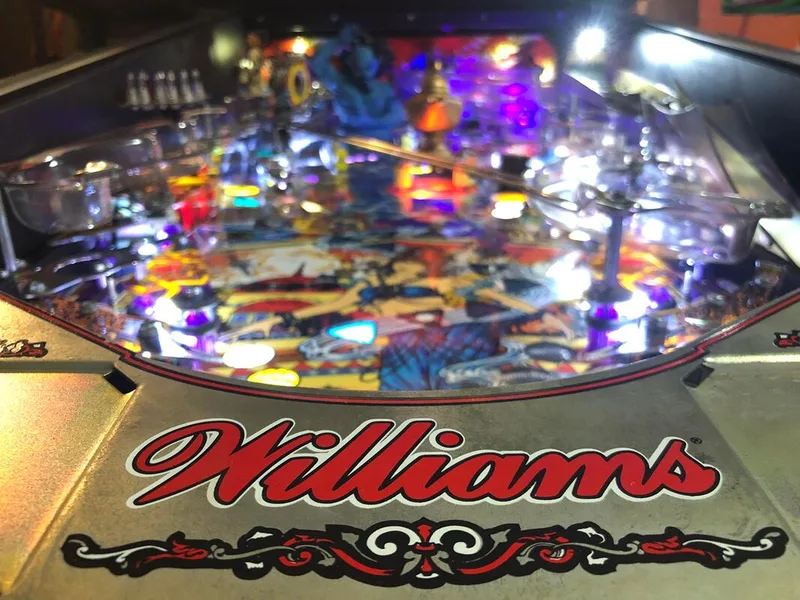
Tales of the Arabian Nights
- Author
-
-
- Name
- Posts
- Posts
-
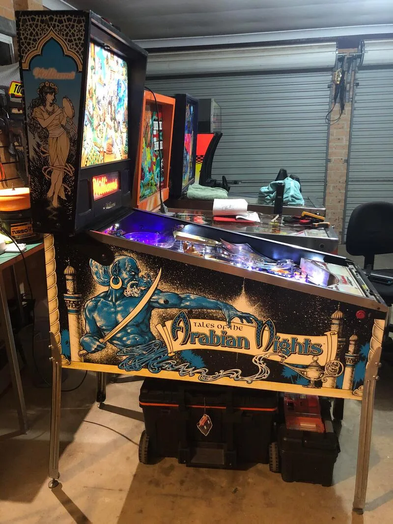
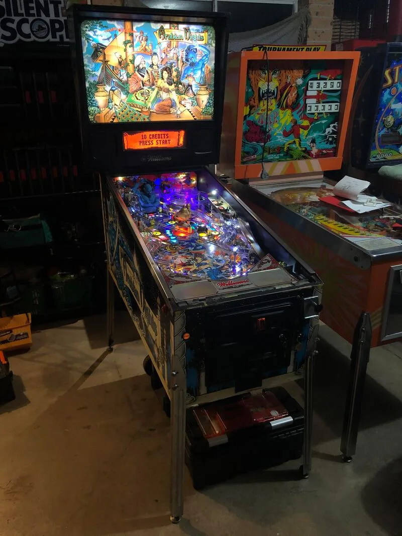
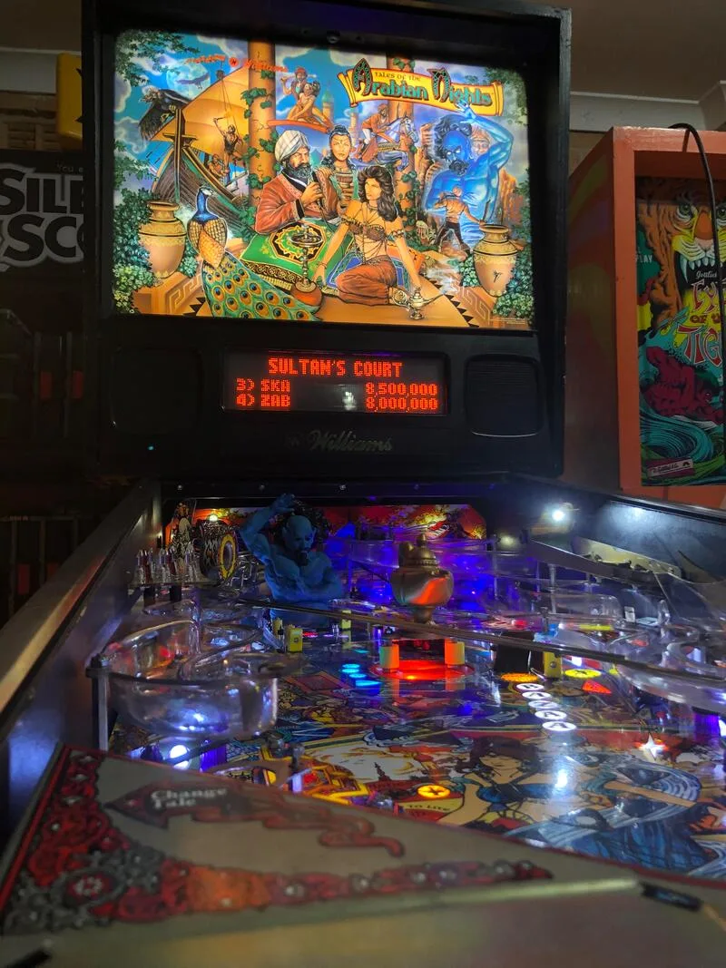
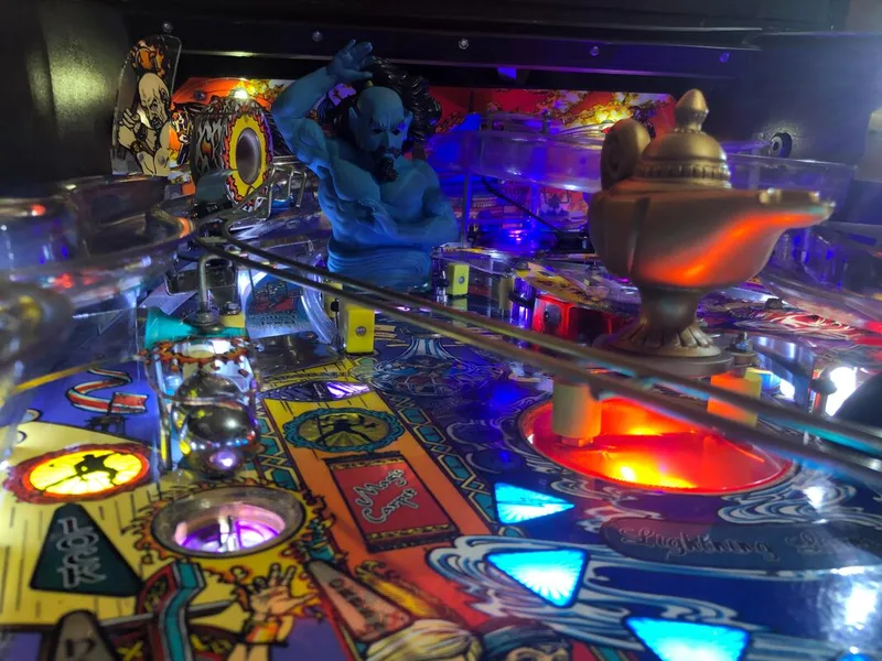
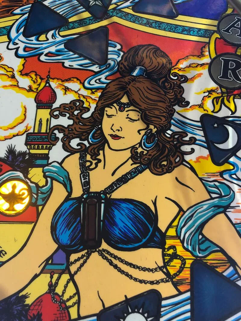
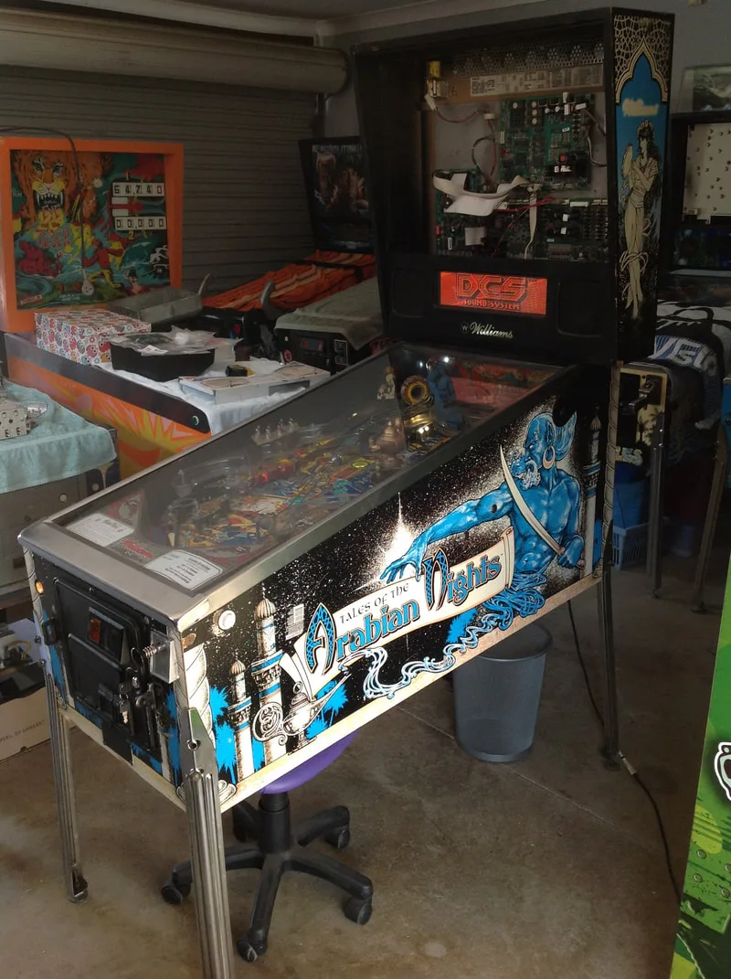
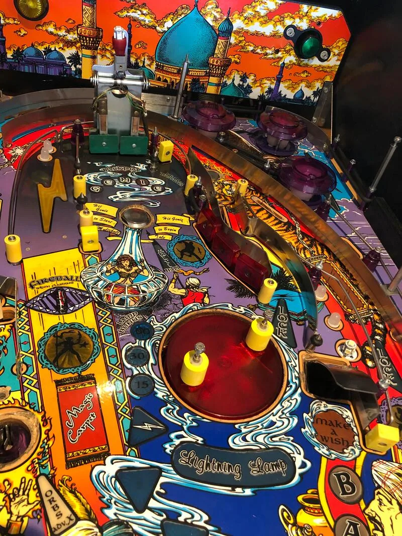
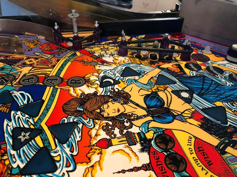
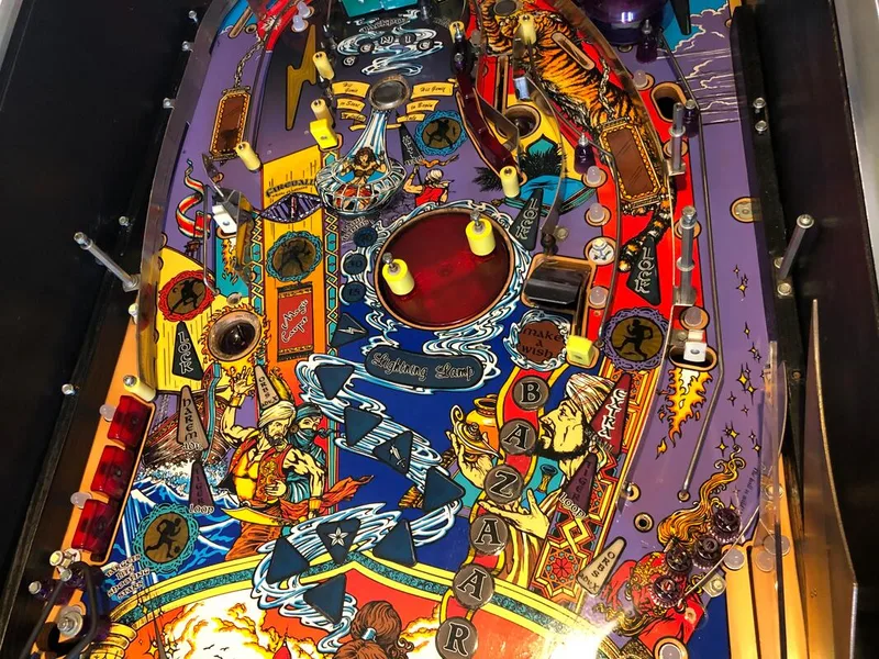
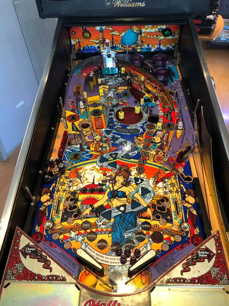
Ever since she first saw it, Tales of the Arabian Nights (Williams, 1997) has been Fiona's favourite game. She loves the artwork, the colours, the sounds, and everything else about this game. And I don't blame her. It really is a beautiful game, and really gives you that feeling of being in a "world under glass" when you're playing it. I think Tales of the Arabian Nights has the best unlicensed music of any pinball machine ever made. The end-of-ball bonus music tune is one of my favourites - featuring what I assume is a qanun playing from higher to lower notes as the lamp bonus is counted down - it almost makes me want to lose my ball just so I can hear it!
So, when the opportunity to restore one of these games presented itself, we jumped at the chance! Unfortunately, by the time we finished the restoration, the game had almost killed us, but it was worth it for the chance to bring this beauty back to playing like new.
- Timber in good condition.
- Side artwork in average condition.
- Translite in good condition.
- Legs in poor condition; bolts were covered in glue and one leg bracket was stripped.
- Playfield was very dirty.
- Consumables (rubbers and lamps) in average condition.
- Playfield artwork worn around the vanishing magnet, tiger magnet, and in playfield artwork areas including the left loop flasher insert, lamp insert, fireball lamp inserts, and in captive ball areas.
- Plastics in poor condition; some broken and some replaced with clear pieces of plastic.
- Playfield mechanisms/toys in poor condition. Vanishing magnet did not work.
- Some strange playfield modifications (switch locations).
- Damage to ramp flap.
- All mechanisms and assemblies in average condition. Pop bumper did not work.
- Consumables (coil sleeves, flipper parts) dirty and in poor condition.
- Damage to playfield timber from hogged-out screw holes.
- Machine booted up and played.
- Backbox circuit boards in poor condition; multiple hacks and poor wiring jobs present.
- Dot matrix display did not work properly.
- Coin mechanism did not accept coins.
- Playfield and backbox wiring in good condition.
The game was not in the best of shape. According to the owner, it had been on location for as long as he could remember and had not had a single service in that time. So, as expected, the game did not play well, and had multiple obvious issues which would prevent anyone from playing it in the first place! The aim of this restoration was to give the machine a do-over, get it fully working, and allow it to go back on location to earn more money.
Disassembly
The first thing you'll notice when disassembling Tales of the Arabian Nights is that all of the ramps are connected to each other. There is only a single ramp entrance on the playfield, and a diverter sends the ball to the left or the right ramps. Be very, very careful when handling these ramps. The plastic is thin, and since the ramp pieces are quite large, breaking them is a (costly) possibility. If you do break a ramp, or you just want to replace it, you can rest assured because they can be replaced either individually or as a set (RTBB). The swirl ramp (centre piece) is particularly flimsy, so be extra careful with it.
Swirl (centre) ramp in place on the playfield.

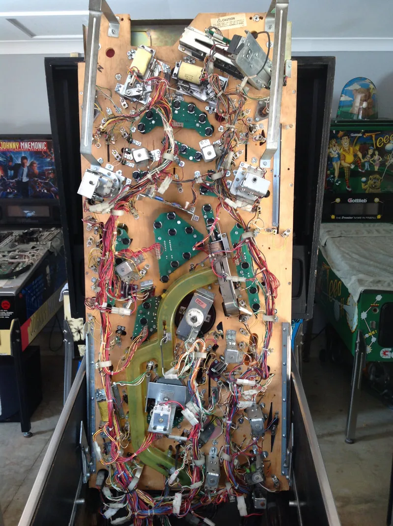
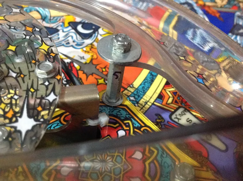
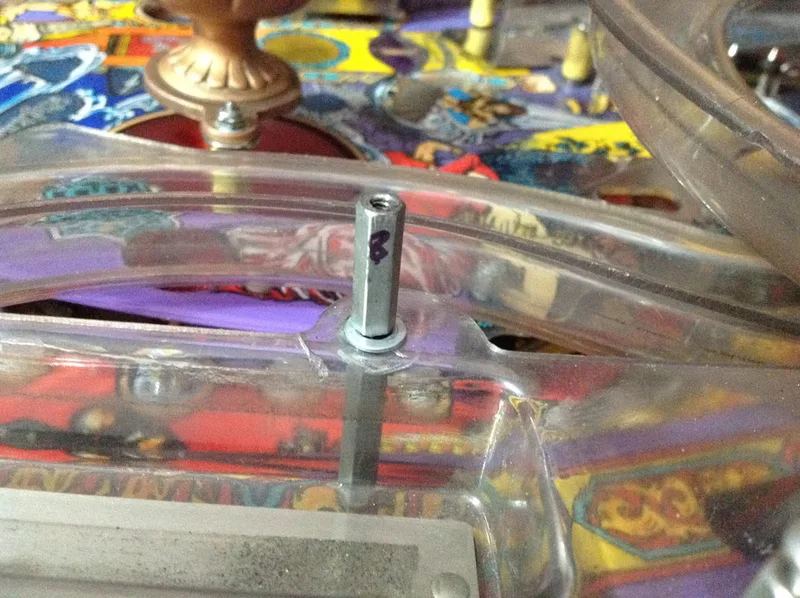
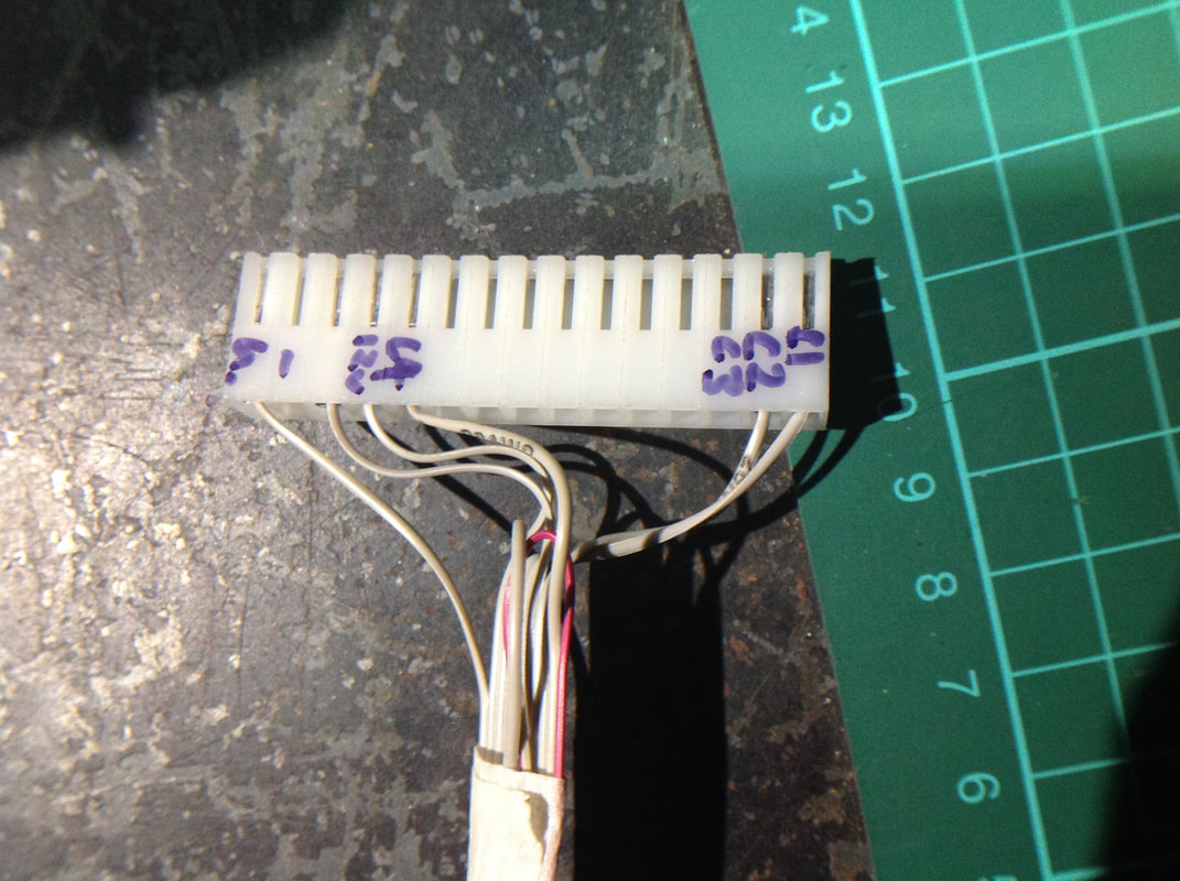
A side effect of having so many ramps on the playfield is the fact that you need a lot of posts to support and secure the ramps to the playfield. Tales of the Arabian Nights has a lot of hex posts, and if you don't remember where they belong, you'll have a really bad time when it comes to reassembly. I decided to number each hex post with a marker, then take a photo, so I knew which number post went where. If you have trouble figuring out where the hex standoff posts go, and you forgot to label them or take pictures (naughty, naughty!), Pinside user mwong168 took some life-saving pictures of each post's location with a measuring tape beside it so you can verify which length post goes where.

Numbering hex posts will make life easy when it comes to reassembly.

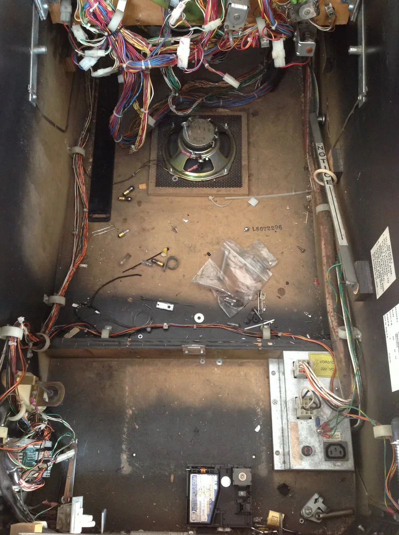
Otherwise, disassembly of the game is pretty straightforward. Start with the swirl ramp before removing the left and right ramps. There are multiple switches and coils attached to the ramps, so be sure to disconnect them under the playfield before removal. The skill shot assembly is attached to support posts by three screws, and can then be simply lifted off. Note that the end of Section 1 in the game manual (page 1-49) contains instructions on how to disassembly the lamp, shooting star cage, and genie assemblies. Other playfield assemblies and plastics are screwed down with the typical screws and nuts; no unusual hardware is required. Below are some photos of the machine's condition (as received) and some of the disassembly process.


Tips & Troubleshooting (click on sections below to view details)
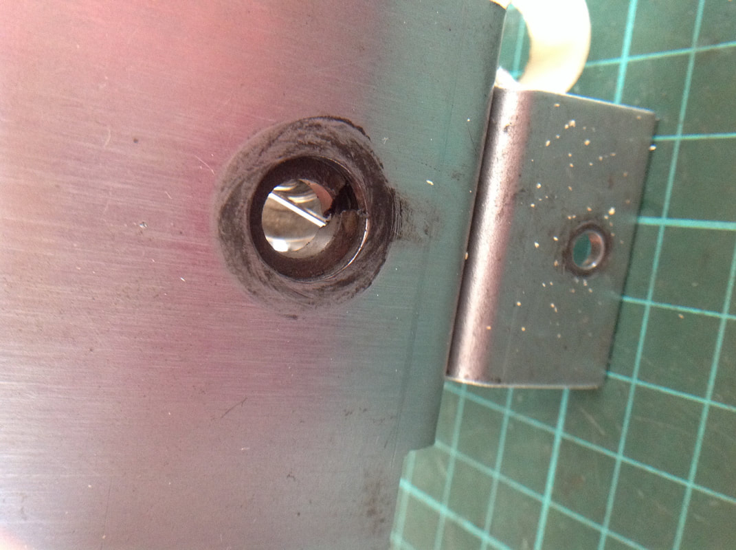
Luckily, a coin door lock is no match for a drill. I learned my lesson from trying to break into the door on my Getaway using a cheap drill bit, which turned out to be weaker than the lock barrel, and snapped in half. But this time, I was prepared, and had some titanium bits at the ready. Use a drop or two of oil on the end of the bit to lubricate it while drilling, and choose a bit which is slightly larger in diameter than the barrel of the lock. This will create a snowstorm of metal shavings, so put something down on the ground to make cleanup easier.
Once you're done, simply remove the remains of the lock barrel from the door and replace with a new lock. You can get standard coin door locks from most local suppliers (PSPA, RTBB, Mr Pinball). Alternatively, if security is not a great concern, there are plenty of economy locks available, too (eBay). Thankfully, once the coin door was open, I found the backbox keys attached to the rear of the door, so accessing the backbox was no problem.
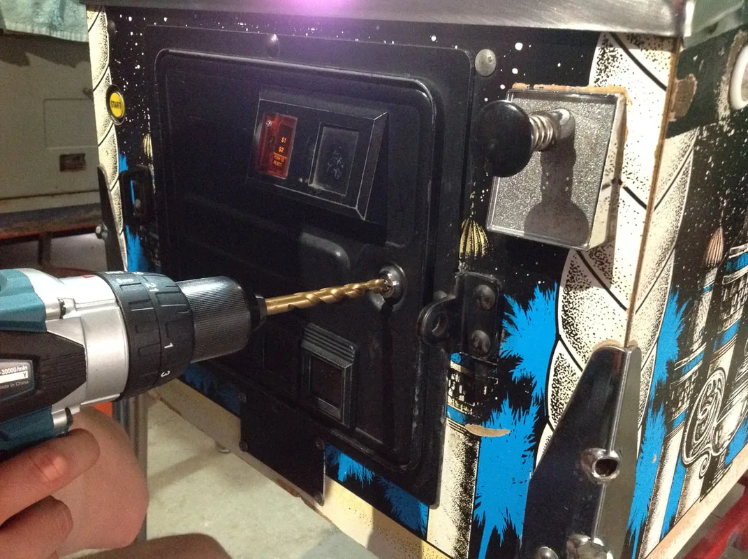
Commence drilling!

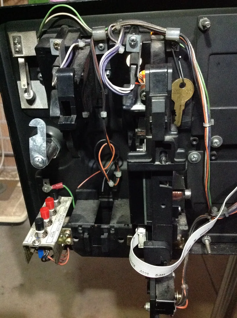
Interior side of coin door, showing new lock barrel installed (left) and key for backbox (right).

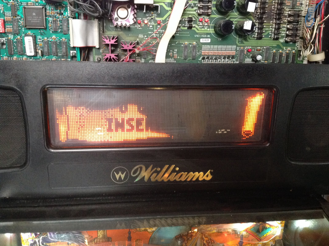
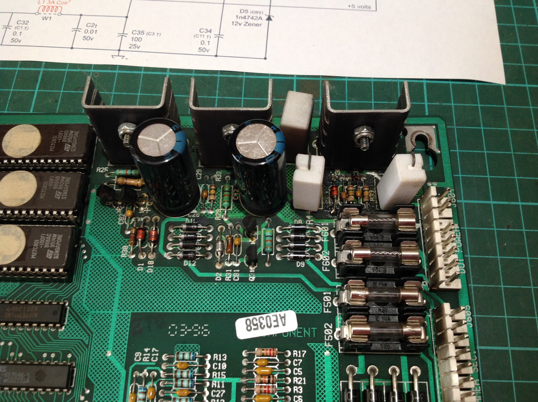
Made in 1996, Tales of the Arabian Nights is a WPC-95 game. There were major changes to the WPC boardset when it was upgraded from the WPC-S to the WPC-95 system. These included the amalgamation of the previously separate sound board (part no. A-12738-50004) and the dot matrix controller board (part no. A-14039) into a single, audio visual board (part no. A-20516-50047). This was the first time I had had to rebuild boards in a WPC-95 system, so I was looking forward to it.
Dot matrix display as received, with serious display artefacts
Display driver circuitry, component side
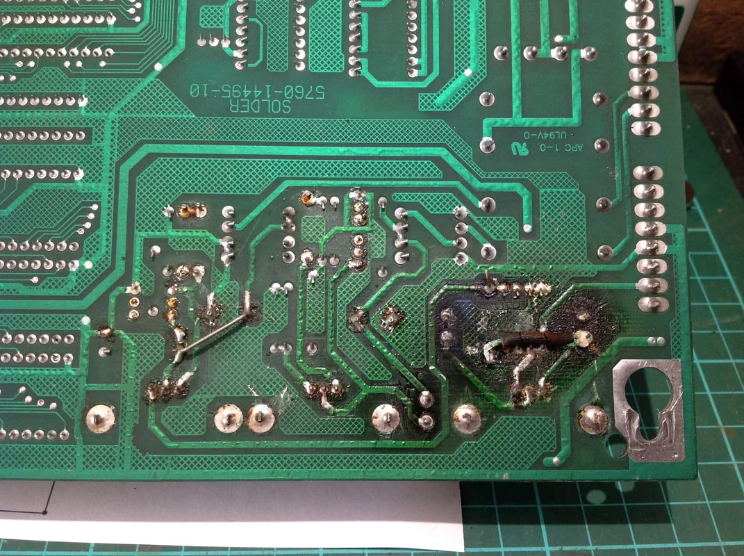
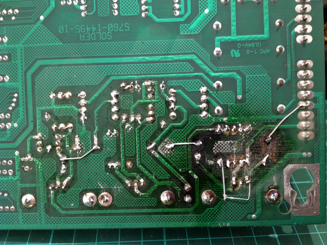
Display driver circuitry, solder side

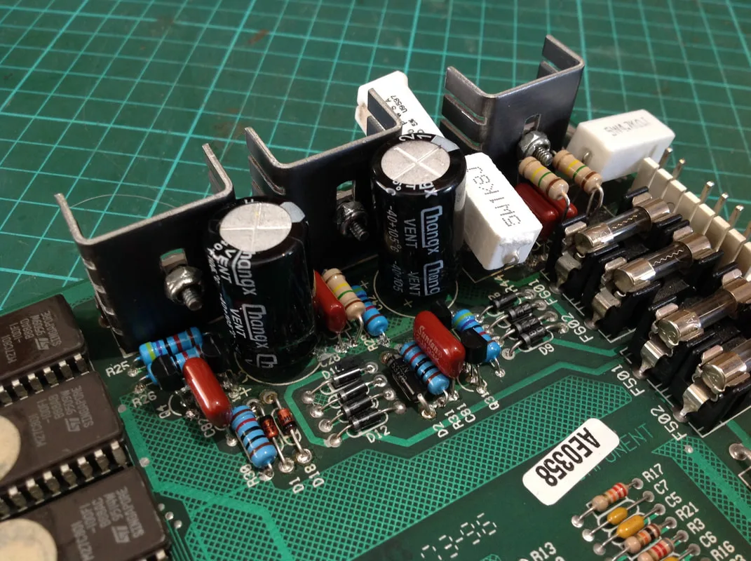
I pulled the audio visual board out of the backbox for a closer look. The most heat affected part of the board was between R43 and D3. There was a jumper wire running between those two components, and another from C28 to Q6. A lot of the traces and vias looked to be in poor condition, so I was expecting some to be lifted and destroyed during desoldering. Unfortunately, with boards this old and with traces this damaged, further damage is almost inevitable. It took a coupe of hours of careful desoldering to get all of the components off the board. Some were difficult to remove and needed a couple of applications of fresh solder, followed by desoldering, followed by some more solder, then more desoldering. Once again, a desoldering station is worth its weight in gold for these situations. These kinds of jobs are impossible to do efficiently with a solder sucker or solder wick.
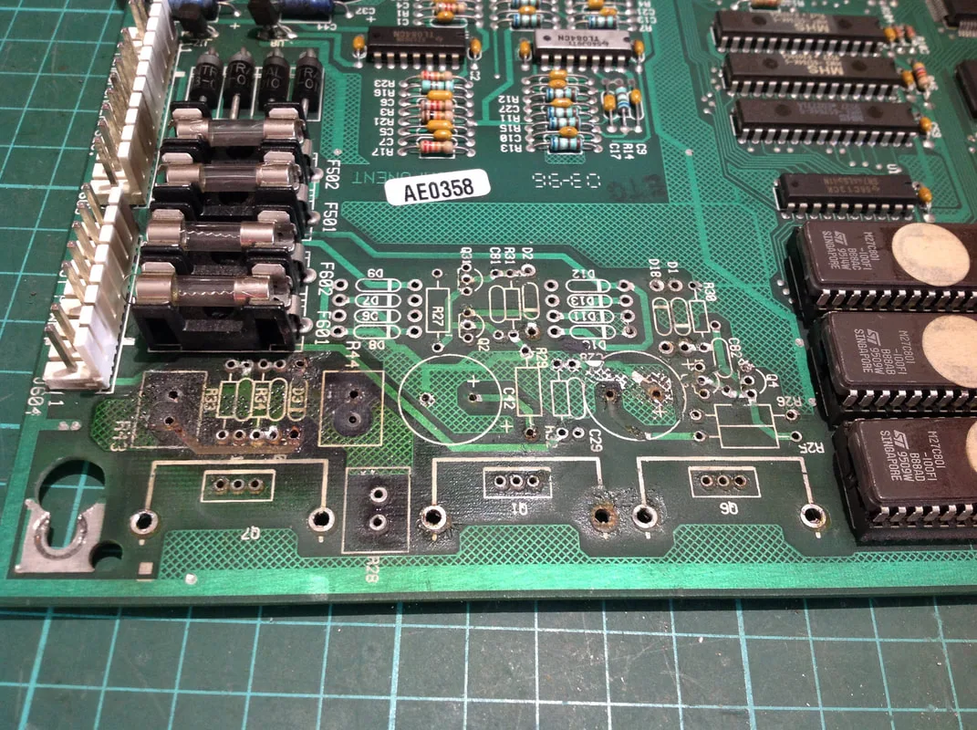
After component removal, component side

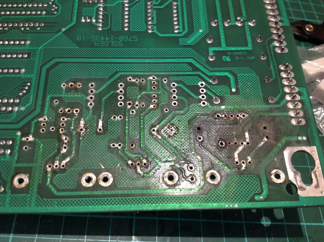
After component removal, solder side

All in all, I was pretty happy with the results. A couple of traces were already destroyed, such as the one from R43 to D3 that I mentioned previously. Others were a little dodgy, and needed jumper wires just to ensure they stayed solid in future. Only a couple of pads and through holes were damaged, but these were barely intact to start with. Once the new components were in place and some new solder was applied, most of the through holes would be OK. But first, I needed to gather the components I needed for the rebuild.
Most of the components are the same as those used on the dot matrix controller board in WPC-89 games. See my previous blog entry for a list of applicable components. Additionally, Pinwiki has a lot of useful resources for rebuilding this part of the board, including Richard Harvey's very useful quick reference guide which lists all of the components required on a labelled schematic. The main difference is you won't need as many 1N4004 diodes, but you'll need two extra 150K ohm resistors (Jaycar).
New components installed, component side


New components installed, solder side
Cleaning of the board with alcohol to remove the soot and debris actually made it look somewhat worse as you could see the fibreglass and lower layers of the board in the most damaged areas. However, cleaning the board thoroughly is important to ensure tracking faults don't develop in future and to ensure that there isn't any foreign debris on the board.
The traces that were originally damaged (or totally absent) were replaced with new jumper wires. Additionally, dodgy or now broken traces were supplemented with jumper wires as well, including connections between Q7 and D3, C28 and Q6, R43 and ground, and R44 and ground. Check all of these traces thoroughly whenever rebuilding this board as they are likely to be broken. R43 was in a particularly bad state as both vias were destroyed and the resistor was not securely attached to the board until new jumper wires were installed. However, once they were connected, the resistor stayed locked in place. I like to raise the new components off the board as much as possible to increase heat dissipation. This is good practice whenever replacing large resistors.
You'll notice that the capacitors depicted in the image above are actually Changx brand. Here's a pro tip: never use cheap, shitty capacitors on this board. These were the only capacitors I had on hand at the time, so I installed one to see what would happen. It worked great for a couple of hours, until I heard an almighty bang and found that C28 had ruptured, sending magic smoke everywhere. C28 is in the high voltage circuit, and specifically, the 125-volt circuit. Low quality capacitors are more likely to be underrated for the voltage they are used at, which can cause them to explode. So, the moral of the story is to always use high quality capacitors and not to use whatever you have lying around at the time! I placed another order for some higher quality capacitors (RS Components) and replaced both C28 and C42 when they arrived. Low quality and counterfeit capacitors are such a huge problem that there is an entire website devoted to listing who manufactures specific capacitors and which ones are legitimate (Bad Caps). Always check and new capacitor brands against the lists on Bad Caps to ensure they are of good quality.
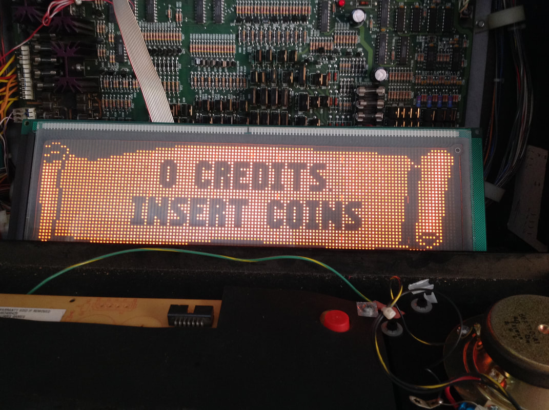
Once all of that was sorted, there was one last problem to solve. There was nothing showing on the display at all! I verified the voltages being produced by the board were correct, and that there were no connector issues. Next, I tried plugging in a known good display. Viola! It worked! When I plugged the original display back in, I got nothing again. Why is this? My theory was that the display driver was producing voltages way too high for the display, and once the voltages returned to normal (i.e. they were lower), there was no longer enough power to light up the older, aging display. Older, dying displays draw more power, so that is why a newer display worked on the lower voltages while the original, tired display did not.
At the end of the day, this repair was relatively expensive because it involved several hours of circuit board repair, and then the cost of a new display (part no. 5901-12784-00, PSPA, RTBB, Mr Pinball). However, everything that had failed has now been replaced, so this display and audio/visual board should be good for a while.

Display circuitry replaced, and a new display installed. Works perfectly!
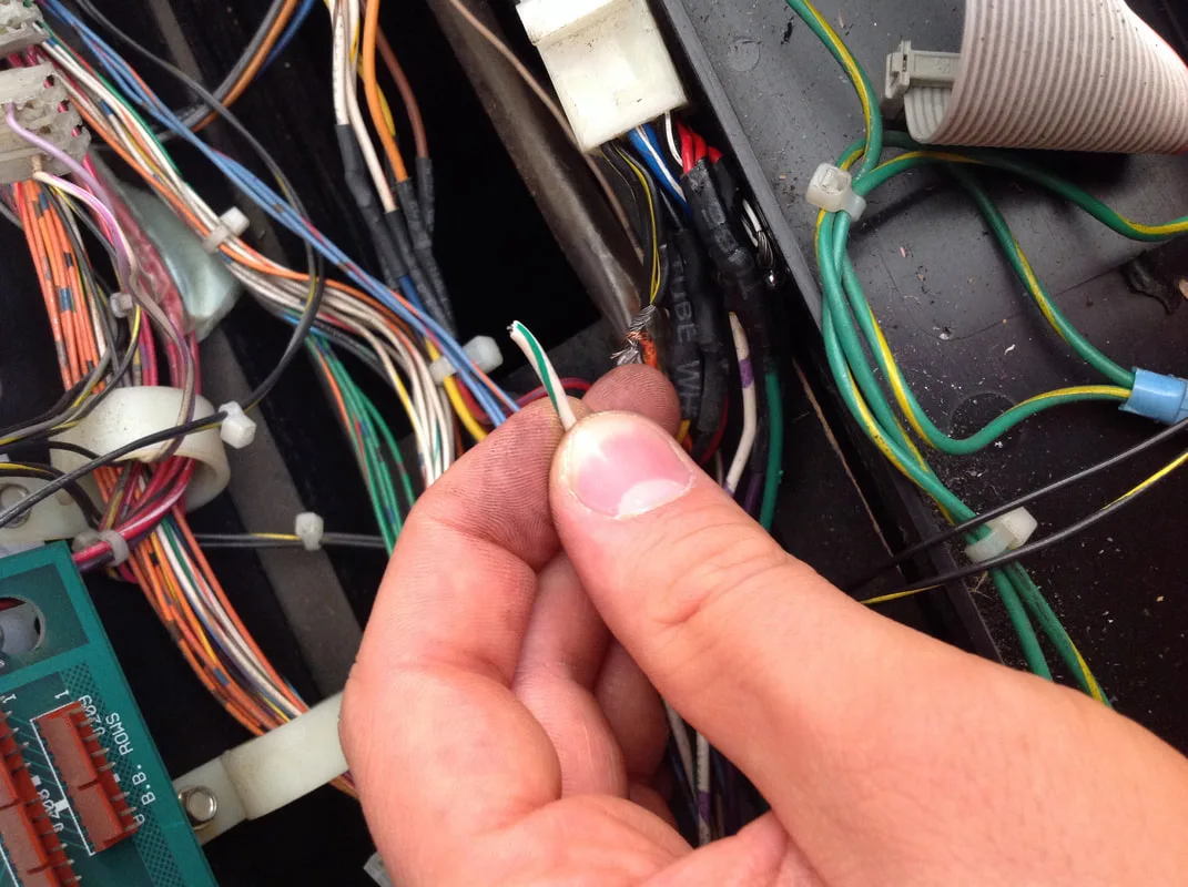
Backbox light panel return wire - loose!

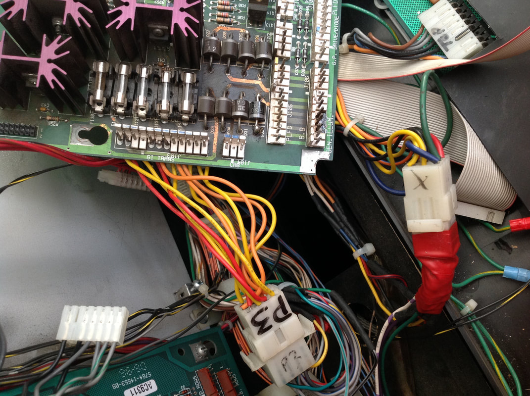
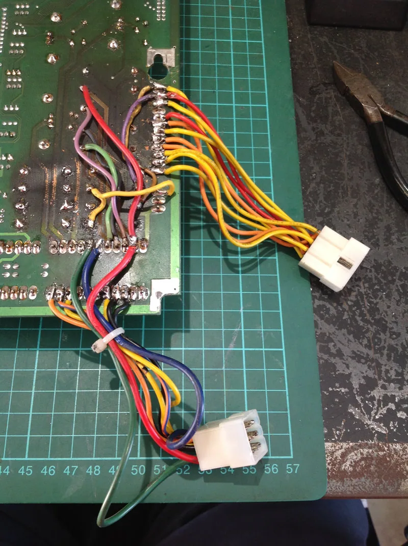
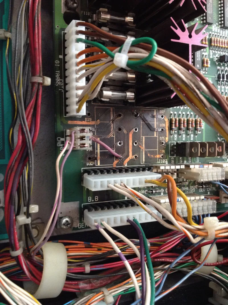
The next issue came when it was time to find the connector the wire had fallen out of. This is when I noticed how much of a total mess the wiring, particularly the GI wiring, was. In typical pinball repair fashion, somebody had soldered the GI wires directly to the solder side of the power driver board. They did this for both J103 and J106, as the original header pins were toast. But! In an attempt to partially atone for their sins, they installed a connector further down the line so that the power driver board could still be unplugged and removed from the backbox without cutting any wires off. Thanks, I guess? While this is a practical solution, it's ugly, and it's not how things are meant to be. So, the first step was to remedy this clusterfuck by desoldering all of the wires from the rear of the board, installing new header pins and connectors, and then cleaning up the components on the board itself. It was going to be a long road to recovery.

Odd connectors with wires soldered to header pins at J103 and J106 on the power driver board.
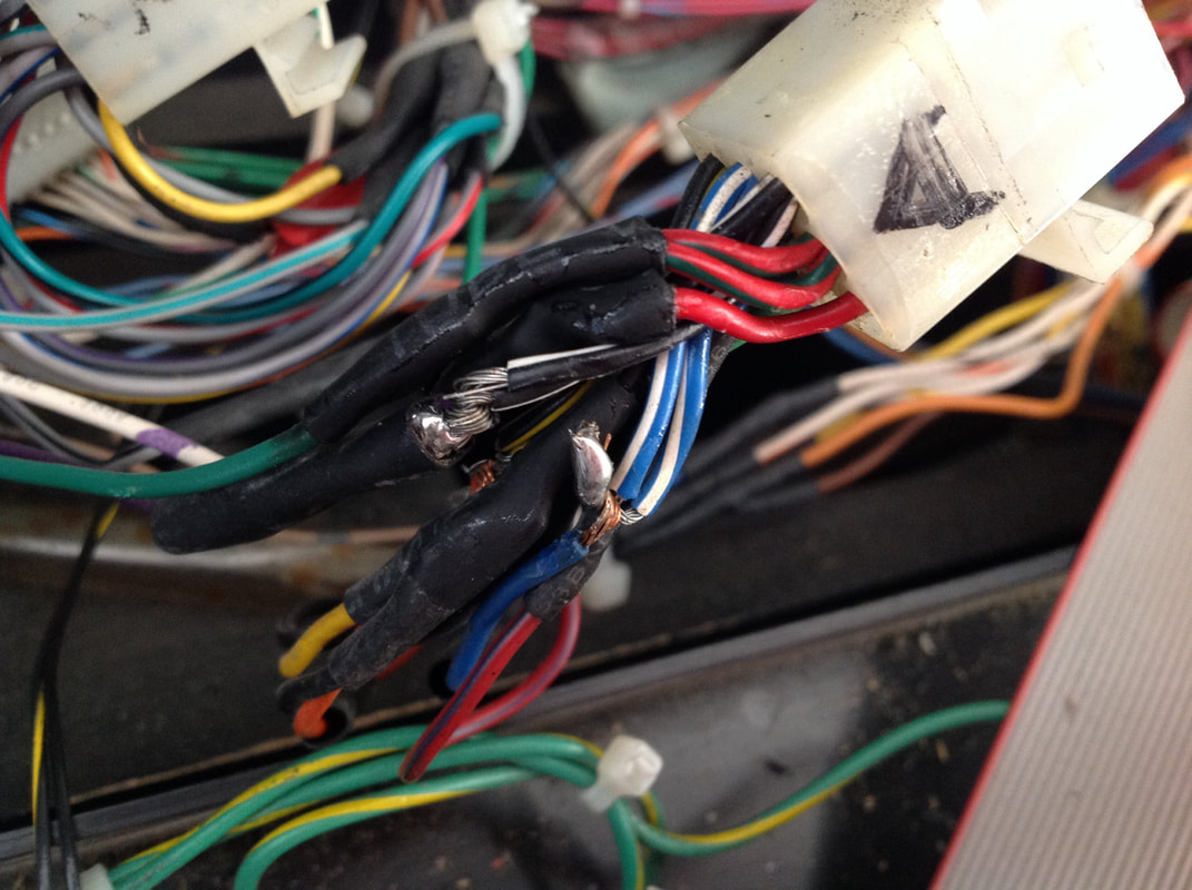
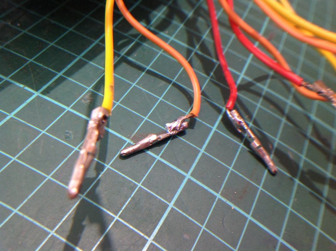
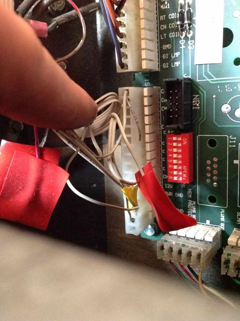
I was curious about the connectors that had been installed in place of the proper 0.156" IDC connectors which were originally present. This is where I discovered that, not only had the connectors been installed poorly, but the wires within had been crimped terribly as well. For starters, there were wire splices covered by electrical tape and heat shrink tubing (some not even soldered) connecting the original cabinet wiring to lengths of wire sticking out of the connector. Why? Because the connector had simply been cut from another game, and the wires originally installed in that connector had not been replaced, but simply spliced together with the wiring in TOTAN. God almighty. And if that wasn't enough, when I removed the wires from the connector housing holding the male pins, I discovered that somebody had actually soldered most of the wires to the top of the crimp terminals instead of actually crimping them in place. Once again, this was another attempt to reuse the pins already in the connector instead of doing the job properly and using new ones. No wonder the lighting in this game was shot - most of it wasn't even connected properly!

Poor connections from cabinet wiring to wiring already installed in the connector.
Wires soldered to the topside of male crimp pins.
At the end of the day, the best course of action was to cut everything from the cabinet wiring harness that had been hacked with, and start fresh. So, that's what I did. New connectors went onto the wires (RS Components, RTBB, Mr Pinball) with fresh crimp terminals on each (RS Components, RTBB, PSPA, Mr Pinball).
Before the connectors could be plugged in, however, I needed to pay some attention to the board itself. One of the changes that Williams made on the WPC-95 boardset was to the GI circuit on the power driver board. There are two GI circuits that are constantly on. Williams installed a series of 6A2 diodes in these circuits. The problem is that these diodes generate a huge amount of heat, which eventually destroys the board. The end result is that the board gets crispy, the traces are damaged, and the GI circuits can be totally severed. This had likely already happened in the past, which explained the spaghetti of jumper wires all over the back of this board.
Original spaghetti of wires and connectors soldered to the board.

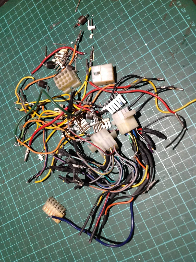
After removal of all old wiring. What a mess!

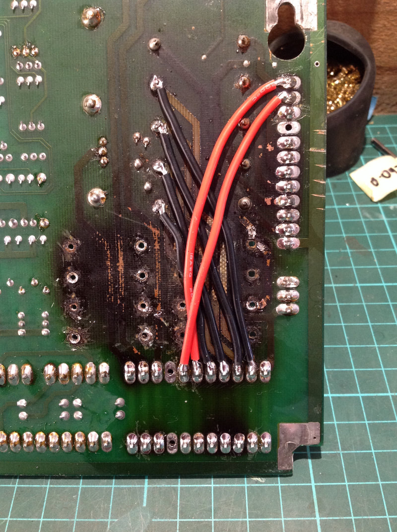
Pinwiki offers the best solution in these cases - just bypass the diodes completely, as they are not really necessary. Then you'll have no more heat problems, especially when LEDs are installed. I still had the issue of heat-damaged traces, though, so some additional jumpers were needed to connect the fuses to the J105/106 connectors. Finally, new header pins were installed on the board at J103, 105, and 106 to replace the cracked and broken originals (RS Components, RTBB, PSPA).

Component side of the board showing removed 6A2 diodes and new header pins.


Installation of diode bypass jumpers, and jumpers to connect to fuses.
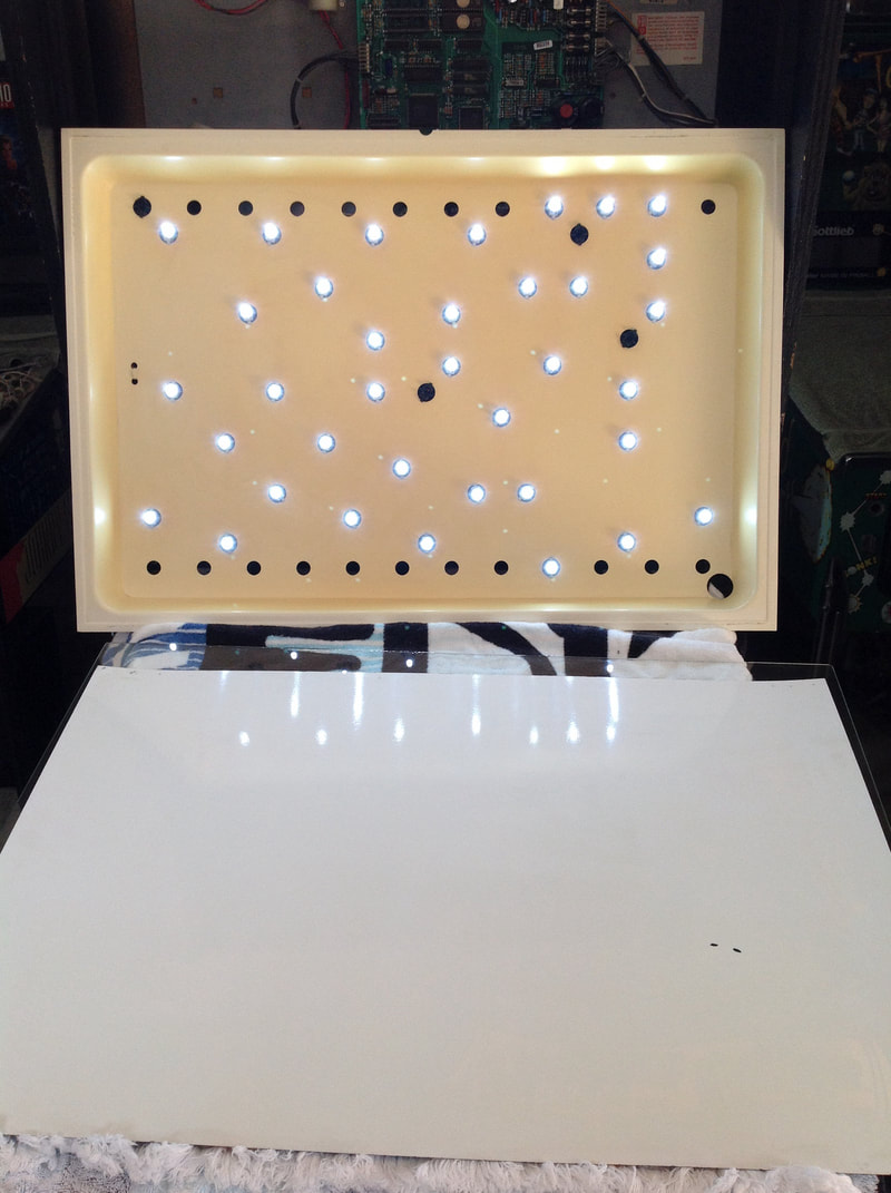
And the one final step was to replace the light panel lamps with LEDs instead of incandescents. This will brighten the backbox up nicely, generate far less heat, and consume much less power. All good reasons to upgrade to LEDs! Once this was all done, I was able to turn the game on, saw every single GI lamp working, and breathed a huge sigh of relief. It was a lot of work to fix all of the previous hacks, but the lamps are now bulletproofed for the future.

New LEDs installed in the backbox light panel.
Power driver board GI section now fully rebuilt.


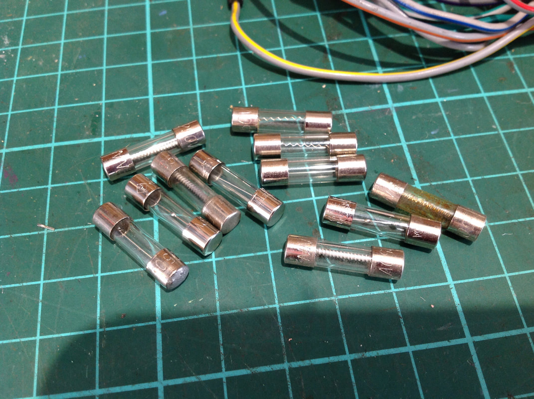
All of the incorrectly rated fuses removed from the power driver board.
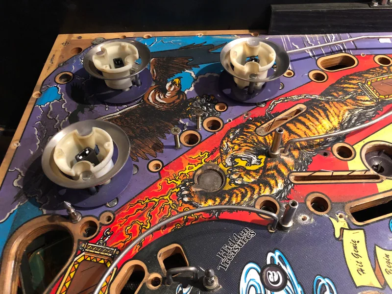
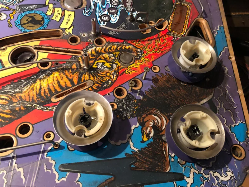
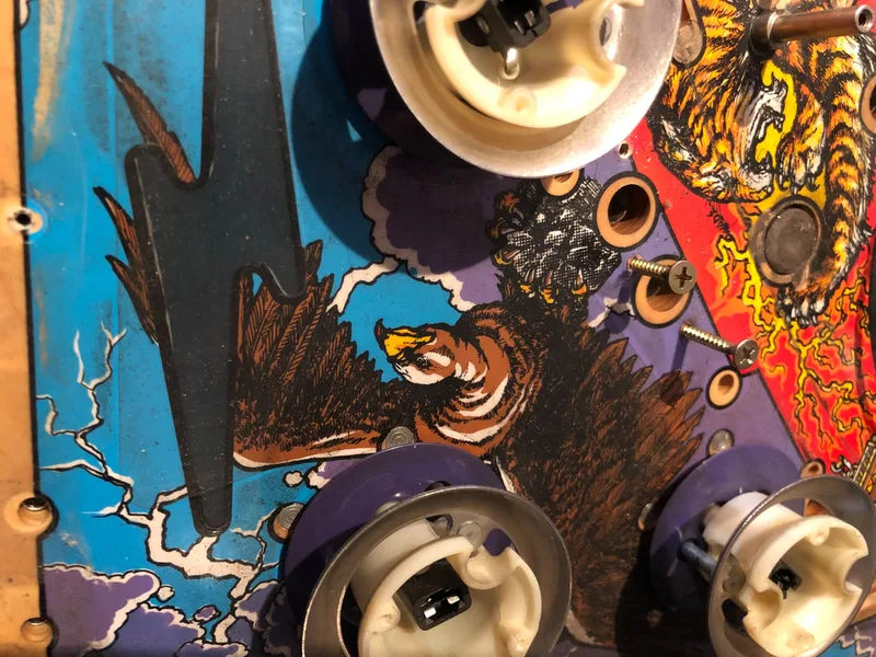
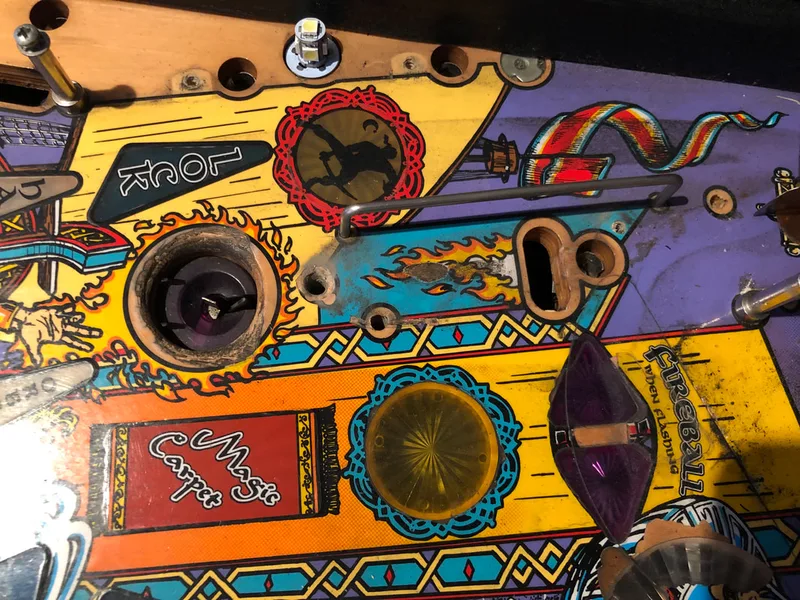
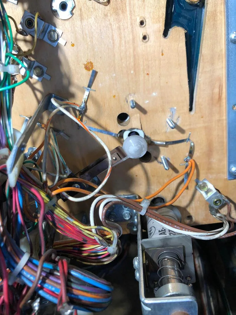
View of one of the pop bumpers showing the hole in the body.


Broken rod and ring assembly under the playfield.
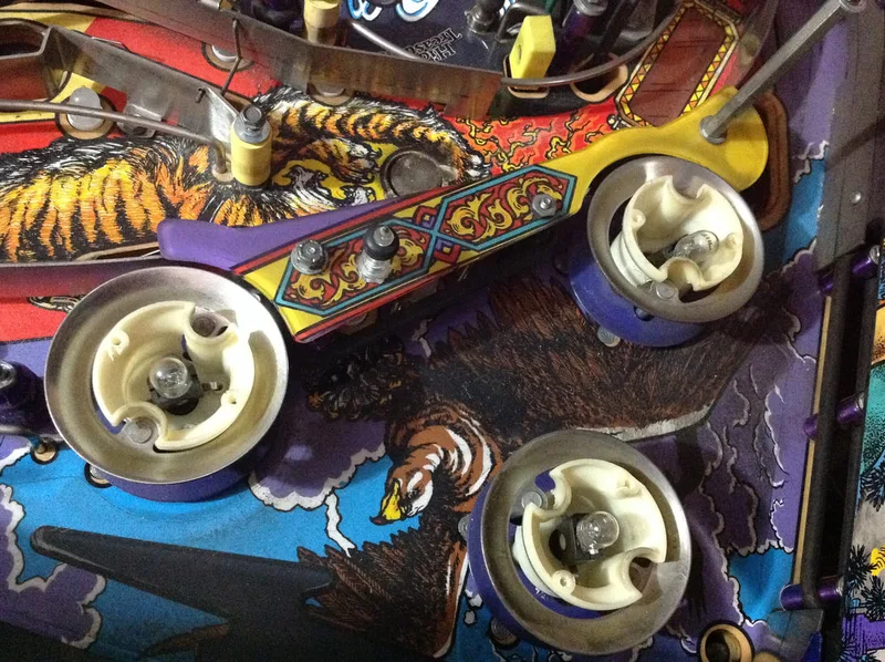
The rebuilds were relatively easy, but time consuming. The pain with WPC pop bumpers is that the lamp sockets are soldered in place, so they need to be cut and then resoldered once everything has been put back together. Make sure you take good photos of the assemblies underneath the playfield and the lamp wiring so you can connect it correctly later.

Pop bumper assemblies underneath the playfield.
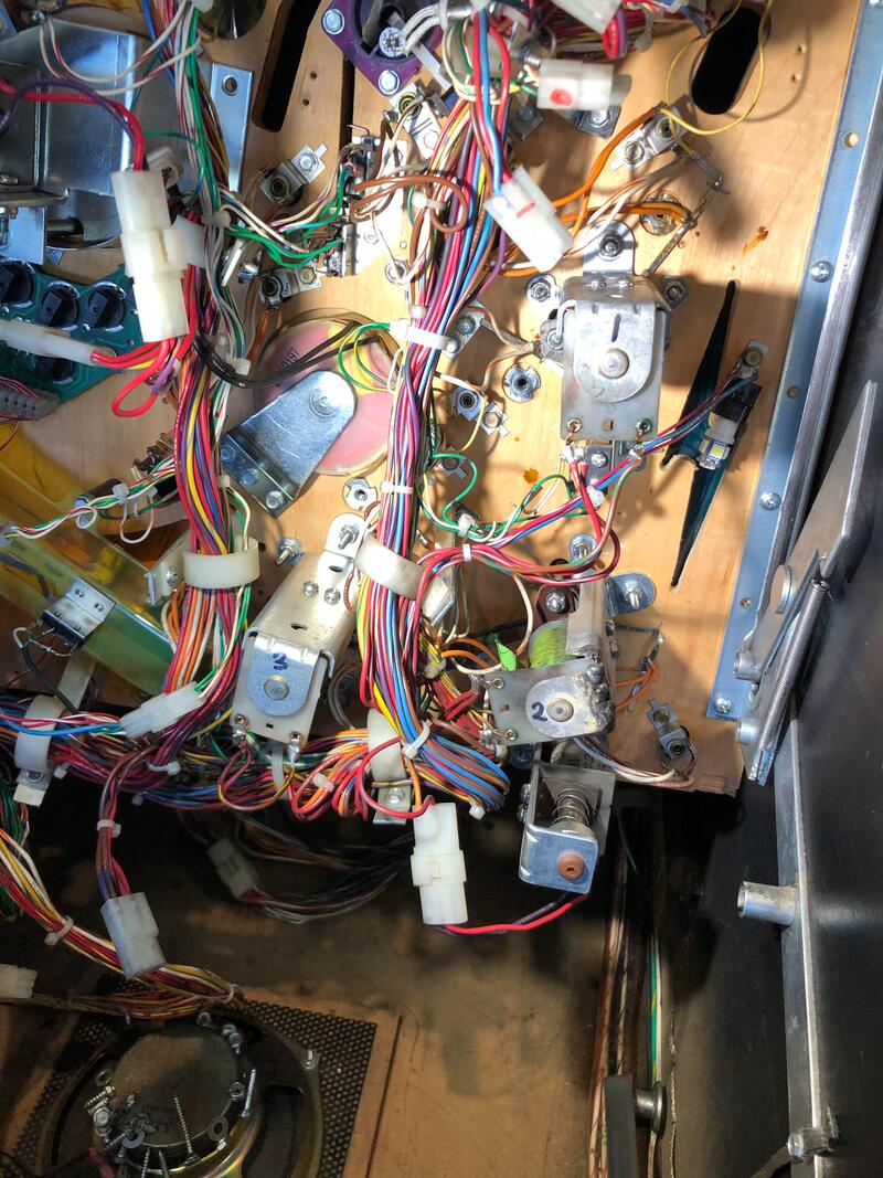
Example of pop bumper lamp wiring.
All of the pop bumpers required new metal yokes (RTBB, PSPA, Mr Pinball), new bumper bodies (PSPA, RTBB), and one required a new rod and ring assembly (RTBB, PSPA, Mr Pinball). Once all of those parts were installed, they were all good to go!

Just some of the broken parts removed.
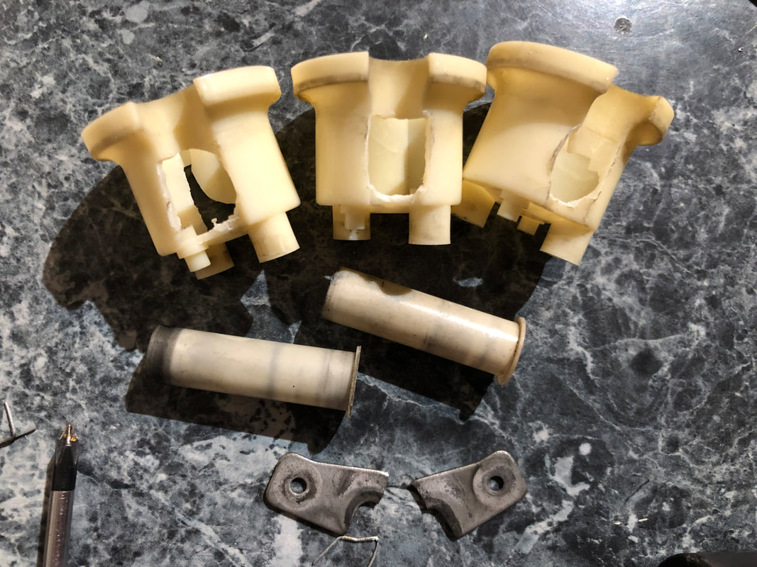

All rebuilt and looking good!
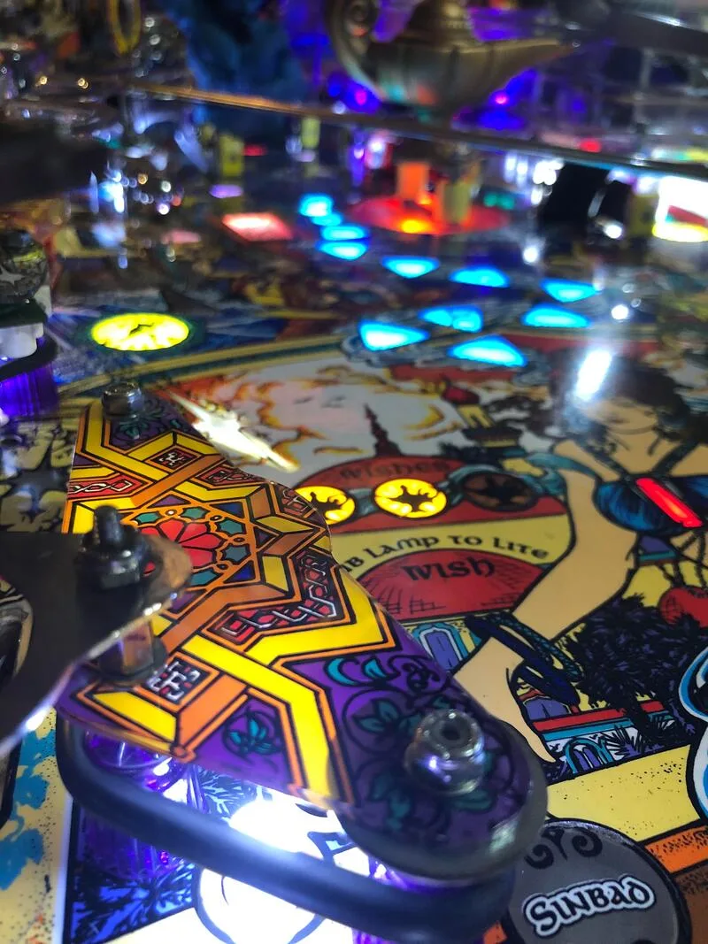
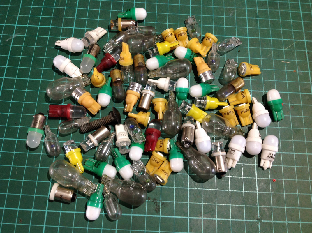
As soon as I took the playfield apart and removed all of the lamps, I realised why. Whoever had installed all of the LEDs must have been colourblind, and instead of colour-matching the LEDs with the inserts, they just stuck green ones everywhere. Plus some orange and red ones for good measure (surprise, surprise: the red and orange LEDs were not matched with red or orange inserts). There were a few white ones in the mix too, which worked fine where they were, but as most of the LEDs were different bulb types, there was a huge variation in the amount of light that they threw out.
The topside of the playfield was only slightly better. The majority of the general illumination lamps were white (yay!) but most of them were also single SMD LEDs with no dome, and pointed straight upwards (boo!). These types of LEDs are useless in GI applications because they only throw light upwards instead of outwards. General illumination is meant to light up the playfield, not the playfield glass. To add insult to injury, none of the flashers had been replaced with LEDs, either. I think whoever installed the LEDs on this machine really did a lazy job.

Insert LEDs after removal.
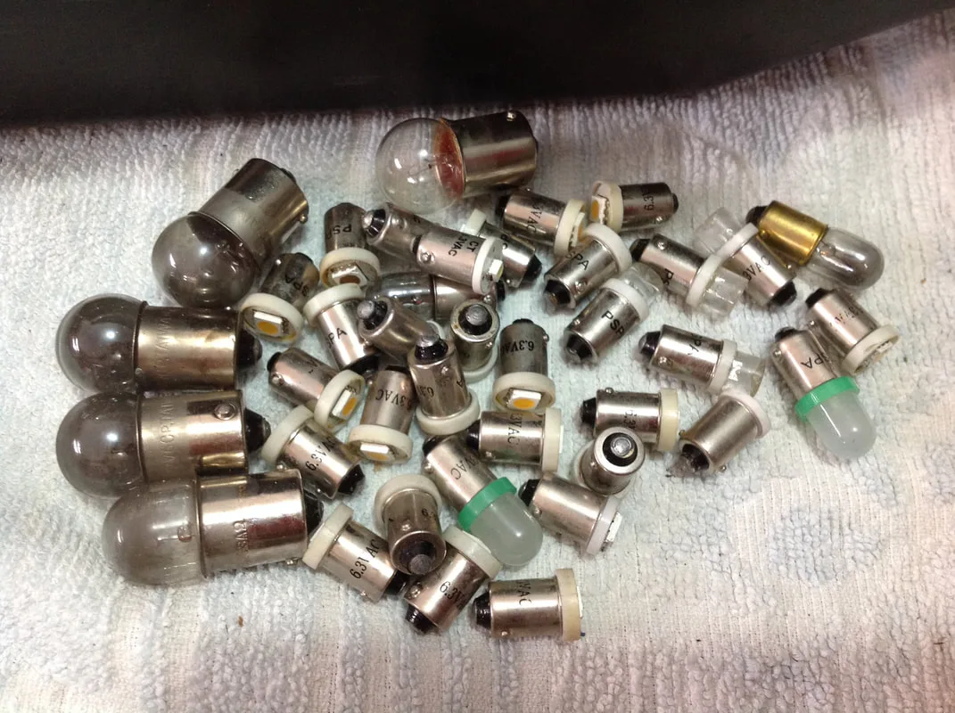
General illumination lamps after removal.

Thankfully, this issue was easy to fix. All of the insert lamps were replaced with white, single SMD LEDs which lit up the inserts evenly and thoroughly. For the topside of the playfield, I used cool, frosted white LEDs to make sure the light was thrown evenly around the sides of the lamps as well as up. This lit up the plastics and playfield much better than the original LEDs. And, of course, I installed LED flashers where needed. Tales of the Arabian Nights has a beautiful playfield with lots of colour in it, so in my opinion, you should not stuff around with too many different LED colours as it will detract from the original artwork. The exception is if you colour match every single insert, which will actually enhance them. Otherwise, white is a great colour to use everywhere.

White, single SMD LEDs under the playfield with frosted white LEDs in the general illumination.
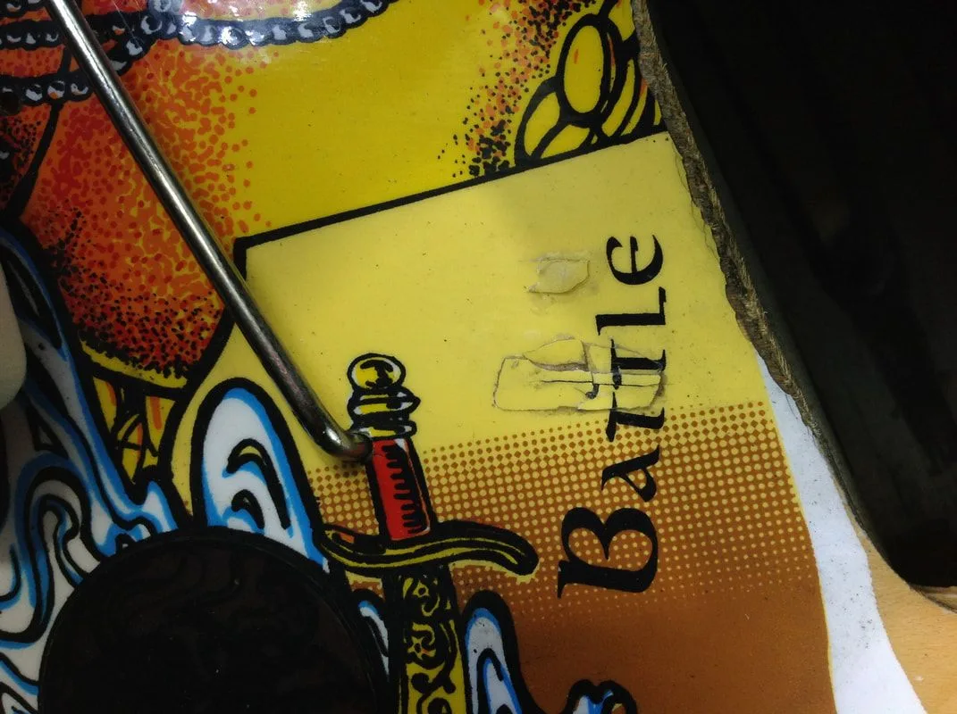
Now, onto some of the more innocent problems. The Final Battle flasher (between flippers) would not work. This was simply a wire (black/red) which had come loose from the socket. Soldering it back on fixed it up.
Loose wire for the Final Battle flasher.

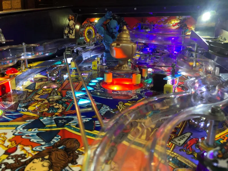
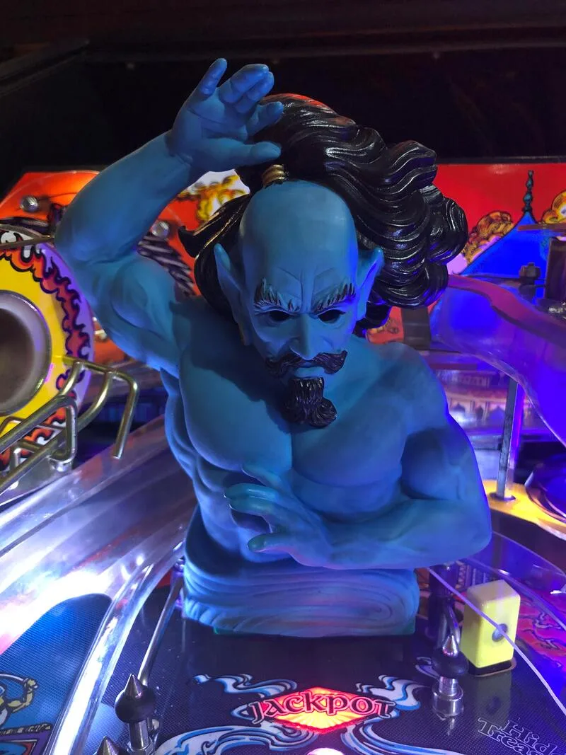
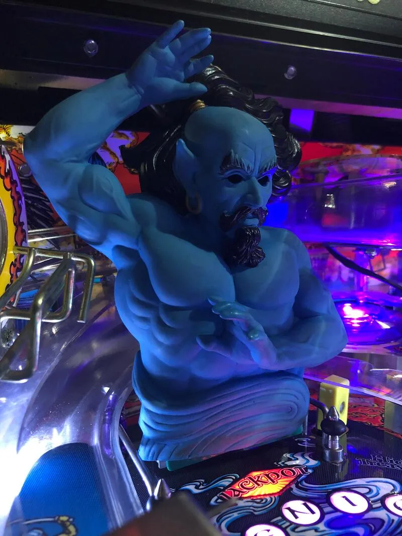
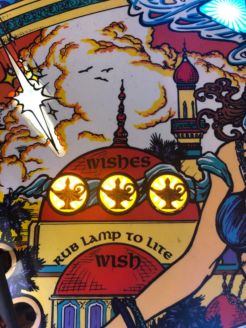
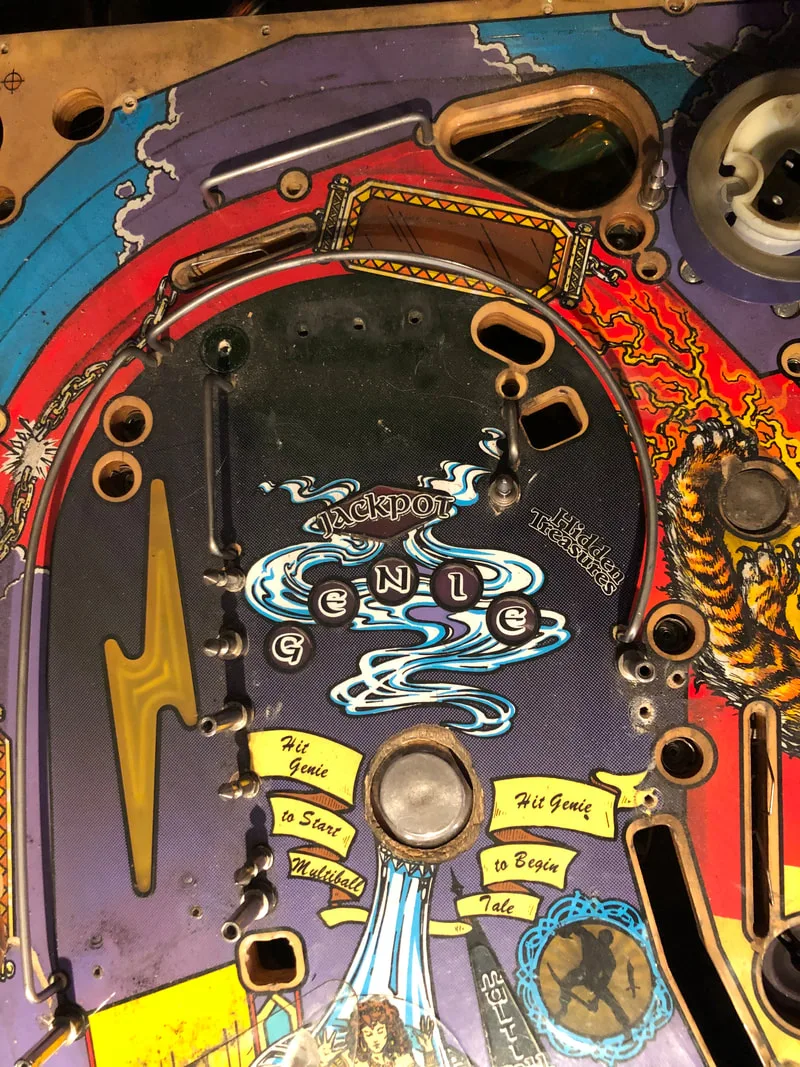
Some people don't actually realise that there is a flasher inside the genie's head on the playfield. This flasher is connected to the top loop flasher, and flashes in sync with it. So, if you don't fully disassemble the genie during your teardown, you might forget to replace this flasher, which is often broken. It was originally a red incandescent globe, but replace it with an LED as it is a pain to get to. The socket for this lamp was actually a little loose (i.e. the original globe was loose in the socket), but as the LEDs have thicker wedge bases, the new LED fit in the socket snugly.

The naked genie, showing the flasher inside the head.
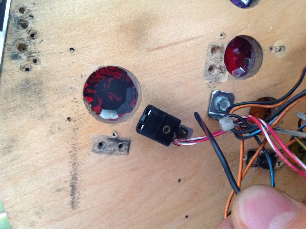
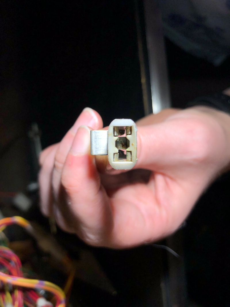
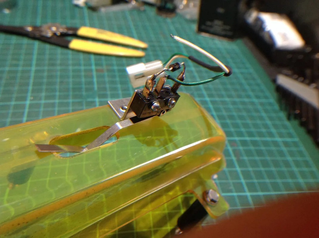
Another flasher socket was a problem - the left loop flasher under the playfield. This one would not light up, but during testing I found that wiggling the LED around would get it to light up intermittently. The lamp was very loose inside the flasher socket, so it appeared that the socket had just worn out. Looking at the socket from the top, I could see that the terminals were fatigued and had lost tension; they were no longer gripping onto the base of the lamp. I get the feeling that this had been a problem previously, and somebody had used some kind of glue on the socket, as it was covered in a sticky residue. There's no sense trying to save these sockets; just replace them (Mr Pinball, PSPA).
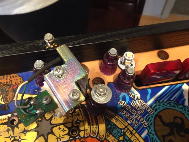
Left loop flasher socket covered in sticky residue.

Flasher socket with fatigued terminals that have lost tension.
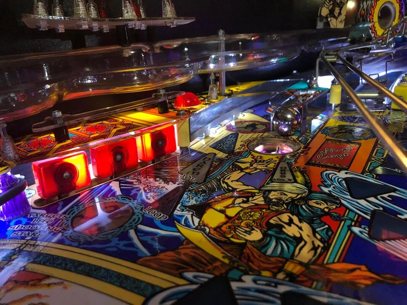
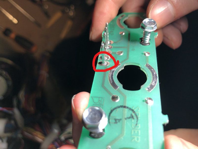
The next issue was related to a series of smoke lamps (the blue, triangular inserts that snake their way down the middle of the playfield). Most of these lamps are lit by a series of lamp boards under the playfield. One single lamp on a three-lamp board was giving me issues by either lighting up dimly, or not lighting up at all. Lamp boards are always problematic due to the lamp sockets themselves, the socket solder pads, or the header pins, as described on Pinwiki. The header pins were the problem in this case, with one pin having cracked solder at its base. Reflowing the solder was all that was required.
Cracked solder joint on a playfield lamp board.
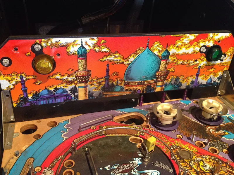
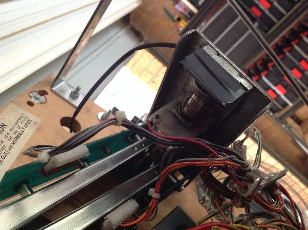
The final lamp issue was a trickier one. It involved three flashers - the left eject flashers (2) and a flasher in the top left corner of the backbox. The backbox flasher is wired to the eject flashers, and fires in sync with them. The flashers actually worked, but the problem was that they worked even when they shouldn't. Whenever a flipper or other playfield coil fired, all three flashers would activate briefly. It wasn't overly noticeable, but you would see it if you were watching the game.
The interesting thing was that this problem disappeared when incandescent globes were put back into the affected flasher sockets. So this was therefore a problem of some minor amount of current on the solenoid circuit which was causing LEDs to light. However, there was not quite enough power to drive an incandescent filament. This is one drawback of LEDs - they are much more sensitive to electrical noise than incandescent globes are. This current leakage is harmless, and won't damage the LEDs at all. If you wish to fix it, I found a topic on Pinside which related to another WPC-95 game, Scared Stiff (Williams, 1996), which suggested installing blocking diodes across the flasher socket. I didn't try this solution myself, but the theory behind it seems sound.
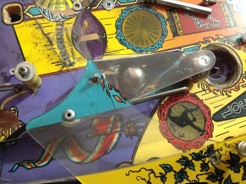
Broken scimitar plastic above left flipper.

Broken plastic to right of bazaar scoop.
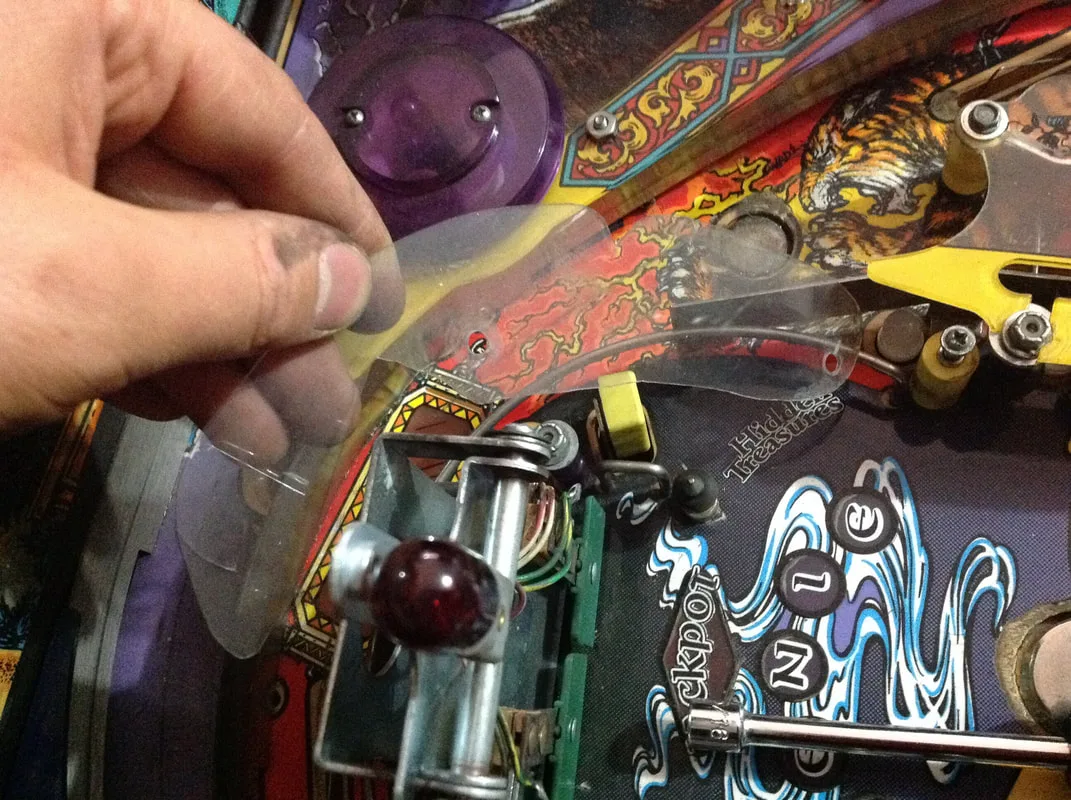
Custom-cut acrylic piece to replace plastic behind genie.


Cracked and broken plastic above ball lock.

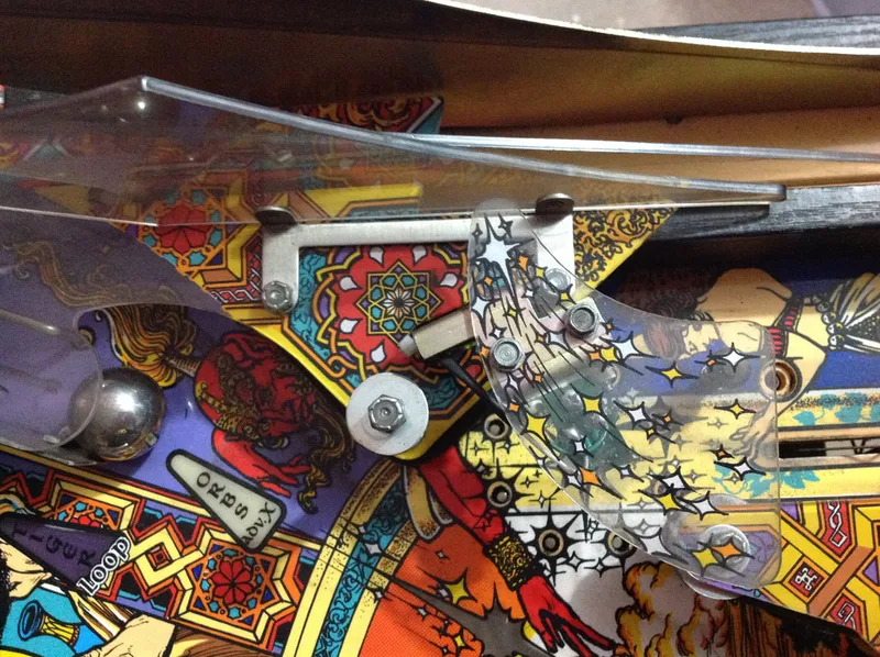
One plastic in particular had been repaired quite impressively. It was the plastic that covers the captive ball on the left of the playfield. This one had snapped, probably due to balls striking the captive ball and then smashing into the plastic. However, it had been repaired by someone riveting a slingshot protector plastic in place of the broken section. It actually covered more or less the same area as the original plastic - it was actually the perfect shape!

Repaired plastic above left captive ball.

Reverse side, showing repair work.

Luckily, full plastic sets as reproductions from Planetary Pinball and are available locally (RTBB). Various individual pieces are also available on their own (Pinball Center). An entirely new plastic set was out of the budget set for this restoration, but luckily, some NOS plastics were available locally for a reasonable price including the scimitar above the left flipper (part no. 31-2545-7, PSPA) and the plastic above the left captive ball (part no. 31-2545-1, PSPA).

New plastic installed above left captive ball.

New plastic installed above left flipper.
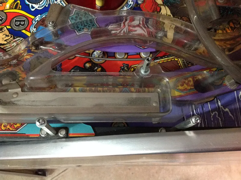
One plastic that also constantly breaks is the ramp plastic, located to the right of the ramp entrance. This is a long, thin plastic which covers the posts in this area. This plastic breaks so often, that most games do not have it, and as far as playfield plastics go, it is quite pointless. It is a clear plastic with no graphics printed onto it, and it does not serve much of a purpose in terms of preventing ball hang-ups. Balls cannot get stuck on these posts, so a plastic here is unnecessary. If you do want to replace this plastic, they are available to purchase (Pinball Center) and more durable metal replacements are available from Pinside user Robertstone0407.
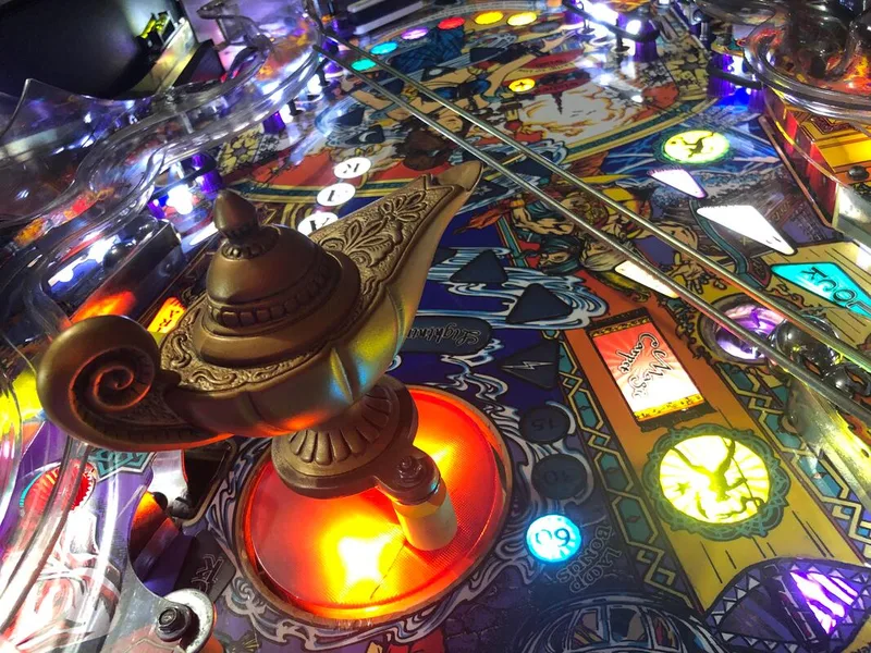
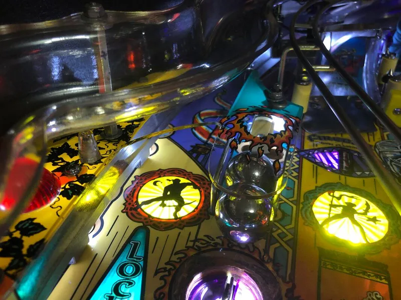
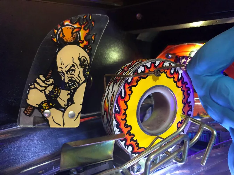
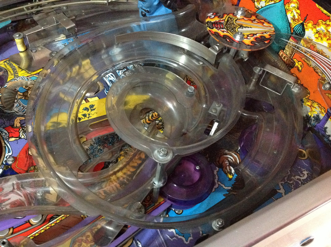
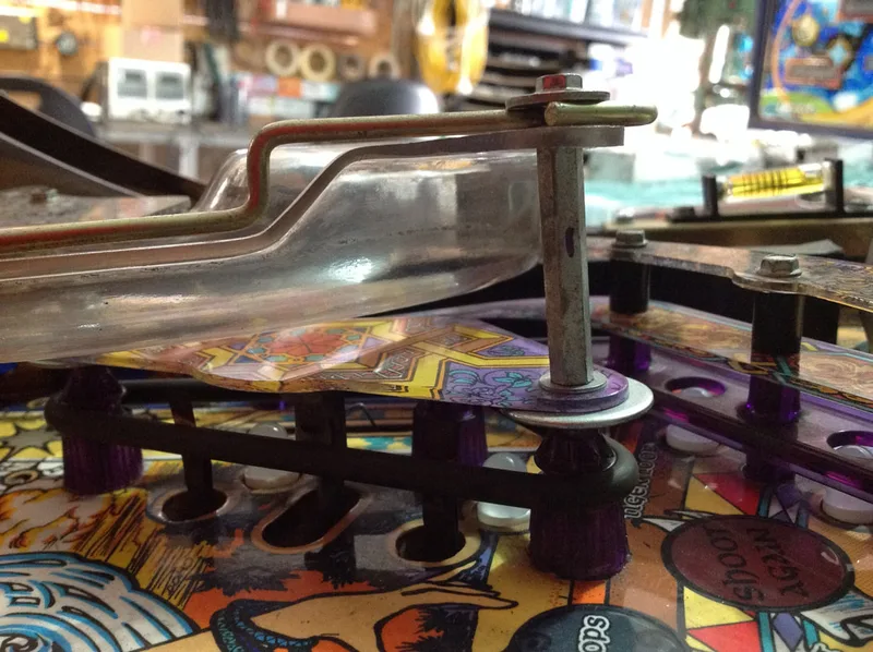
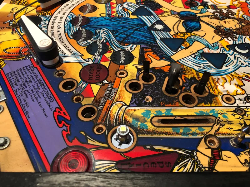
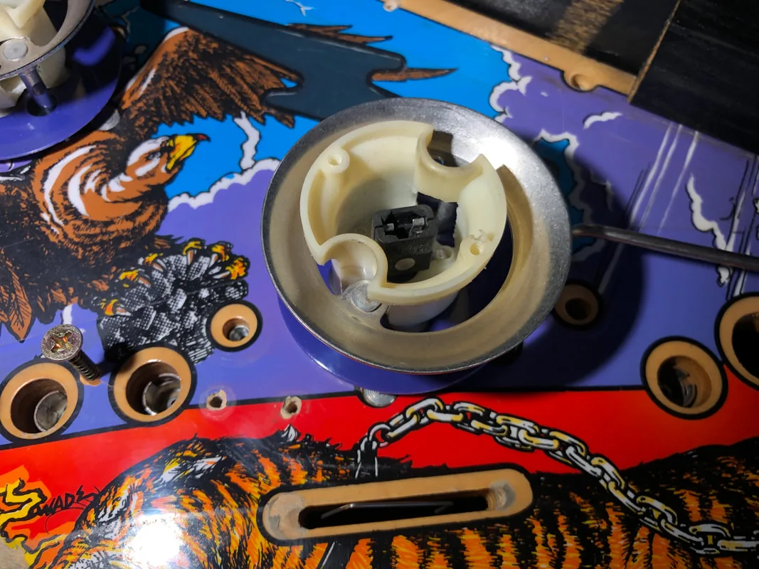
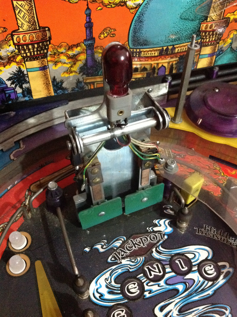
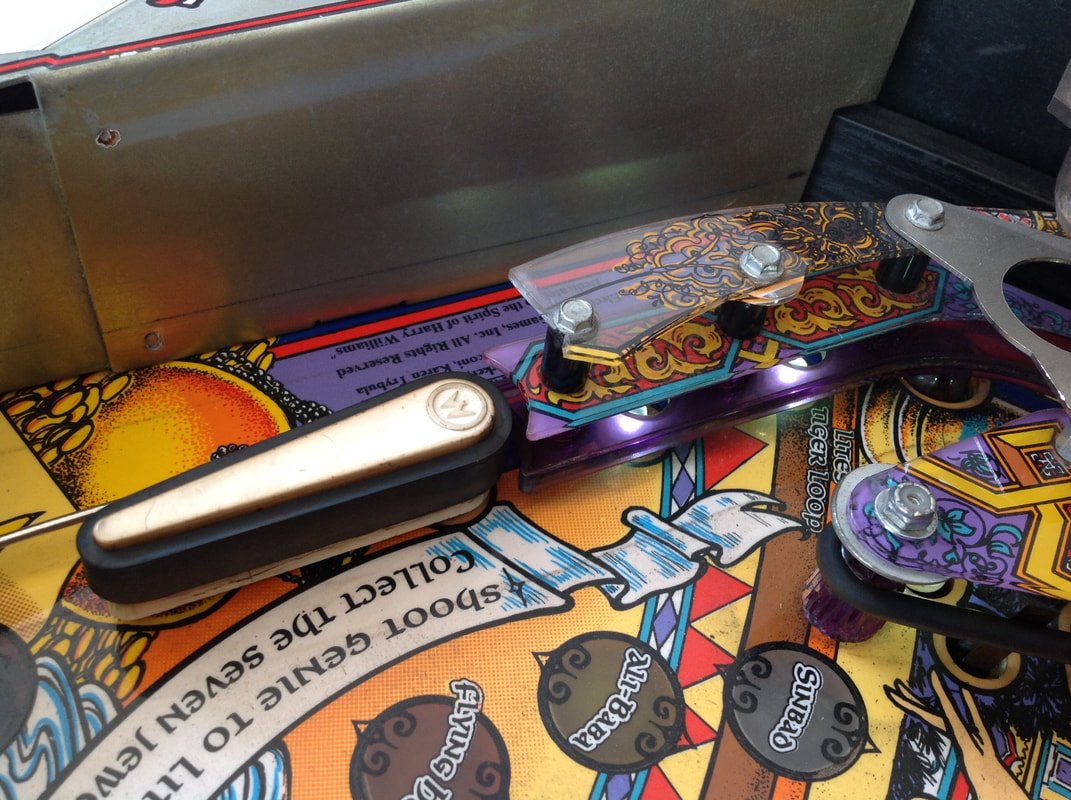
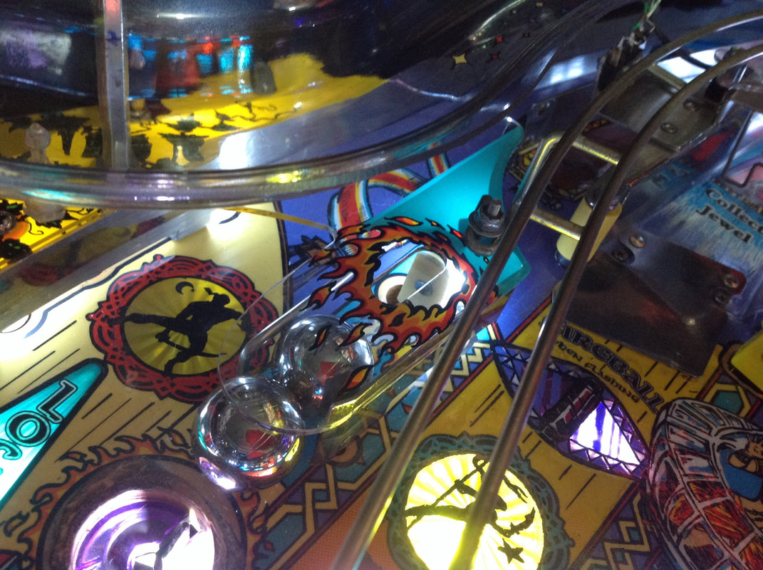
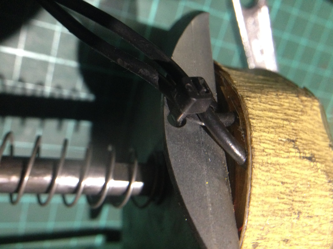
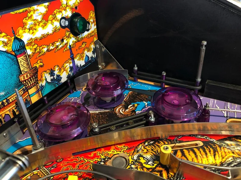
The main issue with this lamp was that it did not spin nicely. When struck, it would spin a little, but if it was hit with any force (which should make the lamp spin fiercely), it would instead start to shudder, and then grind to a halt. The first step was to take the assembly apart, and give it a good clean.
Once it was clean, it still didn't quite spin as nicely as it could. I noticed that there was some slop in the assembly where the lamp could move up and down (vertically) which was contributing to vibration and shuddering which was robbing it of speed. To stop this, I installed an extra washer, which shored up the assembly and kept everything nice and tight when it spun. Once I installed the washer, the shuddering stopped, and the lamp spun very nicely.
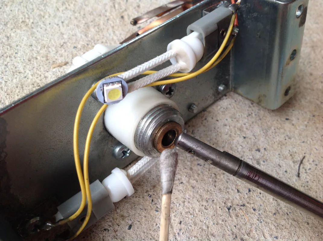
Using a cotton bud to clean the grease from the lamp shaft.

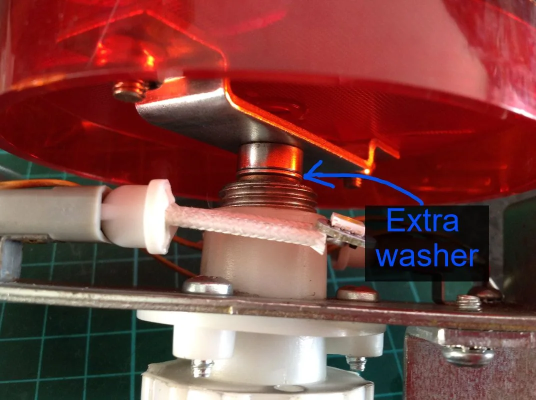
Location of the extra washer to reduce vibration and shuddering.

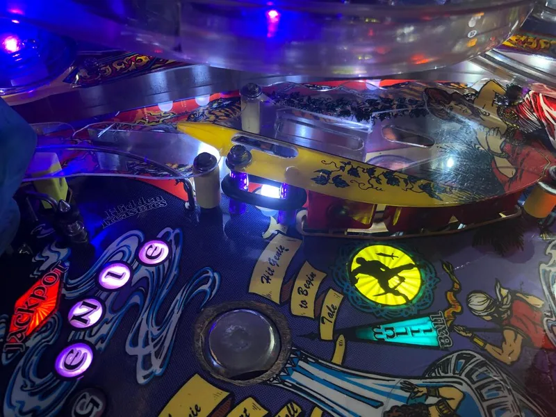
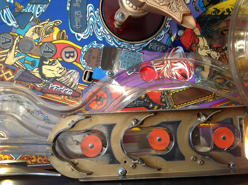
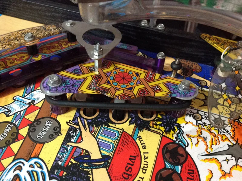
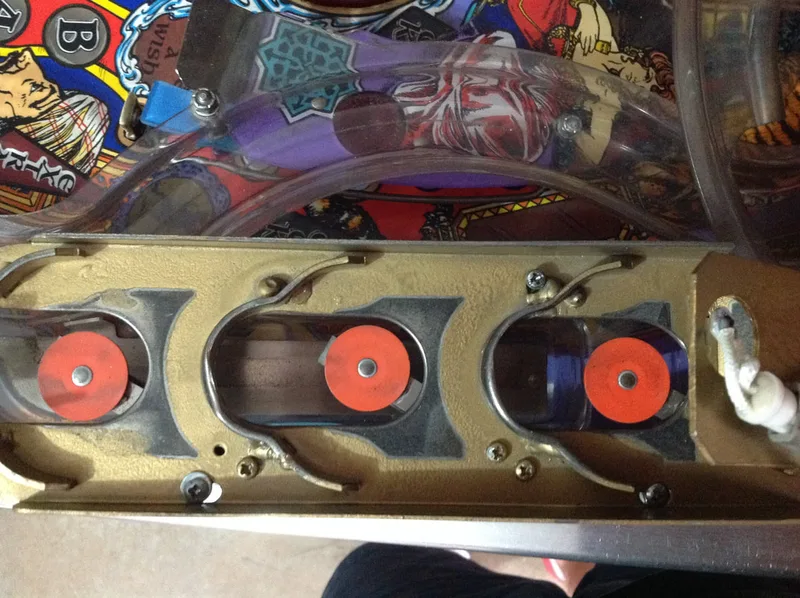
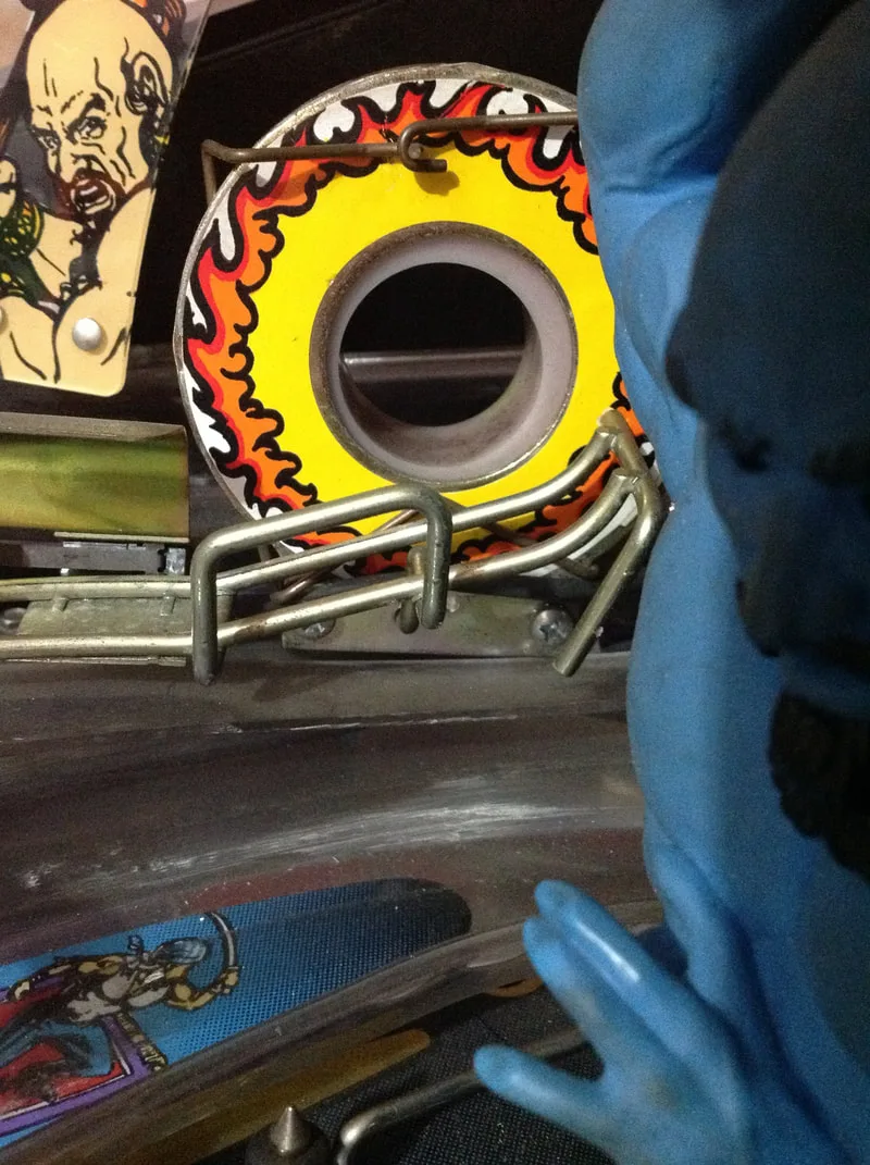
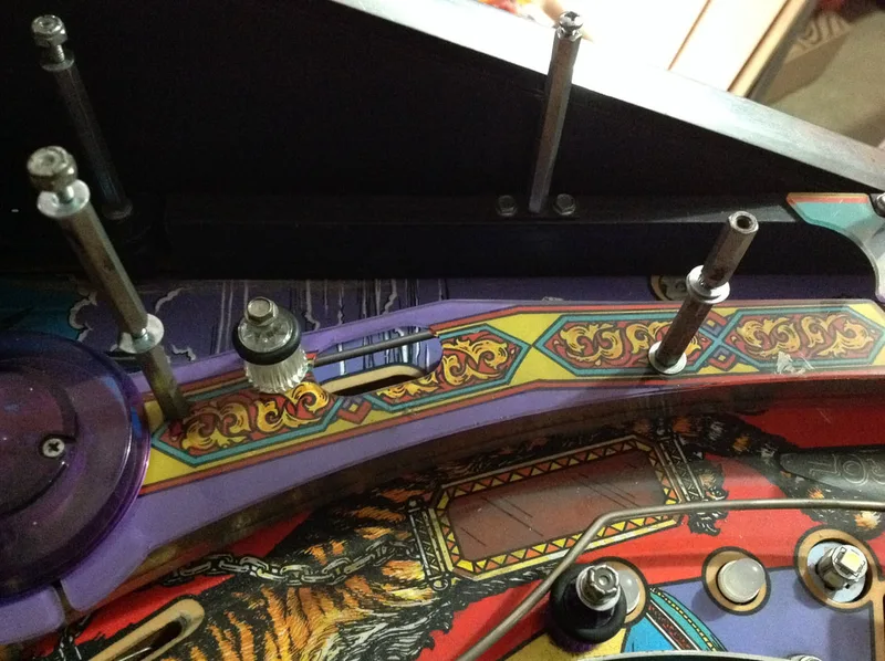
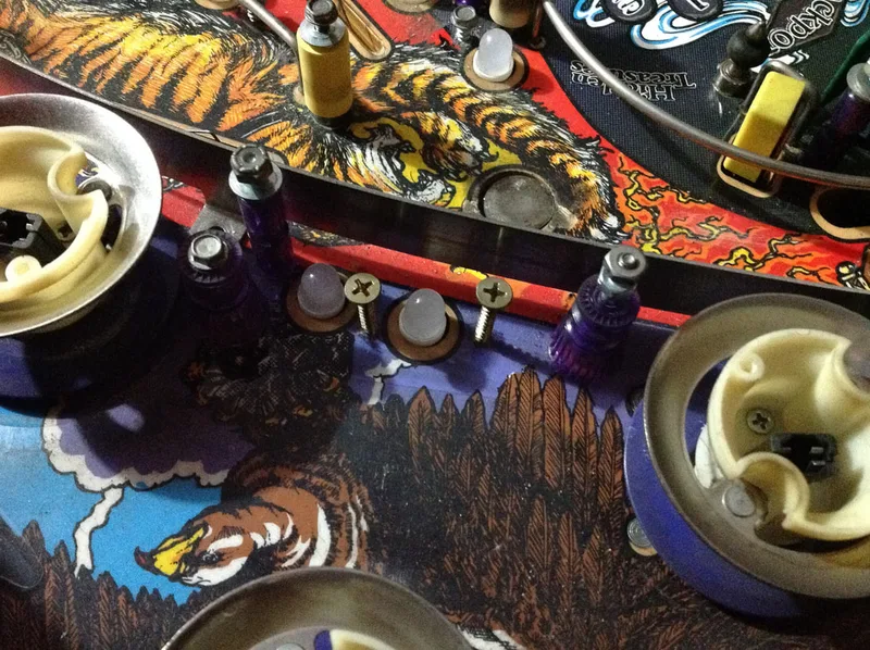
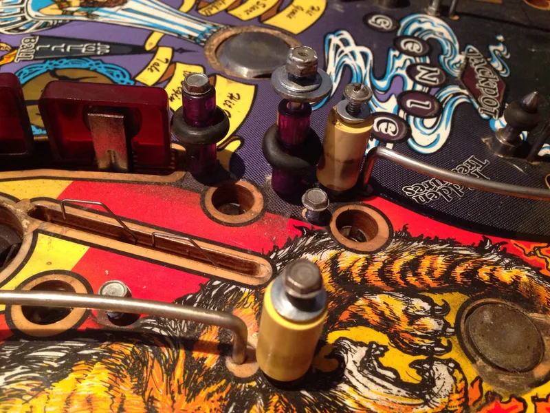
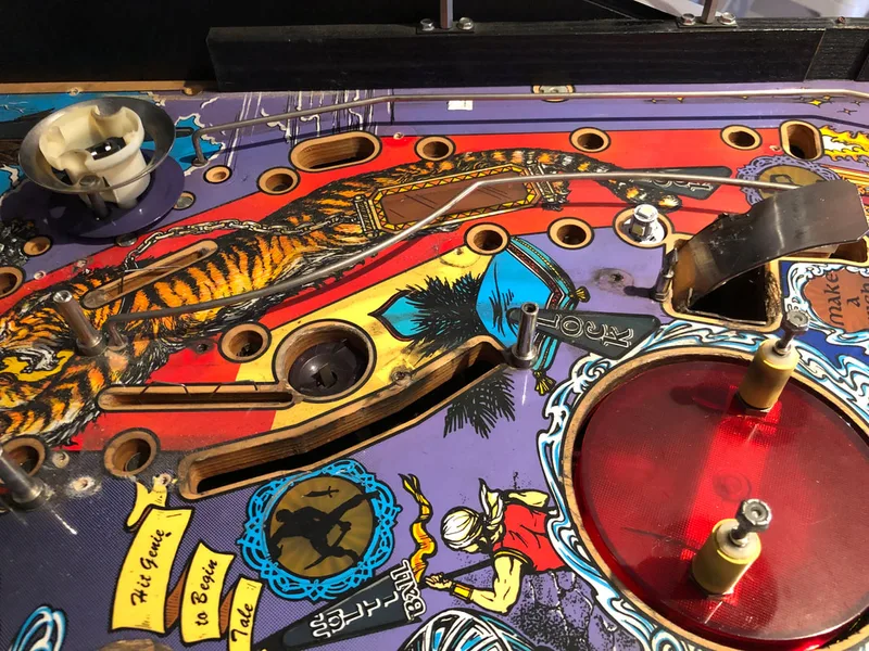
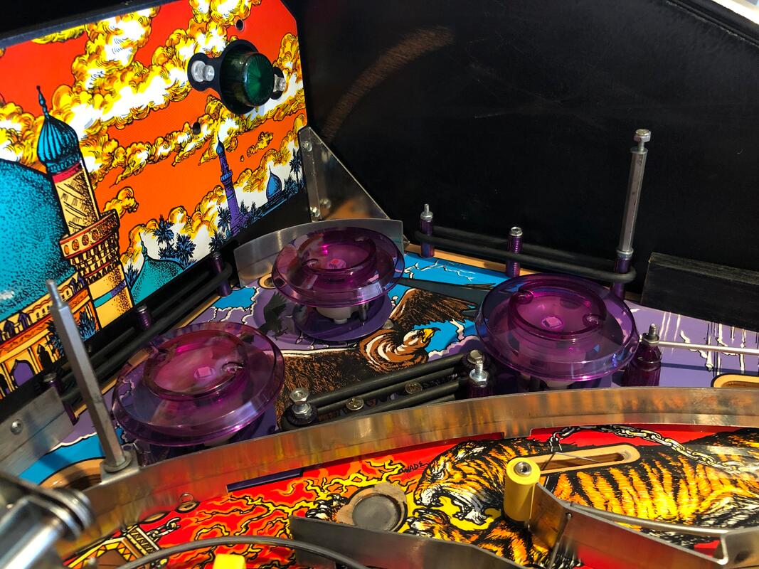
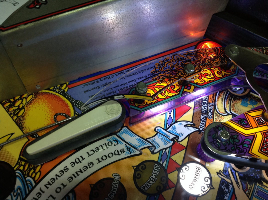
One often overlooked part of the lamp assembly are the rubber post sleeves. The ones that were installed on this game when we got it were regular yellow sleeves (part no. 23-6552). These are NOT the correct sleeves! The lamp actually uses much thicker sleeves with a 3/4" diameter (part no. 23-6770, RTBB, PSPA, Mr Pinball) which make the lamp easier to hit. Be warned - these sleeves are unique to Tales of the Arabian Nights, and they aren't cheap!
View of the regular rubber sleeves on the playfield and the correct diameter sleeves on the lamp assembly.

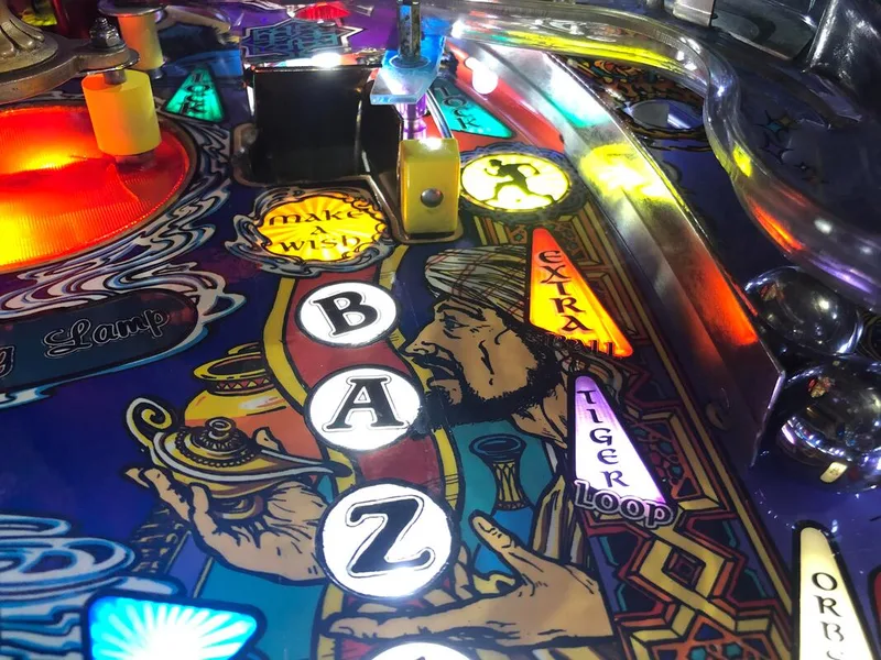
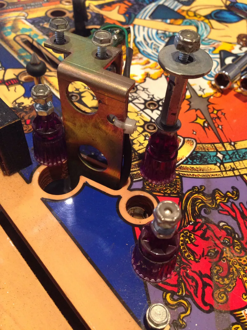
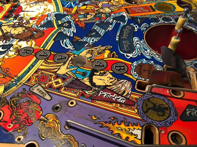
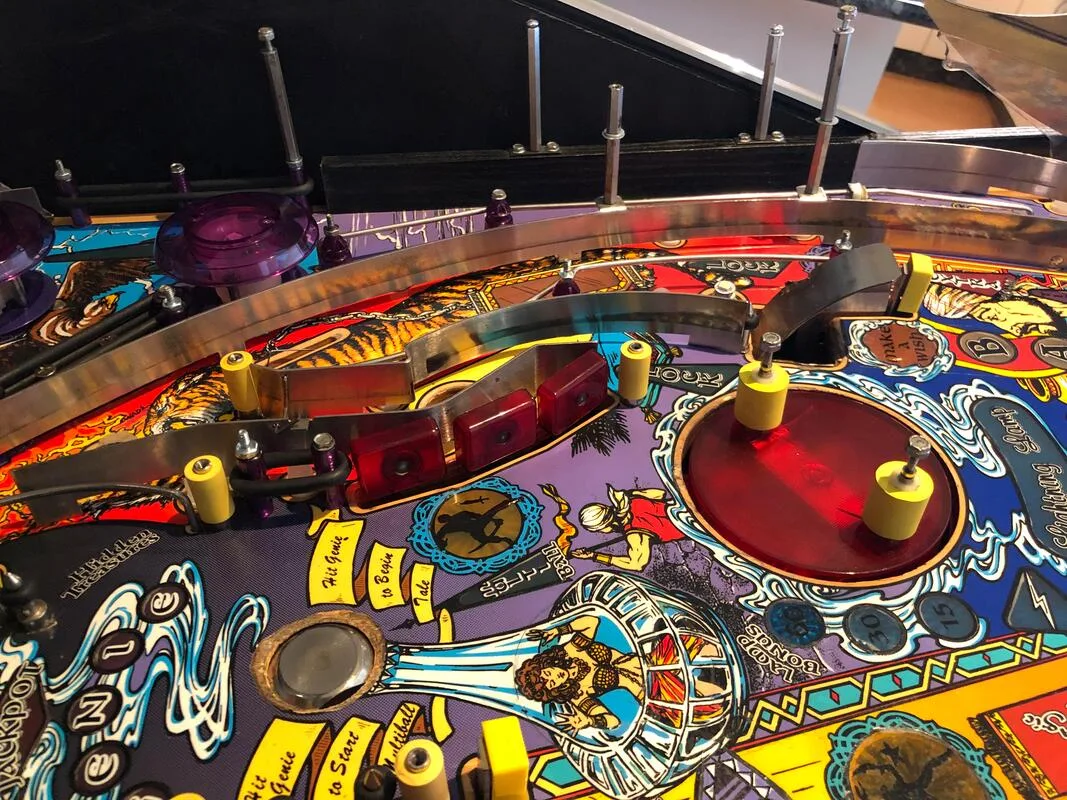
The issue on this game was the Bazaar and right captive ball targets. This game had both switches, but they were odd types for their locations. The targets on the playfield, which get direct ball impacts, are meant to be strong, oblong-shaped targets. Williams chose yellow mini targets for this purpose (part no. A-18017-6).
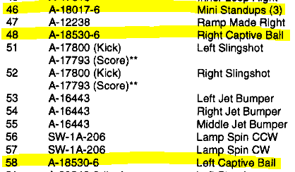
The Bazaar target on this game was a regular, flat standup target instead of the oblong mini target it should have been. However, there was a yellow mini target in the position of the right captive ball switch. The captive ball switch is actually meant to be an flat standup target (part no. A-18530-6).
Manual excerpt showing switch assembly numbers. Note that this incorrectly lists there being three mini standups on the playfield, when there are actually only two!
So, I had both of the switches I needed, but for some reason they were in opposite locations! The switches on the left side of the playfield were correct. I checked the switch wiring and they were indeed wired correctly. Maybe, at some point in the past, somebody had swapped them over to test something? I have no idea why they would be in the wrong spots otherwise. Either way, it was easy enough to swap them back to where they should be and swap the wires between them. While I was at it, I replaced the degraded backing pad of one of the switches.

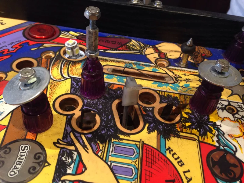
Standup targets in incorrect (swapped) positions.
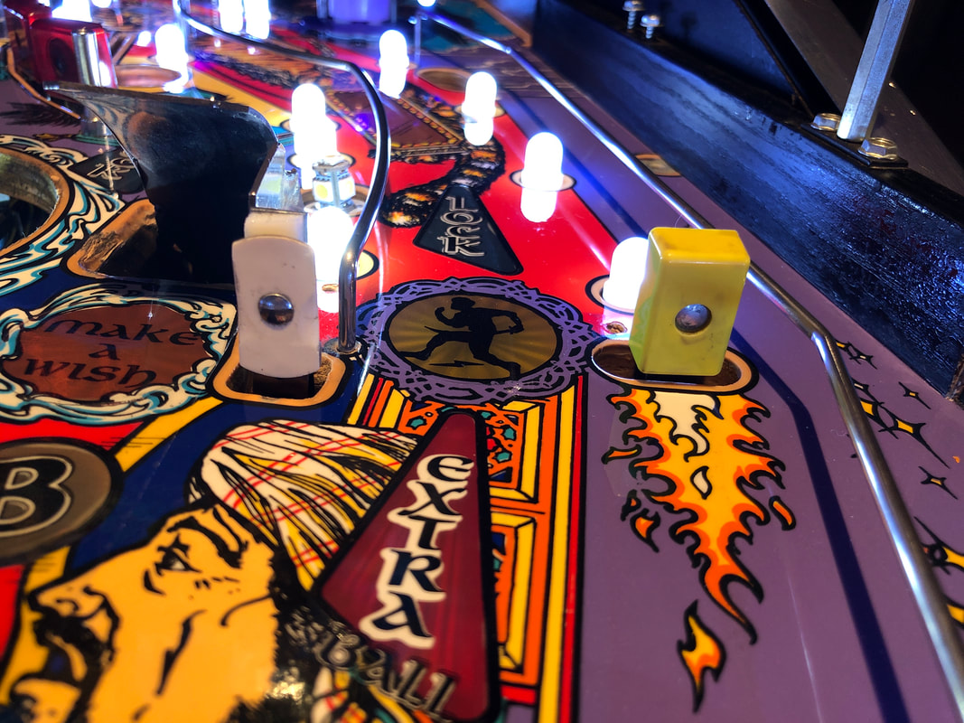

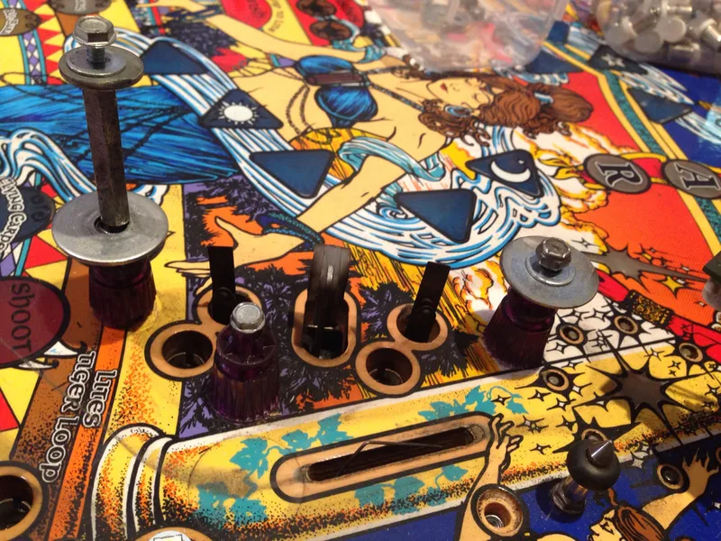
Standup targets now in correct positions.
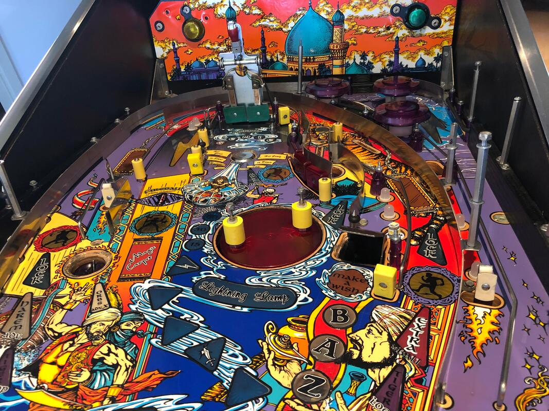
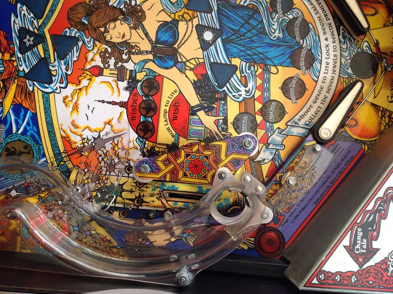
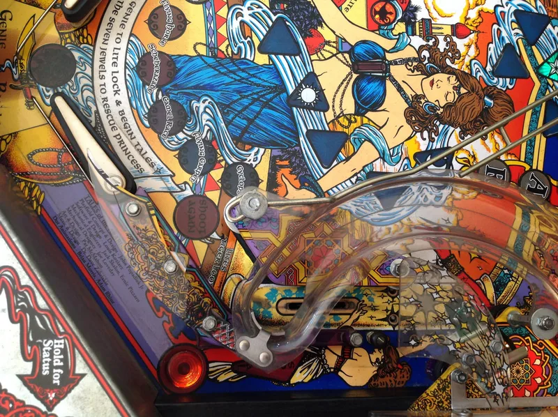
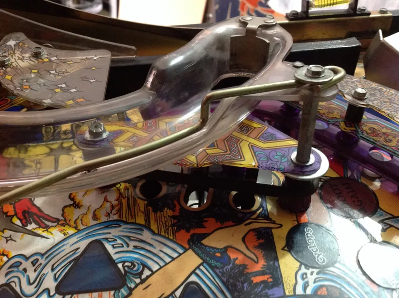
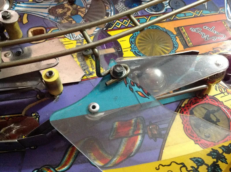
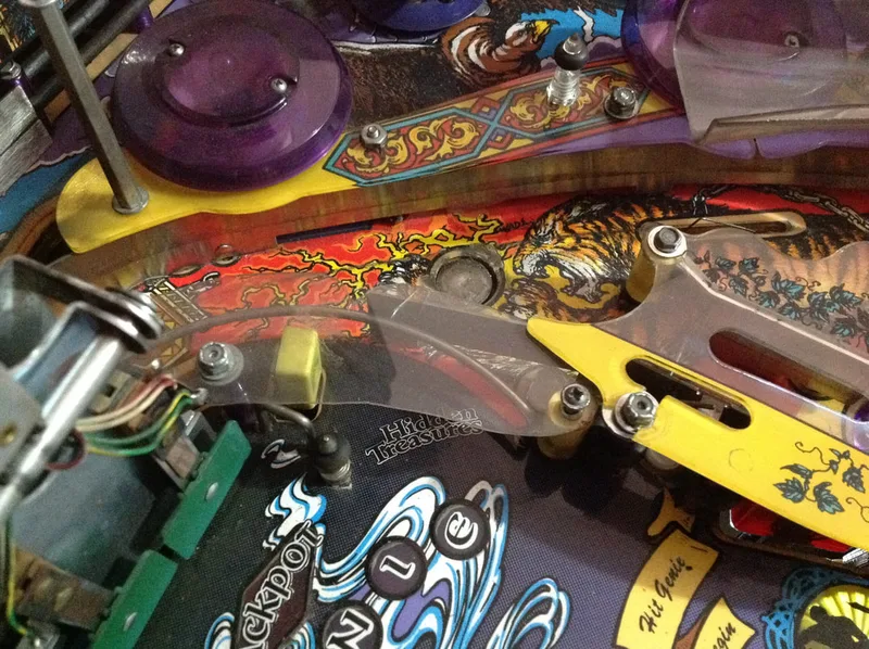
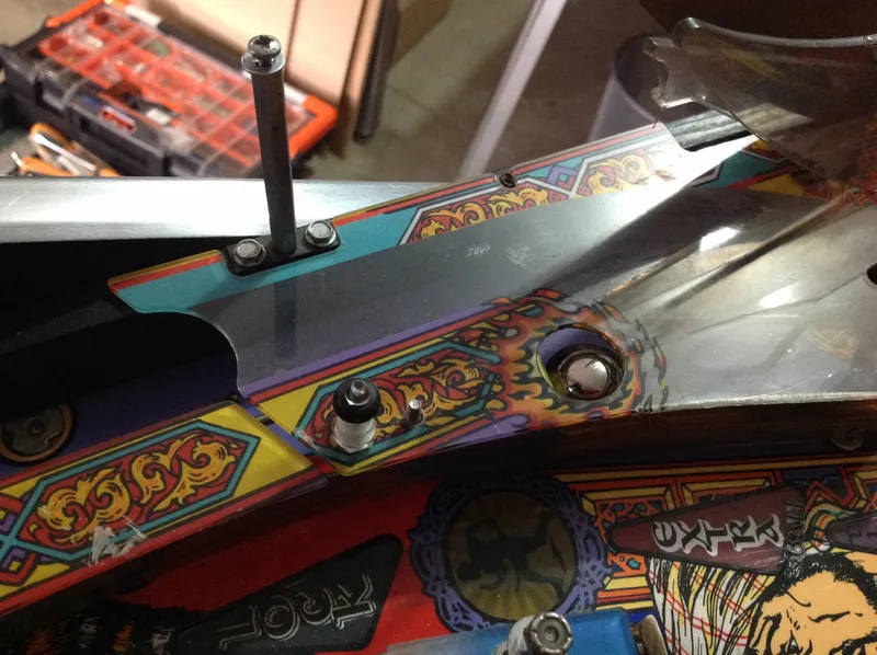
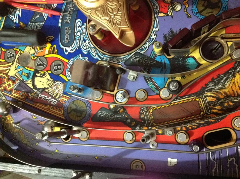
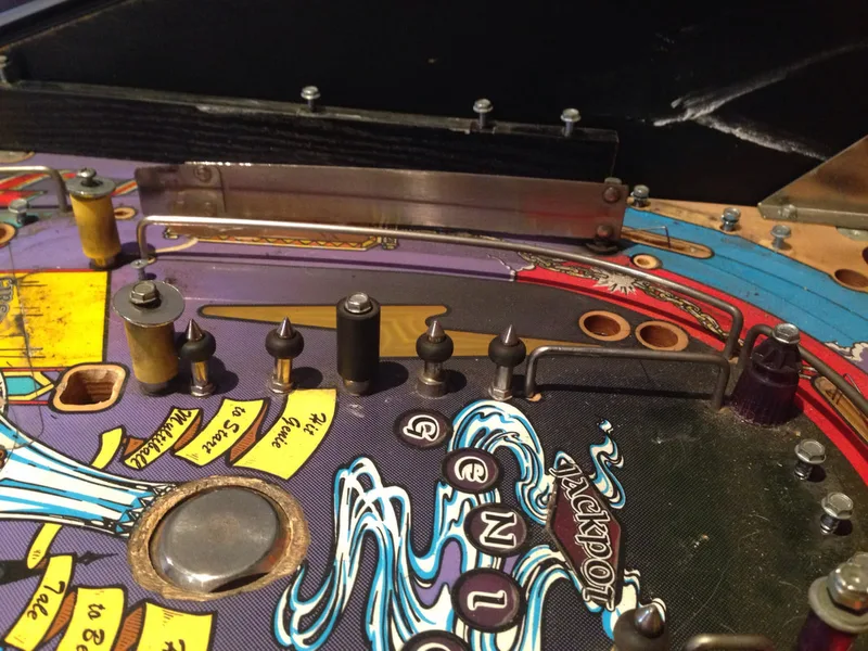
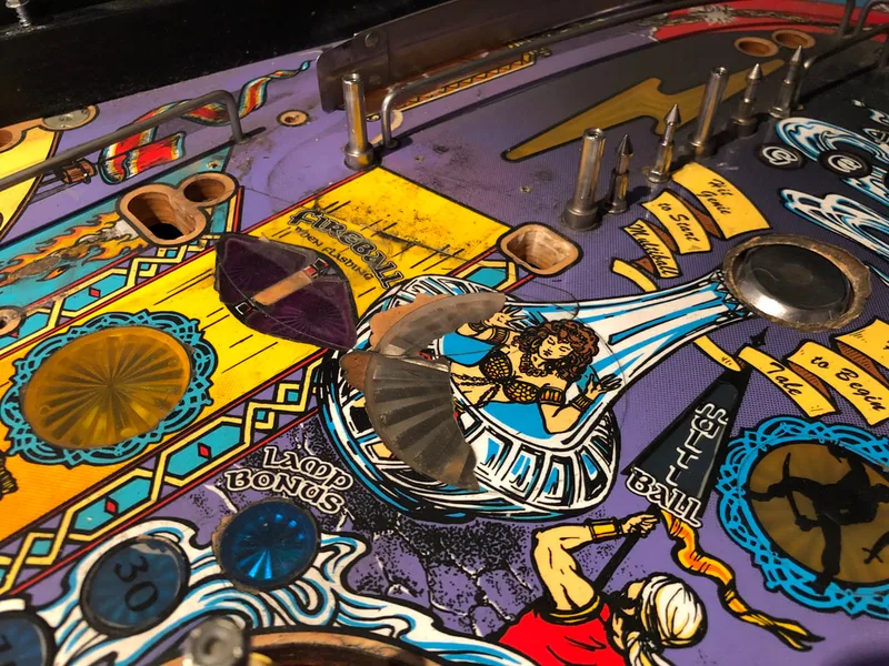
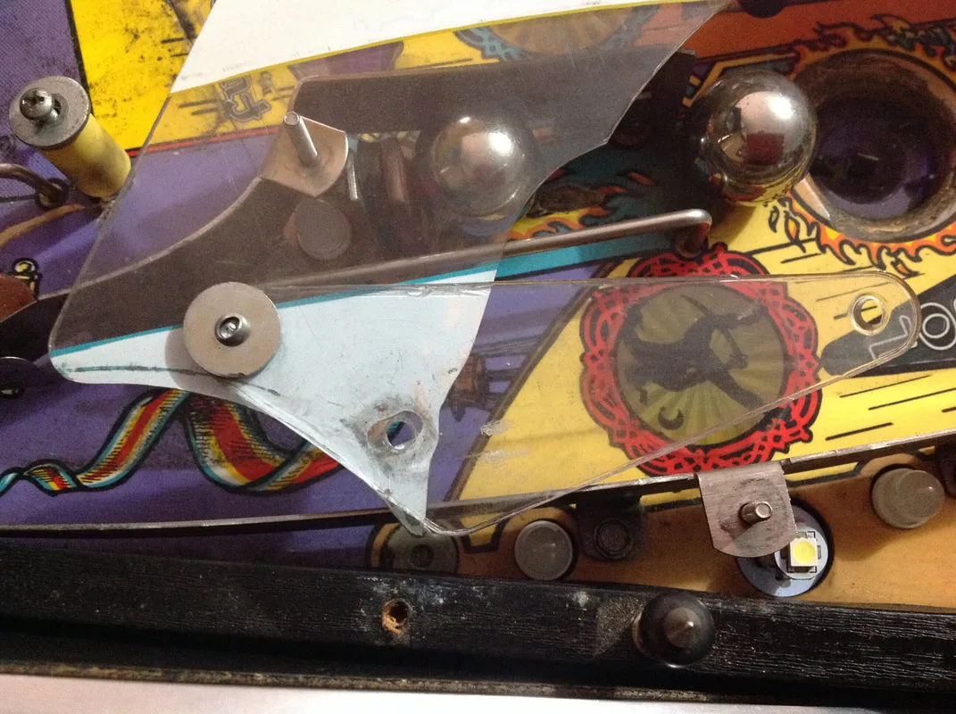
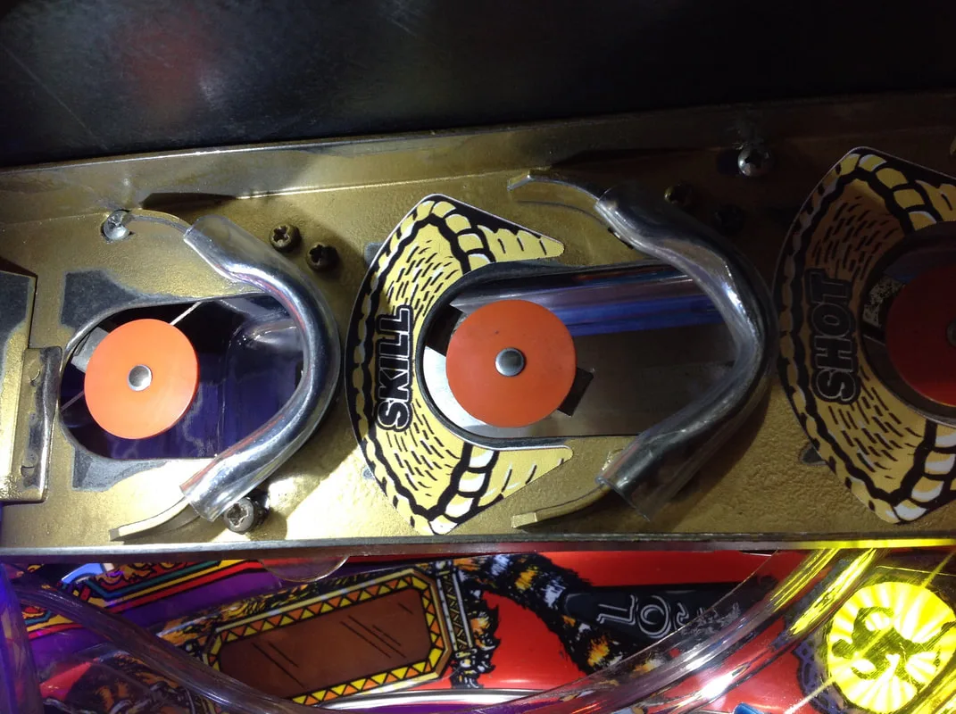
Note that the ball is NOT meant to ride along the edge of the scimitar blade like that! It's meant to sit in the "rut" between the metal blade assemblies before flying into one of the skill shot baskets.
This is why I love using slow motion to troubleshoot problems. Without the benefit of slow motion, the wacky movement of the ball was totally unnoticeable to the naked eye, and all you saw was the end result of the ball flying onto the playfield from weird angles. I originally thought the ball was hitting something as it was launched into the air, but once I reviewed the footage above it became clear that something was messing with the ball's path in the shooter lane, well before it went airborne.
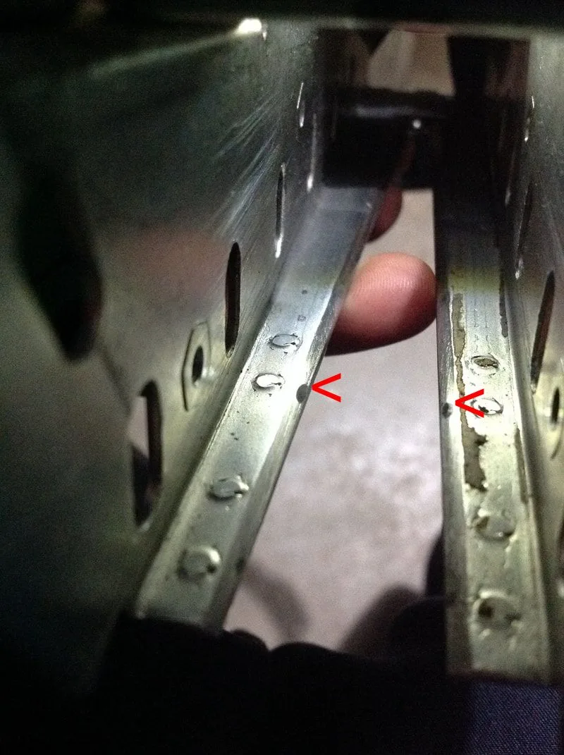
Normally, the ball is supposed to ride up the edge of the plastic that protrudes through the playfield (guide assembly, part no. A-20694). This plastic is the 'centre' blade of the scimitar blades that flank the shooter lane and frame the skill shot. The ball rides up this "guide rail" and is sent towards the skill shot baskets. I noticed that the ball started to move erratically when it first mounted this guide rail, so I had a closer look at it.
Turns out, the edge of the "guide rail" worn in such a way that the plastic had been chamfered on one edge. This had the effect of creating a slope which the ball bounced off, then hit the side of the cabinet, and then went all over the place. This is what was causing the ball to go every which way once it was in the air. The repair was simple - a bit of sandpaper to grind the plastic down to a nice, straight edge. That way, the ball hit the plastic squarely, and continued up the plastic edge rather than being diverted left or right.
Front view of the guide plastic with chamfered edge (arrowed).

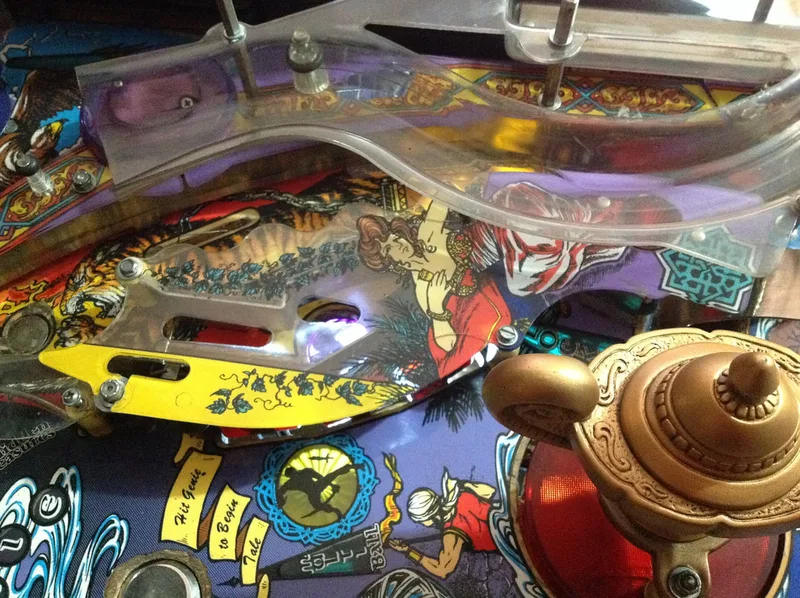
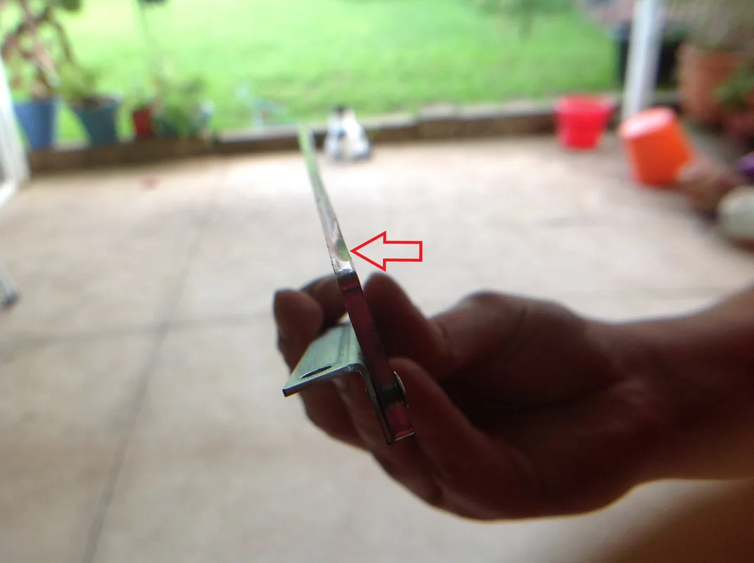
Side view of the chamfered plastic edge.
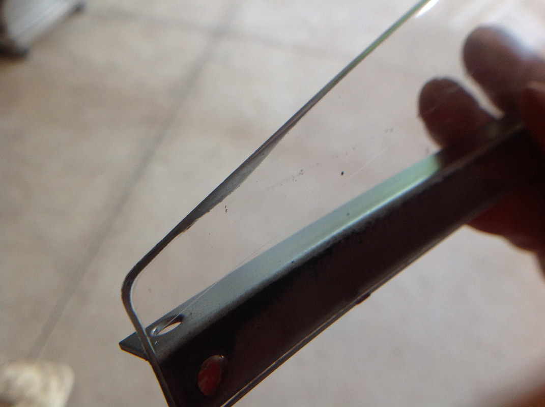

View of the guide plastic after sanding - much flatter!
- Serpent plastic was missing
- Assembly had been (poorly) welded back together
- Assembly had been painted and the paint was now worn
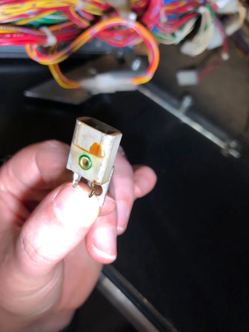
The serpent plastic is available as a reproduction (Pinball Center). It is also sold in complete plastic sets (Planetary Pinball, RTBB). The customer did not care too much about this missing plastic and did not want to make an order from Germany for a single part, so it was left out. The serpent plastic is also attached to a lamp with a green cover. This lamp is a part of the GI circuit and stays lit constantly. I have no idea what the purpose of a green lamp is here, and I think it looks a bit silly. I replaced it with a white LED with flexible leads, and pointed the LED towards the skill shot baskets. This, I think, is more useful, illuminating the skill shot instead of glowing green and illuminating nothing in particular.
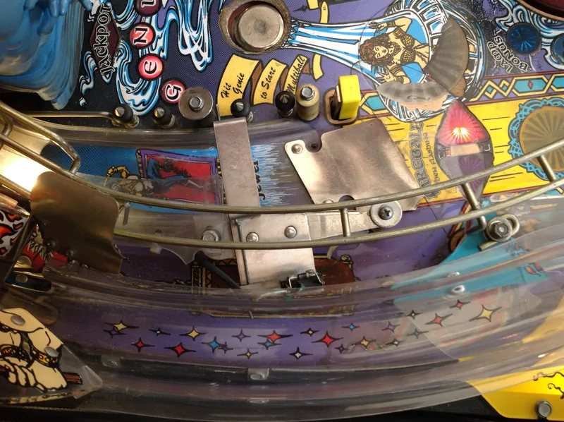
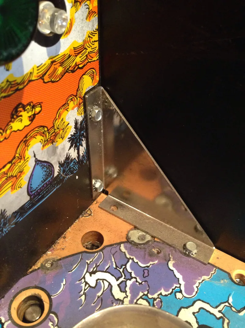
The fact that the assembly had been welded together at some point clearly showed that it had been through a lot of abuse. A lot of metal assemblies on Williams games were spot welded together, and these spot welds were usually quite weak. Most don't stand up to continued years of abuse. The scoop assembly in this game was a great example of this, and I'd previously had to reweld my subway assembly in Demolition Man.
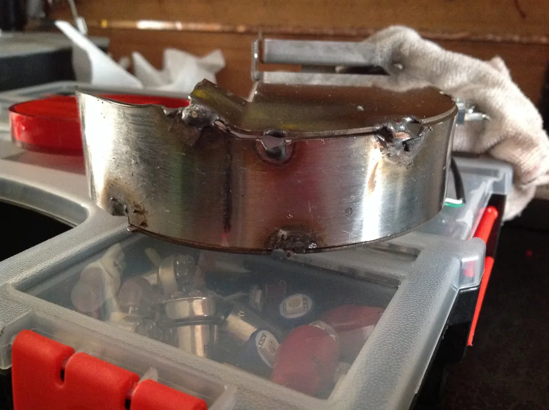
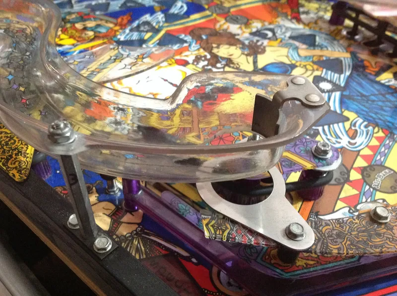
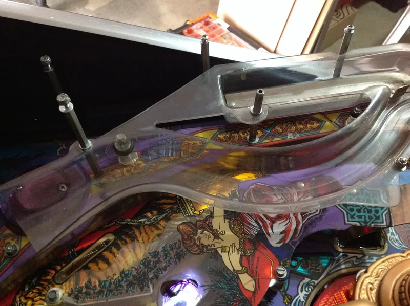
Photo of the scoop assembly, showing some welds already broken and others previously repaired.

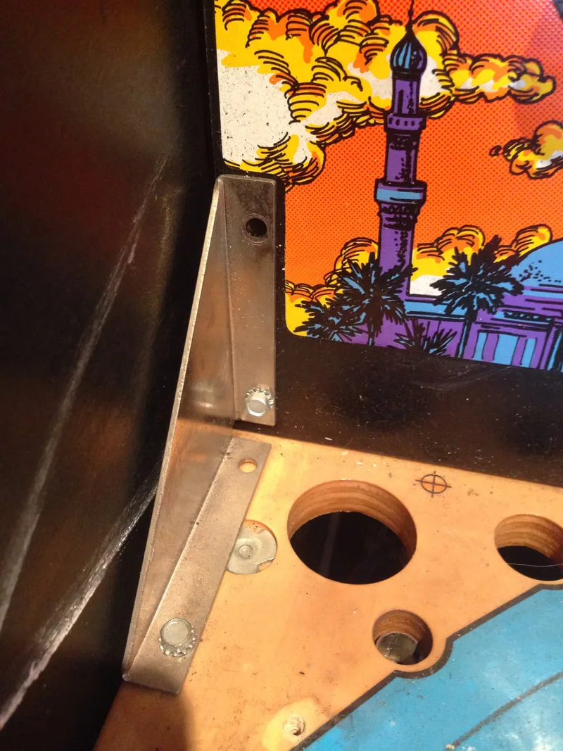
The problem with how the skill shot assembly had been welded was that the welds were huge and in close proximity to the screw holes. There are three screws that secure the assembly to the playfield, and one of them (on the left side) couldn't be screwed down all the way due to the weld metal which was now in the way. Luckily it did not matter too much, as the screw could still be tightened enough to secure the assembly. For games that have missing skill shot assemblies, or ones in poor shape, you can still buy original assemblies (PSPA), or you can even buy brand new ones (Mr Pinball, Planetary Pinball).
Next was the issue of the paint. The skill shot assembly was originally unpainted, bare metal. The one on this game had probably been painted to cover up marks from the welding. Due to impacts by the ball, most of the paint in the area surrounding the "baskets" had worn away. One option was to repaint the whole assembly. However, this area is also meant to be covered by decals on the first and second baskets. These decals were completely missing, but luckily they are readily available (PSPA, Mr Pinball).
Skill shot assembly decals installed.

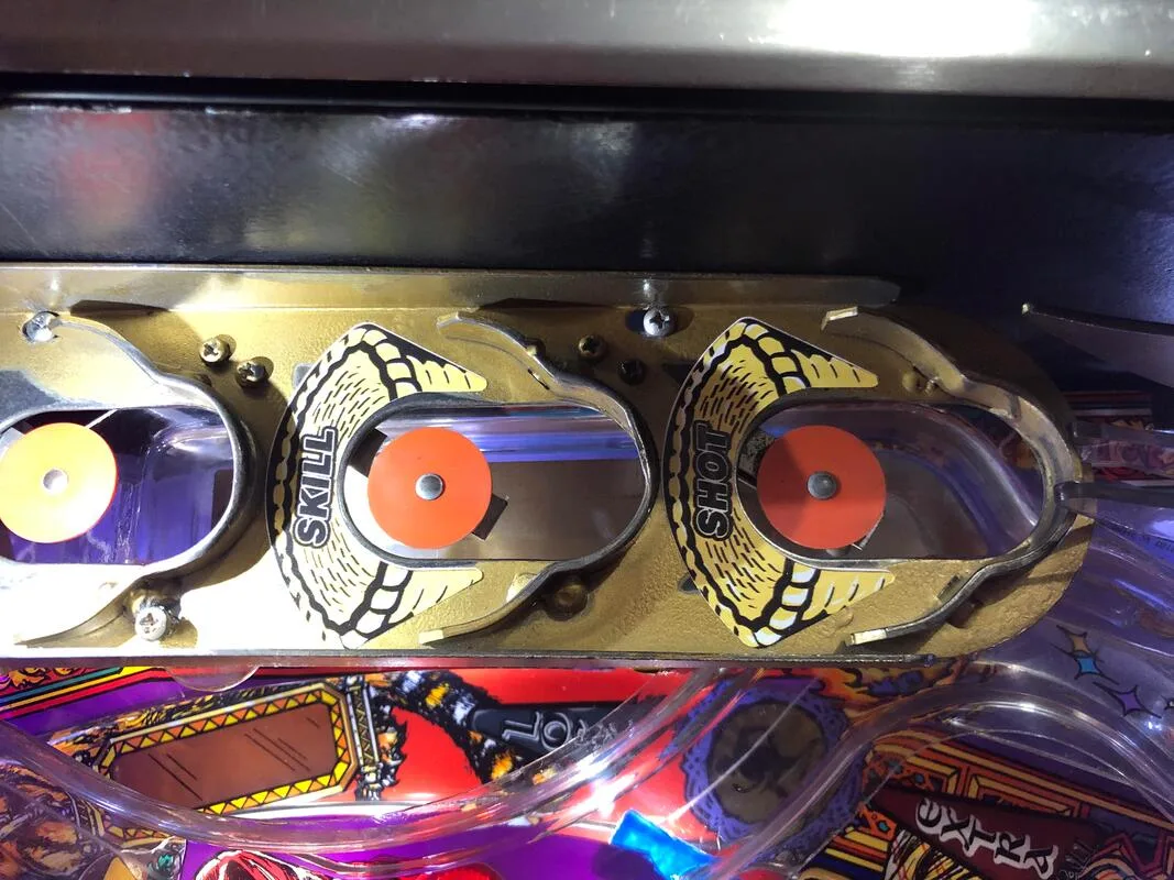
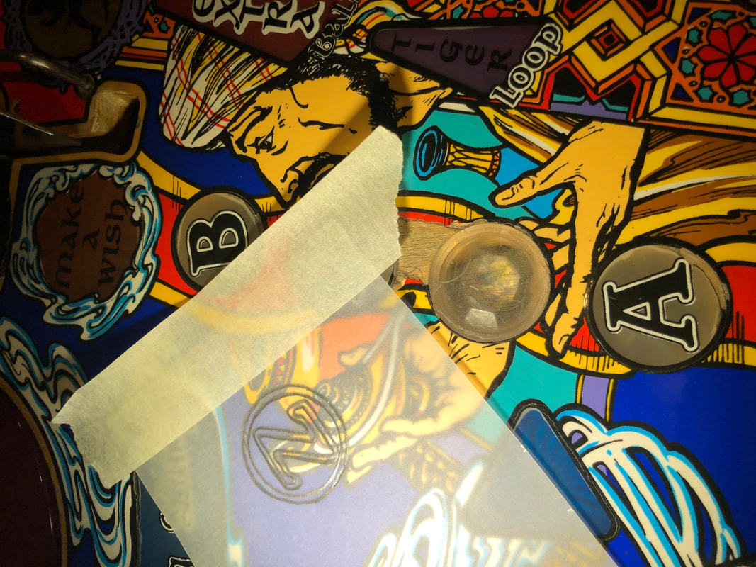
Seeing balls strike the bare metal of the assembly is pretty rough, considering how hard the ball is sometimes launched into it. While browsing the Tales of the Arabian Nights threads on Pinside, I saw this post by Pinsider zippydapinhead, who suggested using clear vinyl tubing to protect the skill shot brackets. Seems like a brilliant idea! If you don't have any lying around the house, Bunnings sell perfect lengths of tubing which you can simply slice down the middle and bend to the correct shape. Go for the 3mm diameter tube, as larger diameters will not sit securely and will fall off.
Vinyl tubing installed on skill shot brackets.

After installing the tubing and using a hair dryer to melt it slightly and bend it to size, I played a few test games. No matter how I bent the tubing or how I formed it with heat, it would always come off after being hit by the ball several times. Some have suggested using glue, but I don't like the idea of pouring glue all over the assembly. Glue does not withstand direct impacts very well and will eventually fracture and break, resulting in the same problem. Superglue may be a potential solution but it is not ideal as I don't like adhering mods to the playfield which can never be removed.
Debris on the playfield is never a good thing because it hangs up balls and renders the game unplayable. So, there was only one solution - remove the tubes as they weren't able to stay attached to the assembly. If anyone figures out a way to secure these tubes to the assembly in such a manner that they never dislodge, let me know!
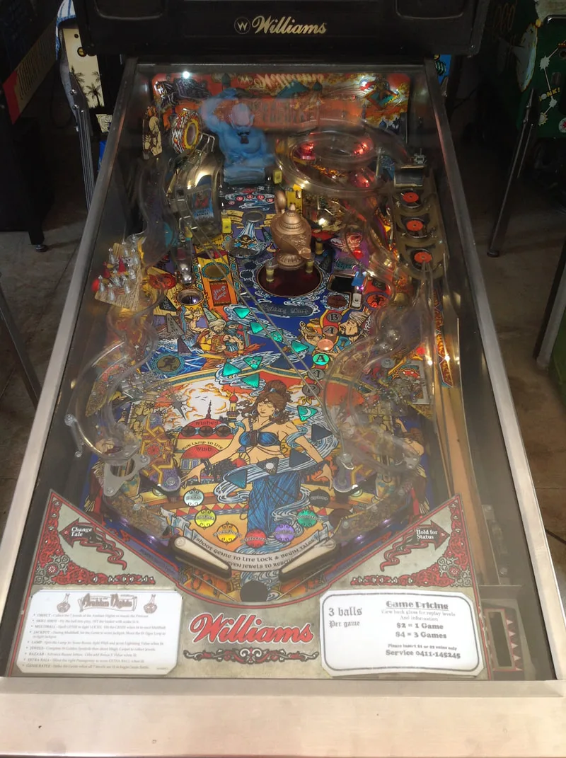
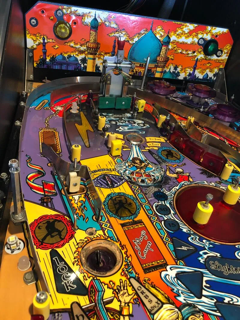
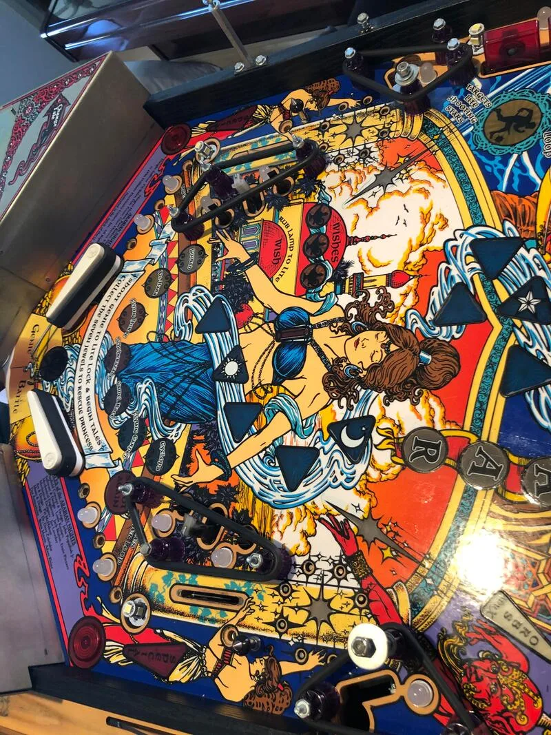
This machine was not like that. It was a players' condition machine, and had been treated as such since it was born. Being a sited machine that was on location and earning money, looking pretty was not its goal. On the other hand - playing well and earning money - was. Unfortunately, as a result of form being seen as less important than function, sited machines tend to get worn out, cosmetically damaged, and generally beat. The playfield on this game was in poor shape. There was missing artwork, wear spots, and some hideous attempts to cover up playfield damage.
For those that can't be bothered dealing with damage such as this, you can just buy a completely new playfield (CPR) and be done with it! But that was beyond the scope of work for this restoration. Instead, Fiona and I decided to see what we could do with just our paintbrushes and our wits, so we decided to repaint the damaged areas on this playfield. For all of the paint colours mentioned in the paragraphs below, we used Wicked Opaque Base Color paints (Airbrush Megastore).
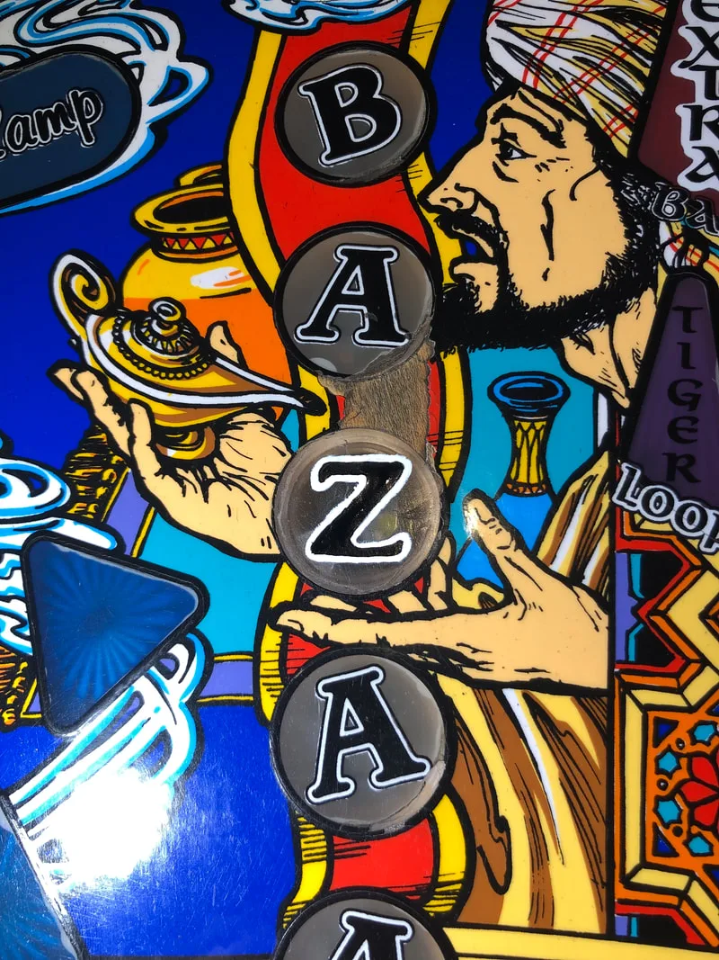
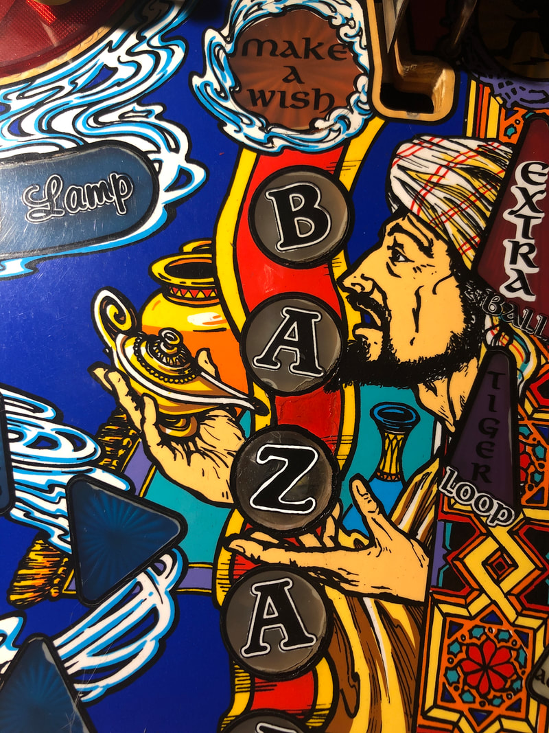
We decided to tackle the Bazaar inserts area first, as these seemed to be quite simple in terms of shapes and colours. The first step was finding an appropriate comparison or exemplar which we could base our new artwork on. Classic Playfield Reproductions are a fantastic resource in this regard, because the high resolution photos they post of their new playfields are excellent reference material. The problem was that CPR's photos were taken at an oblique angle, therefore the shape of the inserts was not perfectly square. So, we decided to look for another option. Our goal was to eventually get an accurate (to scale) print of the "Z" insert.
There are decals available for various parts of the Tales of the Arabian Nights playfield. You can get a decal overlay which covers a large area above the flippers (Mr Pinball). Or, you can get a insert decal kit which just contains decals for the commonly worn inserts (Mr Pinball, Ministry of Pinball, Pinball Center). Now, the tacky way to fix the inserts would simply be to buy the decal and stick it on. However, decals never seem to look as good as the original paint, and some decals are of poor quality. Others are an incorrect size, and don't like up properly with the original artwork. We wanted to avoid all of those issues, which is why we settled on redoing the artwork ourselves. However, that doesn't mean we can't use decals to design our own paintwork...
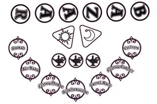
The Bazaar insert decals which were the basis for our own transfers.
The above decals were the best image I could find featuring the Z insert decal. It was not depicted as its actual size, so I used Photoshop to blow up the Z decal to the size it actually was on the playfield (measured with a ruler). Then, I used some sharpening tools to sharpen the lines of the Z, which were blurred as the original image was low resolution. Once that was done, a little touch-up was required in Photoshop to ensure the lines were nice and straight and there were no artefacts on the image. Then, it was printed out onto normal paper. This image was then traced onto tracing paper with a pencil to create a transfer sheet. The tracing paper was then turned over, and the trace of the Z was replicated on the reverse side of the page. The idea was to have lead on both sides of the transfer sheet.

Tracing the Z insert decal to create a transfer.
With the transfer paper ready, we could now transfer the outline of the Z onto the playfield insert. The sheet was placed with the Z facing upward, over the centre of the insert (easy to do as it was a 1:1 image) and taped into place with masking tape. The Z was then retraced with a pencil. The act of doing this transferred the lead from the underside of the transfer sheet very faintly onto the insert surface. Finally, we had a faint "Z" drawn onto the insert, which we could then use as a guide for painting.
In terms of colour, this insert was easy. The black inner Z character was painted first with Jet Black and a very fine brush. Then, the white outline of the Z was done in Opaque White. It was a bit tricky to get a nice, straight line with an evenly wide white border. Finally, the thin black outline of the Z was done. This helped cover up any out-of-bounds painting of the white backing. The insert keylines around the outside were then simply touched up as necessary. By the end of it, we had a neat letter Z which was quite a faithful reproduction of the original.
Painting of the white background and the Z character.
Z outline and keylines now complete.

This area was almost complete. Just the red and yellow strips between the A and Z inserts required filling in. Once they were done, the man's beard could be touched up as the very tip of it was adjacent to the A insert, and had been worn away. Doing the wiry hairs of the beard needed a lot of fine brush work! Then, at last we were done! A strip of Mylar (Mr Pinball) was installed over all of the Bazaar inserts as the scoop can eject balls on top of any of them.

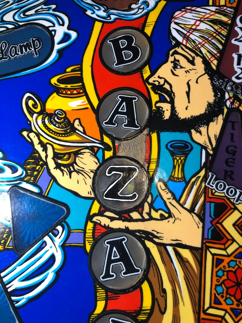
Completed repairs to the Bazaar inserts.
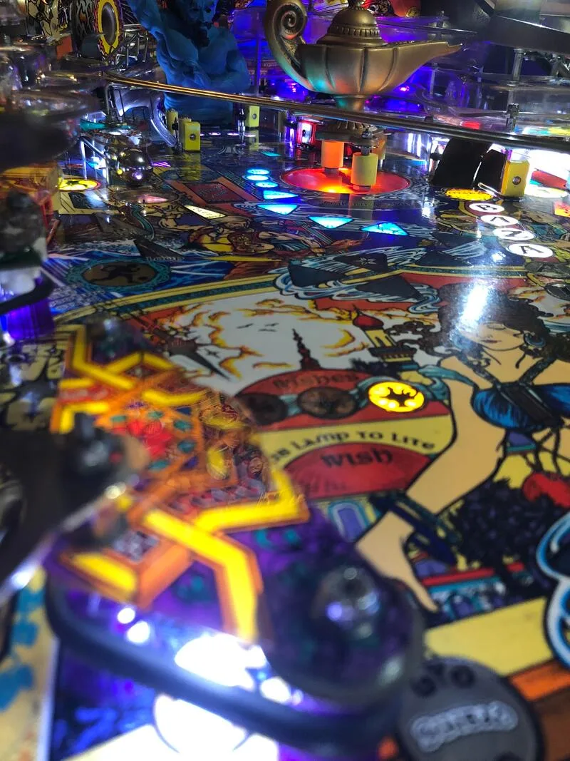
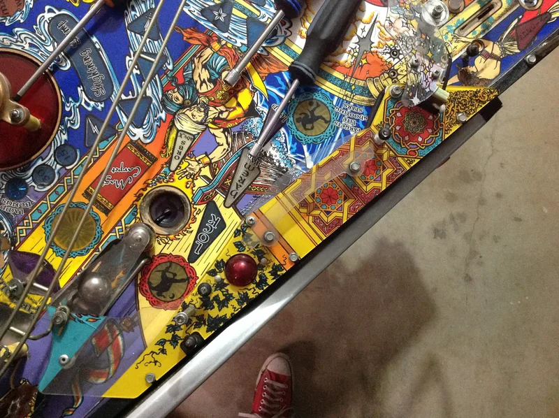
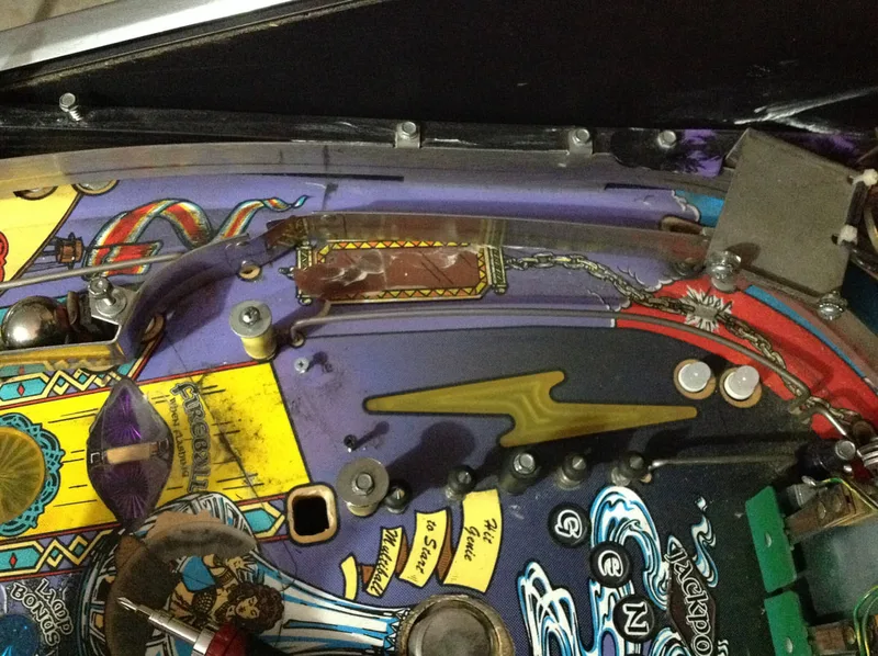
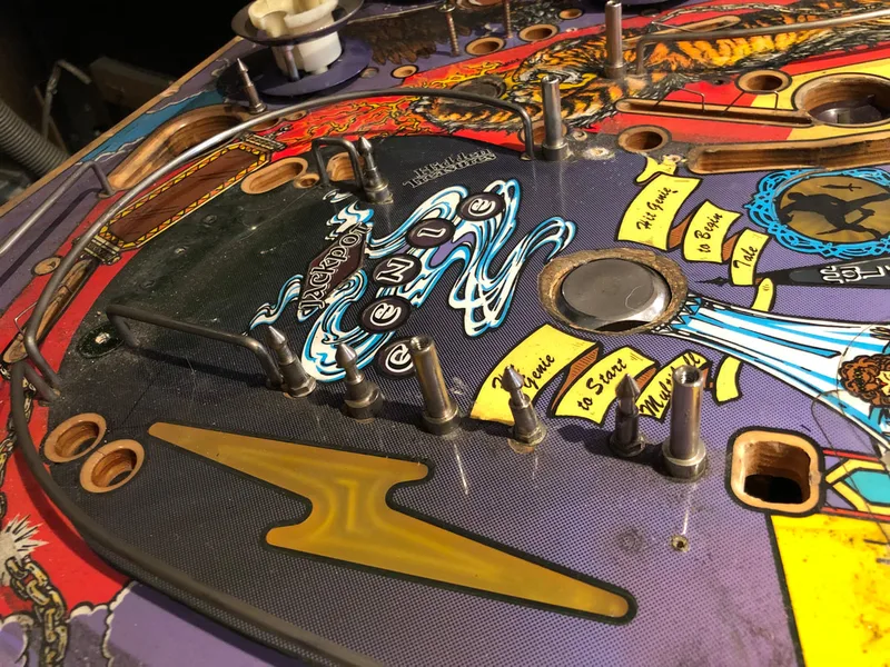
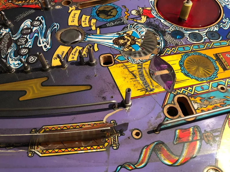
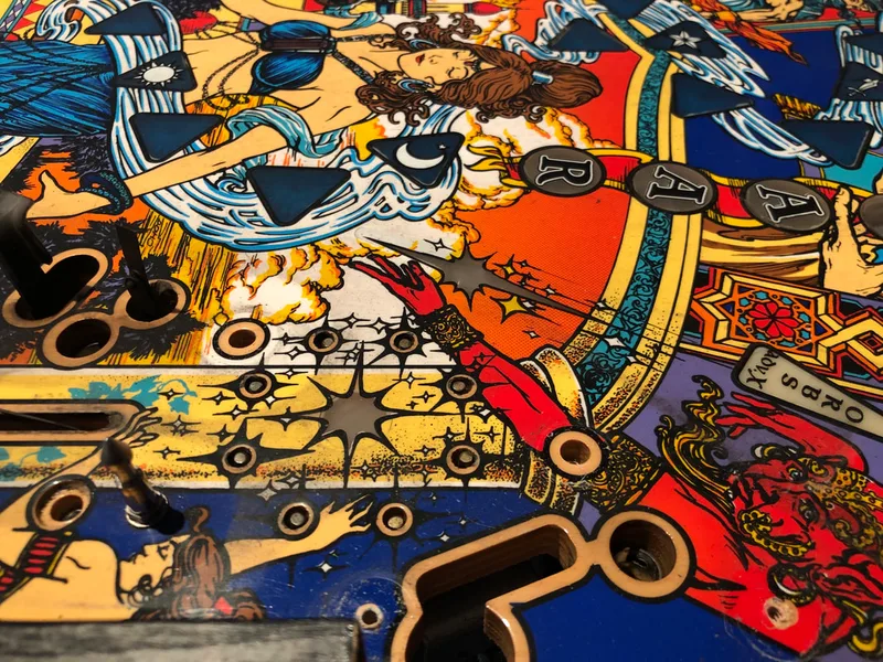
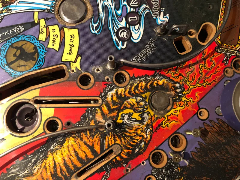
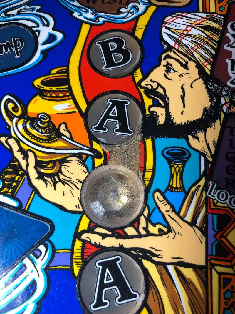
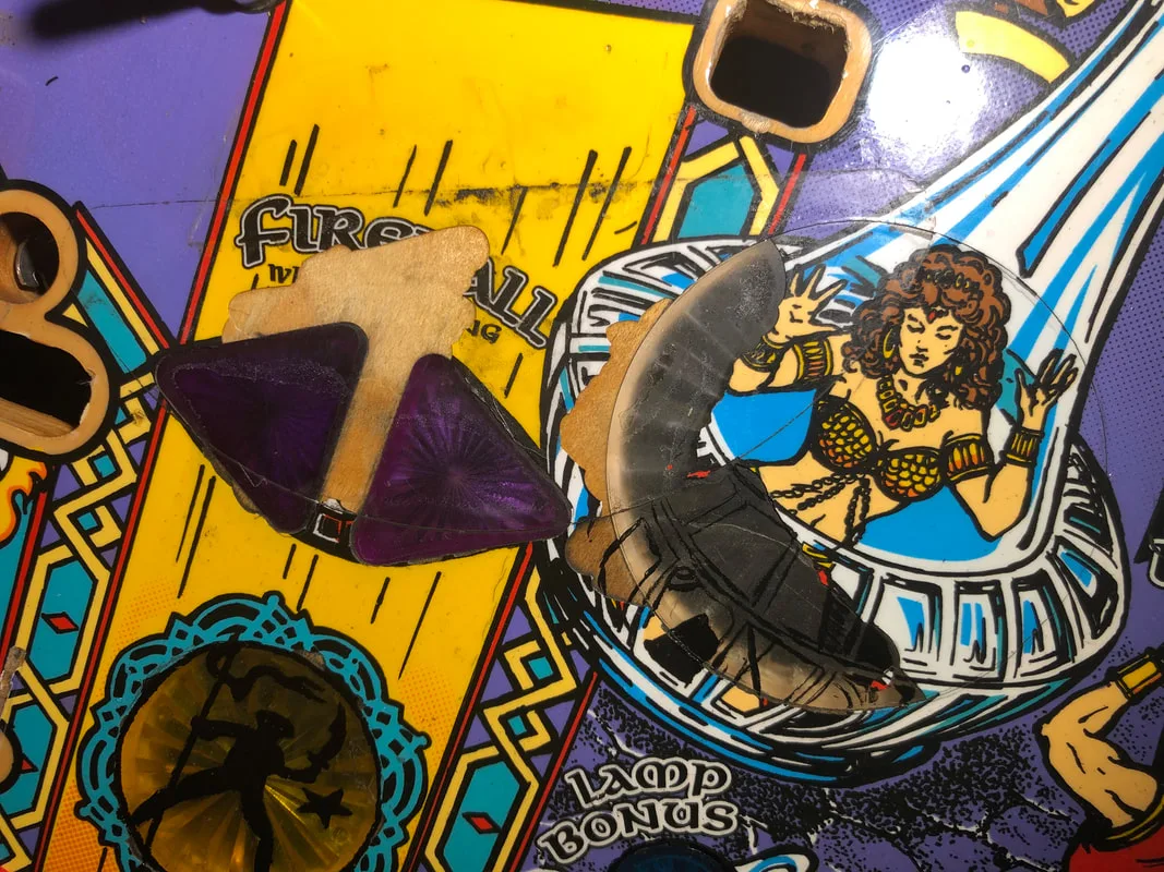
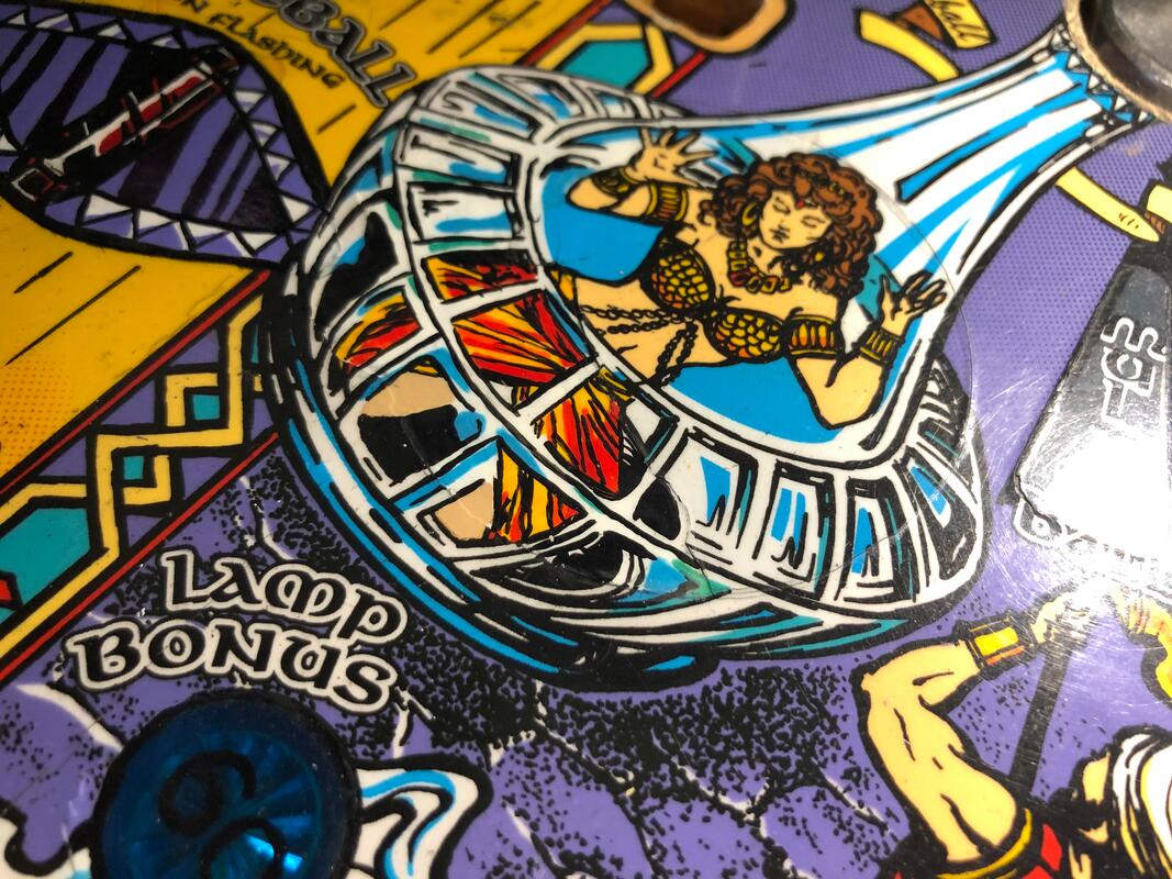
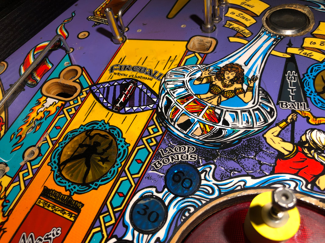
Next, we moved onto the most damaged area of the playfield - the area around the ramp entrance. Multiple inserts in this area had been damaged, including the circular golden symbol, the fireball arrow inserts, the lamp insert, and the 60 lamp bonus insert.

Severely damaged inserts around the ramp entrance.

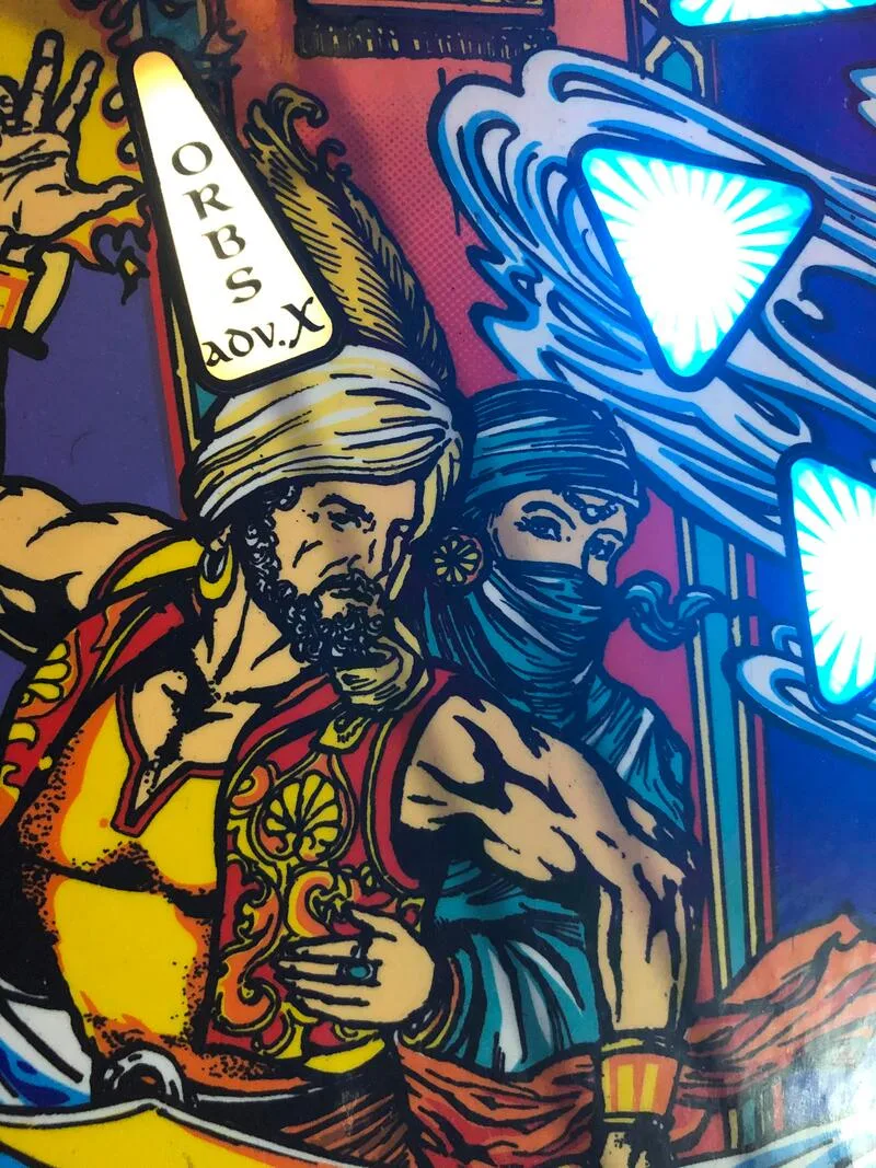
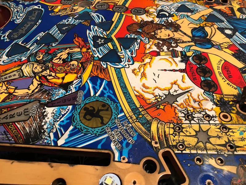
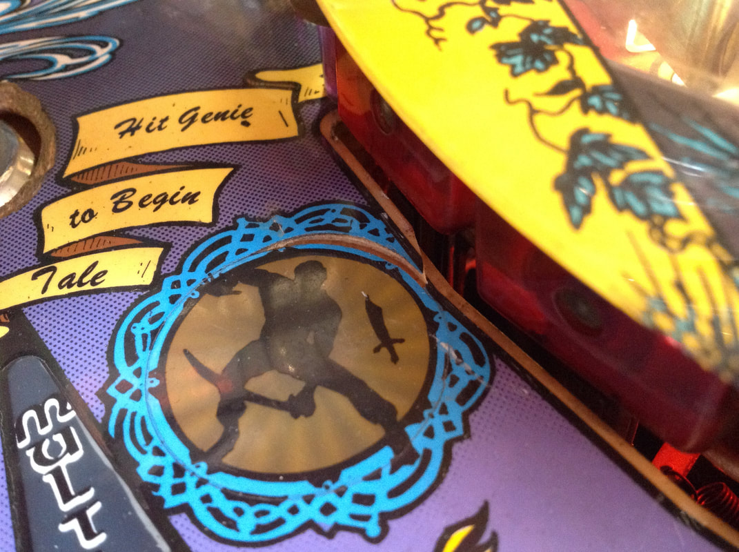
We started with the easiest insert first - the golden symbol with the green border (labelled as "Action 3" in the manual). This was a circular insert with the silhouette of a person in black. While we could have used a tracing technique similar to the one we utilised for the Bazaar inserts, this figure was simple enough that it could be replicated by hand without too much trouble. Again, we relied on some reference images and videos found online to base the figure on. The figure was painted using Jet Black.
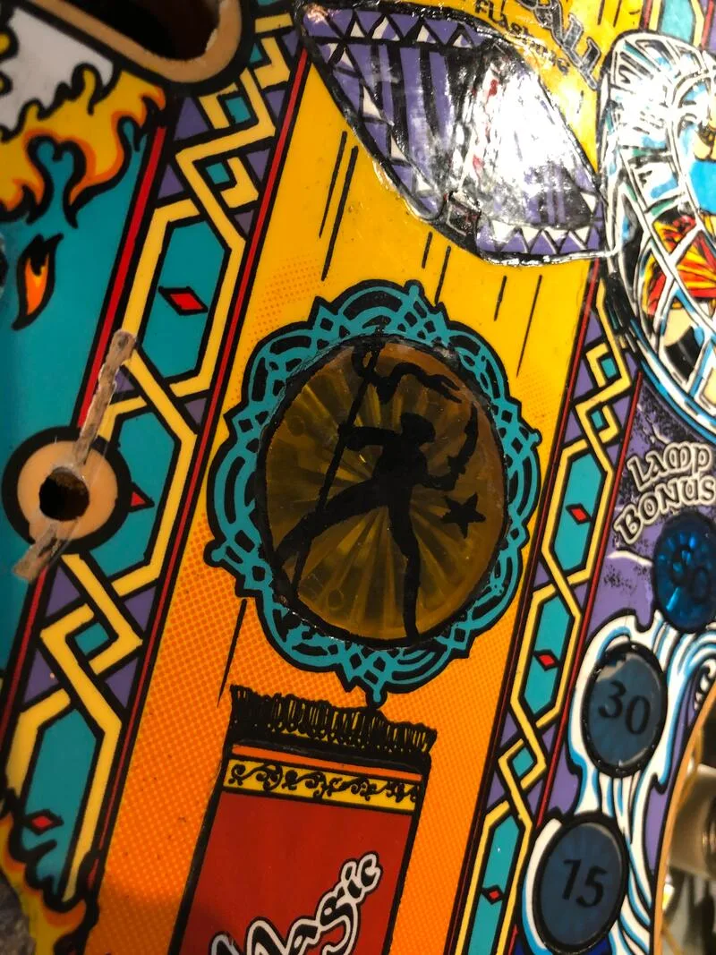
The golden symbol insert with figure silhouette freshly painted on.

Next, we moved onto the lamp (start tale) insert. There was a lot of work to do here, starting with removal of a Mylar patch which had been installed previously. This section of Mylar was already peeling slightly. It came up with some encouragement, using freeze spray to destroy the adhesive and a plastic razor blade to slice through it.

Mylar removal in progress.
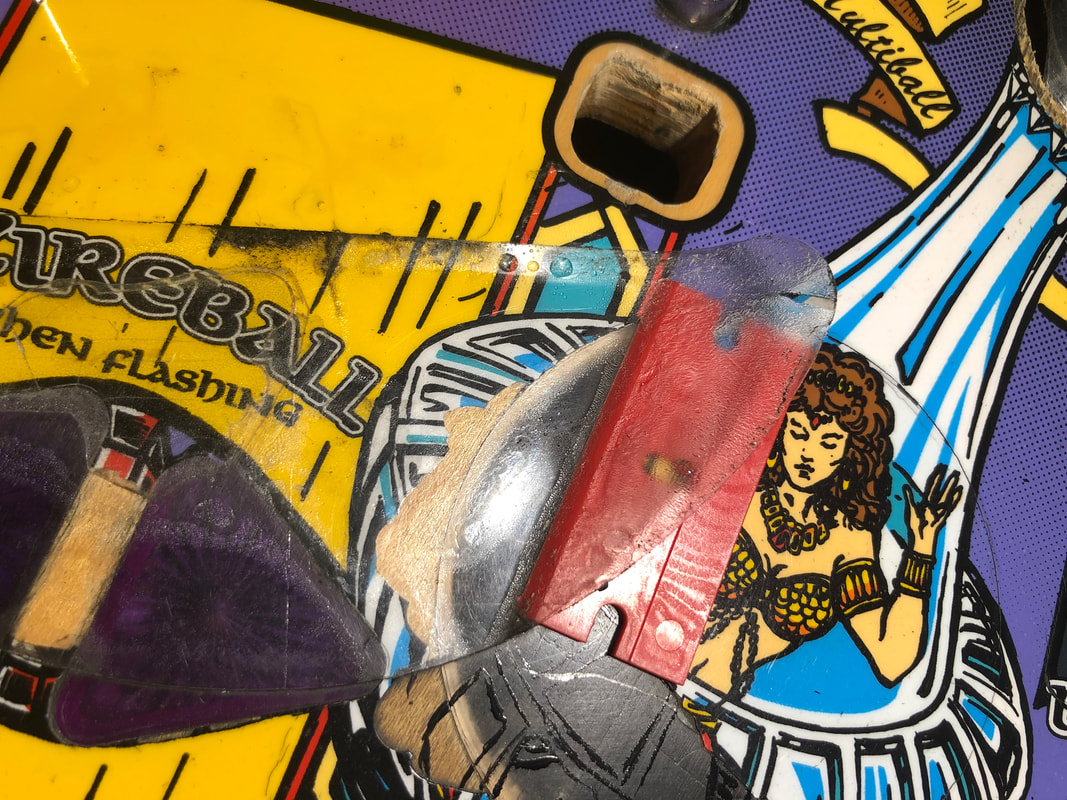
Unfortunately, the Mylar removal did result in additional damage. Some small flecks of paint on the lamp were removed. We also discovered that a patch of paint including most of the "FIREBALL when flashing" text had actually peeled off the playfield previously, and had been stuck down and sealed with the Mylar we just removed. So, of course, when the Mylar was removed, so were the paint chips with the text on them. Luckily, these sections of paint were quite large, and could be removed from the underside of the Mylar using a scalpel without breaking them up. We saved these for later, when we were repairing the purple arrow inserts.
Loss off additional paint when Mylar was removed.

At this point, we were ready to begin the painting phase. You can see how we started this part in the photo above, where some trial keylines were drawn on the lamp insert. These were later covered up, but it gave us an idea on where specific colours would be deployed. Like the figure on the golden symbol, we didn't use a tracing method to draw the detail on the lamp. However, we did have a very handy item of reference material. In the game's coin box, we found a promotional decal which was a copy of the lamp on the playfield. Now, this decal probably could have been stuck on the playfield, but it was not printed on transparent stock and had white backing paper. This would not look good if stuck directly on the playfield. Playfield decals must be transparent, otherwise they stick out like sore thumbs. But this decal was precisely the correct size and had accurate playfield colours printed on it, so we used it as a guide to duplicate as exactly as possible. This decal is readily available, too (PSPA, Mr Pinball).
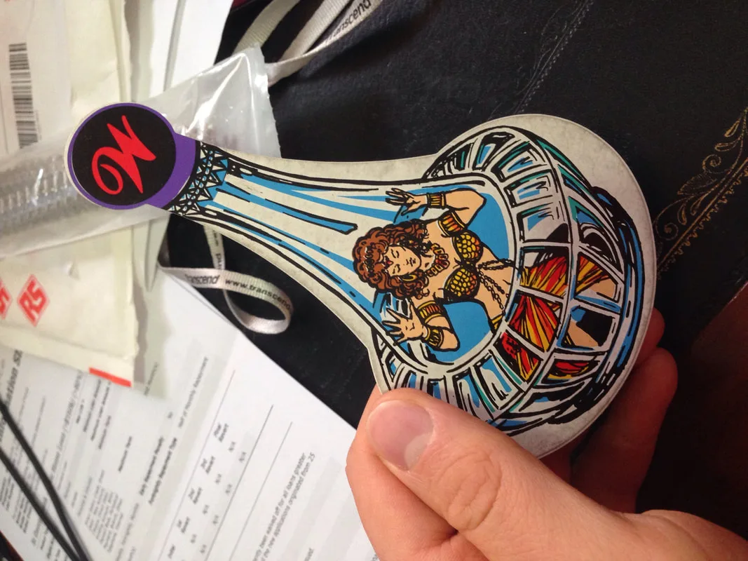
Lamp decal with white backing which was used as an artwork reference.

The lamp insert is a smorgasbord of colours. There's blue, aqua and white for the lamp, red, orange and yellow for the princess's skirt, a pale skin tone colour, and black for keylines and shadows. We painted over the entire missing lamp area with Opaque White as a basecoat. A few layers were required to build up a good, even covering. Next, the black keylines were drawn using Jet Black, which separated the various window sections in the lamp. Fiona used a 10/0 brush for this which allowed for some nice, fine lines to be drawn.
Next, the aqua and blue areas were filled in, which represented the reflections in the lamp glass. I had to look twice, as initially I had no idea there was an aqua colour used on the insert at all. They all looked blue to me! The light blue colour was a perfect match with Laguna Blue. The aqua was a mixture of Apple Green and Laguna Blue. Since these areas were all adjacent to some of the black keylines, some of the keylines had to be redrawn to cover up stray aqua and blue lines.
The princess's skirt colours were next. There are actually three colours which make up the skirt - yellow, red and orange. The yellow colour was a mixture of Golden Yellow with a dash of normal Yellow. Using this mixture, we covered the entire skirt area so the other colours could be built on top. The skirt colours were painted from lightest to darkest (yellow, then orange, then red). The orange colour was made up of an Orange base mixed with some Golden Yellow. The reddest colour of the skirt was actually mostly Orange with a bit of Red.
The skin tone was added next, and was a surprisingly difficult colour to mix. This colour took the longest to mix out of them all. Brown was the base colour with smaller amounts of Golden Yellow, Red, a touch of Red Oxide, Jet Black and Opaque White added as necessary to get exactly the right shade. I'd like to say exactly how many drops of each were added to create the mixture, but it took so long to get the right shade that we totally forgot how many we added in total! That's part of the joy of paint mixing, I guess!
Once all of those components were painted, any of the black keylines which had been covered up were again redrawn.

Lamp insert after painting is complete.
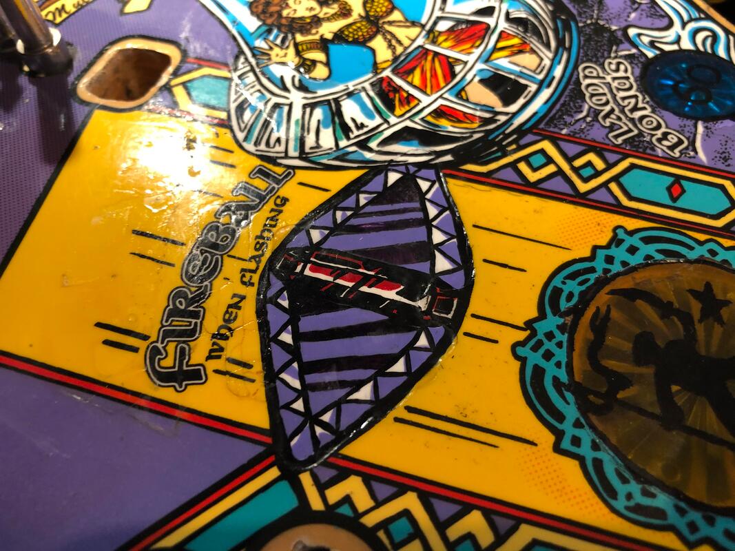
The fireball arrow inserts were an interesting challenge, because these are one of the few inserts in pinball with areas that are covered by coloured playfield artwork and other areas which are not. In the case of these inserts, a purple and white border surrounds them, with thick purple lines also crossing over them to represent the sheen of a jewel. The purple was a mixture of Violet, Laguna Blue and Opaque White. The purple lines were originally painted thicker than necessary, and the edges were not perfectly straight, so they were trimmed down using a plastic razor blade to produce straight edges.
In the centre of the two inserts is an image of a jewel. This was painted using just Red, with Opaque White and Jet Black for accents. Once that was done, we still had the issue of the "FIREBALL" text which had been removed from the playfield when we took off the Mylar. As we still had the pieces, we were able to glue them back onto the playfield and fit them together neatly. Minor touch-up was required consisting of some small yellow spots and some black lines.
Fireball text and purple arrow inserts after painting.
Almost there! There was one last area that needed attention. Below the lamp insert are the circular, blue lamp bonus inserts, labelled 15, 30 and 60. The 60 insert had been damaged insofar that the numerals had been completely wiped off. This was a much simpler insert to fix as it only needed two numbers to be painted onto it and the outer keyline to be touched up. A very small mount of purple artwork surrounding this insert was also damaged, and a bit of Violet mixed with Opaque White seemed to do the trick for that.
Now that all of the painting was done, we had to seal and protect all of the new paint. We covered each of the repaired inserts with multiple layers of matte clearcoat. There were about ten layers required to bring the surface of the insert level with the original playfield. The hairdryer came in handy to dry each layer between coats, otherwise we would have been there for days!
Finally, the entire repair area was covered with a layer of Mylar (Mr Pinball). The Mylar was cut to size and extended from the golden symbol insert below the ramp entrance, to the golden symbol insert by the red standup targets (above the spinning lamp). This sealed in both the artwork repairs as well as the lifting playfield timber near the standup targets. As this entire upper playfield area gets quite beaten up, the Mylar will prevent any future damage which is bound to occur.
These repairs were the most extensive artwork repairs we had conducted to date. They took over ten hours to complete on their own, including time for experimentation with colours and trying a few different cleaning and painting methods. None of this was charged to the client as they were not concerned about the condition of the artwork in the first place. However, we saw a good opportunity here not only to sharpen our skills but also to bring a playfield back to life in ways that many others simply would not bother with. This playfield will always be a "player's grade" playfield, as there is minor damage in various other areas of the playfield which would irritate picky collectors. However, as a player's game, this playfield will provide countless hours of play to people who will probably never realise the repairs were ever conducted. When it comes to playfield repair, you know you're doing your job properly if nobody notices your work! I would like to think nobody will ever notice ours.

Playfield artwork repairs complete!
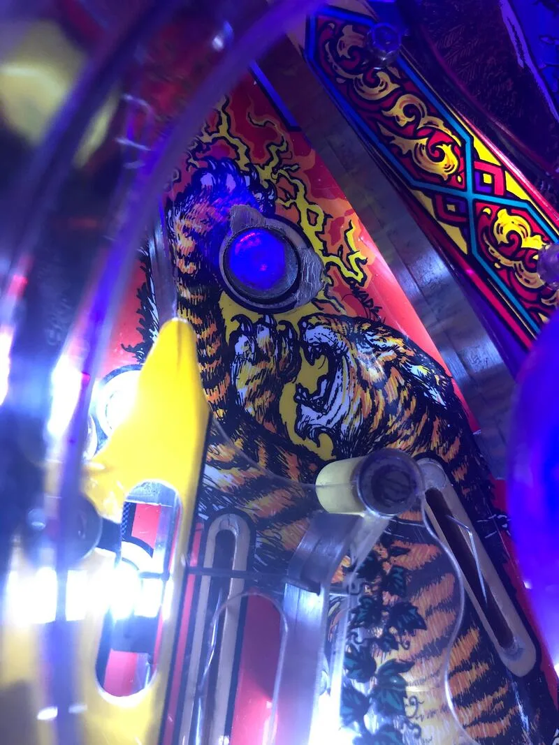
The next switch to get fixed was the left inner orbit switch. This switch is on the left side of the inner loop, which opens up (via a diverter) for tiger loops and ball locks. The most frustrating thing about this switch not working is that the game won't activate the magnet for ball locks when you shoot the left side of the orbit. The switch on the right side was working fine, so shots to the right orbit would get caught by the magnet and locked. This weird thing about this switch was that it did not work until it was fully depressed for a second or so. Then, it would work perfectly, until the game was left off for a period of time. The switch would then be dead unless you "activated" it by holding it down for a bit. Either way, it was too fiddly and unrealiable, so a new microswitch went into its place.
There were a lot of switches that had loose or completely broken off wires at the switch lugs. Wires came off one switch on the swirl ramp, one on the subway, and one of the banks of three standup targets on the left side of the playfield. I haven't had to resolder so many broken wires off switch lugs before - this game must have been shoved around a lot!
Wire broken off from the lugs of a switch on the subway ramp.

The coin mech was an electronic NRI coin rejector. Coin mechs are simply devices which sort coins of different sizes, determine they are legitimate currency, then trigger a switch based on the currency value of the coin. When playing with these mechs, a very handy resource is the Coin Door NRI Conversion for WPC document which contains instructions of how to program, install, and set up NRI coin mechs. Coin mechs communicate with the CPU board via a coin door interface board mounted to the left side of the cabinet interior, near the tilt bob.
The first issue was getting the mechanism to accept $1 and 20c coins. It was a universal mechanism and had the ability to accept these coins, so it was a matter of programming it properly to do so. I had to check the DIP switch settings on the coin mechanism itself. This is a series of eight switches inside the coin mechanism itself which tells it what type of currency to accept. To open the mech, simply push down on the button on the exterior case and then pull away from the body of the mech.
Looking at the DIP switches, I noticed that they weren't set correctly for Australian currency. It would definitely help if they were! Once they were set correctly (switches 3, 4, and 5 to ON, switches 1, 2 and 6 to OFF), the mech started accepting the $1 and 20c coins. BUT, it wouldn't touch $2 coins anymore. I double checked the DIP switch settings and they were 100% correct. Nothing I could do would make it accept $2 coins. Through experimentation, I figured out that it would accept $2 coins if I set the DIP switches to NZ currency (only switch 4 and 5 ON). I have no idea why this is the case, but it worked!
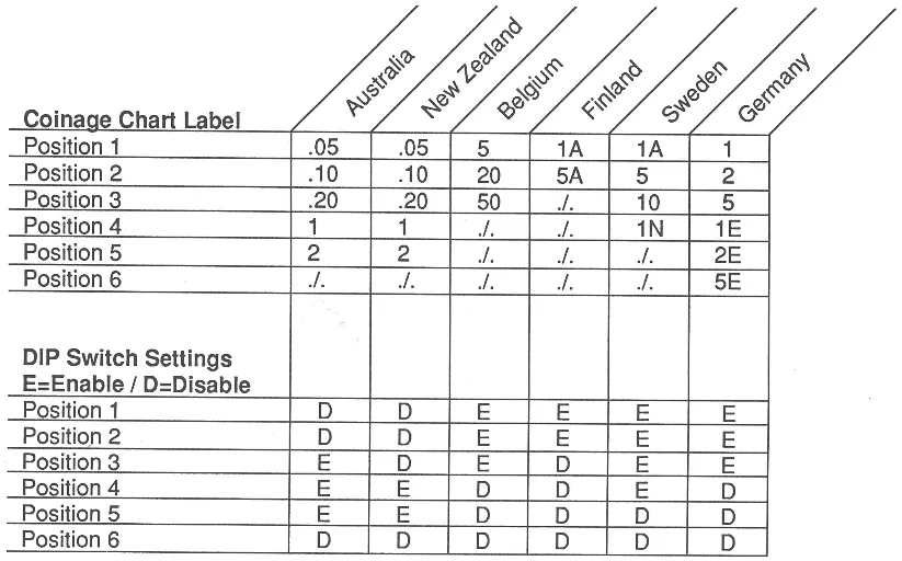
Excerpt from NRI coin door conversion document showing switch settings.

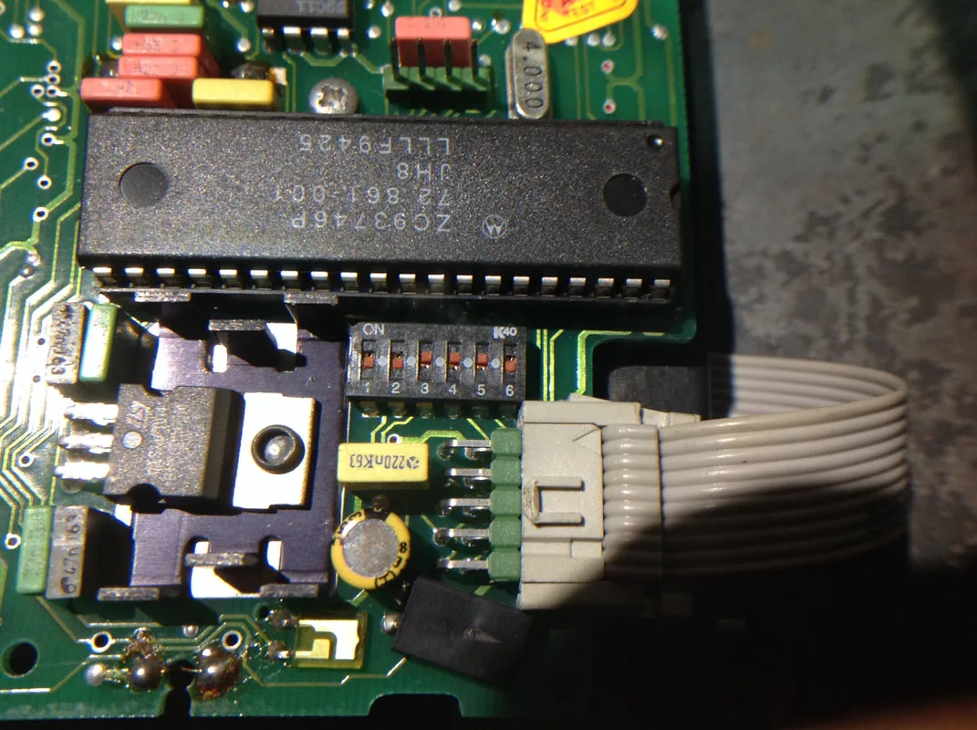
Coin mechanism circuit board, showing DIP switches set to AUS currency.

The next issue I noticed with this setup was that the ribbon cable connected to the coin mech was attached to a 0.156" Molex connector connected to J4 on the interface board. The connector had wires hanging all over the place, and one of them came out after I tugged on it. Definitely not a reliable connector. Perhaps this was another reason why coins were not registering correctly.
Original ribbon cable with wires all over the place!
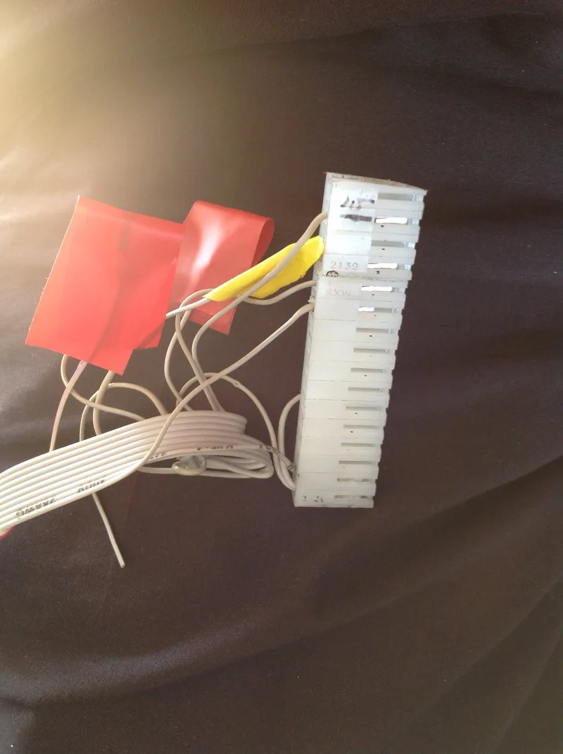
Some of the wires fell out when tugged and were not crimped properly.

So, I had to remake the ribbon cable. I copied a ribbon cable from one of my other games, which was connected to a Microcoin QL coin mechanism. All you need is a 15-position female Molex connector (RS Components, RTBB) and 0.156" crimp terminals (RS Components, RTBB). Alternatively, an IDC connector can be used, but I didn't have the correct size in stock, so I went with the Molex style. Strip the ribbon cable at one end, being careful not to cut it, as it is is very thin. When crimping, you will need to use a small size crimp due to the thinness of the wire. Make sure the wire is clamped nicely in the crimp, as if the connection is not perfect, you will get intermittent coin registrations. If you're not as much of a sucker for punishment as me, you can also buy a ready-to-use ribbon cable, complete with connector (Mr Pinball, PSPA).
|
Ribbon cable wire number |
J4 connector position (pin 2 = key) |
|
1 (red) |
NC |
|
2 |
5 (coin 4) |
|
3 |
14 (coin 2) |
|
4 |
15 (coin 1) |
|
5 |
3 |
|
6 |
NC |
|
7 |
NC |
|
8 |
NC |
|
9 |
4 (12v) |
|
10 |
1 (GND) |
You can either get all of the coins to register their correct values by swapping the pins around on the J4 connector so they match up with the default coin slot values (default values are listed in the manual). However, default values only allow you to use three denominations ($2, $1 and 20c). Or, you can adjust the different coin slot values manually in the pricing adjustments menu (set adjustment A3 10 to custom, then set the coin slot values in A3 12-15). The latter option is potentially easiest, and allows you to use more than three denominations, but keep in mind that all of those pricing adjustments will be lost if battery power is interrupted.
Rebuilt coin door interface board J4 connector.
And finally, it was all done! From a completely non-working coin mech with a butchered ribbon cable to a working mech with a brand new connector and crimped terminals. It took several hours of fiddly crimping, and a lot of trial and error with the coin outputs, but it got done.
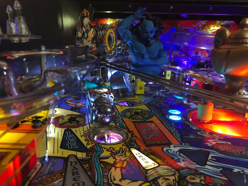
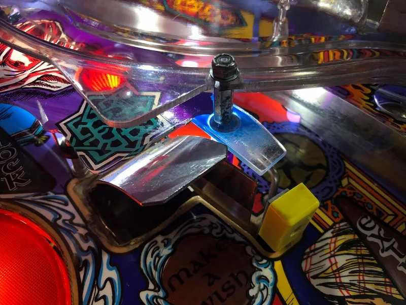
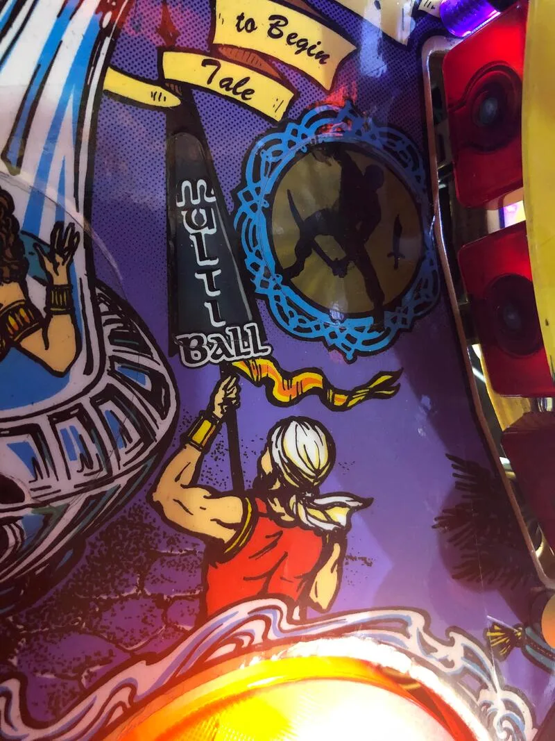
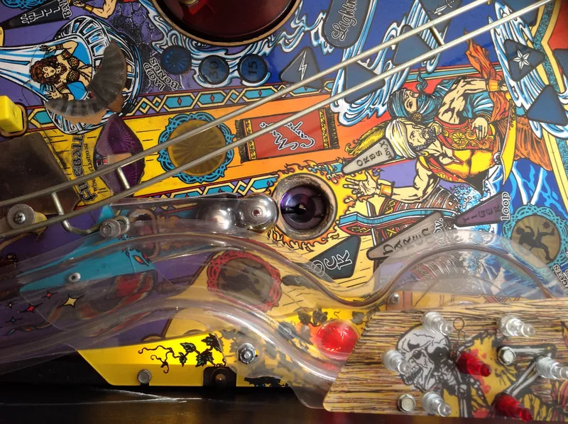
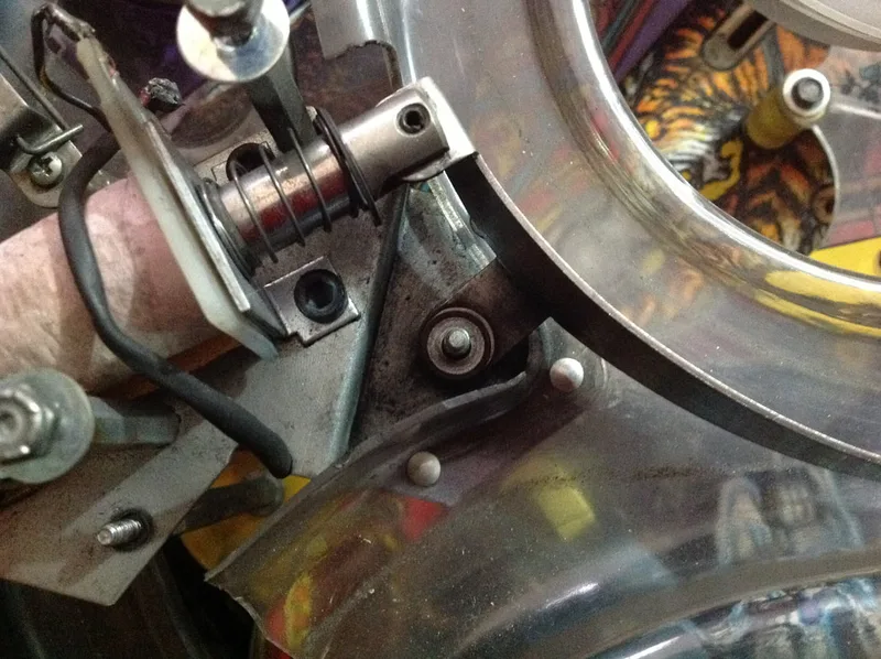
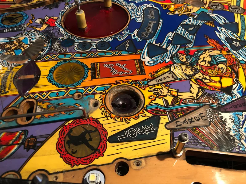
This feature did not work as inteded when we first got the game. The magnet would grab the ball, pull it underneath the playfield, but then the ball would get stuck and wouldn't enter the subway under the playfield. The magnet would then get stuck under the playfield (trapped by the ball), or would fling the ball upwards through the magnet hole again. It actually looked pretty funny, but unfortunately the game won't start multiball unless the ball enters the subway.
There were a couple of clues which indicated what the problem may be: the loud buzzing caused by the magnet coil rattling around when engaged, and the fact that the magnet core was not centred around the hole. You can see in the video above that it is closer to the bottom edge of the hole (towards the flipper) than the top (towards the genie).
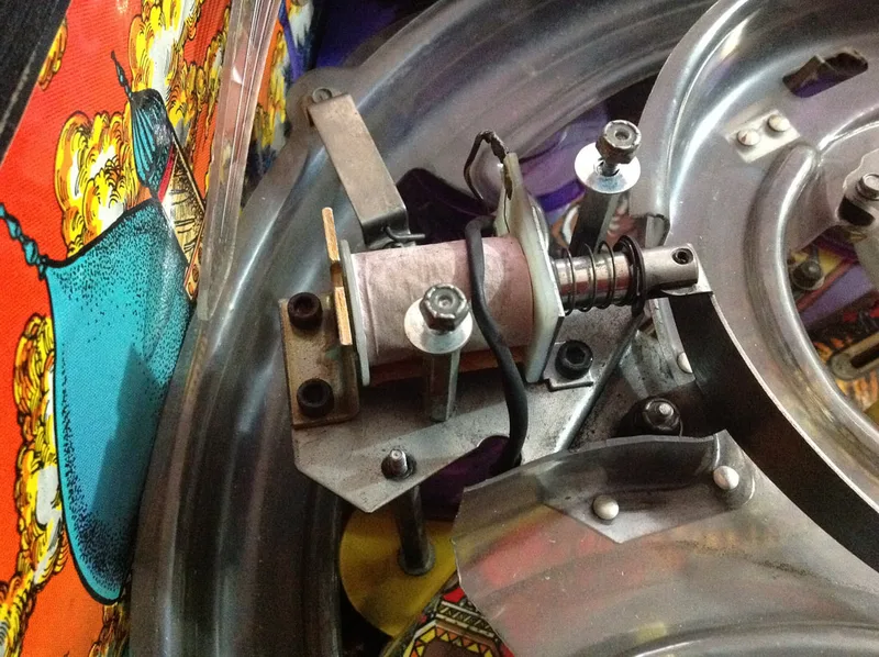
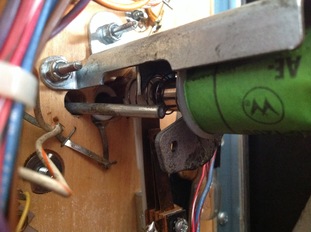
This was because the entire magnet coil assembly was loose. The magnet coil is attached to a shaft, which inserts and screws into a plunger, which is actuated by a coil. This shaft was loose, allowing the magnet to move around too much. This prevented it from making the proper clearance below the playfield, therefore preventing the ball from entering the subway. There are a few things to check when the assembly is sloppy. Are the correct springs installed? Is the shaft inserted fully into the plunger? Is there smooth movement of the shaft through the hole in the bracket?
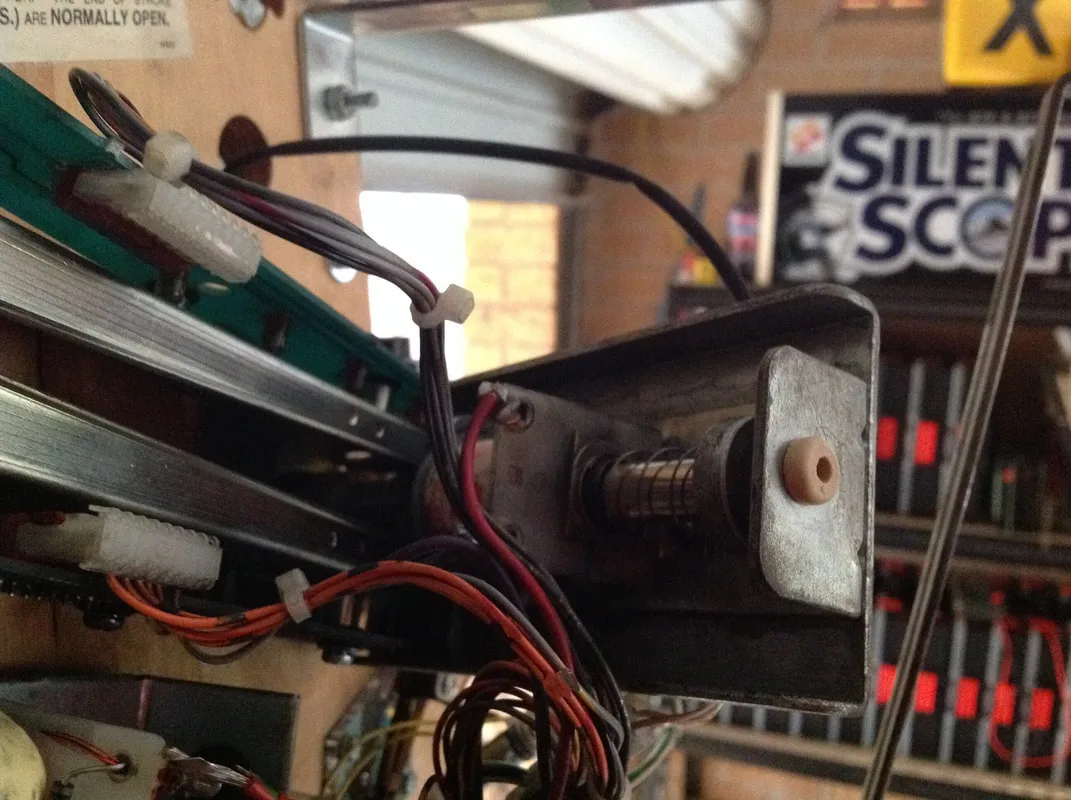
The main issue with this mechanism was the shaft was not fully inserted into the plunger, and the screw which secured it in place was a little loose. Cleaning the assembly and tightening the screws fixed this up.

Loose magnet coil shaft.
Unfortunately, the magnet still did not work consistently after that. It was better, but would still get hung up occasionally. Taking it apart again, I realised that there was some binding going on in the bracket hole where the magnet shaft passes through. There is a nylon liner here which had worked its way out of the hole and was rubbing on the shaft slightly. This was causing it to bind, and once the liner was cleaned, reinstalled, and the bracket was adjusted fit a better fit of the liner, it allowed the magnet shaft to move smoothly and freely.

Misaligned nylon liner, top view.
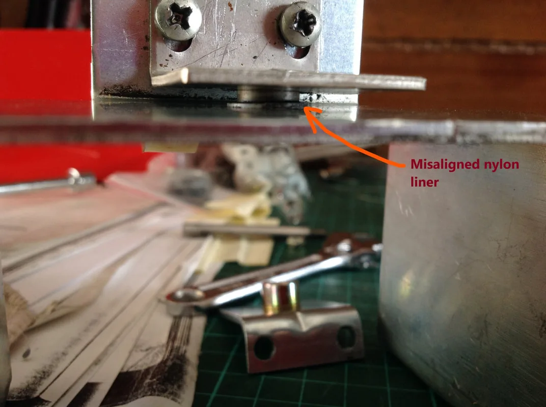
Misaligned nylon liner, side view.

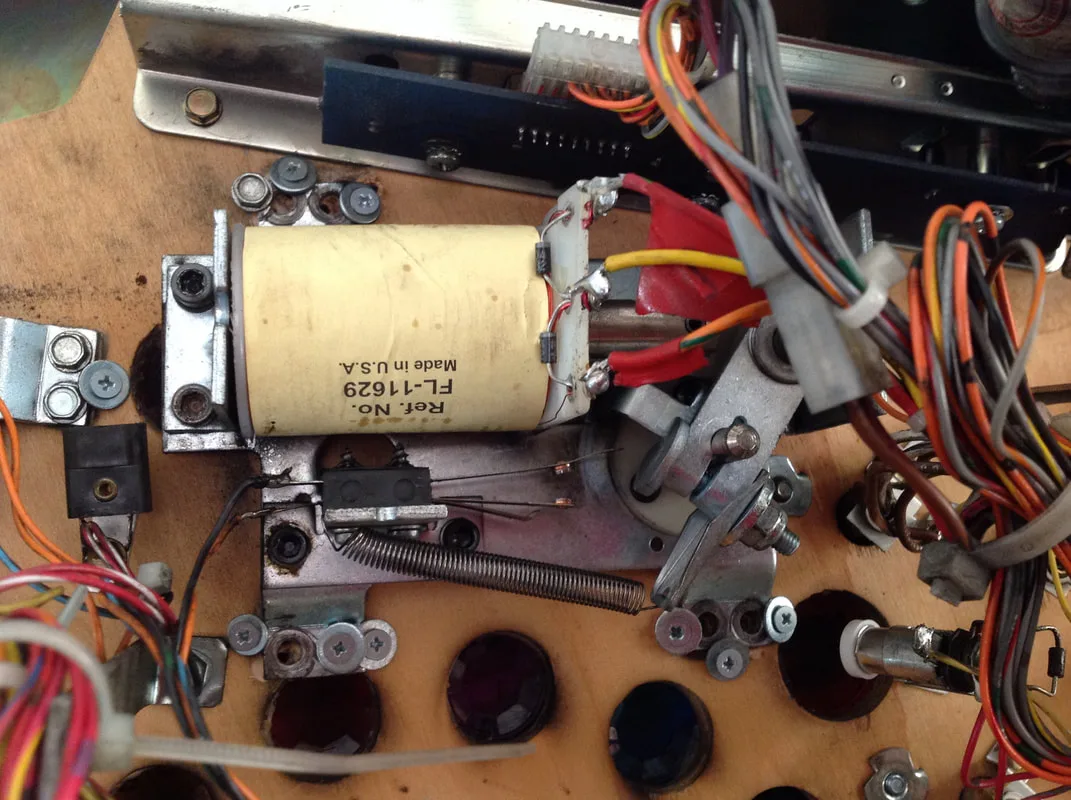
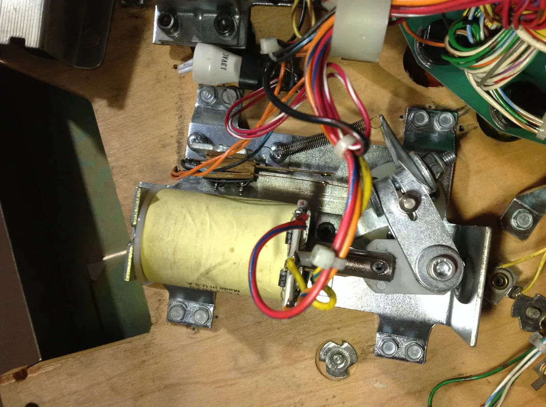
There were two other minor issues to sort out. First, the wrong coil had been installed on the bottom of the assembly. An orange (mid strength) coil (part no. FL-15411) was installed, but the game requires a yellow (low strength) coil instead (part no. FL-11753-1). You can use a regular flipper coil in its place (part no. FL-11753).
Second, the dressing of the wiring loom for the magnet coil should be checked. Service Bulletin 91 was released regarding improper positioning of the wire, which could be severed by the sharp edge of the magnet bracket. Ensure you loop the wire into a zip tie, which is then routed through both of the holes on the bracket, rather than just one. This will prevent the wires from moving.

Proper routing of the magnet coil wiring.
After all of those adjustments and fixes, the assembly worked quite well. The magnet caught the ball and delivered it to the subway consistently. A final test using the in-game test feature showed that it was working correctly.

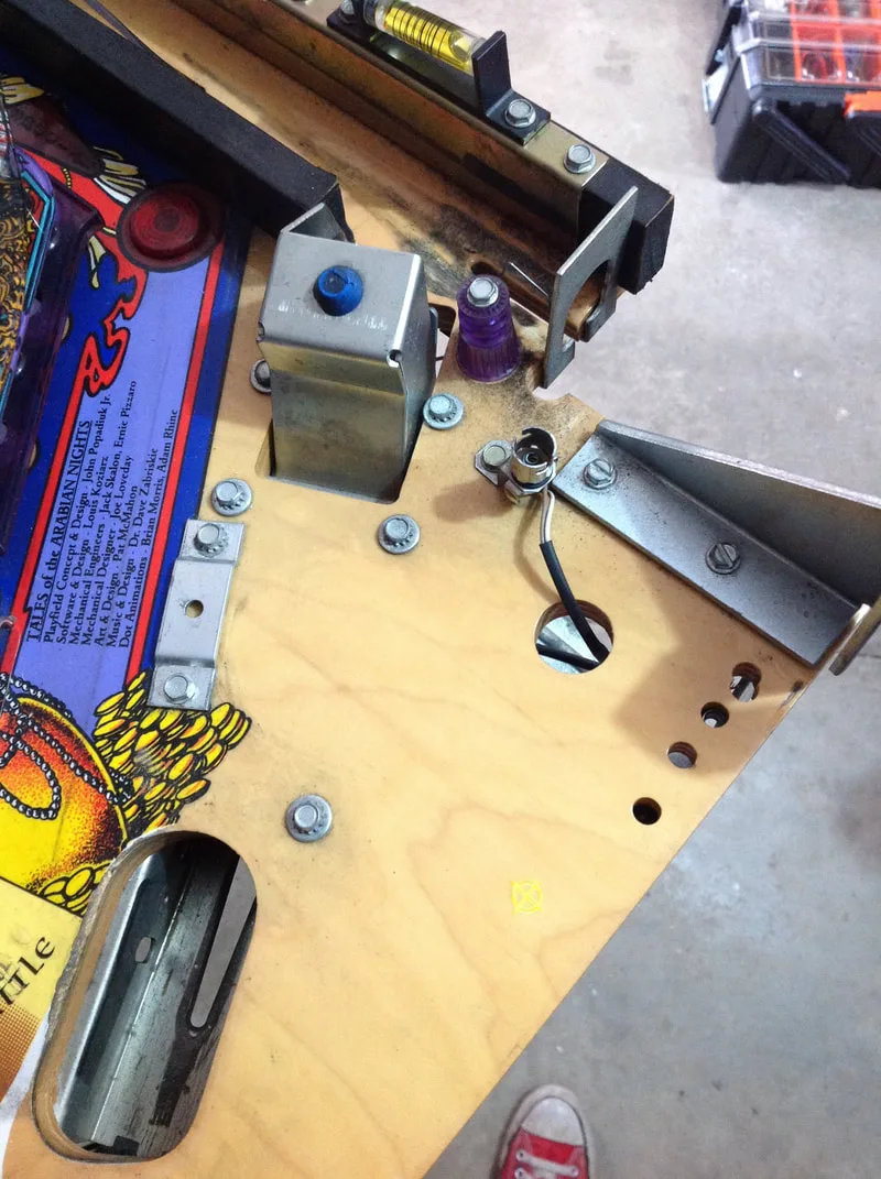
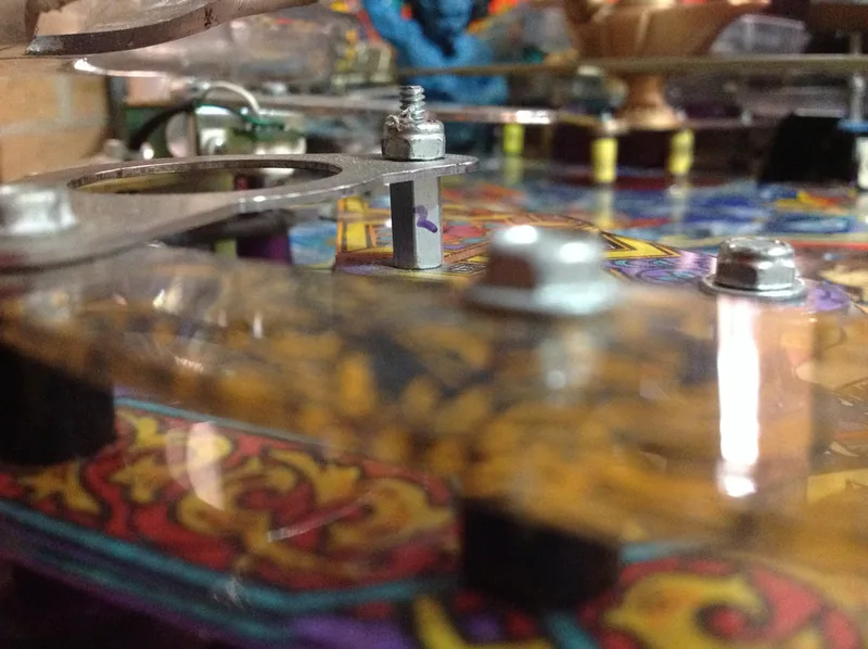
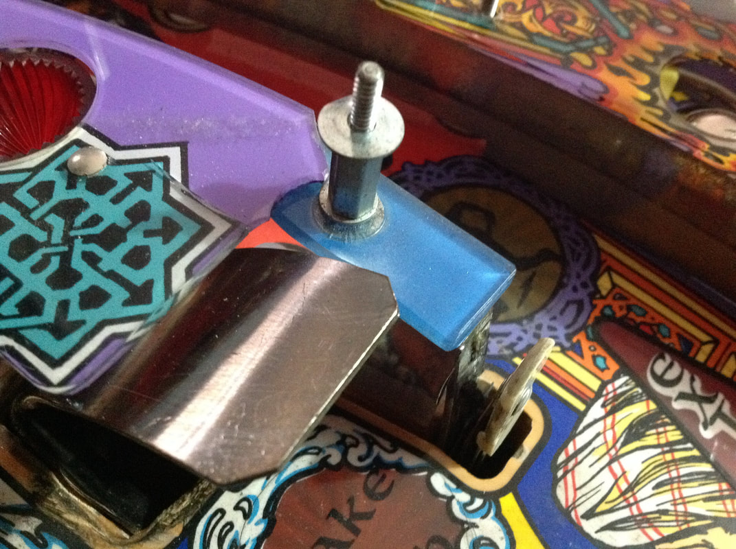
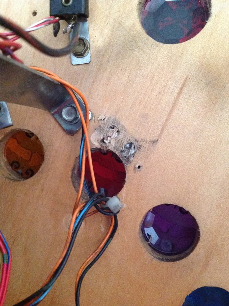
Artwork pushed upward by screw for the vanishing magnet assembly.
Artwork chipped off by flipper assembly screw.

The artwork repairs in this case were fairly simple. Since quite a large layer of timber had been pushed up near the circular insert, a bit of wood glue was pushed into the void using a syringe and the playfield wood was pushed down into place. An anvil was left on it overnight. The end result was acceptable, but it still wasn't 100% flush with the rest of the playfield. There may have been some other debris in the crack that prevented it from laying flat. This area was covered by Mylar which helped even the surface and will keep the layer of wood locked down.
The chipped artwork by the trough was able to simply be reglued to the playfield. The chips of playfield were either found in the cabinet or still attached to the playfield by a thread. We removed all of the large fragments, and simply reattached them. There were some key lines indicating where the paint had chipped, but unfortunately these were unavoidable. The key lines could be painted to give them a more inconspicuous appearance, but we left them be as they were not a priority for this restoration.
Timber reglued to playfield and secured with Mylar.

Playfield chips reglued to playfield surface.

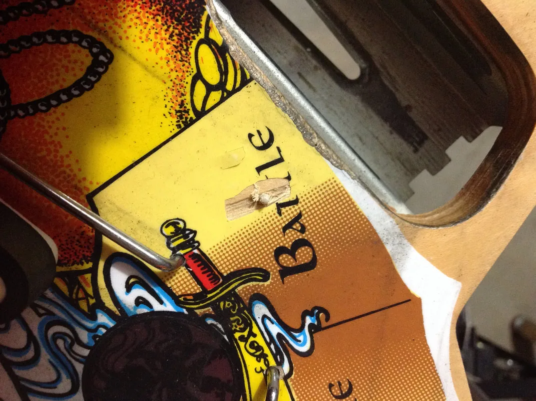
The next stage was to actually repair the gaping chasms which were created by the larger screws. Vid has a repair guide just for this type of thing, which is the procedure that I followed. Toothpicks are great for the repair of small holes, but these hogged out holes were much bigger than toothpicks. Instead, I used wooden sticks from meat skewers. They are the perfect size and the tapered end matches the shape of a screw nicely so it will sit snugly in the hole. Next time you buy a pack of meat skewers from Coles or Woolies, save the skewers! I just throw them in the dishwasher, dry them out, then put them straight into my toolbox just for these types of repairs. Dip the tip of the skewer in some wood glue, tap them into the hole, and cut them flush with the surface using cutters. If there is some space in the hole, you can stuff it with a couple of toothpicks to ensure a snug fit. Then you simply ram the new screw into the now plugged hole. The glue and screw adhere to the expanded wood which the screw has displaced, making it as secure as the original screw would have been.
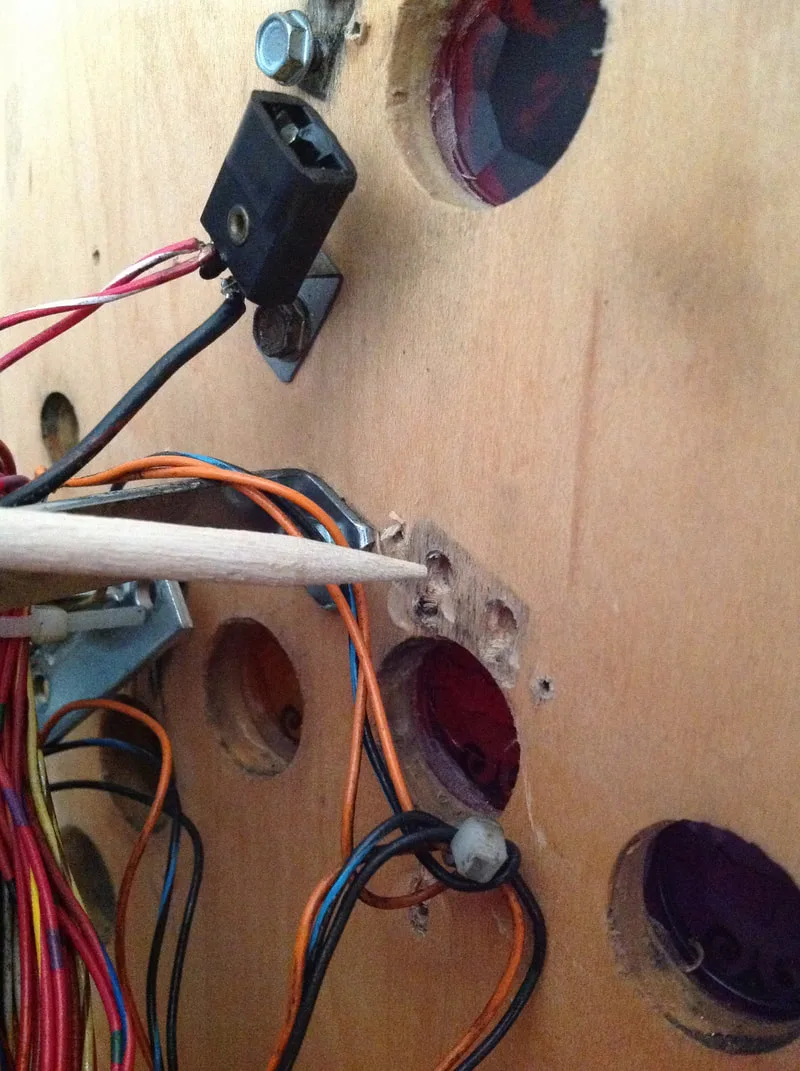
Skewer to be placed into the enlarged hole.
This is what happens when flipper assembly screws no longer fit - what a mess!

Hole now plugged with skewers that have been cut flush with the playfield.

Screw holes repaired and original screws installed.

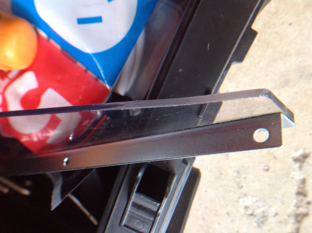
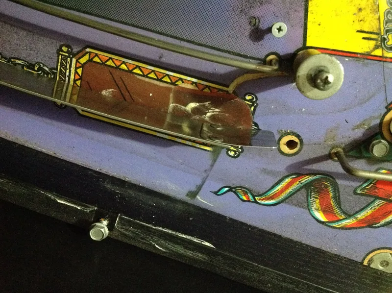
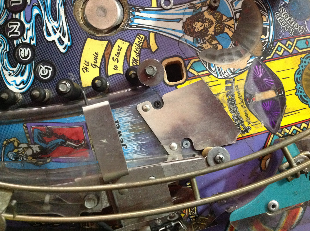
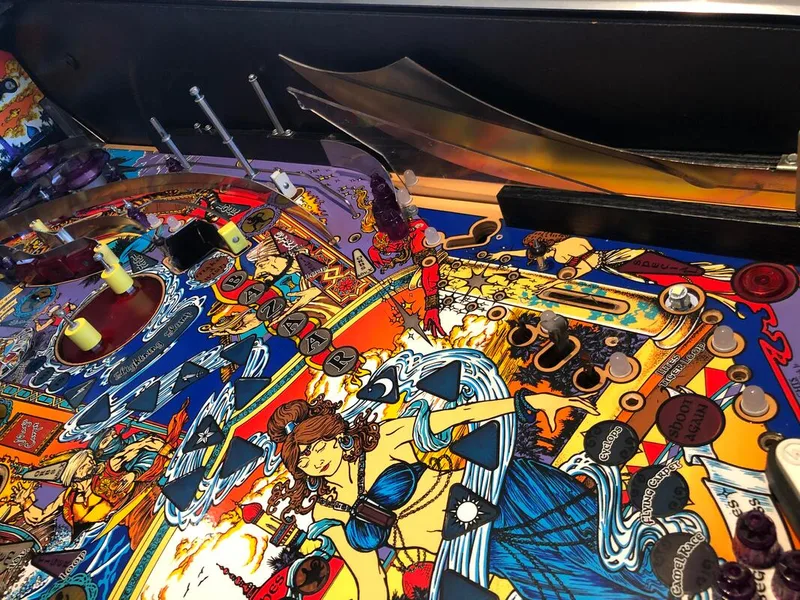
For some reason, Tales of the Arabian Nights has no recess in the playfield for the ramp to sit in, so the ramp sits on top of the playfield surface. The top edge of the ramp sits a few millimetres above the playfield, which the ramp flap covers. There is a noticeably steeper incline over this ramp flap compared to other WPC games where the ramps sit in the recess. I have no idea why Williams didn't recess this ramp, because it does result in air balls from time to time if the ball is heading towards the ramp at high speed. Just a bad design choice, I guess. While this ramp did have a flap, it was ripped on one corner from where balls had impacted it. It was actually sitting in mid air, not flush with the playfield, which is why balls were able to hit it.

Ramp flap with damaged bottom corner.
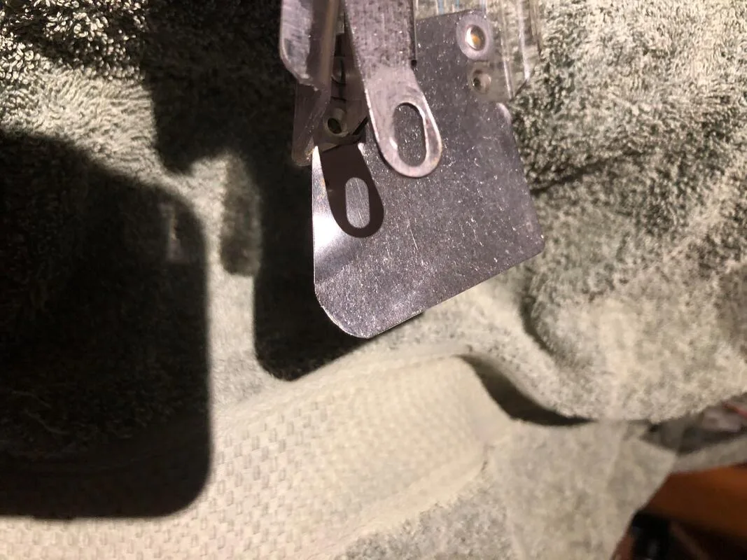
Ramp flap after cutting.
The solution was simply to cut the ramp flap back so it was rounded and smooth. You could probably do this with tin snips or similarly sharp scissors as the ramp flaps are quite thin steel. However, I like doing these kinds of cuts with a small Dremel tool or similar rotary cutter as this gives you some better control over the cut. A bench grinder would probably be an acceptable way to do it, too. Once the cut had been made, I used an abrasive polishing attachment for the Dremel to take out the burrs and sharp edges on the corner.
While the design of the ramp area (with no recess) meant that the flap could sit in midair, I applied some double-sided tape to the underside of the flap to stick it to the playfield. This will keep it there and out of the ball's way in future.
Fixed ramp flap reinstalled and adhered to the playfield.

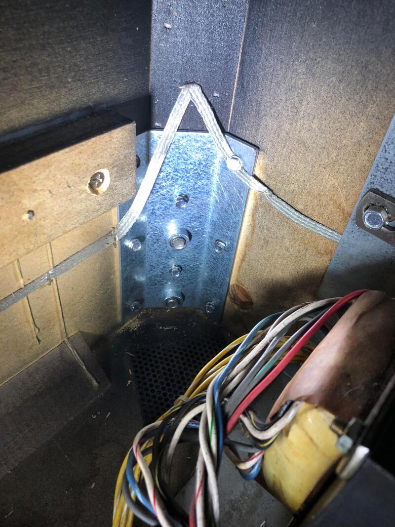
This machine was horrible to pack up and move to the workshop for servicing, as all eight leg bolts were secured with some kind of threadlocker. Some of them could be extracted with a bit of force, but one bolt at the rear of the machine could not be removed no matter how hard we tried. We ended up having to pull and twist it with mutigrips, and bash it out from the other end with a mallet. Not fun!
So, once we got the machine to the workshop, replacing the leg bracket (RTBB, Mr Pinball, PSPA) was one of the first things we did. Note that you can now buy "new and improved" leg brackets that have twice as much thread as the old ones. Get these whenever you can as they give more stability to the leg.
Installation is very simple, just unscrew the leg bracket (six screws) and replace. There will be a grounding strap attached to the leg bolt, so make sure it is screwed to the new leg bolt, too. There are two important tips that make installing the new bracket easier. First, don't install it upside-down! Otherwise you'll be trying to screw the bottom bolt in and you'll wonder why it's not going anywhere! Second, remove the playfield if you're working on the rear leg brackets. It is simply too much of a pain to get that far back into the cabinet with the playfield in the way to see what you're doing. Taking the playfield out makes this a much quicker and easier job. Unbolt the transformer if need be, as it can get in the way when working on the rear left bracket.

New leg bracket installed. Note the longer screw threads.
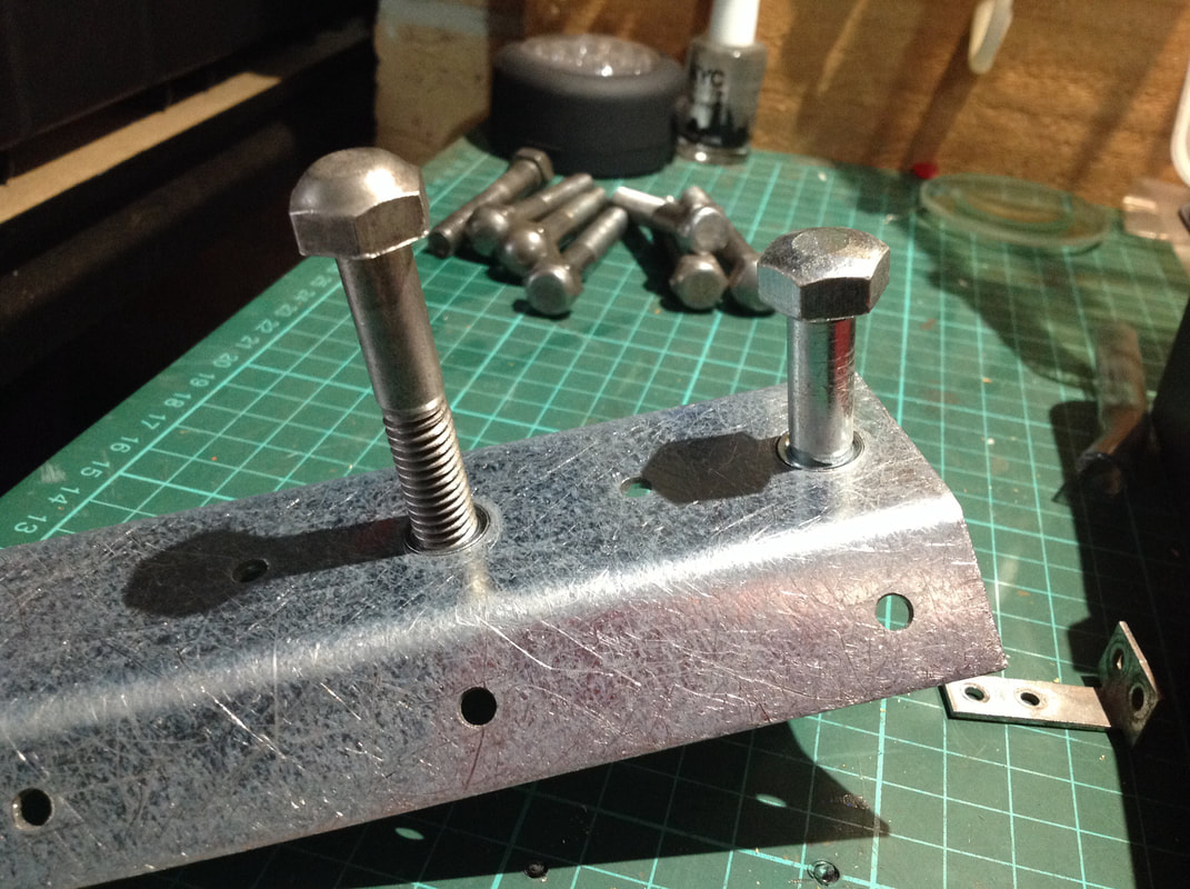
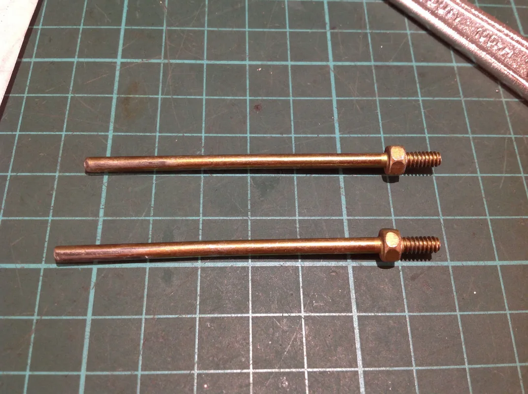
All of the leg bolts were thrown away as they were all fouled up with old adhesive. I have a big supply of leg bolts in my spare parts box for this reason - some machines will need to have all eight replaced! You can get leg bolts from all local pinball parts suppliers (RTBB, PSPA, Mr Pinball). Most sellers also offer them in black or gold finishes if chrome is not your preference.
I did discover something odd about "old style" or orignial leg bolts compared to "new style" replacements. The replacement style bolts fit nicely into the new leg bracket, but the original bolts did not go further than a few threads in. I've got no idea why that is the case, but it would appear that the thread on the new style leg brackets is ever so slightly narrower than the originals. So it may be a good idea to buy new leg bolts whenever replacing a leg bracket to ensure you have compatible bolts.

Original leg bolt (left) and new replacement (right) being installed into a new leg bracket.
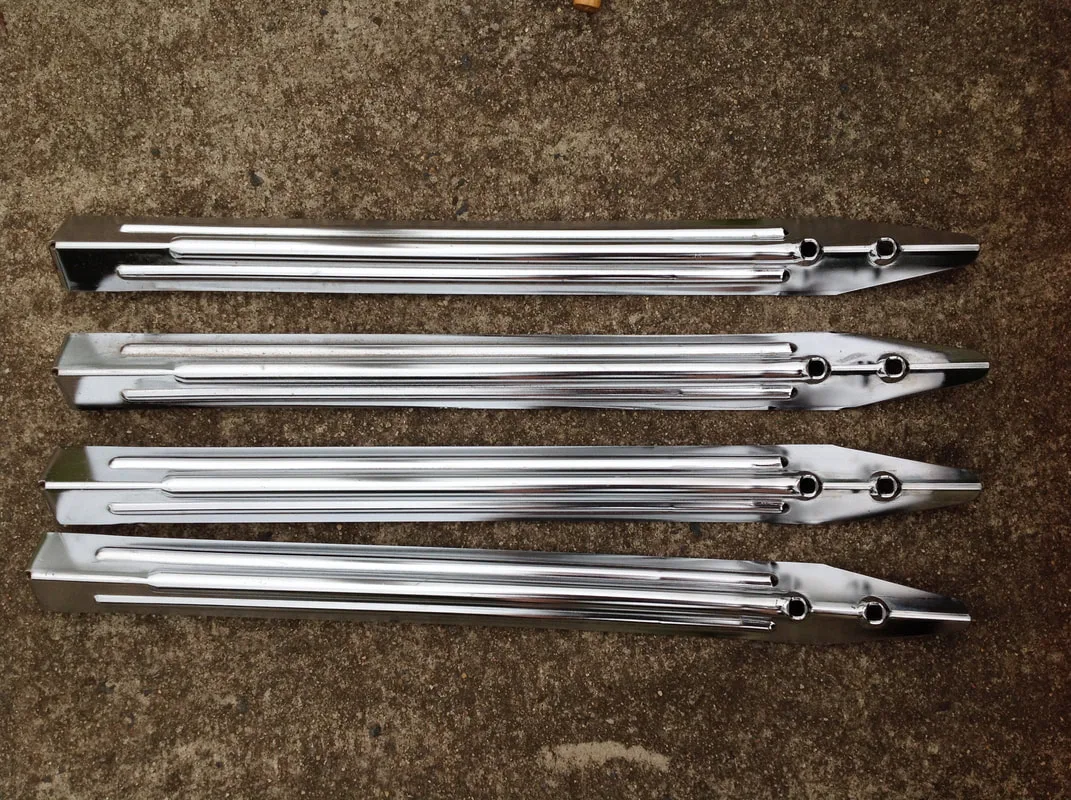
Once the leg brackets and bolts were sorted out, it was finally time to work on the legs themselves. These legs were in average condition, with a large amount of rust on the inside edges.
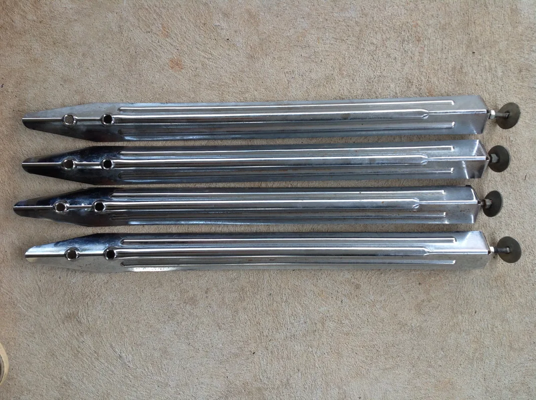
Legs in original condition; front.
Legs in their original condition; rear.
The legs went into a vingear solution overnight to mobilise the rust. Usually when I remove the legs from the vinegar, I give them a scrub with a nylon brush. This time, I wanted to try an easier option. I had just bought a tiny pressure washer unit for $70 (Supercheap) and it did a great job on the driveway, so I figured it would also make quick work of any rust residues left on the legs. And it did! Much faster than scrubbing them with a brush. Not quite as controlled, but definitely a good way to clean them off initially after a vinegar bath. They didn't really need any further scrubbing after a pressure wash.
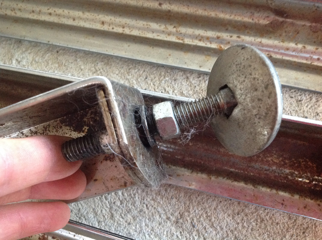
There was one other item that needed fixing on the legs - the captive nuts on the base of two legs. These nuts were loose, so the leg levelers were flopping around all over the place. Luckily, my good mate Darren is pretty handy with a stick welder, so I brought them over to his place to fix up. Two to three blasts of weld on the base of each leveler secured them nicely, and they were ready to use. If you're not too clean with your welding, be sure to weld the underside of the legs, as you'll never see them.
A loose captive nut thread.
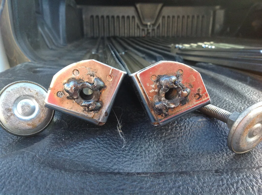
Captive nuts welded back in place.
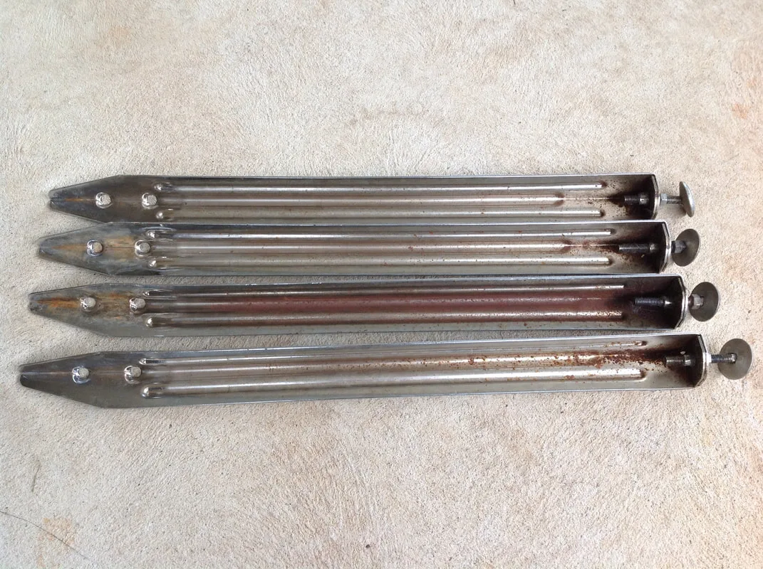
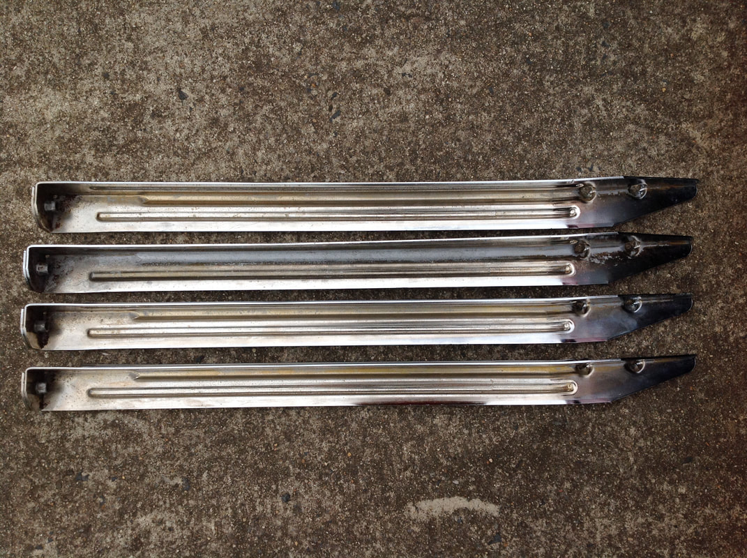
The final step was to shoot a couple of layers of clearcoat over the top of the legs to seal in the finish and prevent any future rust. This was especially important on the rear side, as the rust had eaten away most of the finish and had left the bare metal behind on a couple of these legs. Without a protective coating, rust would take over again in no time. Otherwise, the legs are looking good again!
Legs after derusting and cleaning.
Rear side after cleaning, but before clearcoating.
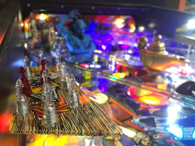
Even after a good clean, it was still having issues. When looking at the assembly from above the playfield, you can see the individual post spikes (part no. 02-5248) in their resting position. I noticed that some of them were not centred in their holes. When I activated the assembly by hand, I realised that some of the post spikes were actually quite bent, and it was these spikes that were binding on the playfield and preventing it from retracting. These spikes get hit by balls, sometimes at speed, so over time they will get bent out of shape and require straightening.
Post spikes from the shooting star assembly. Bottom post is significantly bent.
The other issue was related to the other (left) shooting star assembly. This one raised and lowered as expected, but when activating the plunger manually I found that there was a lot of resistance when the cage was pushed upwards. This appeared to be due to bad playfield design. The left cage is situated in close proximity to the rubber ring above and to the left of the outlane. It's so close that the rubber ring actually rubs against the post spikes when they raise and lower. Now, it doesn't put enough pressure on them to prevent movement, but it could exacerbate any other issues the assembly might be having. Potentially, thinner rubber rings would alleviate this issue, but I don't have any that are thinner than normal. For now, this doesn't seem like a big issue, but definitely one to keep an eye on.
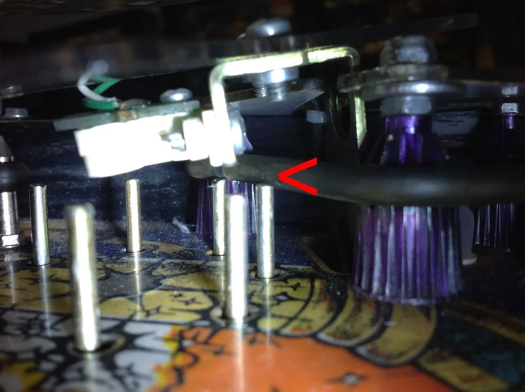
Cage post spikes impacting a nearby rubber ring.

Electrical tape wound around the trough assembly.
Rubber grommet installed. Much cleaner!
Another small issue was that balls would occasionally get stuck in the ball trough. Often, the balls would be in the trough, but would not move forwards towards the trough eject plunger. At first I thought this was due to divots in the trough, however I filed these down and saw little improvement. It was only after I put two balls back into the trough and realised that the balls were still not moving forwards at all (i.e. ball positions 1 and 2 were empty, even though there were four balls in the trough), that I realised the problem was the balls themselves. The balls had magnetised, and were holding onto each other so they would not move down the trough. The only remedy to this was to replace the balls, preferably with carbon balls which are more resistant to magnetism (RTBB).
Trough divots which I believed were the original cause of ball hangups in the trough.
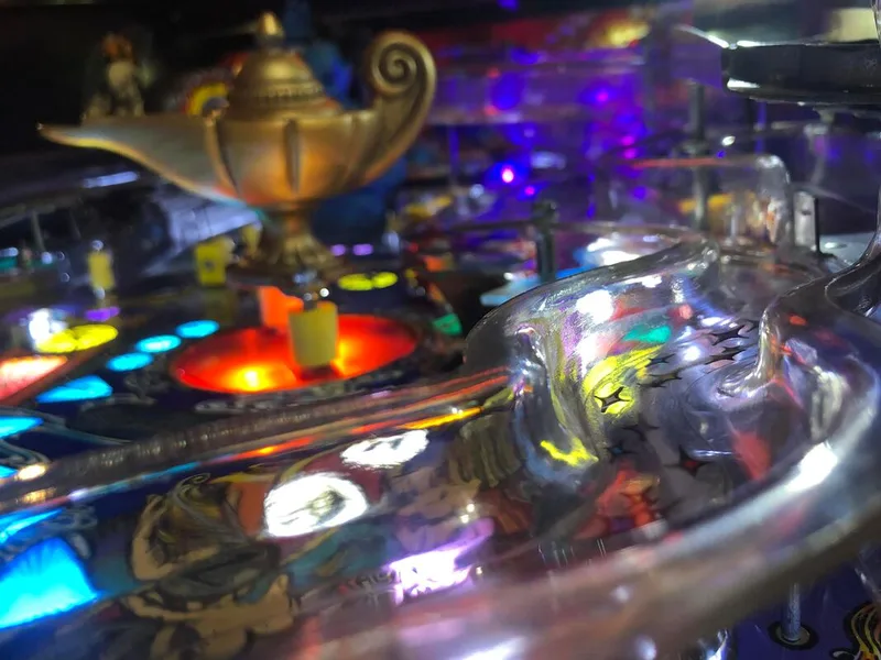
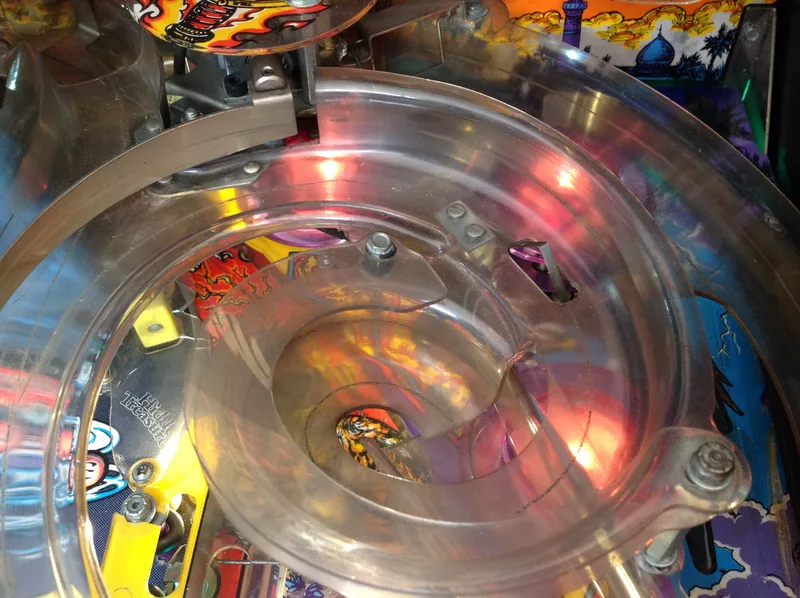
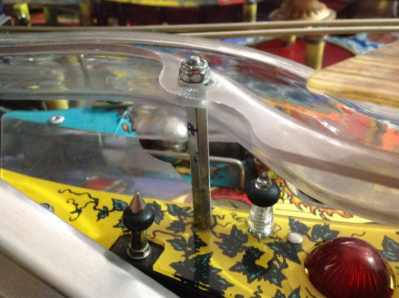
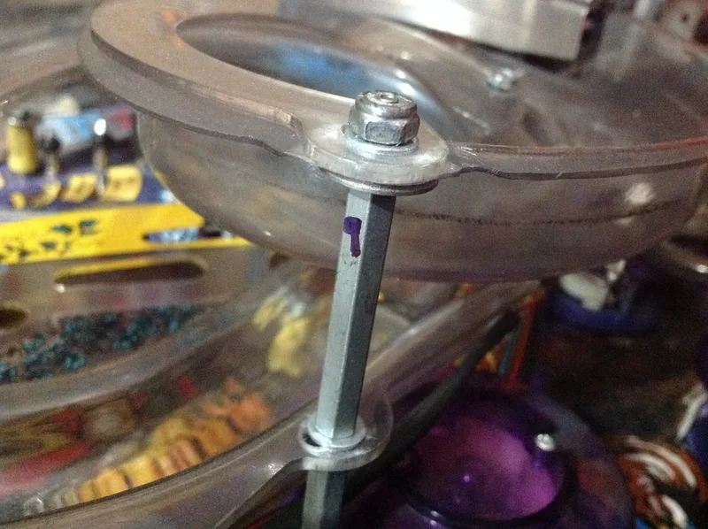
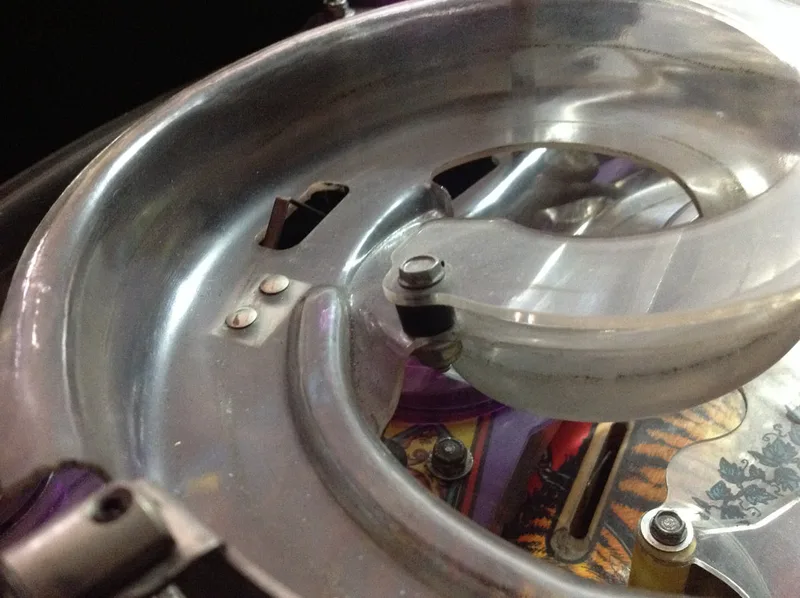
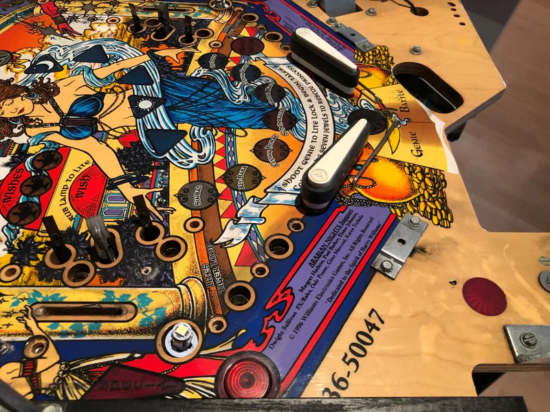
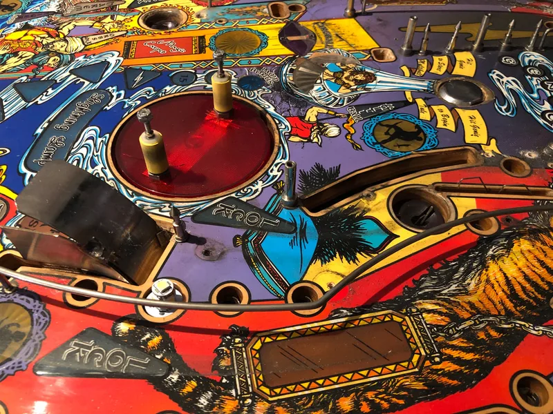
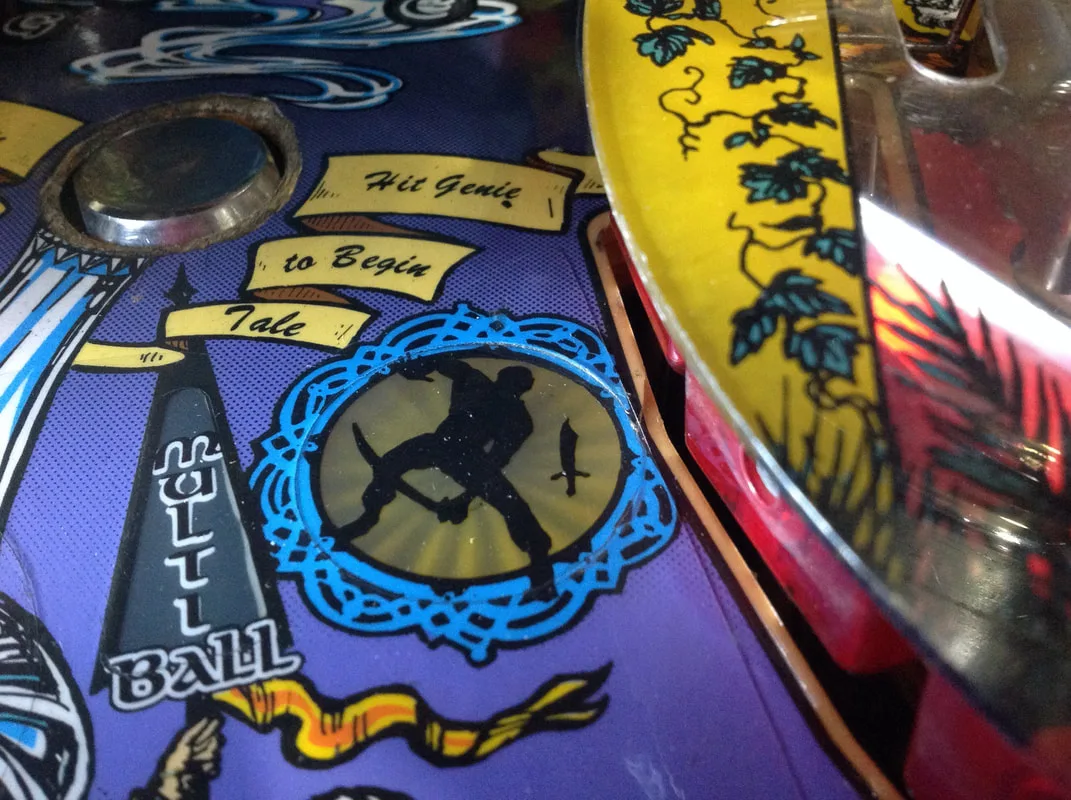
The process for reassembly is just disassembly in reverse; nothing in particular needs to be done differently. One particular item may need a fair bit of adjusting. That item is the spinning lamp assembly. The platter can be raised and lowered to ensure balls don't damage the playfield edge. This can be achieved by loosening the white collar underneath the assembly, then rotating the main shaft (silver) clockwise to raise the platter, or anti-clockwise to lower it. Ideally, you want there to be no difference in height between the playfield and the lamp platter. You may want to make the platter ever so slightly higher than the playfield to prevent ball hang-ups on the interface between the platter and playfield. This is especially useful if the playfield edge is a little worn surrounding the platter, making it more susceptible to "catching" balls.
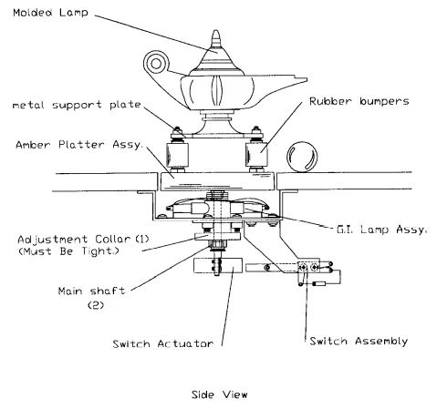
Excerpt from the manual indicating adjustable items (1 and 2).

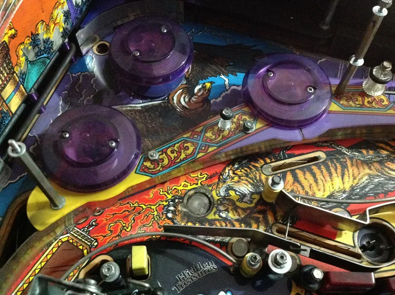
There is a rubber ring located at the rear of the playfield underneath the back panel (behind the pop bumpers). This one is easy to miss when reassembling the playfield, but if you forget to replace it, it's impossible to change it out without taking the top half of the playfield apart again! Even worse is if you take this rubber ring off, but forget to put it back on. You'll be losing pinballs into the cabinet whenever you shoot for the pop bumpers!
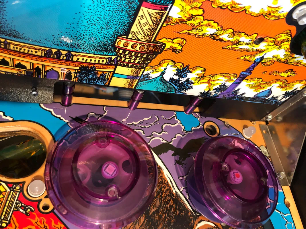
Don't forget to replace the rubber ring on these three posts!

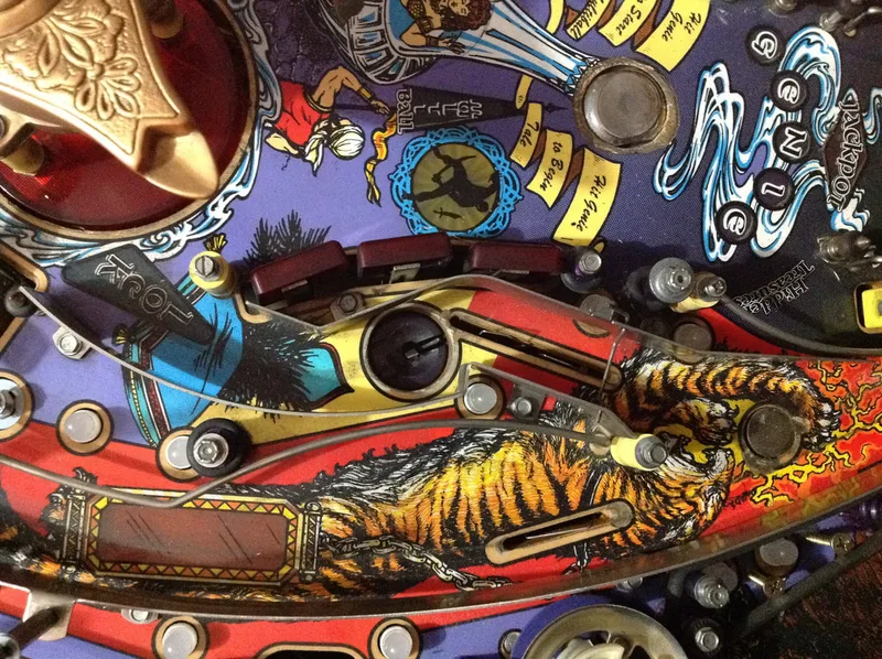
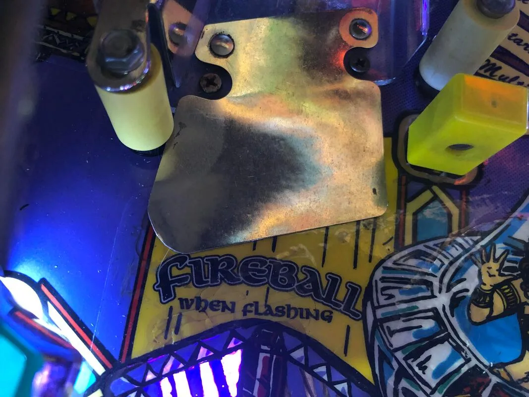
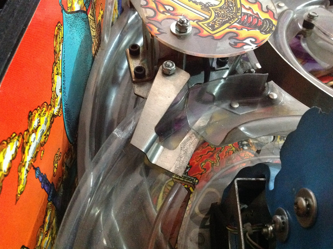
There was one playfield part which stumped us when it came to putting the game back together. This metal part was originally attached to the swirl ramp and connected it to the left ramp assembly. It didn't quite fit properly when we put the ramps back together, and we figured out that it was not supposed to come from this area at all. In fact, it sits on the left ramp adjacent to the fireball magnet, and protects the ramp from ball movement when it is sucked into the magnetic field of the fireball magnet.

This is not the correct location for this metal part!
All of the rubber rings were replaced on the playfield. Surprisingly, Tales of the Arabian Nights has very few rubber rings. Most of the rubber parts on this machine are post sleeves (part no. 23-6556) or small rubber grommets for mini posts (part no. 23-6694-1). Note that the rubber ring behind the pop bumpers (mentioned above) is not listed in the manual. You can use a ring 2-3" in size for that one. In total, there are about eight rubber rings, excluding flipper rubbers. We used black rings on this game as black seems to fit the colour scheme of the playfield a bit better than white. Other than that, new black flipper rubbers were installed onto the clean flipper bats, and a new plunger tip was also used.
The LEDs which were originally pulled from the machine were a mishmash of weird colours and types. All of the general illumunation lamps were replaced with frosted cool white LEDs. The cool colour temperature appears to work well with the purples and blues on this playfield, and the playfield looks much crisper as a result. Flashers were also replaced. All flashers were white, with the exception of a red flasher in the genie assembly to make his eyes glow red.
The last thing that was done was an upgrade of the game ROMs to the latest versions. This included the audio and game ROMs. One advantage of the latest game ROM (version 1.3) is that a new adjustment was added which allows you to increase the strength of the magnet throw when the ball is released from the magnet after a mode is started. Sometimes, the ball will not be thrown much at all, causing it to dribble down the centre of the playfield and straight down the middle. The solution to this is to increase the throw strength, which should send the ball flying around the magnet before it comes down the playfield, hopefully in a direction that is not straight towards the middle!
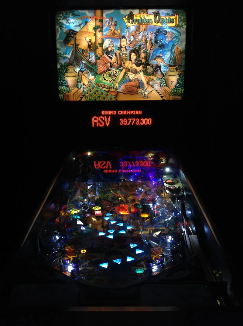
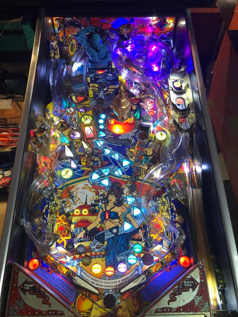
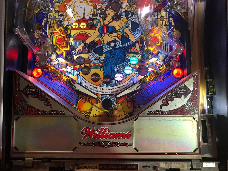
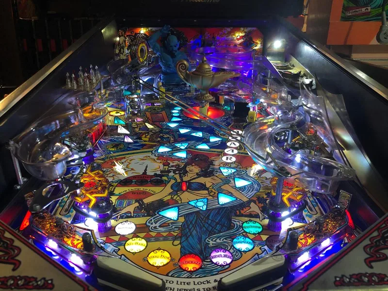
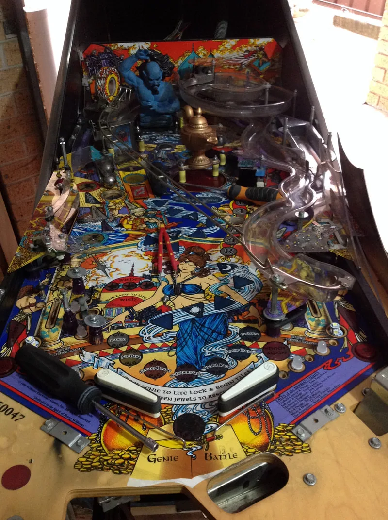
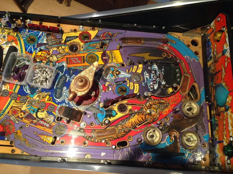
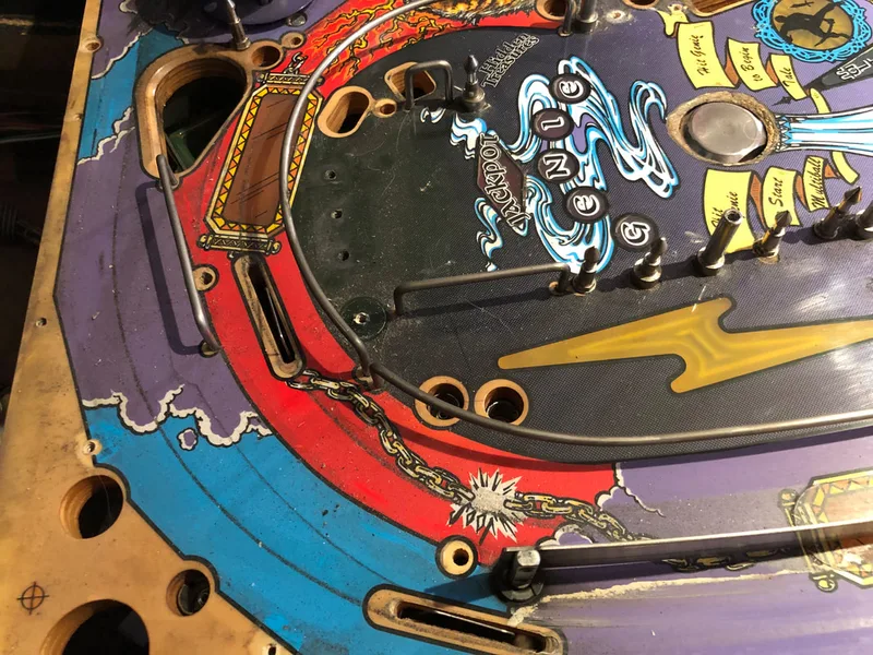
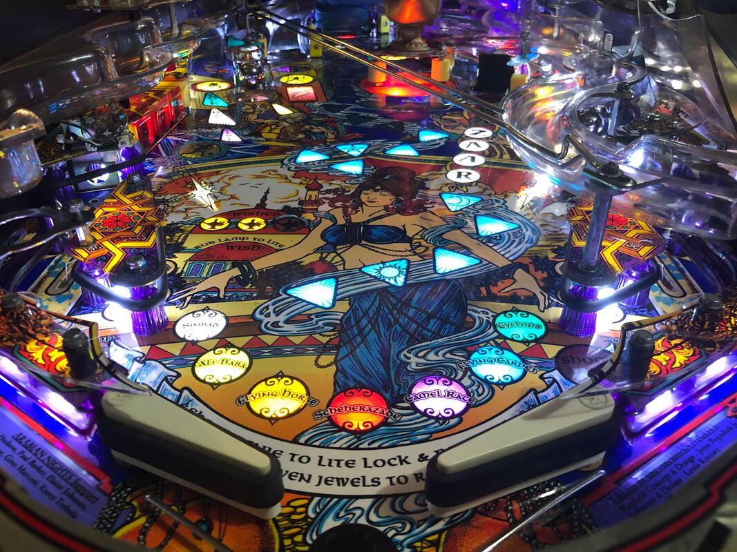
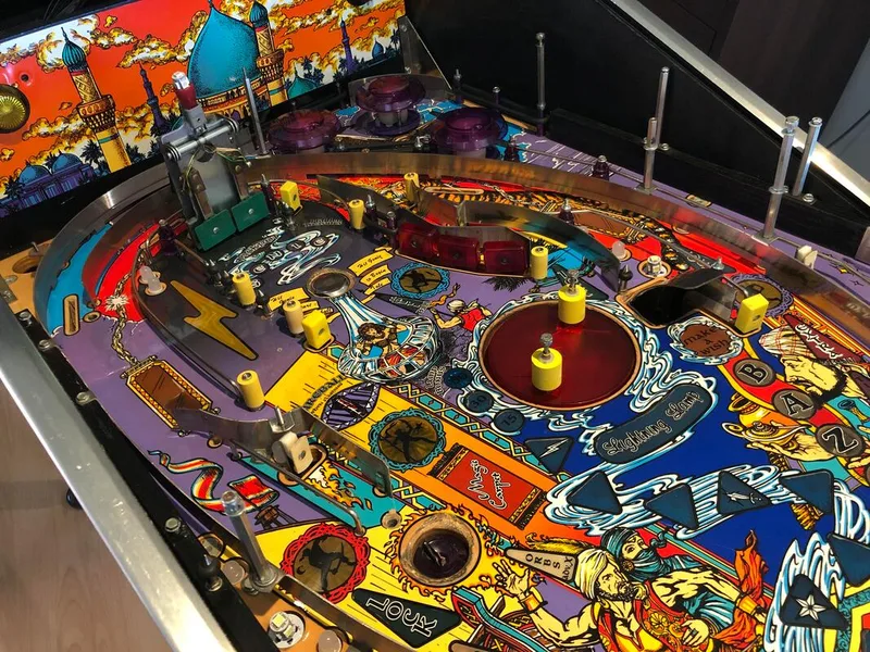
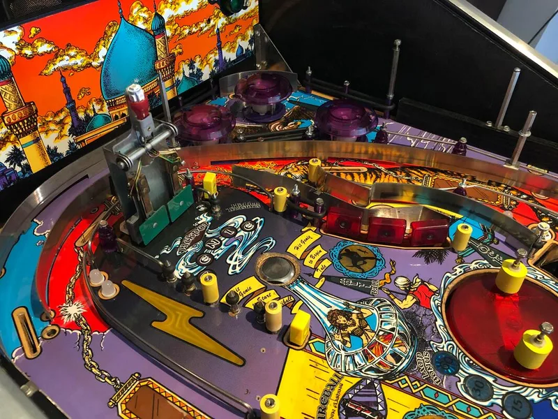
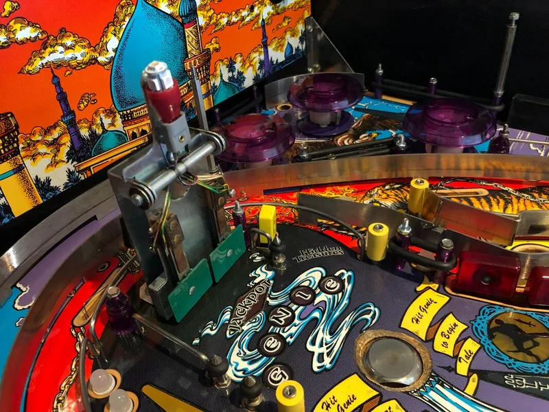
Below are a few images of the partly assembled playfield after cleaning.

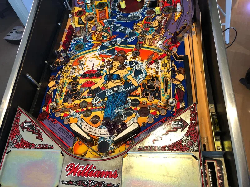
Getting to play Tales of the Arabian Nights got me to understand the strong feelings a lot of people have towards it. It really is a beautiful game when repaired and cleaned. I can sit and watch the game in attract mode for hours. The display animations are also beautiful. I love the animation that plays when you are granted a wish (same as the match sequence animation). The ramp shot is also very satisfying to make. Hitting it just right will send the ball all the way around the swirl ramp and up around the genie. But a slow or poorly angled shot will lose momentum and either drop into the pop bumper area, or drop into the right orbit, and fall back towards the slingshots. I love that a single ramp can send the ball in so many different directions.
However, a lot of people complain that the gameplay is one-dimensional. After playing the game for a while, I tend to agree. Most of the modes revolve around hitting the same golden symbol shots around the playfield, which number five in total. A couple of modes require you to hit other targets (i.e. captive balls) but that doesn't do much to break the repetition. The wizard mode is the same deal, requiring you to hit the golden symbols first to kill skeletons, and then to defeat the genie himself.
So, while the playfield, sound package, and display animations are all top notch, the rules let the game down somewhat. That's not to say it isn't fun to play. It absolutely is. But it probably won't engage more serious players for too long once they get a grasp of the rules and dial in the golden symbol shots.
That said, restoring this Tales of the Arabian Nights was a great opportunity, particularly to practice some difficult playfield repairs. This machine required a lot of work, and I had to practice most restoration skills that I know from board work, to playfield touch ups, to general technical troubleshooting. It's great to know that brand new reproduction playfields, plastics and other parts are available for this game to keep it running well into the future.