|
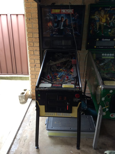
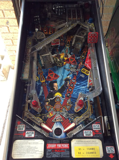
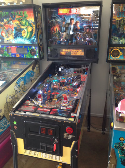
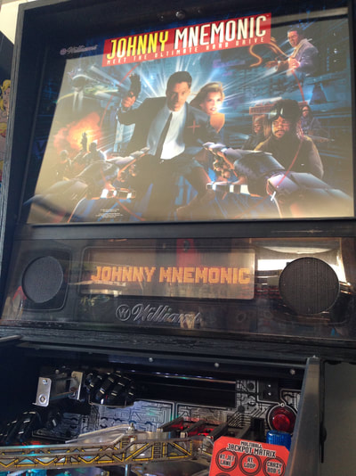
Johnny Mnemonic (Williams, 1995) was another machine from our pinball road trip. Fiona and I had tackled all of our previous restorations at a leisurely pace. We'd generally start tearing a machine down for cleaning, clean and repair the parts as necessary, and then put them all back together whenever we had a chunk of spare time. As of late, we had not had that much spare time to devote to pinball. Our last restoration of Doctor Who (Bally, 1992) took us several months because we were so busy with other things going on. It's a little frustrating to have a machine sitting in pieces for so long, not being played. With this restoration, we decided to try something different. We both freed up our Easter long weekend and devoted it entirely to restoring Johnny Mnemonic from start to finish. So come Friday afternoon, we turned our phones off and got to work. Just like the restored machine, our work this time around was fast and furious. Initial condition report (click on sections below to view details) Cabinet
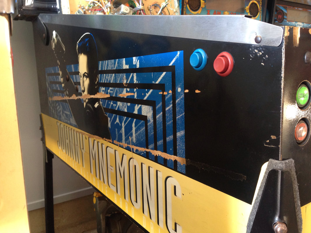
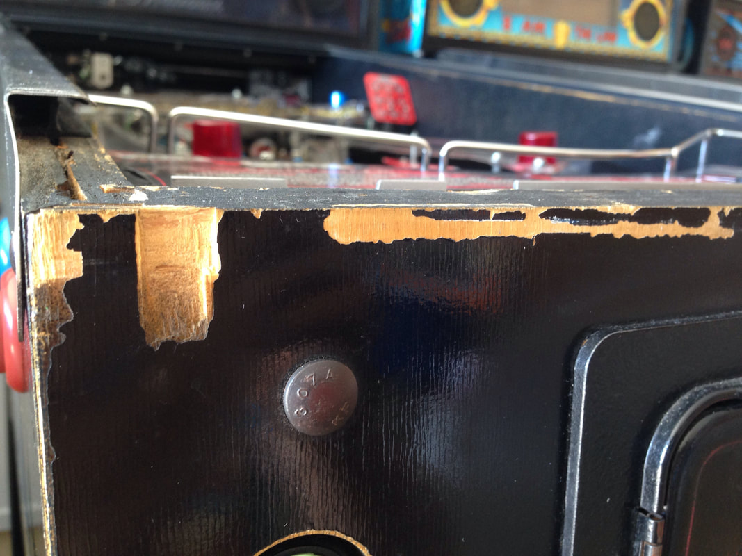
Poor condition overall.
Above playfield
Poor condition overall.
Under playfield
Average condition overall.
Electrical
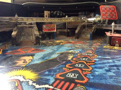
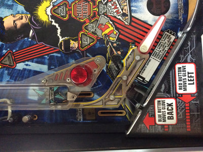
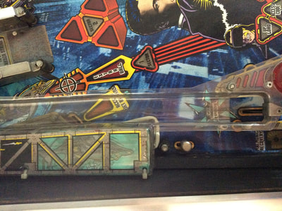
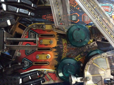
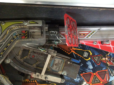
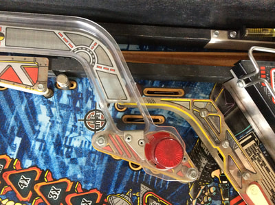
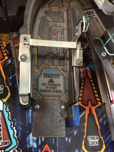
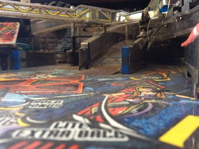
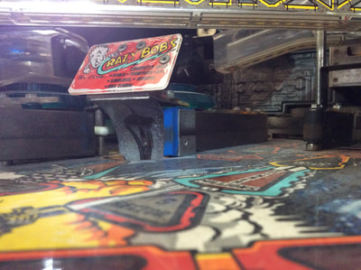
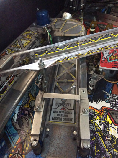
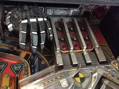
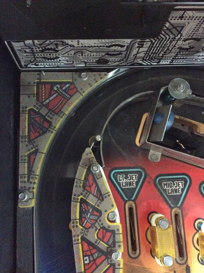
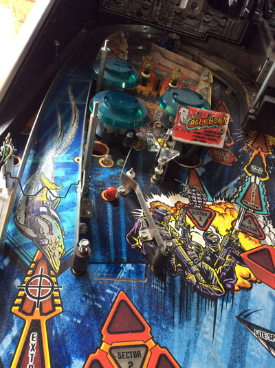
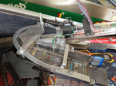
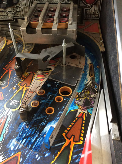
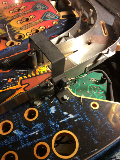
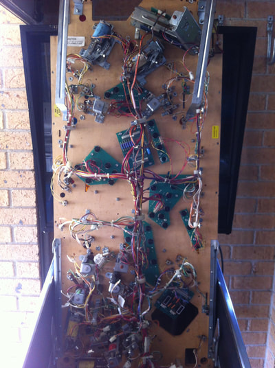
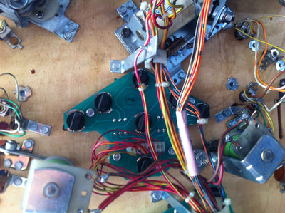
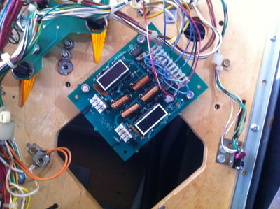
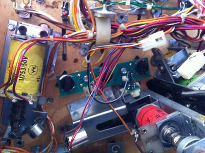
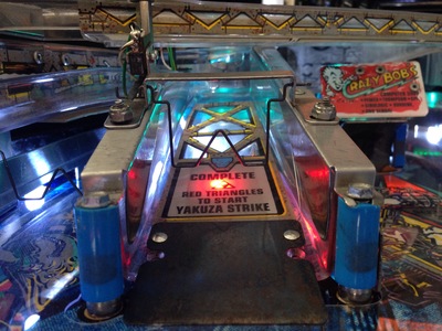
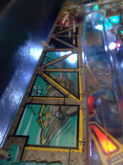
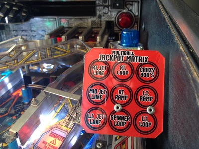
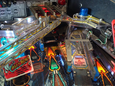
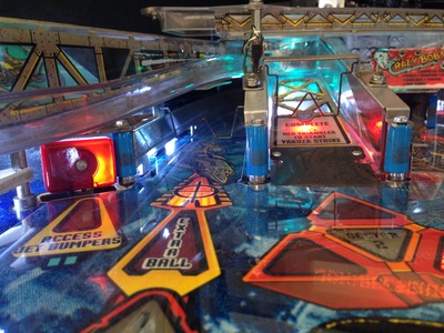
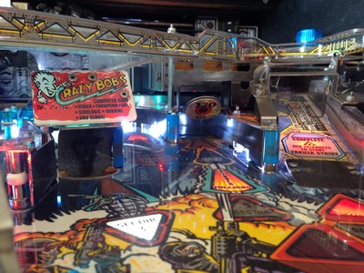
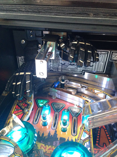
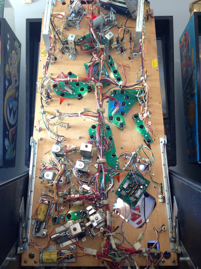
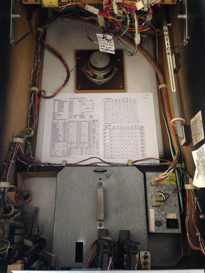
Frustratingly, the Cyberglove was working when I first bought the machine, but had since decided to stop working for no apparent reason. Just as well I had planned to rebuild it completely anyway. After assessing the machine, Fiona and I figured it was a good candidate for a weekend restoration as most of the machine could be cleaned and repaired with parts we had on hand and without too much difficulty. So, we got stuck into it. Disassembly Johnny is a simple machine to take apart, with the exception of the Cyberglove assembly, which is a royal pain. The rest of the playfield, however, is quite simple. Most of Johnny's gameplay focuses on ramps, orbit shots, and the spinner lane. The first things you'll need to remove are the ramp assemblies which cover most of the playfield. After that, there's not much left. The Cyberglove is best cleaned and serviced separately to the rest of the machine. We tackled the playfield first, then fiddled with the Cyberglove later. The underside of the machine is actually very bare - there's not much under the playfield except for the rearmost section. The front two-thirds are just made up of lamp boards, lamp sockets and a couple of switches. Here are some images of the machine and disassembly. After disassembly, the game went through my standard restoration process to get it playing and looking like new. During the restoration process, I dealt with a number of issues, described below. Tips & Troubleshooting (click on sections below to view details) Cyberglove rebuild
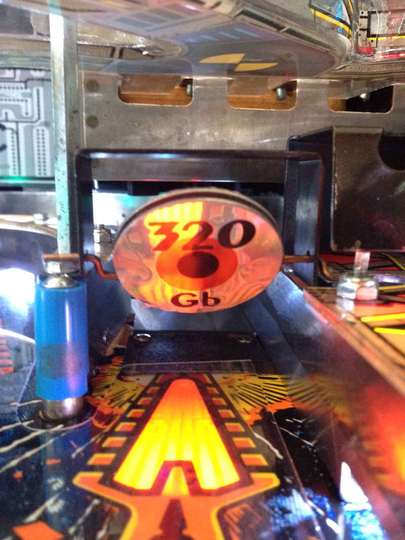
One of the coolest parts of Johnny Mnemonic is the Cyberglove at the rear of the playfield. It grabs balls kicked up from the trough under the playfield, carries them in mid-air, and drops them into the pop bumpers or the matrix at the top right hand corner of the playfield. It's really cool to be able to control the hand and move the ball around wherever you want.
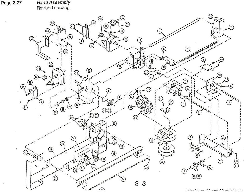
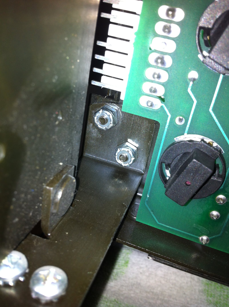
It's all fun and games.... until it breaks. And it ALWAYS breaks. If your Johnny Mnemonic hasn't been restored or cleaned before, you will need to rebuild the Cyberglove assembly from the ground up. My Cyberglove actually worked pretty well when I bought the game. The only issue was that it screeched like a banshee when moving. It was definitely in need of a good teardown and service. Before I dove into it, I began having flashbacks to rebuilding the Doctor Who Time Expander mini playfield. The Cyberglove and the Time Expander are both pains in the ass. They are both really cool playfield features, but absolutely horrible to clean and maintain. Thankfully, the Cyberglove is a little easier to work on than the Time Expander in my opinion. The assembly is a little simpler, and requires less adjustment to get it working right. Thankfully, someone has already gone to the trouble of creating a fantastic guide for disassembling and repairing the Cyberglove. Check out Quinn Dunki's Cyberglove rebuild article, as well as a bunch of her other repair articles relating to Johnny Mnemonic. Well worth a read in preparation for rebuilding your own Cyberglove. Moreover, be sure to have a copy of the Cyberglove assembly diagram from the manual. Most copies of the manual do not actually have part numbers identified on the assembly diagram, but luckily you can view an updated version of the diagram in the 1996 Williams Red Sevice Bulletin Book. I removed the entire back panel assembly from the game and worked on it piece by piece. It basically breaks down into three components: the cyberspace matrix assembly (part no. A-20447), the Cyberglove itself, and the back panel with the X and Y (left-to-right and forward-and-back, respectively) movement motors attached to them (part no. A-20500). Attack each section piece by piece, and the whole rebuild process starts to look a lot more manageable. To get the back panel off, undo the lock nuts under the playfield, and undo all of the Cyberglove assembly connectors while you're there. Then, lower the playfield into the first service position. You'll need to unscrew two plastics - the one at the top right of the playfield and the one at top left. They're attached to the back panel and won't come with it! At this point, you're ready to lift the back panel out of the game. If you like, you can detach the cyberspace matrix from the back panel and leave it on the playfield, but I found it easier to lift the entire assembly out. Now, clear your workbench, because you'll need a lot of space when this is all in pieces. You will probably find that it is either not possible, not necessary, or not desirable to take the assembly completely apart. Most parts can be refurbished while they are loosely connected to the rest of the assembly, and in my case, I wasn't able to separate all of the parts anyway. Work around the mess as best you can, but disassemble everything to a point that it can at least be cleaned and inspected. I tackled the rebuild by breaking it down into the following tasks:
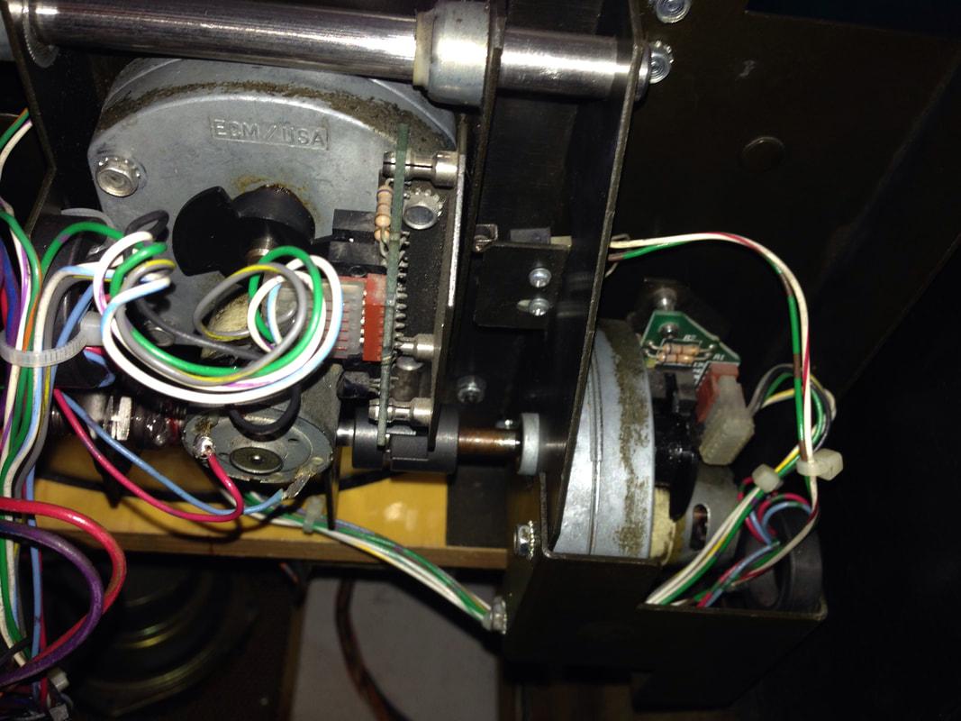
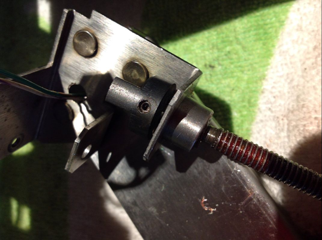
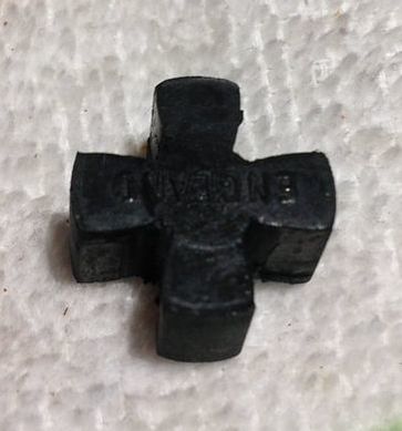
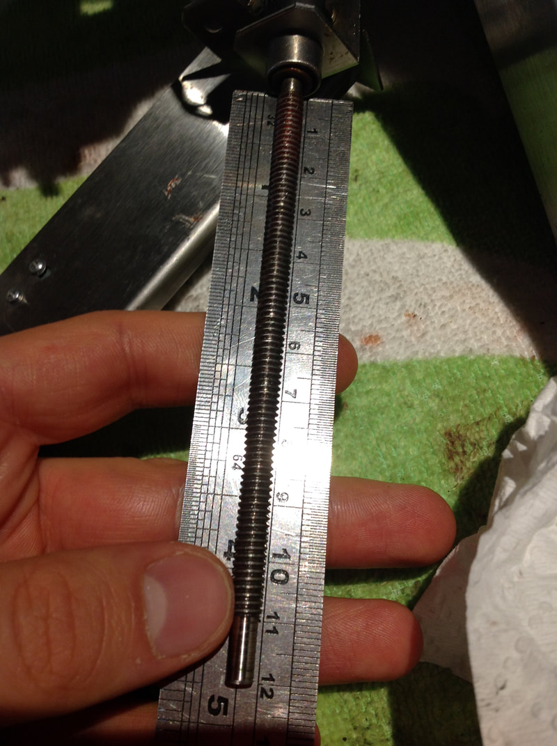
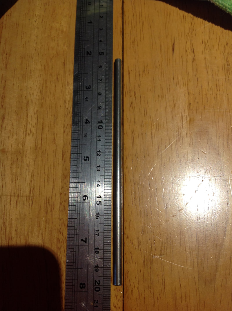
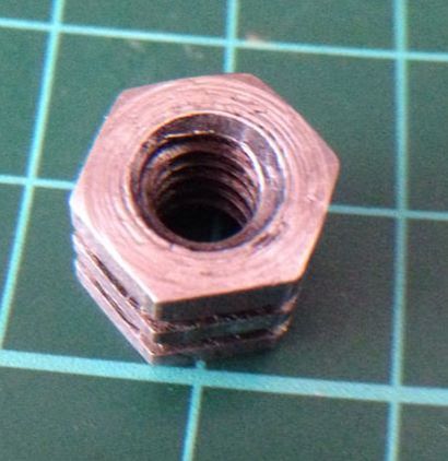
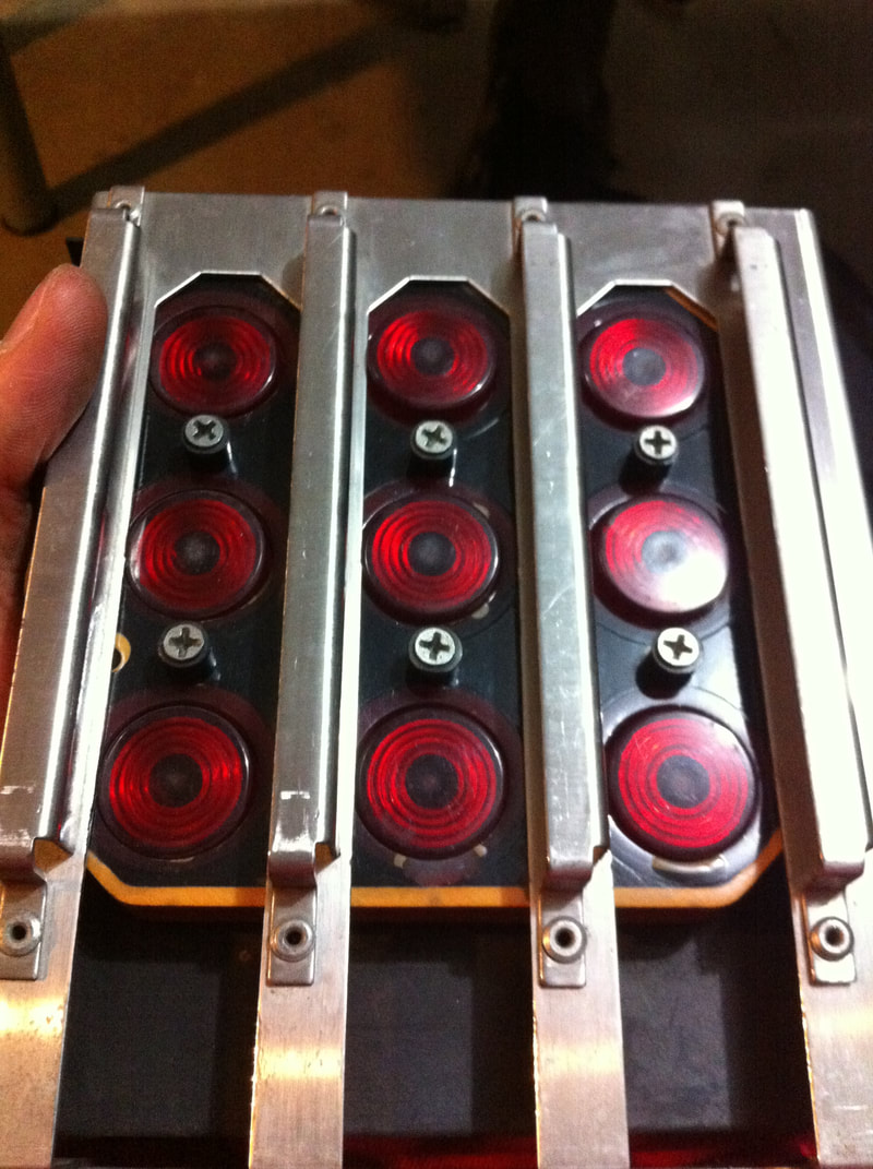
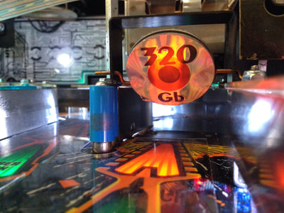
The Cyberglove is driven by two motors mounted to the back panel assembly. Each of these motors is paired to an encoder board (part no. A-20533.1), which controls the Cyberglove's X and Y axis movement. Cracked solder joints on these boards are a common source of issues, so check them to make sure they're 100%. Each board also has a pair of opto switches to keep track of hand movement; give these a clean to ensure good operation. My encoder boards were in good nick and just needed a clean. Next up are the two twelve-volt motors and gearboxes (part no. 14-8025). Both of them need to be disassembled and the gearboxes regreased, if the old grease is old and sticky. I removed all of the old grease in both gearboxes and replaced it with Nulon Extreme Performance Grease. I was initially disappointed because even after regreasing them, the motors were still quite loud. After watching some videos of other Cyberglove assemblies, it would appear that these motors are naturally quite loud anyway. Firebird pinball has an excellent blog post covering cleaning and regreasing the hand motor gearboxes. At this point you should take apart the X and Y rod assemblies as far as you are possibly able to. That is, remove the rods and the nuts that travel on them. I had some difficulty here. The X rod (part no. 02-5207) was easy to remove as it could be uncoupled from one side of the back panel and pulled away. The Y rod (part no. 02-5209) is not so simple; you need to undo the spider coupling body at the end of the rod to remove it from the Y arm. Here is when I ran into trouble, because the grub screw securing the coupling body to the rod had been totally stripped and was more of a circle than a hexagon! I gave up taking it off and just cleaned the rod while it was still attached to the assembly. Damn whoever stripped this screw head; the coupling is basically permanently attached to the rod now! Also remember to inspect the spider couplings (part no. 20-10280) which connect the rods to their respective motor shafts. If these couplings are worn, you'll also get sluggish Cyberglove movement. Surprisingly, the couplings are a little difficult to obtain. Some local retailers stocked it at some point previously (PSPA), but almost everywhere is out of stock now. Pinside user fattrain managed to track down an equivalent part manufactured by a company called Lovejoy, Inc. in this thread. They even have an Australian distributor based in Sydney! The spider coupling (Williams part no. 20-10280) is equivalent to this Lovejoy part. Good to know that there is usually a solution to part unavailability! Clean the rods of any gunk and old grease that may have accumulated on them and regrease with your lubricant of choice. It's also important to check the rods for straightness, too. Bent rods will make the Cyberglove jitter. If either rod is damaged or bent, replacements are available for the X rod (Mr Pinball) and Y rod (Mr Pinball). My Y rod appeared to be a little bent, but I managed to straighten it out by compressing it with a piece of wood. Don't use anything hard such as metal for this, as you will damage the rod threads. The X and Y nuts (part nos. 02-5210 and 02-5211, respectively) are also extremely important for smooth functioning of the Cyberglove. If these parts are worn, and they are designed to wear as they are consumable parts, you will get slow, jerky or otherwise jammed movement from the Cyberglove. If you're a cheapskate like myself and you don't want to replace any parts unnecessarily, the X and Y nuts should still be replaced even if they show only the slightest wear. The nuts are made of softer metal than the rods and are designed to be chewed up over time rather than the rods, so they usually need replacement. So replace them before they become an issue! The X nut (Mr Pinball) and Y nut (Mr Pinball) are both available locally. I replaced the Y nut as the original one was worn. The X nut looked brand new with no wear, but I replaced it anyway. Most of the stress of the assembly is absorbed by the Y nut (due to the heavy magnet), therefore it made sense that it was more worn. After I rebuilt the X and Y assemblies and regreased each of their motors, I was weirded out by the fact that the Cyberglove wobbled a lot when tested on the bench. It was almost as if the Y rod was bent or the Y nut was worn, but I had just checked and replaced these, respectively. I tested the unit using a nine-volt battery while it was out on the bench. The video below shows the wobbling. This was a weird issue and I tried to eliminate the source of the wobble by checking and straightening the Y rod, replacing the Y nut, regreasing the motor gearbox and drive shaft, as well as supporting different parts of the assembly and trying to shift its weight. None of these solutions worked. Ultimately, I installed the assembly back into the game, only to find that it worked perfectly fine and the wobble was completely gone. I can only think of a couple of reasons for this. Either installing the assembly back into the game helped stabilise it, or the higher voltage supplied by the game (12 volts) as opposed to the low voltage from the battery (9 volts) helped smooth out the movement. Either way, it worked well when back in the game. The video below shows the assembly when reinstalled into the game. That's the hard stuff out of the way. Next is the cyberspace matrix assembly. There isn't much to this assembly other than the circuit board that sits underneath the matrix positions and houses the lamps and switches that detect balls in the matrix. The main task I wanted to accomplish here was swapping the incandescent globes out for LEDs. I used red flat-top 5050 SMD LEDs for this as they point straight up into the matrix holes. Test all of the switches while you're at it. Mine were all OK, so this assembly was cleaned and put aside. After that, the back panel assembly is pretty much finished. The last step is to clean up the Cyberglove itself and check the magnet. The magnet can be tested using the magnet test in the solenoid test menu. Also test the ball-in-hand switch in switch edge test. There is some good advice on testing these parts of the assembly in Williams Service Bulletin 85.
The ball-in-hand switch is a troublesome part of the Cyberglove. A lot of people have issues with it not activating properly or breaking, so some people remove it altogether. The purpose of the switch is to tell the game when to energise the magnet's hold winding (to hold the ball while the glove travels) instead of the high power winding (which sucks the ball towards the magnet core and grabs it in mid-air). So, in early ROM versions, this switch was necessary in order to prevent the magnet from overheating and burning out. Reportedly, ROM version 1.2 automatically swaps the magnet to the hold winding after a short time, regardless of the ball-in-hand switch's state. So, you can remove the switch altogether, but you'll have a permanent credit dot relating to the ball-in-hand switch. The is a workaround for this, if you want to uninstall the switch but want to get rid of the credit dot, but I would suggest it is more trouble than it is worth. My switch seemed to work well after a couple of minor adjustments as per Service Bulletin 85. New ones are available if you need to replace it altogether (PSPA), but they're pricey. They are slightly cheaper overseas (Marco Spec), so it may be worth combining it with a larger overseas order. When routing the wires for the Cyberglove through the back panel, ensure that they are clear of the X and Y drive shafts. Williams released another service bulletin to address the issue of incorrectly dressed wires causing short circuits and blowing fuses. I routed my Cyberglove wiring straight through the back panel, away from the drive shaft, and zip tied them to the wiring loom attached to the motor assembly. That way, they move with the Cyberglove and are less likely to be moved around by Cyberglove movement. Also make sure that the entire wiring loom behind the back panel assembly is clear of the drive shaft that moves the hand left and right. To test this, pull them playfield out into the first service position and put the game into hand test. Move the hand through its full range of left-to-right motion. Check that the wires don't snag or rub against the drive shaft rod, as this will eventually destroy the wire's insulation and cause short circuits. Keep in mind that there is not much space behind the back panel when the playfield is back in it's regular position, so the wiring loom needs to be neat and compact.
Fuse F104 blowing intermittently
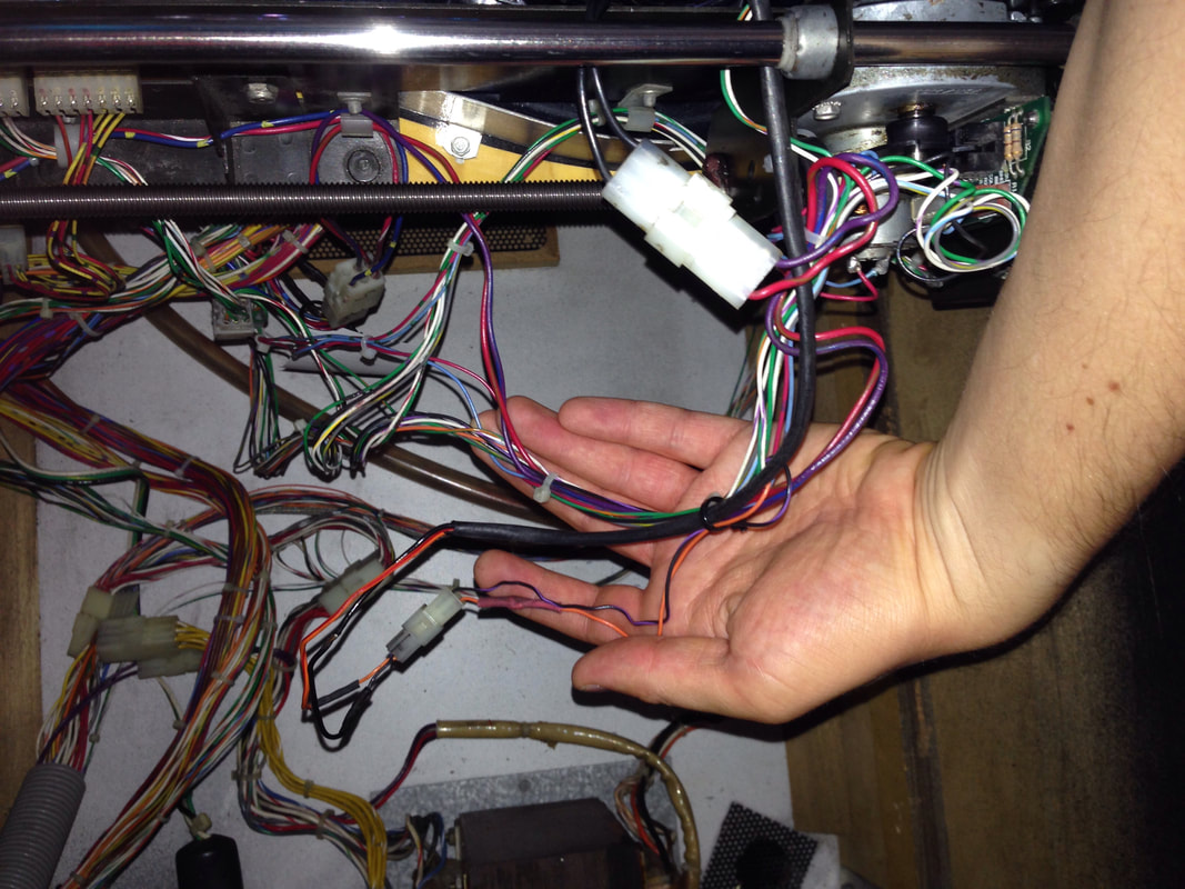
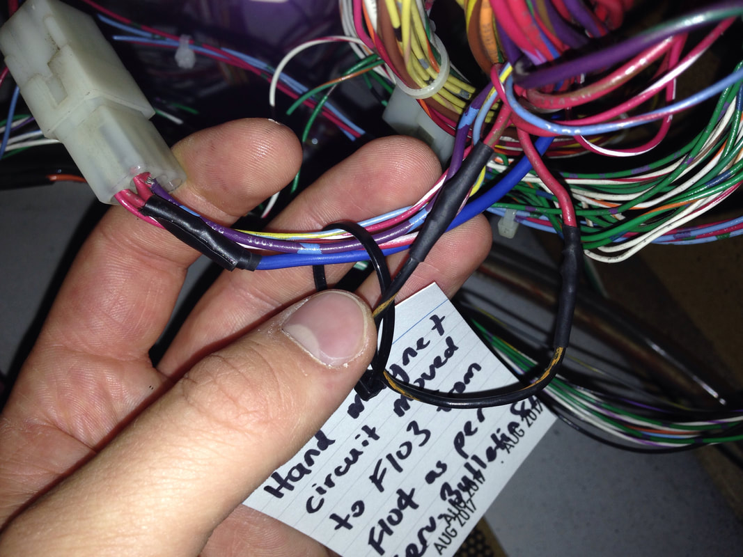
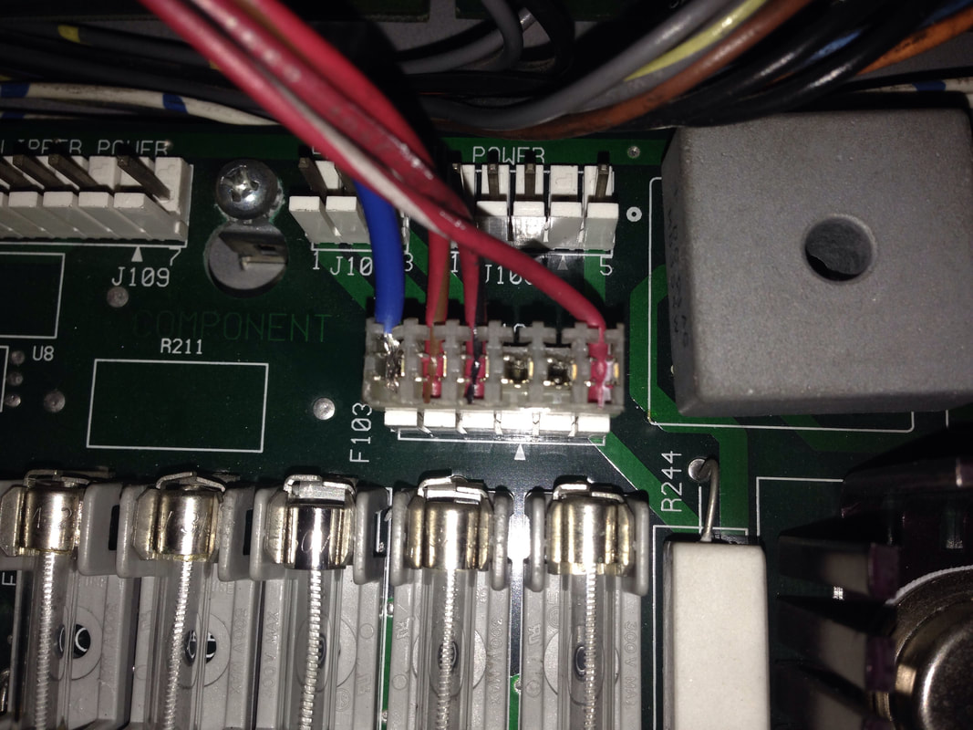
I was having some issues with fuse F104 blowing occasionally. It seemed to occur when the ball was shot into the Cyberglove, or while the Cyberglove was holding the ball. After looking into the issue, I found that this was a recognised problem due to the circuit protected by F104 being overloaded by the Cyberglove magnet. Williams actually released Service Bulletin 87 as a result of this issue and suggested rerouting the power circuit for the Cyberglove magnet from F104 to F103, which was otherwise unused on the game. So, I performed the modifications and everything seemed to be working perfectly.
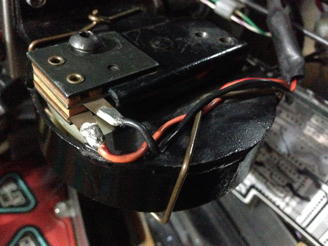
But in classic pinball fashion, the issue returned. I had just performed a modification designed to fix the exact issue I was having - what gives? I took the Cyberglove partly apart again and found the true cause of the issue. The wires from the magnet had been wrapped around the top of the magnet, and the hand on top of the magnet kept them nicely tucked away. The problem with this was that, when the hand was installed over the top of the magnet, the tabs on the ball-in-hand switch blades were digging into the magnet wires, causing a short. Whenever this happened, it would cause the fuse to blow. Moving them so they weren't near the switch tabs seemed to fix the issue for good. Hooray! So while I had performed the service bulletin modification unnecessarily, at least I've eliminated potential issues with the F104 circuit in the future. Cyberglove randomly dropping the ball
This was a tricky issue to track down as it was intermittent. Occasionally, the Cyberglove would drop the ball when it was moving to the matrix. It seemed to do this randomly - sometimes it would carry it all the way to the matrix, other times it would drop it within a couple of seconds. It seemed to happen a lot when moving the hand towards the rear of the cabinet, too. Weird. It seemed like an issue with the ball-in-hand switch, as this is what controls power to the magnet in the Cyberglove.
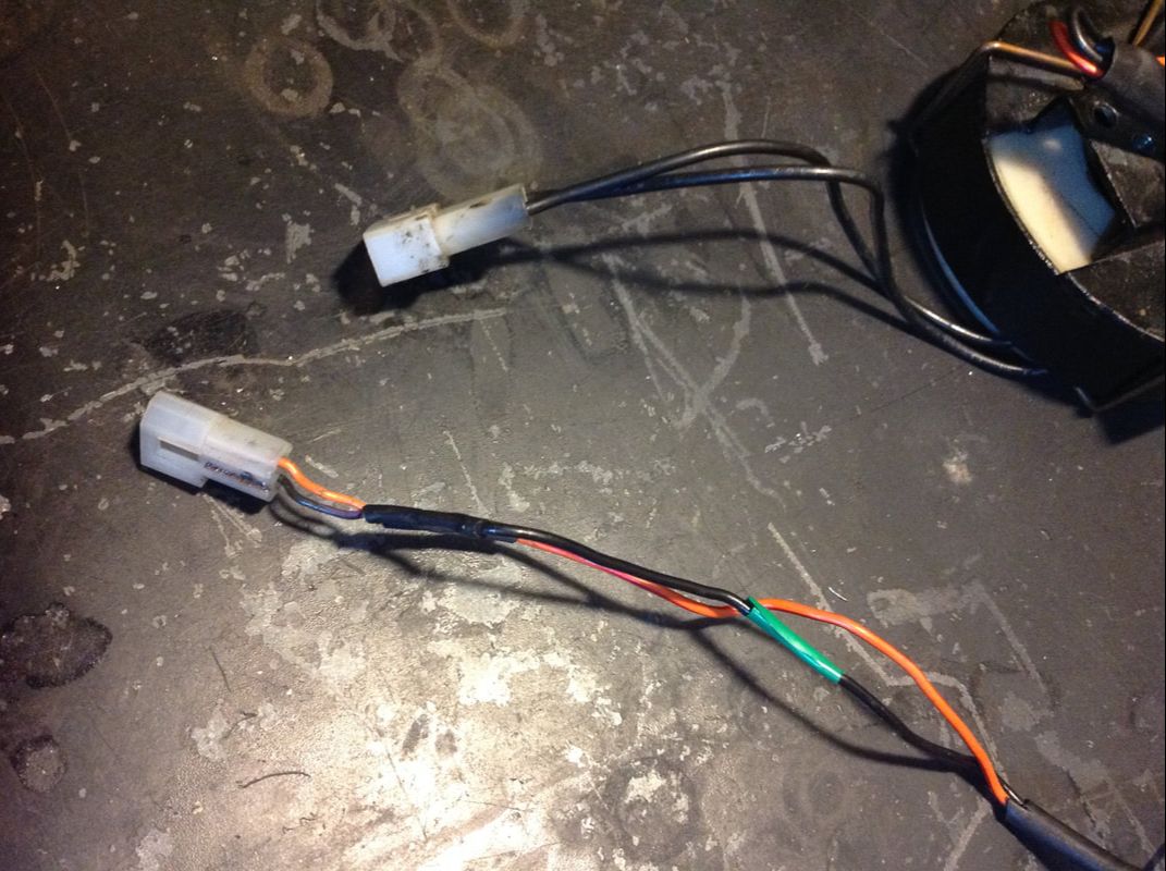
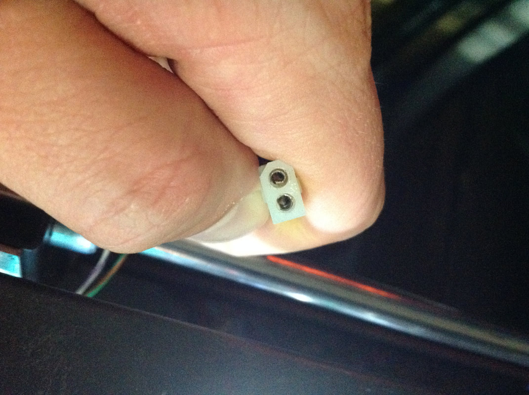
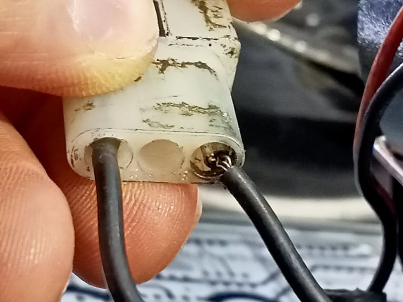
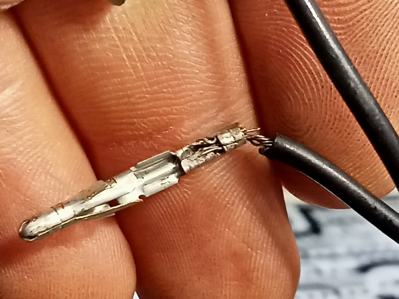
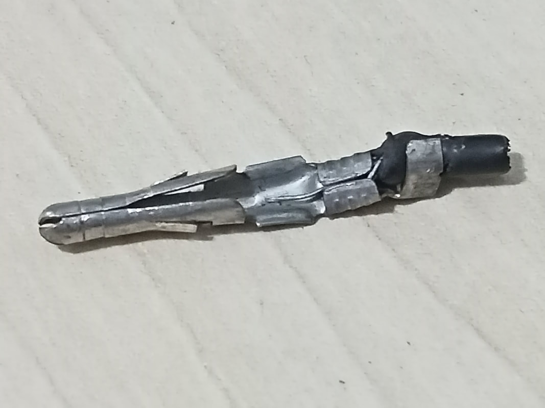
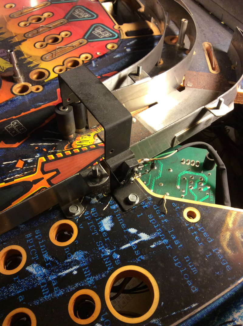
The wiring and connectors for the ball-in-hand switch had seen much better days, with electrical tape and heatshrink all over them. Ugly, yes, but not necessarily a problem. I wasn't in the mood for replacing an entire wiring loom just for the sake of it. I disconnected the hand assembly from the Y rod, held it upside-down, and performed the tests suggested in Williams Service Bulletin 85. I placed a ball in the hand, but the ball-in-hand switch didn't register. Weird. So I double-checked that I had connected the switch connectors together properly. While wiggling the wires around, the ball-in-hand switch started to close and open. Bingo! So, I used alligator clips to jumper the connection between the ball-in-hand switch and the female Molex connector leading to the backbox. I then played a few test games with the jumper wires installed. No ball drops! The Cyberglove moved the ball around with no issues and didn't drop it. So that meant that there was a problem with the ball-in-hand switch connector. The solder joins between the wires and the ball-in-hand switch tabs looked good. There were a couple of previous repairs to the switch wires covered by heat shrink and electrical tape, but there was good continuity through the wire. I wiggled the wires and they did not alter the state of the switch. However, wiggling the switch connector did. Turns out, there was a flaky connection in the connector housing. The suspect connector was the female one. The receptacles had loosened up over time and were no longer making good contact. This meant that movement of the Cyberglove during the game would momentarily disrupt the connection. Retensioning the female connector terminals with a small pair of pliers did the trick, and switch behaviour returned to normal. However! Soon after getting this connector issue fixed, the glove started dropping the ball intermittently again. Unfortunately, the source of the issue was elsewhere. It was particularly important to note that the ball only dropped at random intervals, and always while the glove was in motion. This was still consistent with a wiring or connector issue, which was breaking the connection when the glove was in motion. There are only three devices that move on the Cyberglove assembly: the magnet, the ball-in-hand switch, and the "Y home" position switch. I inspected the wiring for each, and gave a tug on the wires at the connectors. This revealed where the actually source of the problem was: the magnet connector. The crimp pin actually pulled out of the crimp terminal when I gave it a slight tug. I removed both terminal pins with a thin hollow tube. This showed the full extent of the problem. Both crimp terminals were in very poor shape, with only a few strands of conductors hanging on! No wonder they were breaking the connection with a bit of movement. I replaced the 0.093" terminal pins with new male pins (RTBB), crimped them properly, and reinserted them into a new housing (RTBB). Once it was all back together, the ball drops stopped. The moral of this story is that the connectors behind the Cyberglove assembly are all in terrible condition. No doubt, years of being crushed and pulled by the movement of the glove have taken their toll. I have since replaced all of the male and female housings, as well as the crimp pins on the magnet and ball-in-hand switch connectors. I've had no issues since, and suggest this is a good preventative maintenance action even if your Cyberglove is working normally (for now!). Missing spinner
The key to scoring well on Johnny Mnemonic is the spinner. The trick is to earn throwing spike awards in order to light spinner millions (throwing spike award three). This lights the spinner, which will then award ten million per spinner switch hit for the rest of the ball. This score gets added as "spinner millions bonus", which can be increased with bonus multipliers. Often you will get more points from your bonus score than from normal scoring when following this strategy.
On this machine, the spinner was completely missing (part no. 04-10216.1). The switch was still there, as was the spinner bracket, but the spinner itself was nowhere to be seen. I can guess why - the operator probably got sick of people flogging the spinner for massive points, so they removed it to keep scores lower. I can see where they are coming from; the spinner is horribly balanced when you consider the rest of the game's scoring. But given the ability to reduce ball times and scores via software settings, where is the sense in taking the entire spinner out? Moreover, why remove it when you can just cut the wires for the switch and achieve the same result with less work? The mysteries of what goes through an operator's mind! I actually grabbed a new spinner from overseas (Marco Spec). I've since found out that you can grab one locally, too (Mr Pinball). Some forum posts online suggested that the spinner from Junk Yard (part no. 04-10583.1) can be used as a replacement, but they are different part numbers and the arms of the spinners have a slightly different shape. You may be able to use the Junk Yard spinner, or modify it to work, but I just decided to go for the original part. The spinner did not come with a decal (part no. 31-2510), but these are easy enough to get here (Mr Pinball, PSPA). Just stick one on either side and the spinner is ready for action again. Left ramp entry switch not working
This turned out to be a simple issue of a failed diode on the switch. Soldering in a new diode fixed the issue. If you're soldering the diode on while the switch is still installed on the ramp, be careful not to drop any solder on the ramp itself! Faded cabinet decals
I had some flashbacks to my Fish Tales restorations when looking at the Johnny Mnemonic cabinet. There is a lot of red on the cabinet which tends to fade horribly. Mine were no exception and the red was all but gone, leaving a bright yellow behind. As with the Fish Tales, I opted to leave it be as I don't care too much about decals as long as the artwork is still intact. Reproduction decals are getting a little harder to find now due to licensing issues, however some are still around (Ministry of Pinball, Pinball Pt).
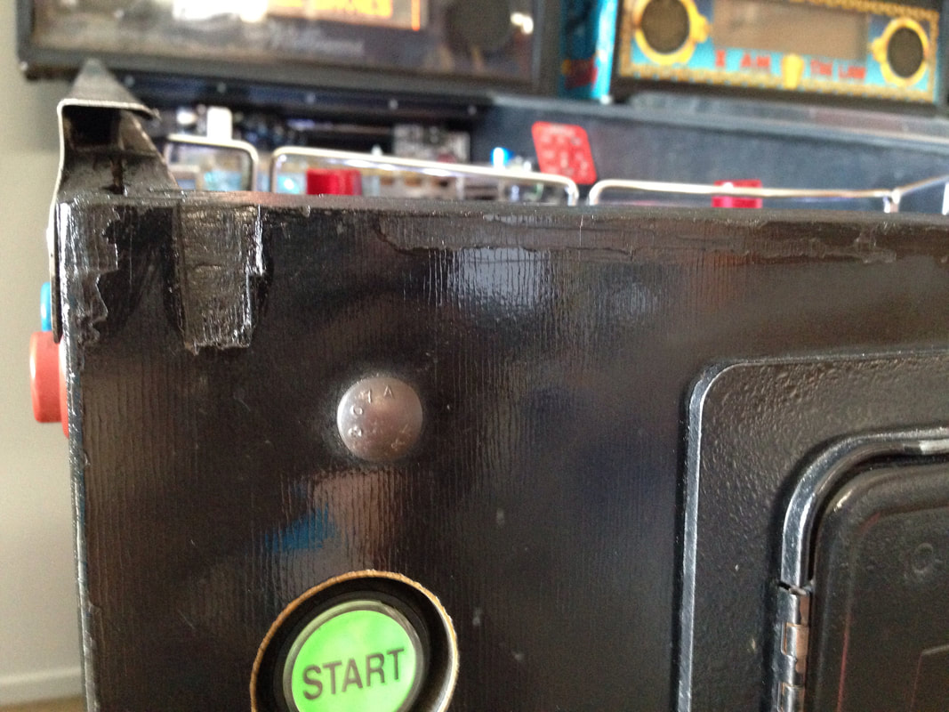
Some edges of the cabinet had some fairly deep gouges in them, especially around the lockdown bar. This part of the cabinet is susceptible to damage as the lockdown bar chews into the wood when it gets inserted into the lockdown bar receiver and eventually chips the wood away. A bit of paint got it looking reasonable again. Ideally, this area should be filled before painting, but as it is behind the lockdown bar, it's hidden from view except when the lockdown bar is removed. Legs in poor condition
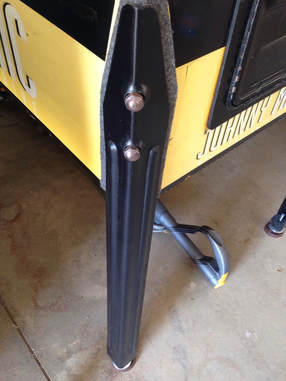
When I first bought this machine, it was fitted with a set of 31" legs. These are the wrong type, so I replaced them with the correct 28 1/2" legs. However, the replacement legs I had were in rough condition. They had been painted black, and some of the paint was flaking off and looking shabby. A respray of all four legs with black spray paint brought them back to life again. I opted for black paint as it seems to fit the colour scheme of Johnny a little better than redoing the legs in chrome.
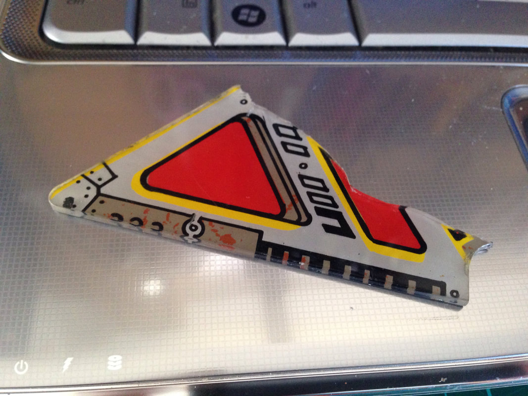
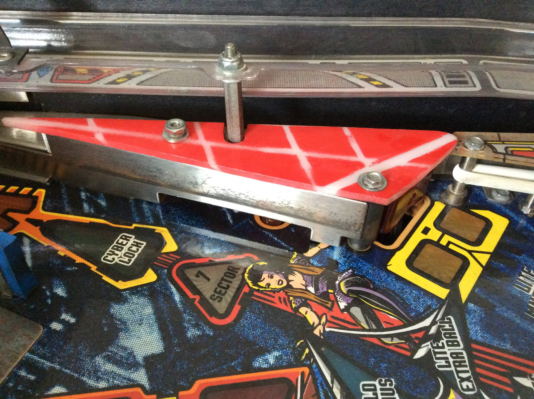
Unoriginal Sector 7 plastic
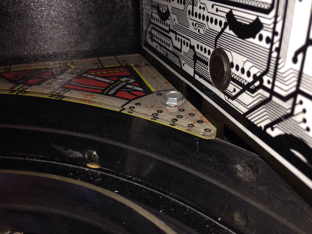
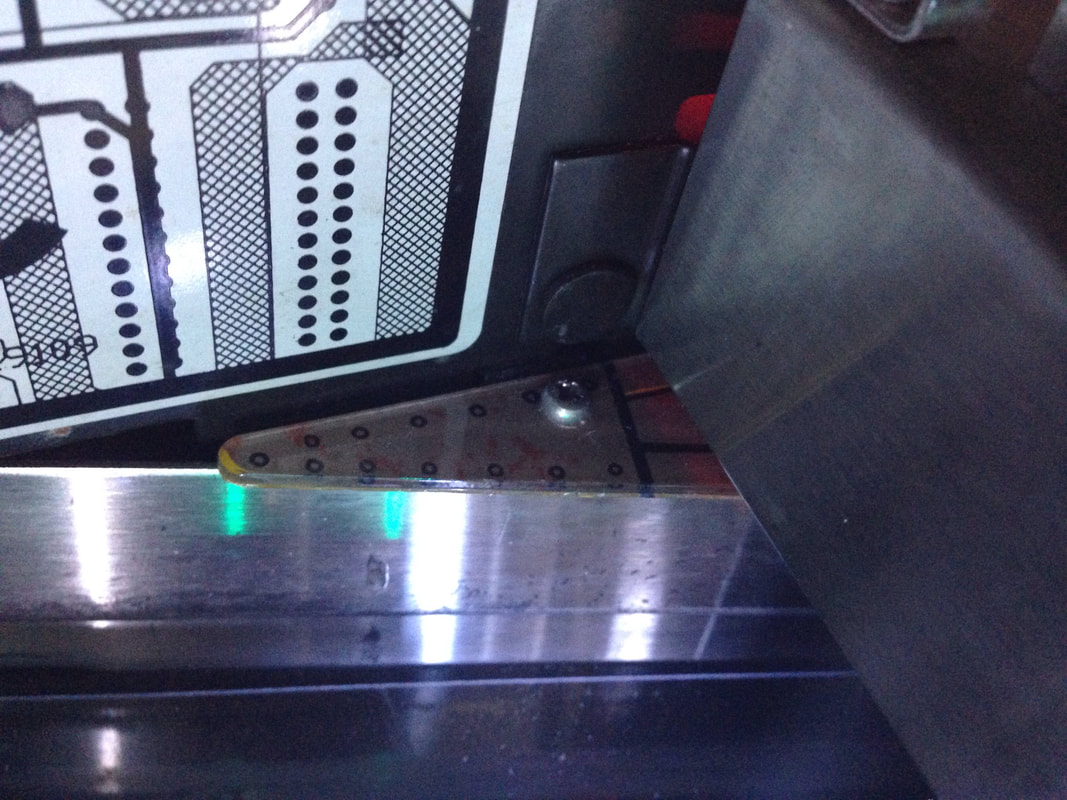
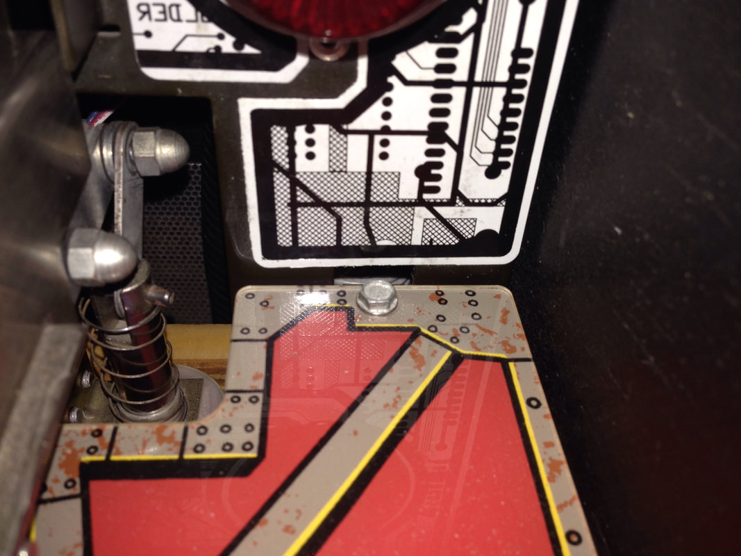
The playfield plastic that sits below the right ramp adjacent to the Sector 7 insert and behind the Mnemonic Recovery standup target is commonly broken. Balls shot from the left flipper to the Mnemonic Recovery target sometimes bounce up off the target and break the plastic. At some point in the past, the previous owner had replaced this plastic with one he made himself. When I first got the machine and had a look inside the cabinet, I found what was left of the original piece. I'm actually pretty impressed with the replacement - it fits nicely and doesn't look too out of place with the colour scheme of the game. Replacements do seem to be available, but only from Ministry of Pinball. But I think the replacement looks pretty good, so I'll leave it be!
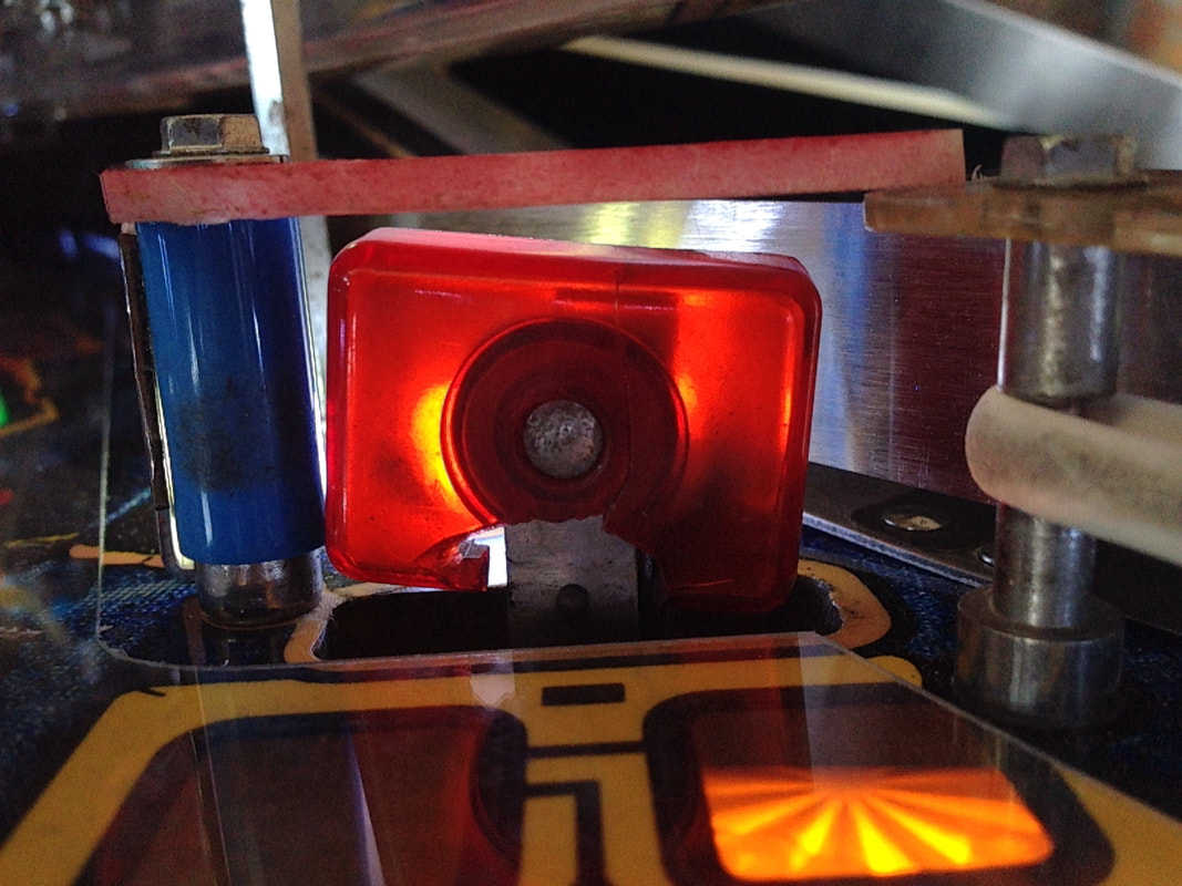
Mnemonic Recovery standup target face broken
The target face on this target was smashed from hard ball impacts. I guess this damage goes hand-in-hand with the broken Sector 7 plastic above the target. The switch still worked but the target looked ugly. I looked around for a replacement but they are surprisingly difficult to get. Standup targets like this (part no. A-20499-9) aren't actually too hard to get, but finding one with a translucent red face is the difficult part. I like to keep my games as original as possible, so I'll keep hunting for one of these targets instead of using a different style. Even Pinball Resource lists them as unavailable. The hunt continues! The target still works and activates the switch reliably, so that's the main thing.
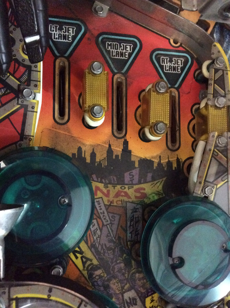
Incorrect pop bumper lane guides installed
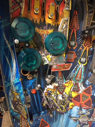
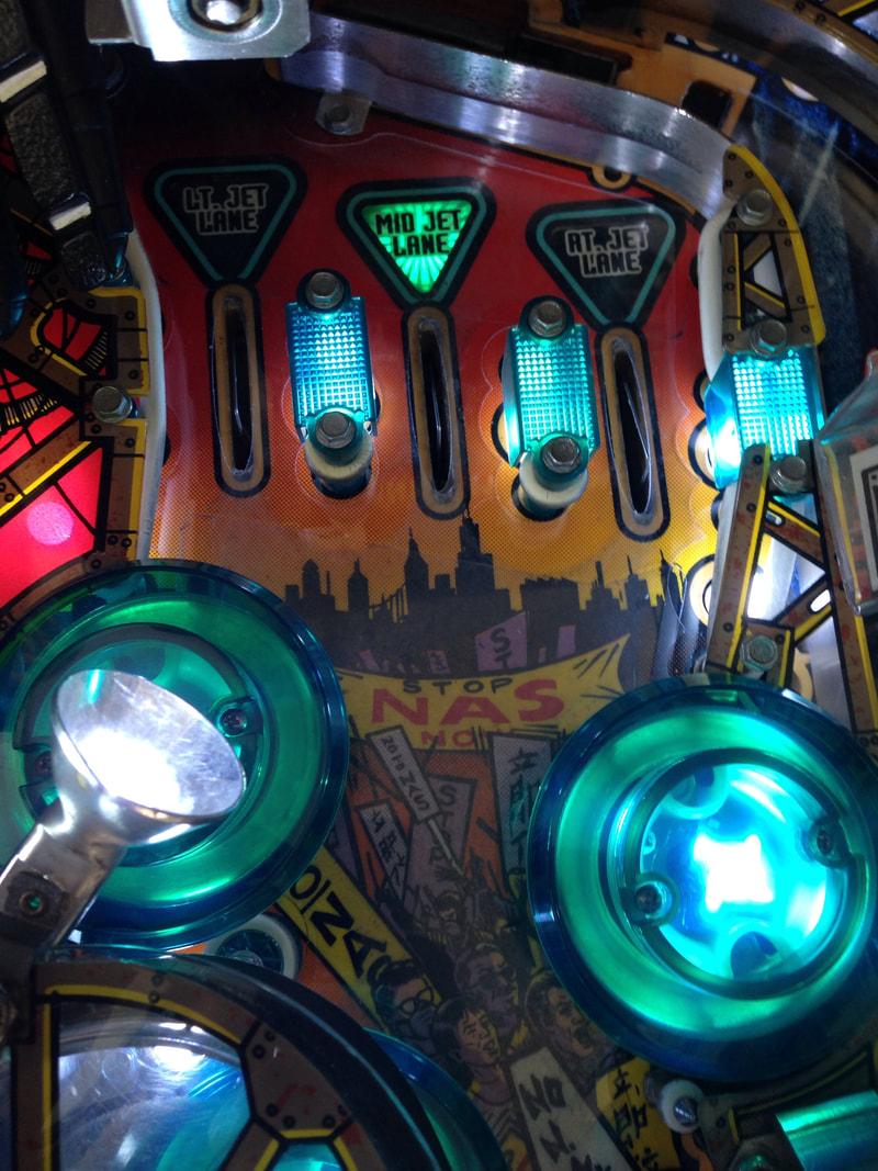
When I first tore down this machine, I didn't even realise that the lane guides were the wrong colour. Mine were yellow, which actually seemed to fit the colours on the playfield better as this part of the playfield was orange and yellow in colour. When I looked in the manual I found that these lane guides are meant to be teal. This matches the pop bumper caps, so also fits in with the theme, I guess. Easy fix!
There's another interesting colour scheme issue to note in this part of the playfield. Originally, Johnny Mnemonic reportedly shipped with teal-coloured bulb condoms for some of the general illumination lamps underneath the left ramp. For whatever reason, these have a habit of disappearing, and are next to impossible to purchase anywhere. If you find any, let me know! Left inlane switch inconsistently registering
As I've mentioned before, one of the big strategies on Johnny Mnemonic is to light spinner millions and repeatedly hit the spinner. To do this, you need to advance the throwing spikes award. You advance throwing spikes by hitting the right ramp or right orbit shot after the ball passes the left inlane. The easiest way to do this is to hit the left ramp and then go straight for the right ramp or orbit shot. However, even when I executed all of the shots perfectly, I wasn't consistently getting a throwing spike award. I tested all of the relevant switches and they were all seemed OK. So something else was going on. I tested everything in switch edge test by pushing the ball around the playfield manually. What I noticed was that when the ball rolled down the left inlane after being placed above it, everything would work normally and throwing spikes would advance. However, when the ball came down the left ramp and was dropped into the inlane, the left inlane switch did not always register. This was another scenario where some slow motion footage helped diagnose the issue.
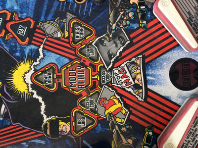
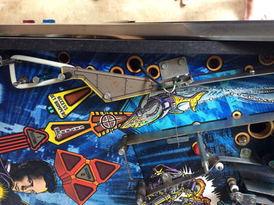
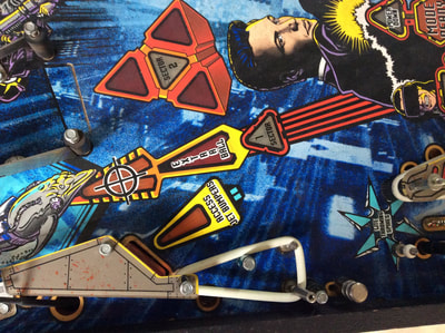
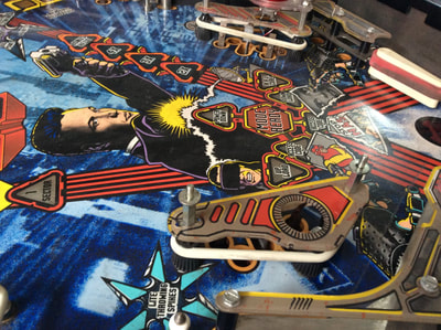
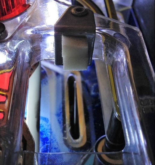
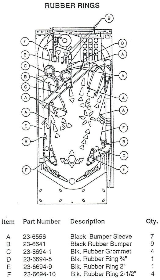
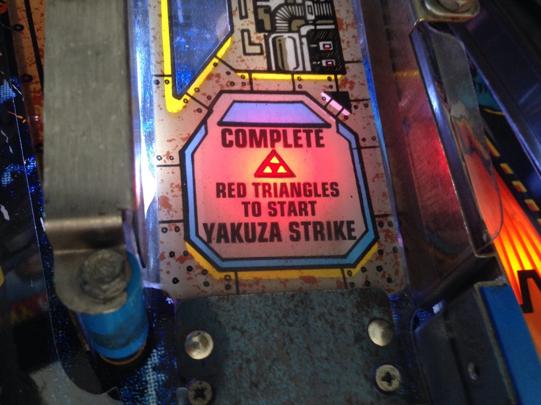
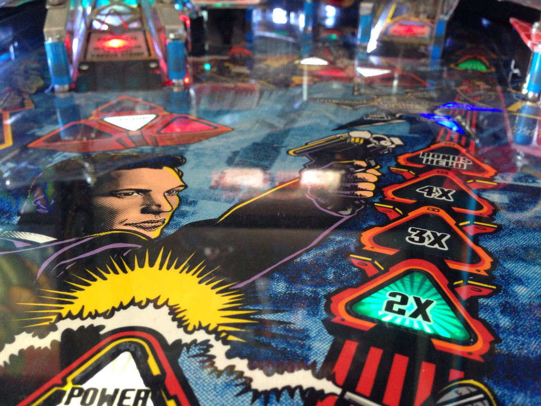
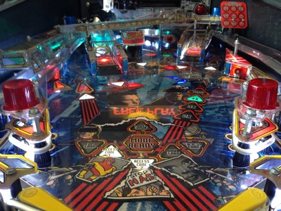
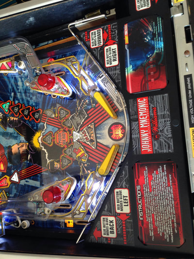
The ball was actually bouncing over the switch entirely when it was dropped from the left ramp. The ball would come to an abrupt halt when it hit the edge of the ramp, bounced around the ramp exit hole a bit, then bounced around after coming in contact with the playfield. Sometimes it would roll over the switch, but often it wouldn't. I tried adjusting the switch actuator (bending it upwards) but some ball bounces still went cleanly over it. The solution was to dampen the ball's movement as it dropped out of the ramp. I did this by placing some weatherstrip foam on the edge of the ramp where the ball impacts before dropping down. This worked well, stopped the ball bouncing around so much, and allowed it to roll more consistently across the switch. Reassembly The most important thing to do when reassembling Johnny Mnemonic is to make sure all components of the Cyberglove and related assemblies are working before they are reinstalled. There's nothing worse than putting all of that work into rebuilding the assembly and realising that you need to take it apart again when it's already back in the game. Work methodically through it (as described in the Cyberglove rebuild section, above), and you should know everything is in good order before it goes back in the game. Other than that, Johnny has quite a simple playfield, so simply reassemble in the reverse order of disassembly. One thing that seems to catch a lot of people out is that there is no rubber ring list in the game manual. An updated rubber ring map was actually released but never made it into the print version of the manual. Instead, it was released in the 1996 Williams Red Service Bulletin Book. I used light blue Cliffy post sleeves for the posts in Johnny Mnemonic as this goes well with the colours on the playfield, especially the bluish background colours. Originally, this game was fitted with white flipper bats and red rubbers. The flyer pictures the game with black flipper bats, but I didn't like the look of darker flippers. So I decided to do something different and went with yellow flipper bats and transparent Super-Bands. Red flipper rubbers would look good also, as was originally intended, but I wanted to try some transparent ones on at least one of my machines. After a couple of hundred plays, my verdict is that the transparent flipper rubbers don't look quite as good as red ones would on Johnny, so I'll be replacing them soon. They also seem to wear more quickly than coloured bands. Not sure why, but it's another good reason not to use them! I replaced all of the rubber rings on the playfield with new white rings. I installed LEDs from Luke's Pinballs throughout the whole machine. Johnny has an interesting lamp colour scheme going on. The lamps under the inlane ball guides had red bulb sleeves, so I replaced these with red LEDs. There was also a red-sleeved lamp under the right ramp, which points upwards towards the red triangle decal on the ramp. With the lamp lit, this creates a cool effect where the triangle glows red. I replaced this with a red LED to reproduce that effect. If you use a white LED or incandescent lamp, the decal glows orange instead of red - not quite the desired effect. The same thing happens on the left ramp, but the problem here is that the lamp is mounted much further back on the playfield, so it doesn't quite light up the decal on the ramp. I fixed this by using a red LED with a flexible lead to reach under the ramp. The ramp decals are now well lit so the triangles are coloured red like they are supposed to be. The only other type of bulb sleeve I found on Johnny was a teal one (teal, not green!) under the left ramp, near the pop bumpers. Some research suggests that a few of the lamps in this area should have had teal bulb sleeves on them, but I only found one. They also seem to be impossible to buy. Green are easy enough to obtain, but teal ones are non-existent. So for now, this area is just lit with cool white frosted LEDs, like the rest of the playfield's general illumination. Frosted LEDs also went into the backbox lamp board. The rest of the controlled insert lamps were colour-matched with flat-top 5050 SMD LEDs. I have noticed that a lot of people seem to get the placement of the flasher domes incorrect. The flyer shows red domes over the slingshots, and blue domes over the ramps, with another red dome on the back panel. Photos of various machines online show some whacky combinations like blue on the slingshots. One person's machine even had yellow domes on it for some reason. I think the flasher effects are definitely best when the domes are set up as they are in the flyer. Or maybe that's just my OCD... Below is a spreadsheet containing the LEDs I ordered for Johnny. Feel free to download it and use it as you wish.
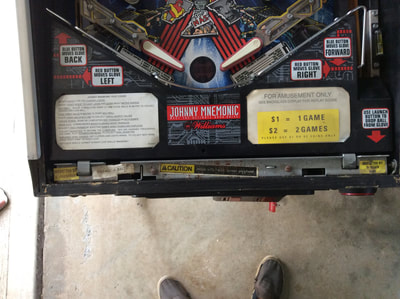
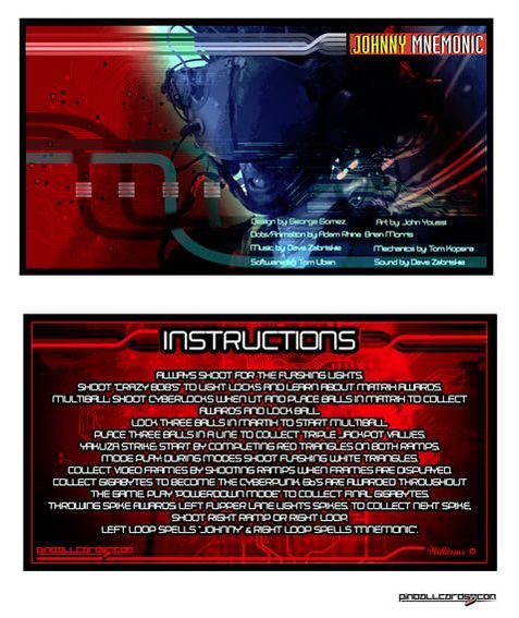
Of course, no restoration is complete without a Makrolon playfield protector overlay from Precision Gas Springs. Unlike most of my other games, which had varying degrees of playfield damage that required touching up, installing the protector on Johnny was more to protect the playfield into the future. Johnny Mnemonic was not a particularly popular game when it was released, which meant that Johnny playfields generally have very little wear. With the protector it will stay in good nick for a long time. Lastly, I grabbed some instruction cards from Pinball Cards. I went for the red version of the cards as it contrasts well with the apron, as well as the red decals on the apron. Conclusion
Even after the restoration, it took me a while to warm up to the gameplay of Johnny Mnemonic. The rules are not easy to pick up and understand compared to a game like Fish Tales (Williams, 1992) or The Getaway (Williams, 1992). The use of the cyberspace matrix to select your jackpot shots is also unique to Johnny. However, once I figured these gameplay elements out, Johnny turned out to be a rocking game. The speed and fury of it, once you get a few consecutive orbit loops going, is unmatched by most machines. You need quick reflexes to play Johnny well. Gameplay can get a little one-dimensional if you're constantly trying to abuse spinner millions for points, but Powerdown is a fun wizard mode and is tough to complete. So there's lots of ways to play and keep me occupied. I likey! While it was a big job to refurbish the Cyberglove assembly, and I have no doubts it will give me the odd issue now and again, it is working well. It really is a shame when it is not working on location because locking balls in the matrix is a cool gameplay mechanic. It's heaps of fun to steal other players' balls from the matrix, too! From a restoration standpoint, Johnny was also a good introduction into the WPC-95 era of machines. I haven't had to do much in the backbox yet, but it has a lot in common with the WPC-89 board set, so I think I'll feel at home. One day I might decide to redo the cabinet decals and give them back their red colour, but for now I'm having too much fun hitting that spinner...
6 Comments
Fredrik Bäckman
8/2/2019 12:01:06 am
Good job, I recently aquired a Johnny Mnemonic as well and intend of doing a restoration of the machine. Did you find a rubber list for the game? The manual seems to be lacking one...
Reply
Hi Fredrik
Reply
peter wagner
9/12/2020 11:10:10 am
I am having difficulty in lowering the top so I can move it to another room. What is that procedure please. I hope you can help me.
Reply
Hi Peter
Reply
Your comment will be posted after it is approved.
Leave a Reply. |
About
Here you will find logs of our pinball and arcade machine restorations, repairs, discussion about general pinball and arcade topics, as well as recounts of our random pinball adventures.
Check back regularly for updates! Blog updates
Archives
May 2024
Categories
All
Donate

Running this website is a hobby for me (just like pinball!). I like being able to show off my restoration work so everyone can learn from it and potentially fix their own machines. If you enjoy reading the site's content or it has been helpful to you, please consider donating to offset some of the website's operating costs. |
||||||||||







 RSS Feed