- Published on
Johnny Mnemonic #2
- Author
-
-
- Name
- Posts
- Posts
-
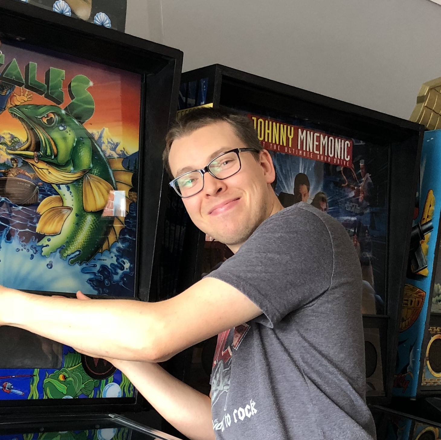
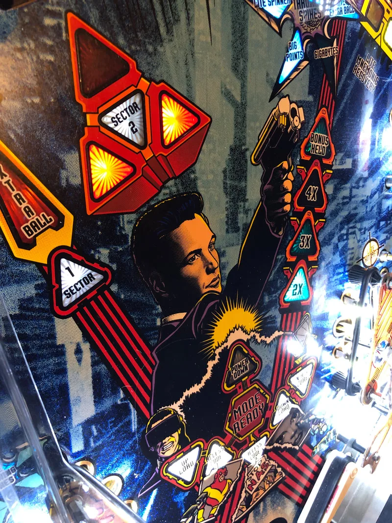
Last year marked the 25th anniversary of the original Johnny Mnemonic movie. This year also saw the release of a high definition version of the original film. This means it's the perfect time for another Johnny Mnemonic (Williams, 1995) blog post! This was quick repair job for a customer who wanted to repair his dad's pinball machine and finally get it into working condition again. His dad used to love playing it and it had sat for too long in need of repair. I was happy to help him out as I love being able to get a machine going again so it can be played and enjoyed like it was intended to be!
This restoration was unusual because the machine was brought to me from several hours away. I had been working on fixing the machine for a couple of weeks when the customer asked if I would be able to have it ready by the end of the week (a couple of days away!) as he was traveling back to his dad's place and wanted to surprise him with the machine. I'm not one to say no to a challenge, so as well as playing lightning fast, this machine was probably one of the fastest repair jobs I have ever had to do! As a result, this post will also be in a shorter format, covering just the things that needed attention.
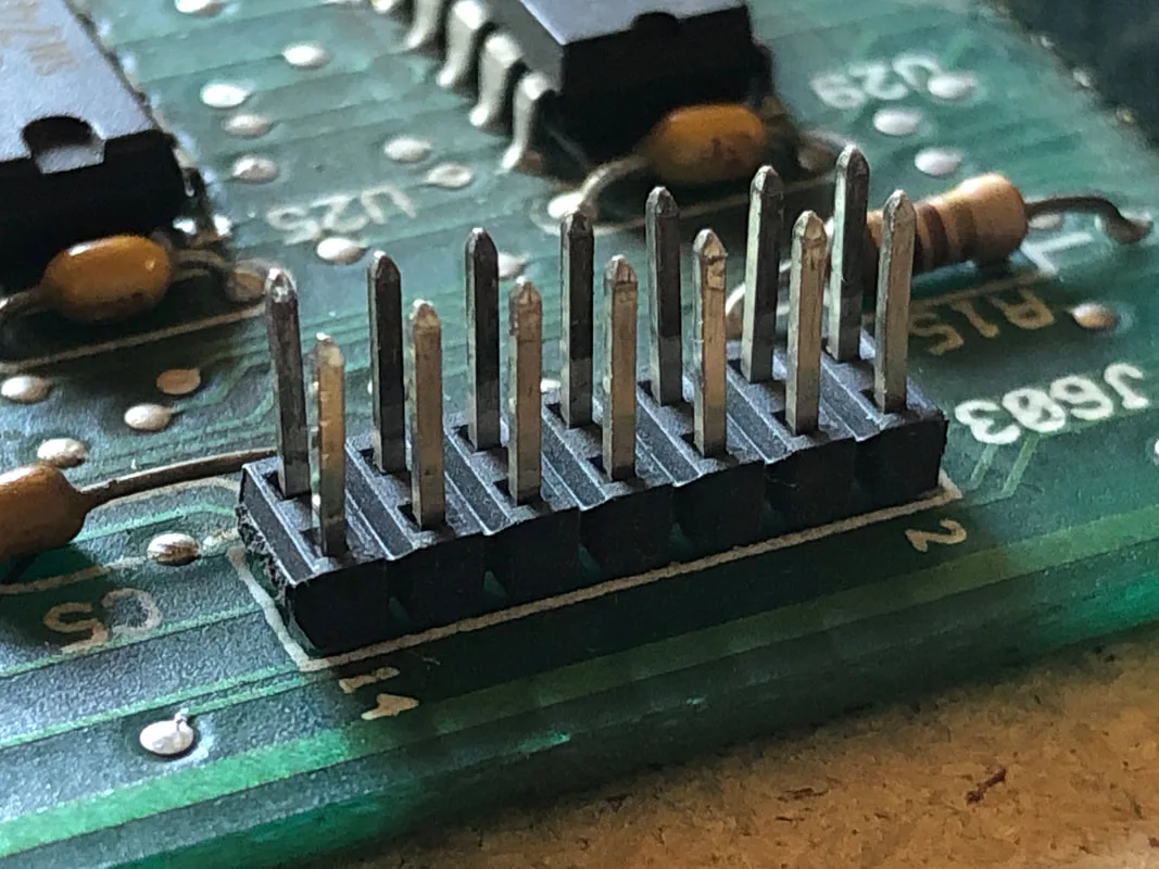
The first, most obvious issue with the game was that the display was not fully working. Only the right half of the display appeared to work as normal, with the left half being totally blank. Testing the game (and being able to read the error messages on the screen) was going to be incredibly difficult unless I could see the entire display properly, so this was the first thing to fix. The first thing I had to address was a damaged connector on the dot matrix display board. The header pins for the ribbon cable connection were severely bent, likely from somebody jamming the connector in incorrectly. When I tried to reconnect the ribbon cable, one of the pins broke off the board completely. This was fixed by removing a spare 0.100" pin from an unused terminal strip, and then desoldering the remains of the broken pin from the board. The new pin could then be inserted into the slot left by the original pin, and soldered in place. I find that there is often no need to remove the entire set of header pins for this type of repair as the single damaged pin can usually be replaced on its own.
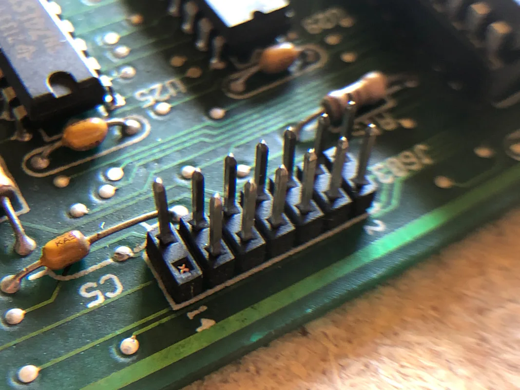
Original header with one broken pin.
Repaired header with new pin installed.

Unfortunately, the broken pin was not the cause of the issue. To diagnose the issue further, I plugged in a known working display. Once the other display was connected, it worked without issue. Bingo! The issue was isolated to the display panel itself.
Testing a known working display in the game - no issues.

Plugging in another display was enough to get the display working for the purpose of further game diagnosis, but I was curious as to why exactly half of the display was blank. This reeked of a logic issue on the back of the display panel rather than an issue with the display glass itself. Potentially, the display could be fixed once the suspect component was found. I might get around to this someday! But for now, a replacement display was all that was needed.
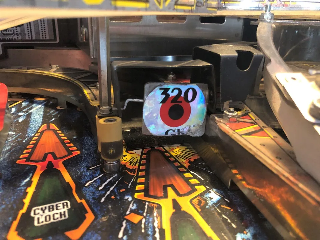
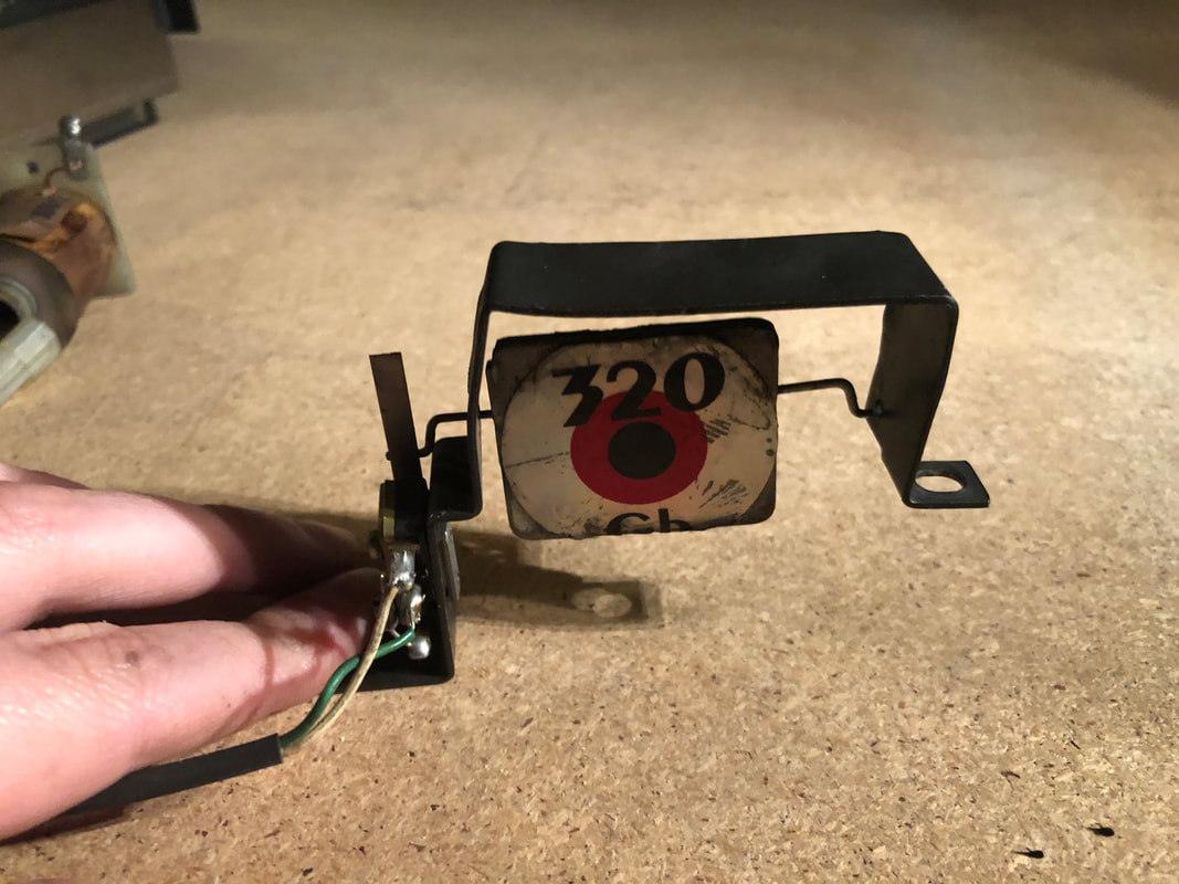
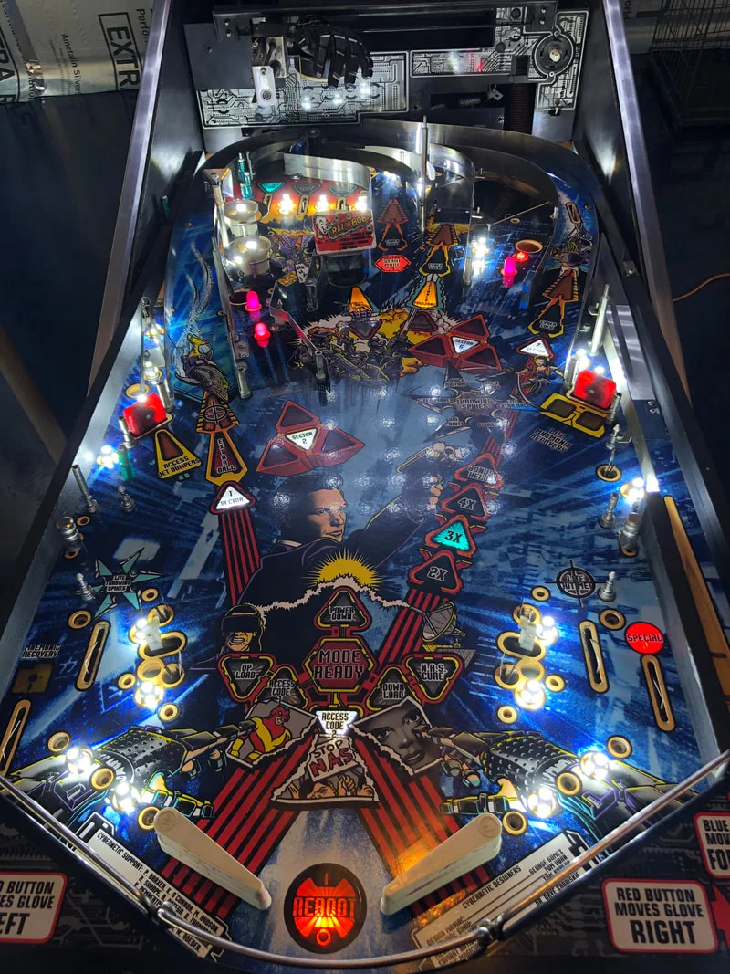
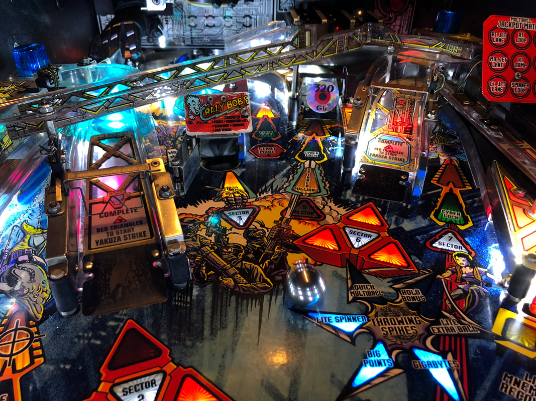
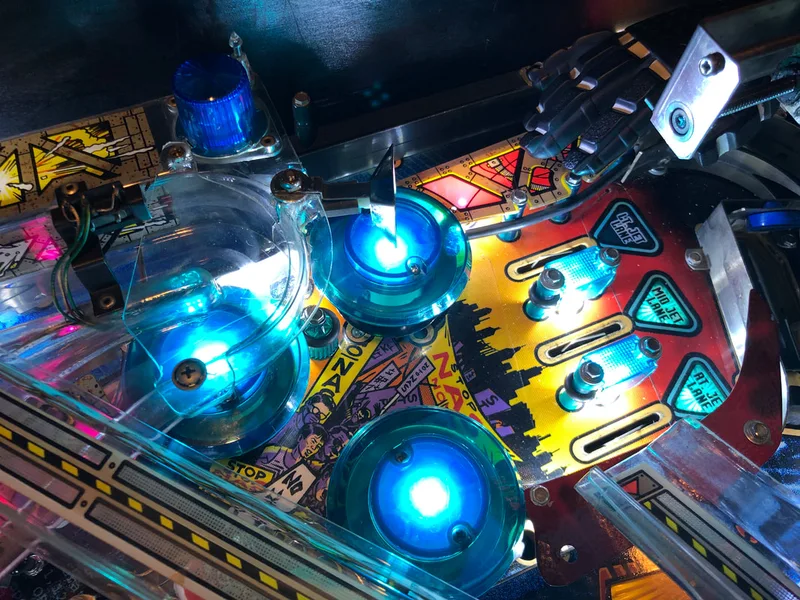
Incorrect spinner type which was also bent and busted!

The only solution here was to rip the spinner out and replace it completely. You can get equivalent spinners locally (Mr Pinball) as well as the relevant decals (Mr Pinball, PSPA).
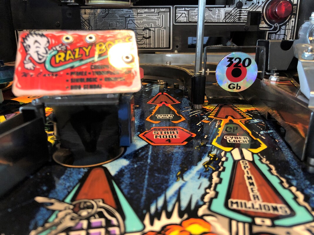
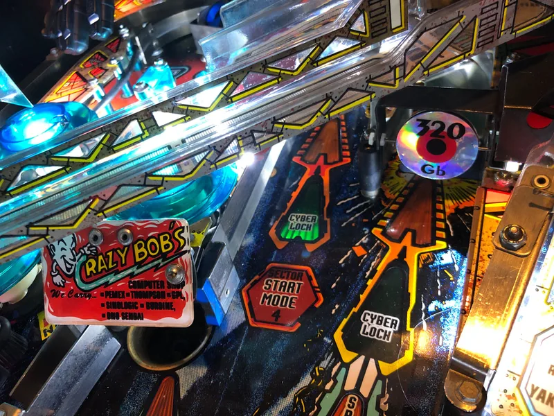
One funny thing you might notice about these replacement decals is that they differ from those originally on the machine in one major way. These replacement decals have two identical sides. The original decals had "320 Gb" written only on one side, while the other side had no text at all. This would give the illusion of the text "shimmering" as the spinner rotated. It's not like the slight change in effect makes a big deal, but for those of you who are sticklers for originality, original decal sets are also available (Marco).
Thankfully, the bracket which holds the spinner was present on this game. Replacements are available if necessary (PSPA). Although this bracket was present, it did need some work. It was bent way out of shape (possibly to accommodate the incorrect style of spinner) and needed some good straightening out with the vice and mallet to get it square again.
View showing how bent out of shape the spinner bracket was.
When reassembling any spinner, take note that you will need an additional part to make sure the spinner works well. Most spinners use small nylon washers on their spokes in order to hold the spinner in position and prevent it from sliding side to side in its mounting brackets. The size of the washers depends on the spinner assembly. These parts are not usually listed nicely in the game manual so you may have to go digging through the parts list. Using the parts list and searching for the spinner assembly (part no. A-20448), you'll find a part labelled "washer-.07". This is the washer you'll need (part no. 03-7796, RTBB, PSPA). The parts list specifies only one washer however I think you need two washers to securely hold the spinner in place (flanking one side of the spinner bracket). Once all of the new parts were ordered and the spinner bracket was straightened, it was a pretty simple affair to put them all back in.

The newly installed spinner, spinner bracket, nylon washers, and spinner decals.
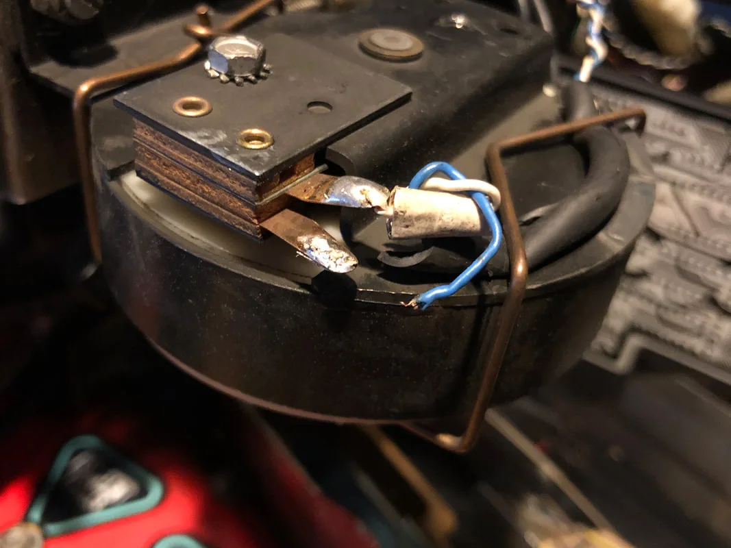
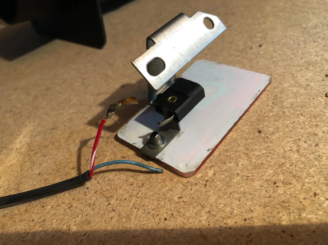
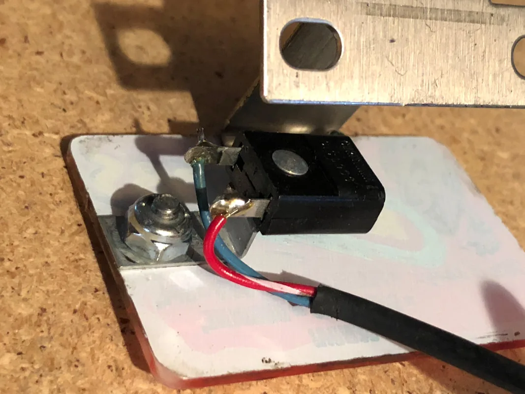
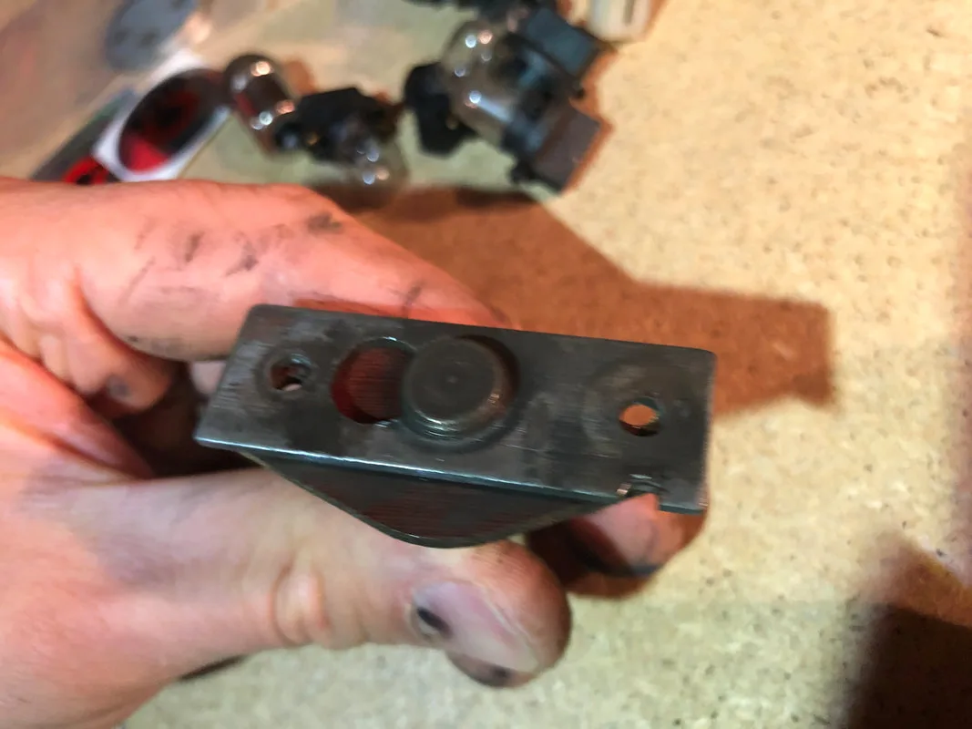
Broken wire on Cyberglove ball in hand switch.
A quick check of the flasher showed that one of the wires which connect to the socket had come loose. However, once it was soldered back on, the flasher still did not work. All of the other flashers and coils worked in test mode, none of the fuses were blown, and there was even the expected voltage at the lamp socket lugs (20 volts). So why wouldn't this flasher light up? I unbolted the plastic assembly from the playfield and took a closer look at the flasher socket. Upon closer inspection I could see that the terminals at the base of the flasher socket had large gaps in between them. I reinstalled a flasher lamp, and wiggled it around a little. Some of the time, the lamp would flash without issue, but a few seconds later, after it was moved, it stopped working again. This confirmed that the problem was the flasher socket itself. The terminals were worn and no longer making good contact with the flasher tabs. So, it was time to replace the socket.
The problem with this socket was that it was riveted to the Crazy Bob's plastic. This was a fiddly rivet to remove as it seemed to be quite tight in the mounting hole. I shaved away at the rear of the rivet (carefully) with an angle grinder until it was almost flush with the rear of the plastic. Do this carefully so as not to melt or crack the plastic. Then, with a small punch, I was able to knock the rivet out of place. The new socket could now be installed (RTBB, PSPA).
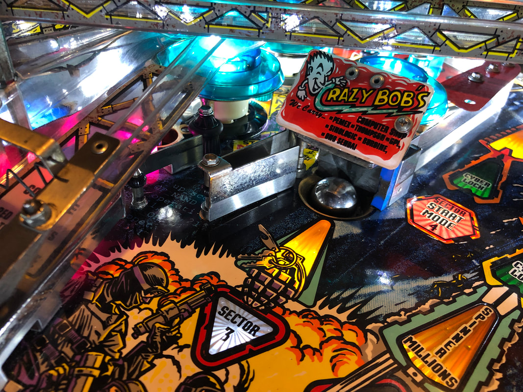
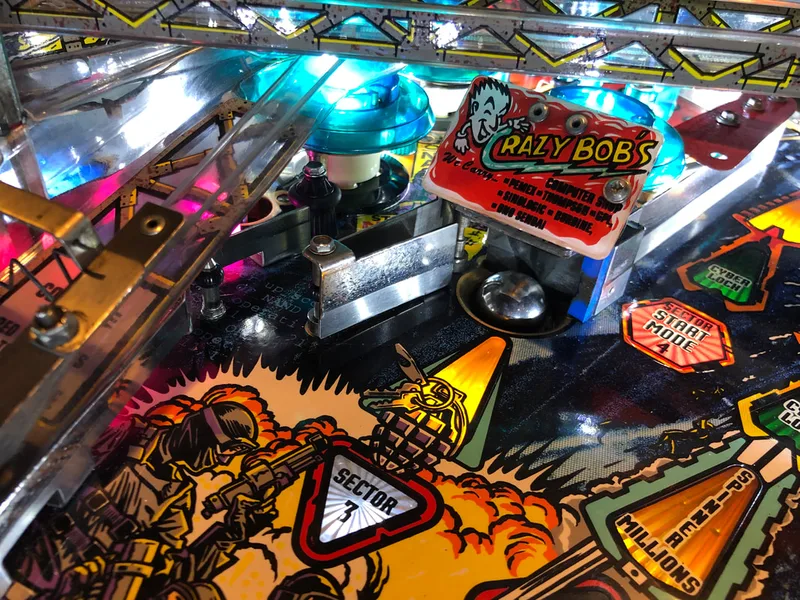
Original Crazy Bob's flasher with broken socket and disconnected wire.

New socket installed and wires attached.

A lot of purists like to replace rivets with more rivets. I think this is stupid. Rivets only really serve a purpose where they are used in ball travel areas where a bolt or screw standing proud can potentially impact the path of the ball. Ramps are a great example of where rivets serve a good purpose: they need to be flush with the ramp or other surface so the ball doesn't strike them. But we are talking about a playfield plastic here. There is no reason this rivet cannot be replaced with a screw as the ball has no business being up here. Rivets are great in manufacturing processes where minimal parts and labour are desired, but we don't have that requirement anymore. So, I replace these rivets with screws and nuts. Shiny new screws look quite nice, and they allow for easy disassembly in future, if required. Keep a stock of #6-32 screws (RTBB, PSPA) and threaded nuts (RTBB, PSPA, Mr Pinball) in stock, as they are perfect for these small holes in plastics where rivets were originally installed.

New Crazy Bob's flasher socket installed (with screw).

Blown fuse at F112.
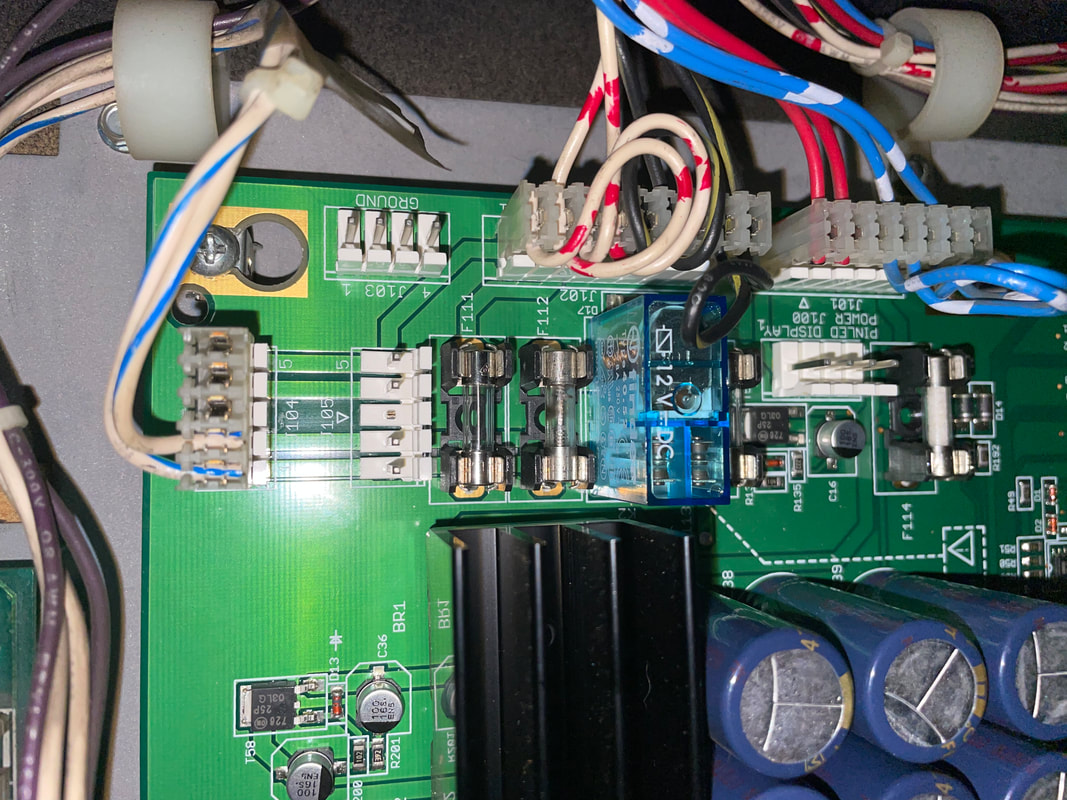
Dealing with blown fuses on this power driver board was a novel experience for me as this was the first time I had worked with a PinLED replacement power driver board. PinLED reproduction boards are made in Germany and they are not particularly common, especially in Australia. While the PinLED board is a direct plug-and-play replacement for the original WPC power driver, there are a couple of idiosyncrasies in its design that need to be taken into account when troubleshooting.
First, the game uses smaller, M205 style glass fuses instead of the larger, 3AG style fuses which can be found on original power driver boards. Don't try and wedge a 3AG style fuse into a M205 size holder - it simply will not fit! Thankfully M205 fuses are readily available (Jaycar). Secondly, many components on the PinLED board are surface-mounted and have been upgraded to different component types. For example, the bipolar transistors that make up a typical solenoid drive on the original board have been replaced with a single, surface-mount MOSFET. While there is no difference to the connector pinouts or the operation of the board,you'll need a completely different set of soldering equipment and components in order to be able to do component-level repairs on this board. There are other minor differences in the design of the PinLED board, but these all appear to be reasonable upgrades which add to the reliability of the board. PinLED produced an excellent technical document which explain the theory of operation of the board and the differences compared to the originals.
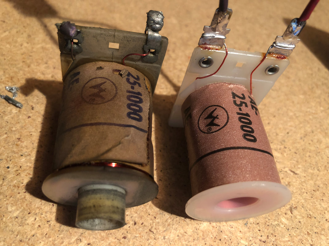
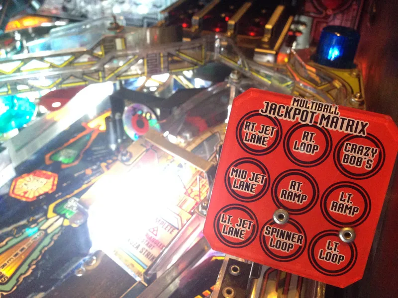
Where were we? Oh yeah, the blown fuse! I replaced the fuse with another and it blew again, so unfortunately the issue wasn't as simple as that. More investigation was required. Fuse F112 was on the solenoid secondary winding circuit, which suggested there may have been a problem with one of the game coils. I propped up the playfield and had a look. Initially I didn't see a problem with any of the game coils, until I put the playfield down again to check on one last coil - the matrix release coil at the very rear of the playfield. This coil engages to push balls out of the Cybermatrix, and is actually "on" the playfield rather than underneath it. The coil appeared to have locked on at some stage and burned up. The coil plunger was wedged inside. This would have been causing F112 to blow due to a short within the coil winding. Changing this coil was a fairly simple affair as the coil can be removed from the assembly via a connector. The connector can then be desoldered and reattached to the lugs of the new coil. The only hard part was wiggling it out and under through the small hole in the playfield! Once the new coil was in and a new fuse was installed, I fired up the game to test. The clear matrix coil turned on immediately and stayed locked on. Whoops! I turned off the game before any damage was done.

Burned original coil on left and new replacement coil on right.
This meant that another component was fried: the transistor which drives this coil. Potentially, this transistor had fried previously and caused the coil to lock on. Replacing the coil fixed the symptom but not the root cause of the issue. So, back into the backbox we go! The PinLED technical document on their power driver is very helpful, and contains troubleshooting steps for testing potentially damaged MOSFETs.

PinLED instructions for MOSFET testing.
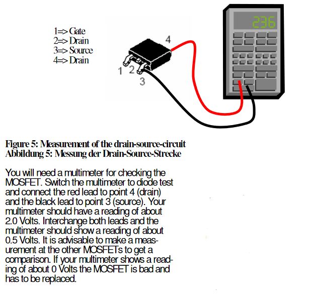
So, testing the suspect MOSFET is all well and good. But how do you figure out which one to test? The FETs are labelled differently to the transistors on the original boards. The clear matrix coil transistor on the original board was Q64, but no such marking appears on the PinLED board. It would have been handy if PinLED used the original component designations, or produced a table of new and old designations, but they do not. However, there is another way to find out which component is equivalent to Q64. As the connector pinouts are the same on the original and PinLED board, we can simply go backwards from the drive wire which leads to the clear matrix coil. In this case, the wire is violet-green, and is connected to J130, pin 6. The MOSFET connected to this pin on the PinLED board is labelled as T29. And bingo! We found our faulty component. This MOSFET had shorted internally across the source and drain pins.
Instead of replacing a number of transistors, I only had to replace one. The faulty MOSFET was listed as a STD25NF10L in the PinLED manual (100v, 25A). The problem was that I did not have one of these MOSFETs spare. I also did not have the capability to properly desolder a surface mount component such as this, nor was I able to solder a new one in, even if I did have one. I had planned to send this board out to a friend to replace this single FET.
However, at this point the owner of the machine contacted me out of the blue and said that he wanted to take the machine back home the next day. I let him know that I needed some more time to repair this issue properly, but he asked me to see if I could repair it before tomorrow. I told him that I could get it done, and it would be fully functional, but the repair would not be pretty. He didn't mind.
At this point I had to think of how I would fix this MOSFET without the necessary replacement parts. The first challenge was removing the faulty FET from the board. Without a hot air rework station, removing surface-mount components can be difficult. However, depending on the component, it is far from impossible. These FETs were mounted to the board via three solder pads: one at the gate pin, one at the source pin, and one at the drain tab. The gate and source pins can simply be clipped with a small pair of side cutters. The drain is connected to both the drain tab at the topside of the FET as well as the central pin. If the FET were attached to the board via the central pin only, removal would be simple as this pin could be clipped in the same way as the source and gate. However, the drain tab (much larger surface area) is soldered to the board instead of the drain pin (much smaller area). It is also attached with a fairly large amount of solder. So, the trick to removing these FETs with a regular iron is to add some solder to your iron and hold it steadily on the drain tab until the solder underneath begins to liquefy. You'll need to hold it here for quite a while. As soon as it liquefies, remove the FET with a pair of tweezers or pliers, making sure that the solder is all molten. If you sense any resistance, do not continue to pull the transistor away from the board as some of the solder may still be attached and solid. Stop pulling and continue to heat the drain tab until the solder melts completely. Using this method I was able to remove the offending transistor at T29.
The next problem was sourcing a replacement MOSFET. Ideally, you would just order correct replacements (RS Components). As the customer wanted to pick up the game tomorrow, I didn't have time to order a replacement part. So, thinking like an operator, I used what I already had! Most games use most, but not all, of the solenoid drive circuits. Looking at the solenoid table in the manual, unused solenoid circuits are indicated by "NOT USED". This means that unused circuits exist on the power driver board, with components that are sitting idle. In a pinch, you can "steal" the unused components to enact a repair, and that is what I decided to do in this case. I chose the Solenoid 8 circuit, connected to J130-9 via the MOSFET at T32. Using the same procedure as above, I removed T32, and connected it to the solder pads at T29. As I could not neatly reattach a surface-mount component without a rework station, I used some jumper wires to attach the FET. This will make it an easy hack to "correct" in future, if necessary.
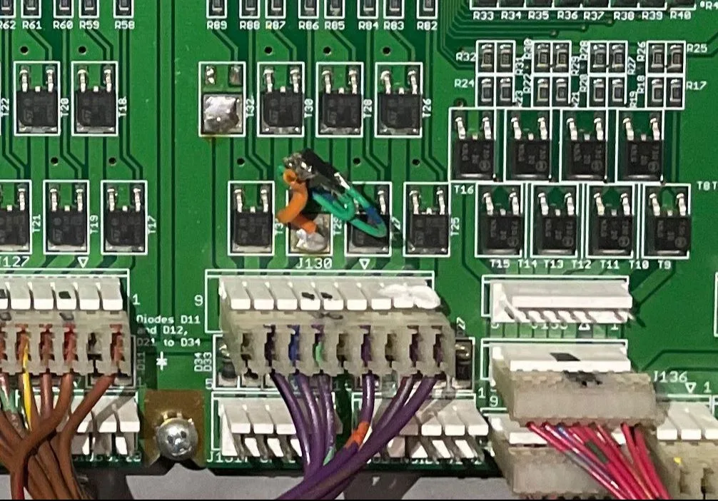
Repair of T29 by stealing T32 from an unused solenoid circuit.

And after this point, the clear matrix solenoid worked perfectly! While this was an ugly and somewhat hacky repair, it got the job done in the timeframe necessary and the customer was happy.

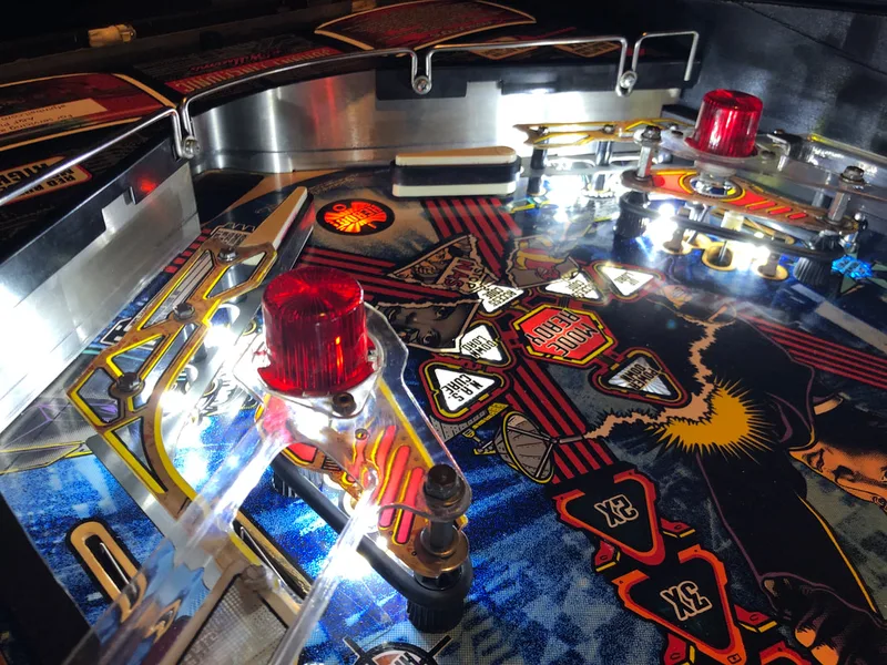
Pop bumpers in their original condition.
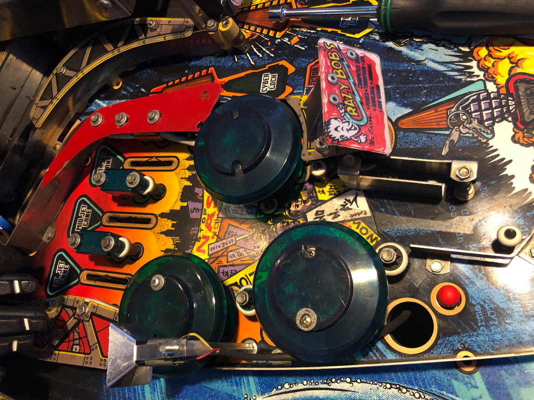
All of the pop bumpers on this game needed a service. All of their wafers were broken, so the entire assemblies needed to be removed from the playfield. During the process of rebuilding the mechanisms, I found that the metal yokes (part no. 01-5492) had been replaced. Their replacements were not original parts, but thicker, rectangular pieces of steel which had been cut to size. Obviously, the original yokes had broken at some point in the past and an ingenious operator or owner had fabricated new ones. Now, usually I am not a fan of hacked-up or fabricated parts which do not match the originals. However, I have to give credit where credit is due here. These replacement yokes were much thicker and therefore stronger than the originals. This is a huge upgrade over the crappy Williams yokes, as they were incredibly weak and broke frequently. So I was happy to simply clean these yokes up and reinstall them as they were. They fit nicely in the pop bumper assembly and worked perfectly. Thumbs up to the ingenious operator who had these yokes made - they are still going strong! After these bumpers were rebuilt, balls shot into the pop bumper area would smack around for what seemed like forever; just how it should be!
Custom fabricated pop bumper yoke.
Of course, the pop bumper rebuilds also included new wafers/skirts, and two new bumper caps to replace ones with broken screw holes. The pop bumpers on Johnny Mnemonic always look great after a rebuild; I love the teal colour and it's a shame it wasn't used on more games. These teal caps are only used on Johnny Mnemonic and World Cup Soccer (Bally, 1994). If possible, use caps with raised tops (part no. 03-9030-25, RTBB, PSPA) as opposed to the lower-top ones used on Cactus Canyon (part no. 03-8254-25).

Pop bumpers after being fully rebuilt.
I looked at the sound board in the backbox, where all of the audio data is stored. Nothing appeared out of the ordinary in terms of sound board components (i.e. no blown capacitors, no damaged connectors, etc.). Next, I looked at the ribbon cable which connects the CPU, to the Fliptronic board, to the sound board, to the display driver board. This 34-pin ribbon cable (part no. 5795-13018-01) is usually the first one people suggest reseating when you start having weird issues with sound or images on the display. Strangely, after reseating the cable, some of the sounds appeared to play properly. However, other events which triggered specific sounds were still not playing the right ones. But the fact that the issue improved once the ribbon cable was reseated suggested that it was the issue after all. A new ribbon cable was ordered (PSPA, Mr Pinball, RTBB) and once installed, all of the sounds played as normal. This confirmed the previous ribbon cable had worn out.
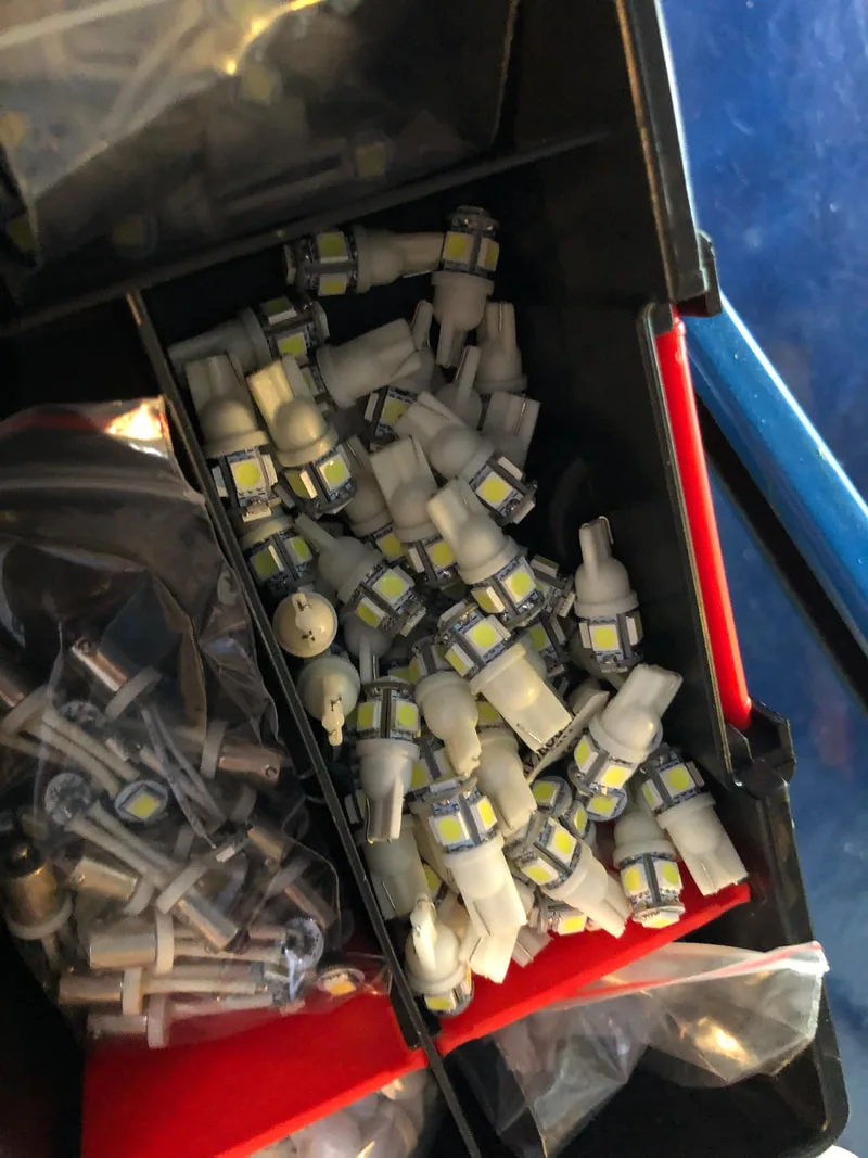
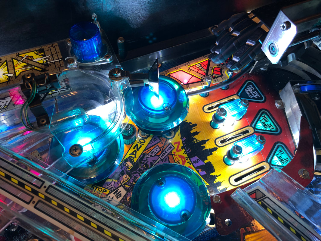
Installation of cool white LEDs.

General illumination installation complete!

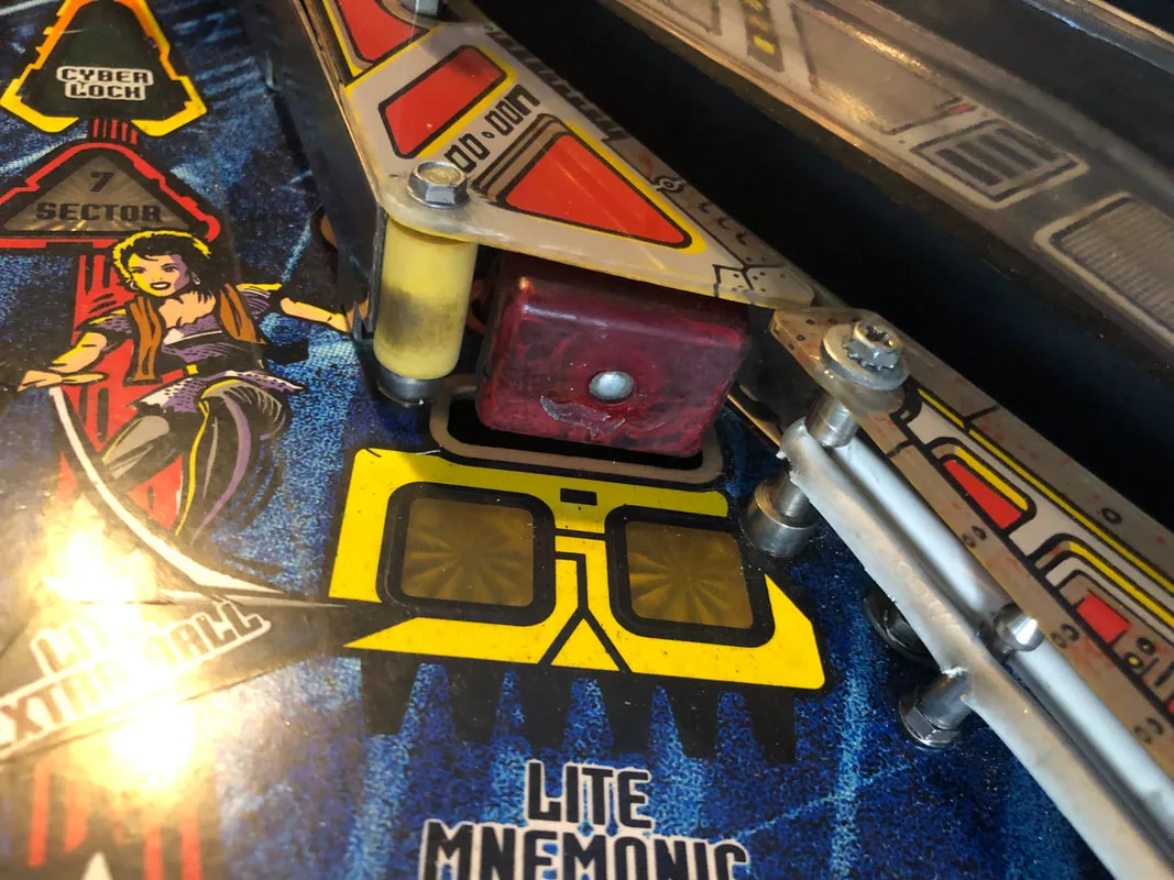
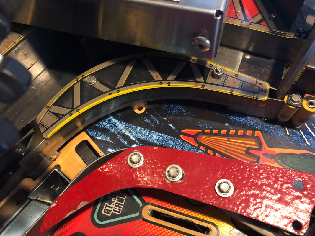
First, a fully intact Sector 7 playfield plastic! Plus, the Mnemonic Recovery standup target underneath this plastic was also completely intact. I was extra jealous of these as the plastic on my game is missing entirely, and the standup target face is broken.
Fully intact playfield plastic!

Fully intact standup target!

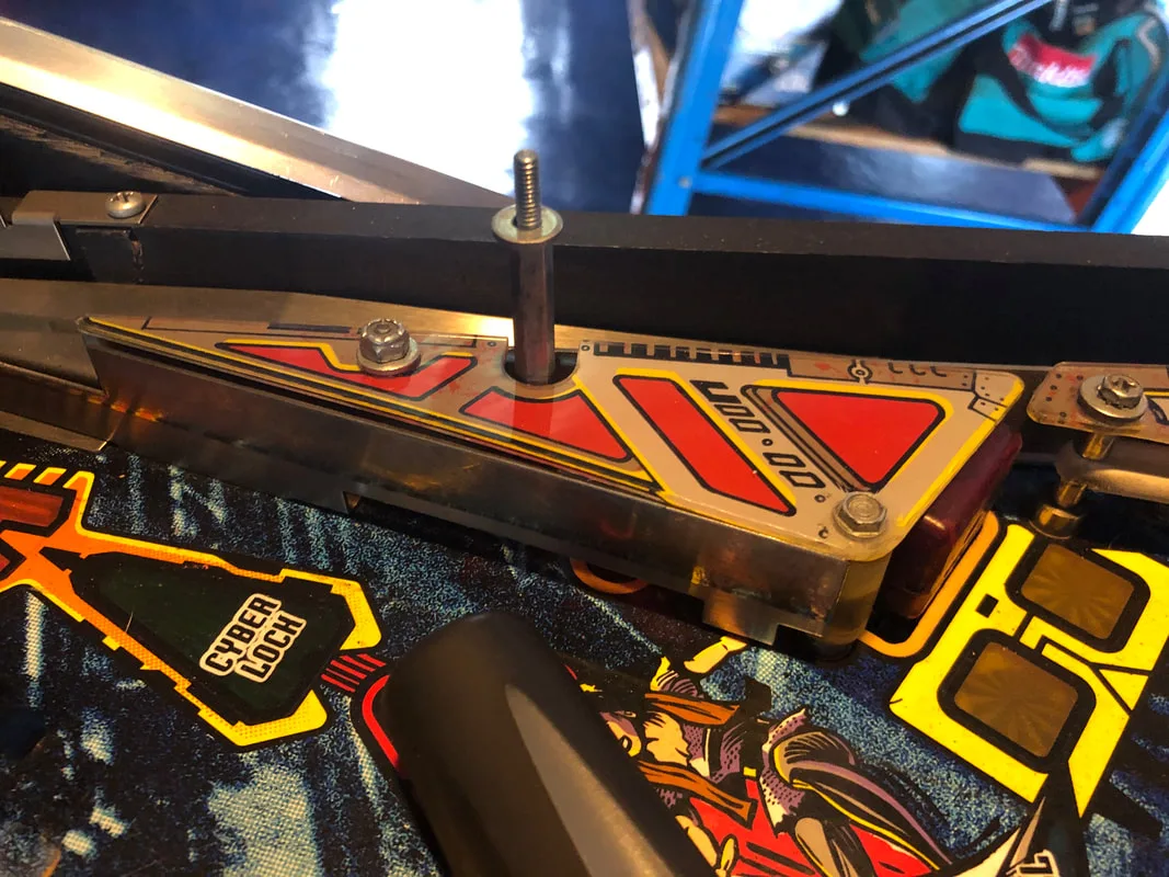
However, there were two playfield plastics which were missing from the game. These were the ones directly above the right pop bumper. They had been replaced with a single piece of red plastic material. For the most part, these pieces are hidden from the player's view by the ramp assembly and the Crazy Bob's plastic. The customer in this case didn't want to bother with replacing these pieces. However, should you find these plastic pieces missing on your own game, replacements are available (Ministry of Pinball).

Makeshift red plastic material replacing original plastics.
The second interesting thing was this ingenious flipper rubber replacement which made me chuckle. I love seeing what kind of repair methods people come up with when they don't have the correct parts! Of course, as ingenious as they are, I replaced these with proper flipper rubbers.

Ingenious flipper rubber replacement.
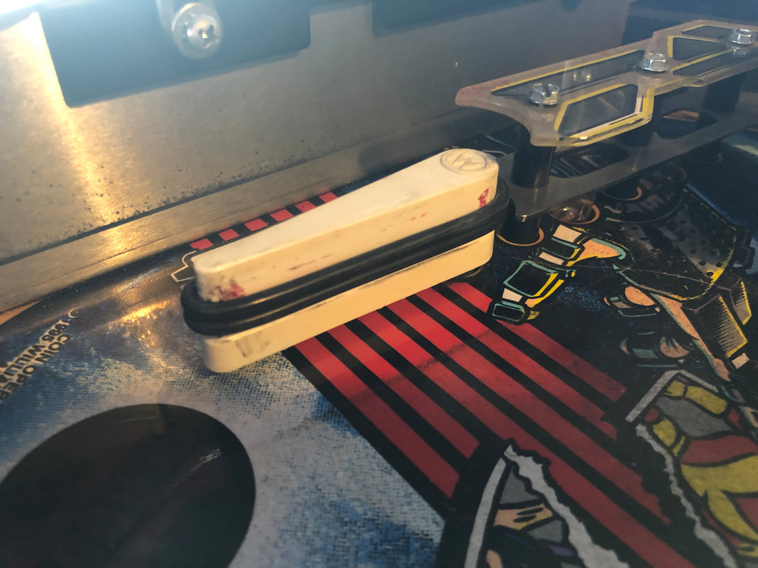

Proper flipper rubbers at last!

Third, a bit of machine history. This was a former Bumper Action Amusements machine. I see a few Bumper machines in the course of my repairs and it's always interesting to see how far they travelled from Bumper's warehouse in Melbourne. There is a lot to the history of Bumper in the Australian pinball scene.
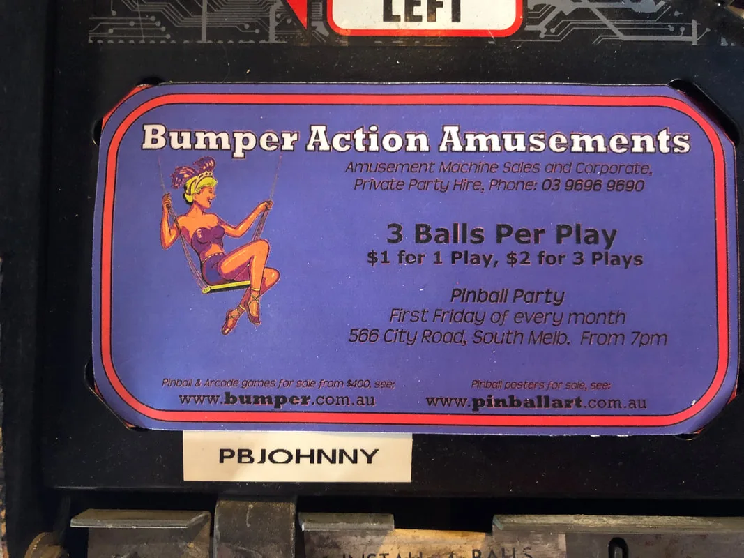
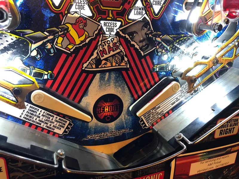
A reminder of simpler times!

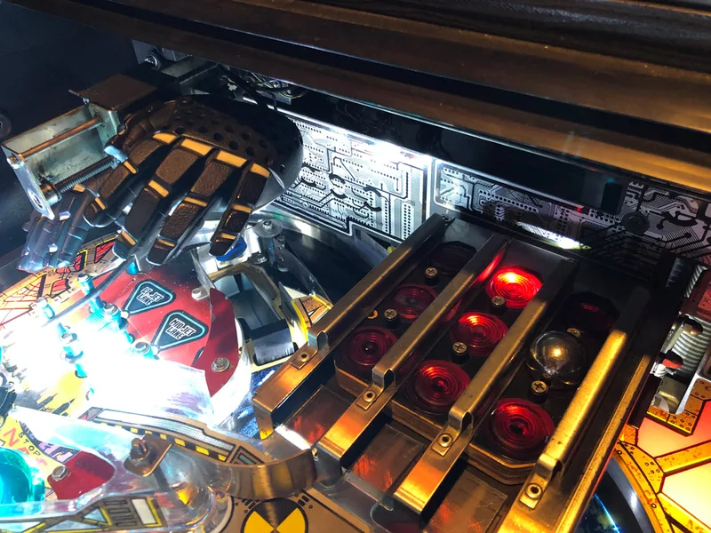
Miraculously, the Cyberglove assembly on this game worked flawlessly. It's the first time I've seen a Johnny Mnemonic with a Cyberglove I didn't have to work on. I'd even go as far as to say that it worked better than my own!
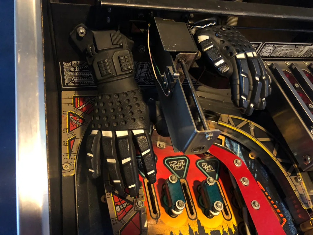
A fully working Cyberglove!

This repair was a quick and clean one, with a number of relatively simple fixes to address in different parts of the game. I like doing these types of repairs instead of simple playfield refurbishments, as diagnosing occasional simple issues helps break the monotony of cleaning so many playfield parts! I learned a few new things working on this game though, particularly regarding the PinLED power driver board and how it works. The incorrect sound effects issue was also an interesting one which I haven't encountered before. As long as you learn something, it's a successful repair in my mind!
Of course, the entire playfield was stripped down, cleaned, and reassembled. New rubber rings were installed across the playfield. Don't forget that there IS a rubber ring map available for Johnny Mnemonic (see my previous blog post) to make this easier! There wasn't anything else on the playfield that needed repair, although a couple of star posts needed replacement. All other mechanisms were working as intended. One leg bracket (part no. 01-11400-1) was also replaced, as the threads within it were destroyed. Always be sure to use upgraded leg brackets as replacements (RTBB, PSPA, Mr Pinball, Austral Amusements) as they have a much deeper thread to engage the leg bolt.
And with that, the machine was finished. And just in time for the customer to pick it up and take it back to his Dad's place, too! There was one small issue once the game got home: it stopped booting up. This was fixed by pushing hard on the ASIC chip on the MPU. The ASIC must have rocked loose slightly during its long and bumpy trip in the back of a trailer. Luckily this could be solved during a quick video call and the game was back up and running in short order. Now, as is customary, let's finish off with some before and after shots and a gallery of photos showing the finished machine. In the immortal words of J-Bone, "don't be a zombie, play pinball!"

Before

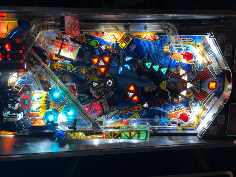
After

Before

Before
Before

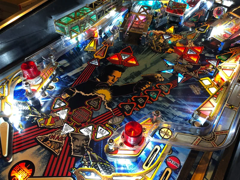
After

After

After

When you Service Bulletin 87 where does the second wire from the connector go? There is a picture on PinSide to explain in more detail what I'm talking about. I was like you. Everyone just said to do the SB when all I think was needed was to check the hand wires first.
Thanks
https://pinside.com/pinball/forum/topic/johnny-mnemonic-is-there-an-owners-club-yet/page/78#post-6799160
Once you've cut the red/brown wires at the connector in the cabinet, you need to splice the loose ends together. Then, run the new wire (connected to J107) into the pin where the red/brown wires were positioned before they were cut. Based on the pic on Pinside, it looks like you cut the wires a fair way away from the connector so you have a long, loose bit. Just cut it off or tape up the end.
Hope that helps!
I'll service apart the glove shortly.
Thanks for your help.
I also have a Johnny Mnemonic pinball.
Now I see that the flippers are moving simultaneously when using the cyberglove; so to say when the hand moves to the right and left respectively.
Do you know about that problem?
In advance thank you!
JP
A couple of things to check. Ensure you have the latest ROM revision. This may be related to earlier game software. Next, check your ball-in-hand switch works correctly as this is how the game knows when to deactivate the flippers.
Hope that helps!