- Published on
Check Your Capacitors! Data East Power Supply Corrosion Repair
- Author
-
-

- Name
- Posts
- Posts
-
I haven't been posting much lately, nor have I been able to take on much repair work due to a house move (more on that later!). However, I've been able to get stuck into a small backlog of board repairs and other minor jobs while I sort out the housing situation.
After the last repair, I thought it would be a good idea to do a short post to remind everyone to check their circuit boards as a part of their regular pinball maintenance regimen. Circuit board parts fail all of the time, but few of these failures will actively damage your machine. Batteries are the most well-known exception and they will certainly damage your circuit boards if they leak. However, fewer people are aware that capacitors are capable of damaging circuit boards in the same way, and should also be checked regularly for signs of damage.
After the last repair, I thought it would be a good idea to do a short post to remind everyone to check their circuit boards as a part of their regular pinball maintenance regimen. Circuit board parts fail all of the time, but few of these failures will actively damage your machine. Batteries are the most well-known exception and they will certainly damage your circuit boards if they leak. However, fewer people are aware that capacitors are capable of damaging circuit boards in the same way, and should also be checked regularly for signs of damage.
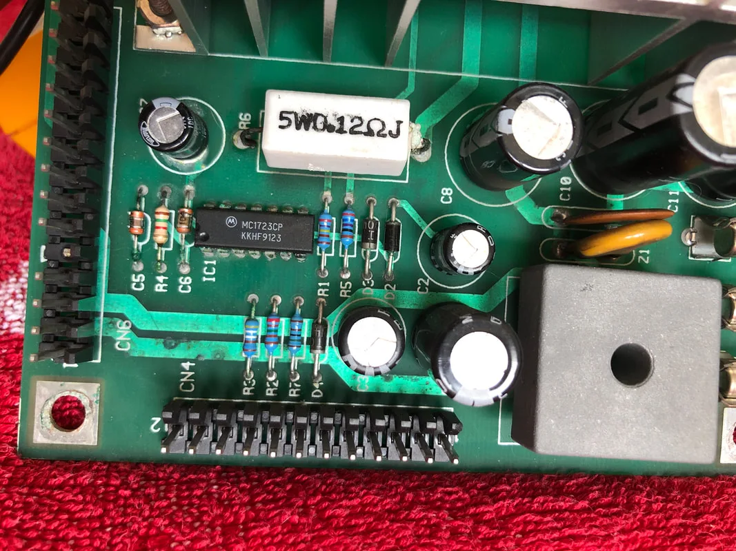
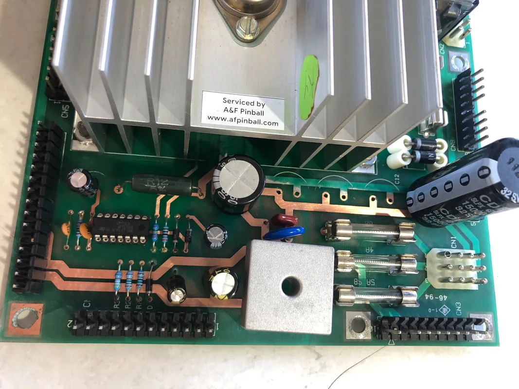
Data East power supply showing signs of damage.

Can you spot the damaged areas on the above board? This is a Data East power supply out of a Mary Shelley's Frankenstein (Sega, 1995). This power supply is the board I most frequently see leaking capacitors on, although Williams power driver boards also seem to be prone to this.
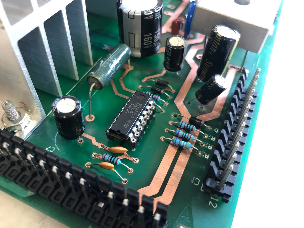
On the Data East board, there are several capacitors in the logic circuit which are prone to spilling their electrolyte all over the components around them, leading to strange game behaviour. In this case, the game would take a long time to boot up, or not boot up at all. This was because the 5-volt circuit was not generating a clean 5-volt signal, which is used by all other boards in the game. A number of components were damaged including the vital 5-volt regulator at IC1 and some surrounding components, which were affected by leaking electrolytic fluid. Without a solid 5-volt output, the MPU will not boot up properly, which is exactly what was happening in this case. So, where was the caustic electrolytic fluid coming from?

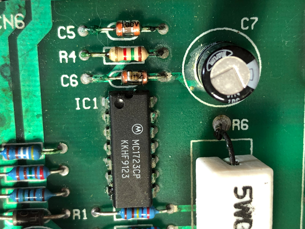
Close-up of the IC1 regulator and nearby components.

Underside of C7 after removal.
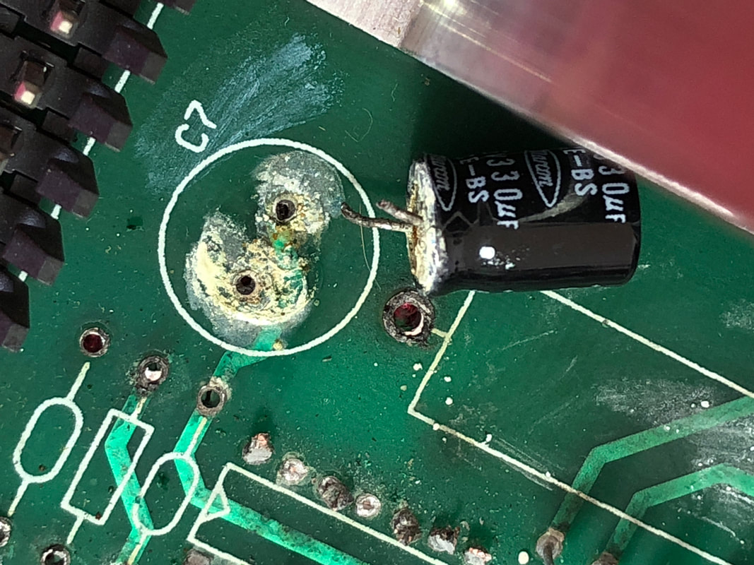
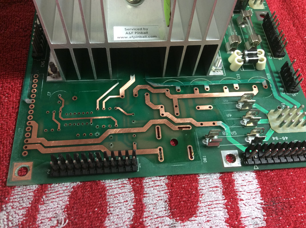
The electrolyte was coming from C7, a 330uF capacitor which also forms part of the 5-volt circuit. Failure of this capacitor will definitely cause issues with the game's ability to boot and play. C7 had leaked extensively. The most visible damage was to the resistors and capacitors immediately underneath C7, but damage actually extended far beyond that. I could see evidence of corrosion underneath the solder mask towards the bridge rectifier at DB1 and even past that to the capacitors at C11-C14. This is all the way on the other side of the board! Corrosion is sneaky like this and can hide under the solder mask in areas far away from the original leaking component. Make sure you check boards thoroughly for any dark or discoloured spots along the green solder mask.

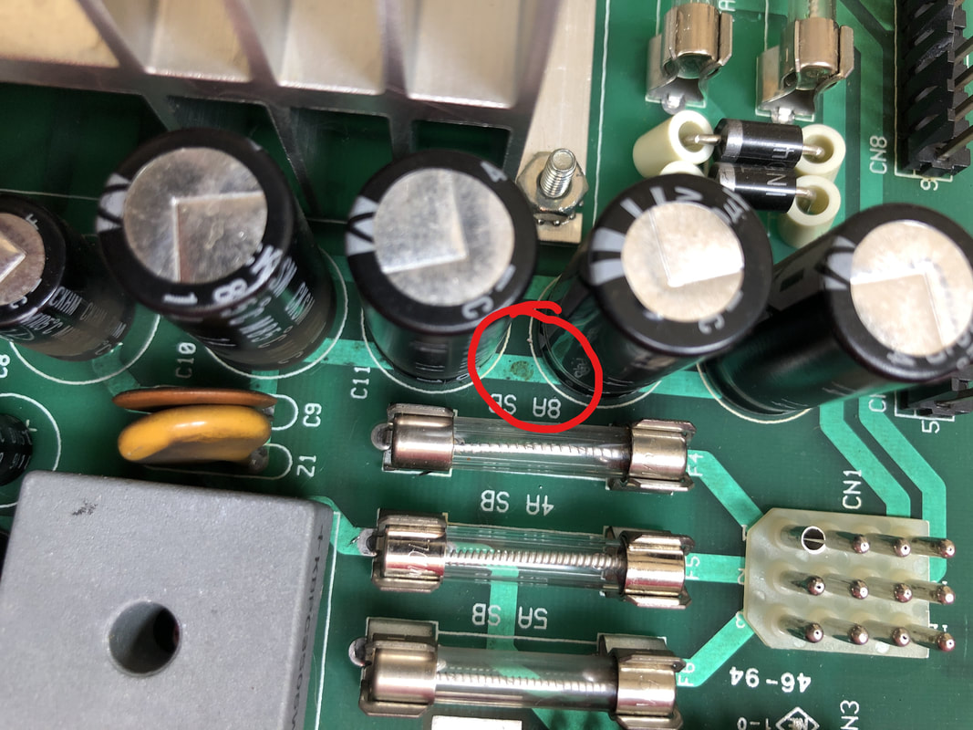
Corrosion affecting components as far away as C11-C14.
So, what to do next? Terry B's guide to repairing alkaline damage is probably the most comprehensive resource available for this type of repair, and is thoroughly recommended reading before commencing on this kind of repair.
I followed a simple process of:
- Component removal
- Abrasive removal of all traces of corrosion with sandpaper, including sanding back of the green solder mask
- Cleaning with vinegar and alcohol
- Replacement of affected components
- Coating board with conformal coating
I have covered the above steps in detail in another blog, so I won't repeat them here. However, I will say that making sure you thoroughly sand the board back to the bare traces is vitally important. Leaking electrolytic fluid is like cancer, and will spread unless absolutely all traces of it are removed. There's no harm in performing additional acid and alcohol flushes to make sure the board is fully clean.

Image of the board after affected component removal and sanding down to the copper traces.
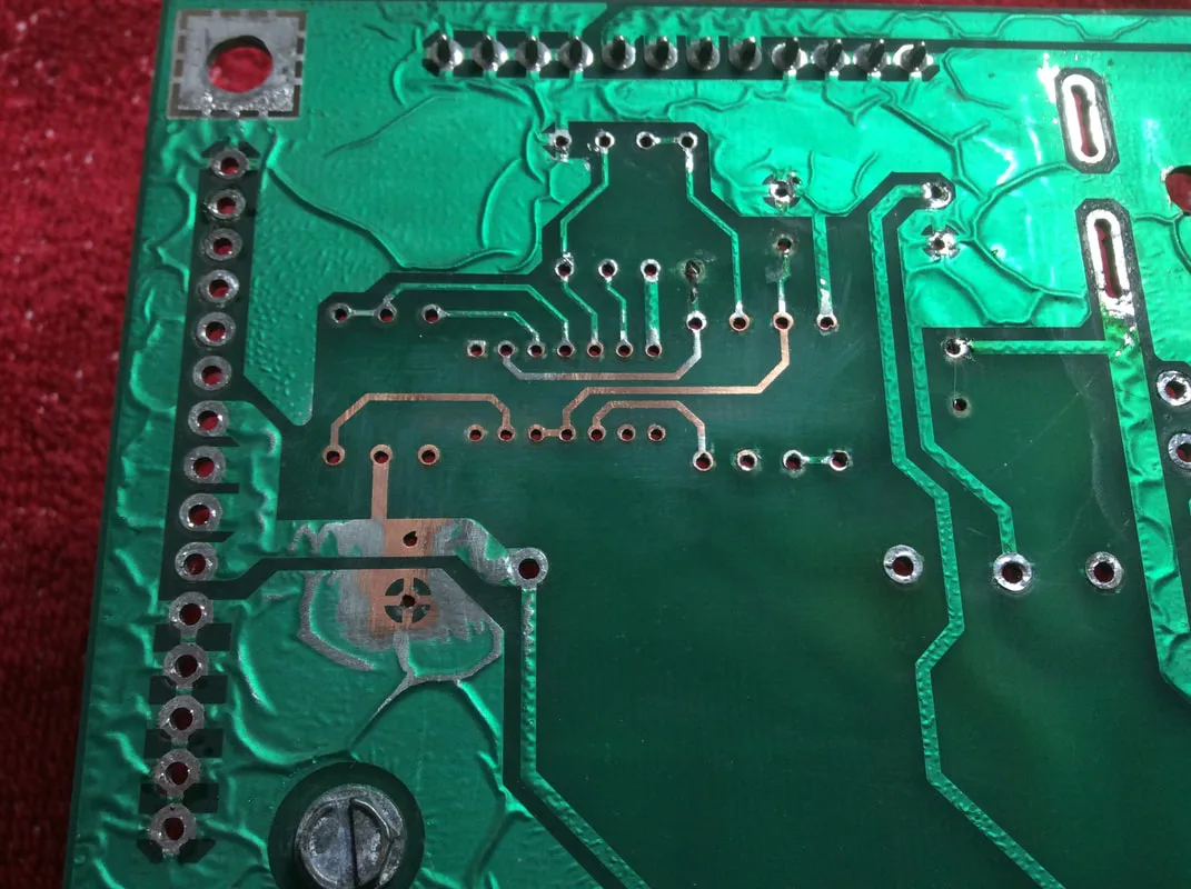
As the corrosion was quite severe, the rear of the board was sanded, too.

Once the board was clean, I covered it with a layer of conformal coating (Jaycar). This will seal in the repaired area and prevent the exposed copper traces from oxidising. At this point the board was ready for repopulation. Bit first, a couple of notes about repopulating components on these Data East power supplies.
The original bridge rectifier at DB1 has thick lugs for component leads that slot into giant holes on the board. I hate this type of rectifier as it is impossible to remove from the board. You can't easily remove all of the solder from the lugs, so it can never simply be desoldered and plucked from the board. Instead, I cut each of the legs off with a Dremel (or similar) tool, and then desolder them individually. This process is fiddly and the board is a mess of metal shavings afterwards, but it is the safest way I have found to remove these rectifiers. I replace them with wire lead bridge rectifiers (RS Components, RTBB, Mr Pinball) as these are much easier to remove in future if necessary, and are the same type as used on Williams boards, so I don't need to stock multiple types.
The capacitors at locations C11 to C14 are 4700uF, 25-volt capacitors. These can actually be replaced by a single 18,000uF capacitor, or a more commonly available 15,000uF capacitor. I replaced them with a 15,000uF capacitor (RS Components, RTBB, PSPA, Mr Pinball) as these are the same capacitors used on Williams power driver boards, so I always have some on-hand.
There are a couple of components which are more difficult to replace. The resistor at R6 has a tiny resistance of 0.12 Ohms but must be rated at 5 watts. The most economical replacement I found was a 7-watt wirewound resistor (RS Components). It looks a little different but works just as well as the original.
Components at Z1 and C9 can also cause some confusion. C9 is a simple 0.1uF ceramic capacitor, but rated at a massive 200 volts! I replaced this with a polyester capacitor rated slightly higher at 250 volts (RS Components). Z1 is labelled cryptically on the schematic as "15G470KM". While the Z1 designation may suggest that this is a Zener diode, it is actually a varistor. It was difficult to make out the markings on my original varistor, but suffice to say it is nominally rated at a somewhat odd voltage of 47 volts (RS Components).
Board repopulated with new components.

Side view showing C7 and surrounding components.
Once the new components were installed, the board was ready to be put back into service. When it was installed back into Frankenstein, the game booted immediately; much better than the ten-minute boot times it was suffering through previously!
So, what is the moral of the story here? Check your circuit board for evidence of leaking capacitors just like you'd check them for leaking batteries. If you find evidence of damaged capacitors or the characteristic green "fuzz" of electrolytic fluid, it's time to pull the board for repairs, or give somebody a call who can do them for you!
2 Comments
Hi great reaading your blog
I appreciate this detailed explanation about capacitor failure and its impact on pinball machines.