- Published on
WPC display driver board integrated circuit replacement
- Author
-
-

- Name
- Posts
- Posts
-
Up until recently I had been putting up with some strange display issues on my Doctor Who (Bally, 1992) and Judge Dredd (Bally, 1993). Each game worked well enough but there were artifacts on the display that should not normally be present. Since I was about to sell the Doctor Who, I decided to finally figure out the issues with both display driver boards. I also figured it would be a good opportunity to write a general instructional post about integrated circuit replacement on a circuit board.

The WPC dot matrix display driver board.
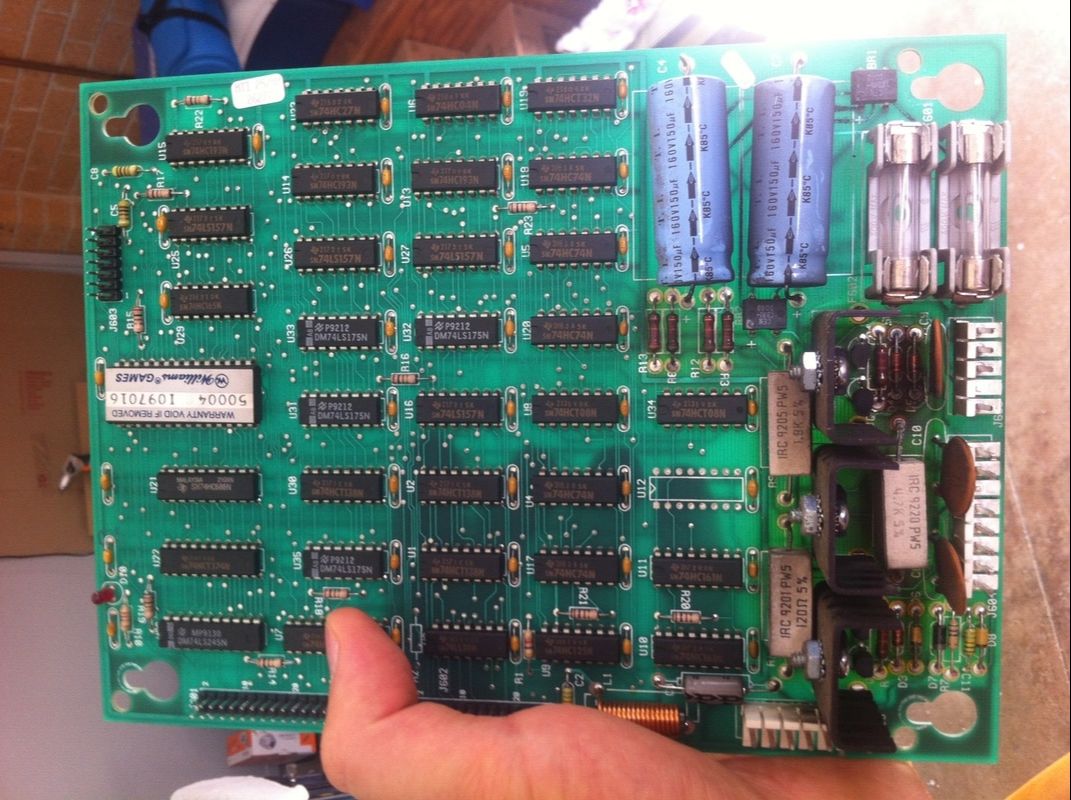
The DMD driver board is the circuit board that controls everything to do with the plasma display. Most of the problems with these boards are associated with heat damage on the bottom half of the boards. These areas heat up due to the high amount of current going through to the display (over 100 volts) and stress on the components over time. It's quite common to see damage to these boards that makes you think they've caught on fire! If you see the voltages supplying the display starting to go out of spec, then it is likely an issue with one of the components in the high voltage section at the bottom of the board. I deal with rebuilding this part of the board in another blog post.
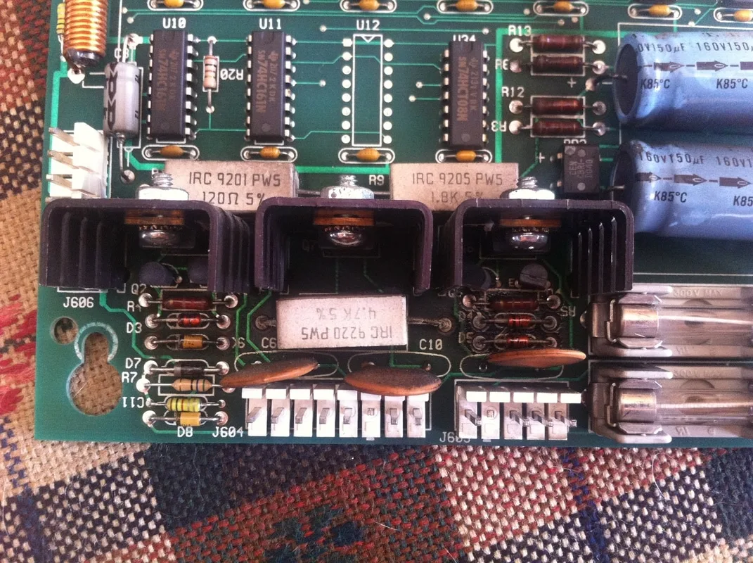
Close-up of the high voltage section of the display driver board. Note the heat damage around the resistors.

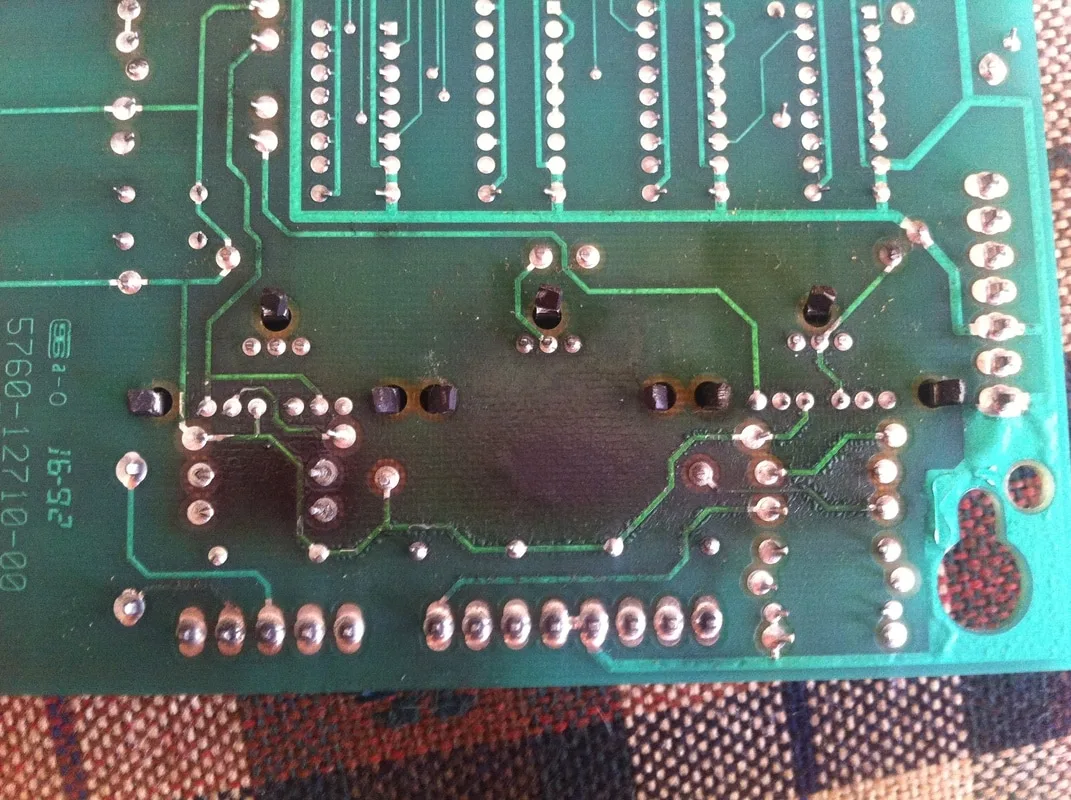
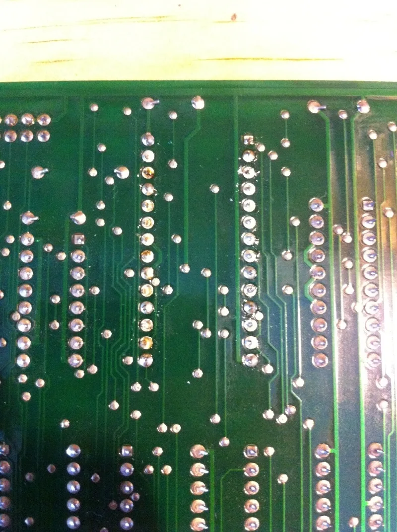
This is the underside of the high voltage section. The heat damage is much more evident here.
So, was the high voltage section the cause of my display issues? No. The display voltages were all as expected and the artifacts on the display were not consistent with a failing high voltage section.
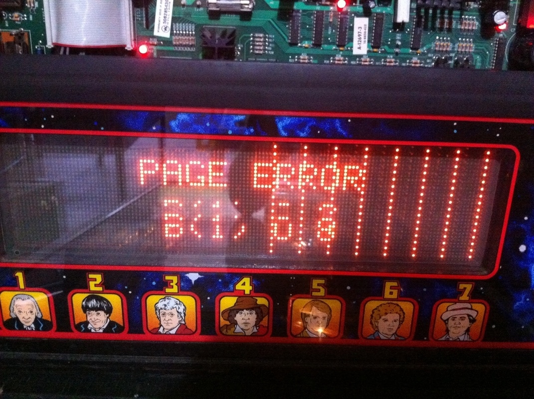
I took both boards and installed them into the Doctor Who for testing. When troubleshooting any display issue, put the game into display test mode and see if any errors show up. This can make troubleshooting much simpler. This is what I saw after testing each board. Neither of them could successfully complete the display test.

Paging error on DMD driver board no 1. Vertical lines on the right half of the display.
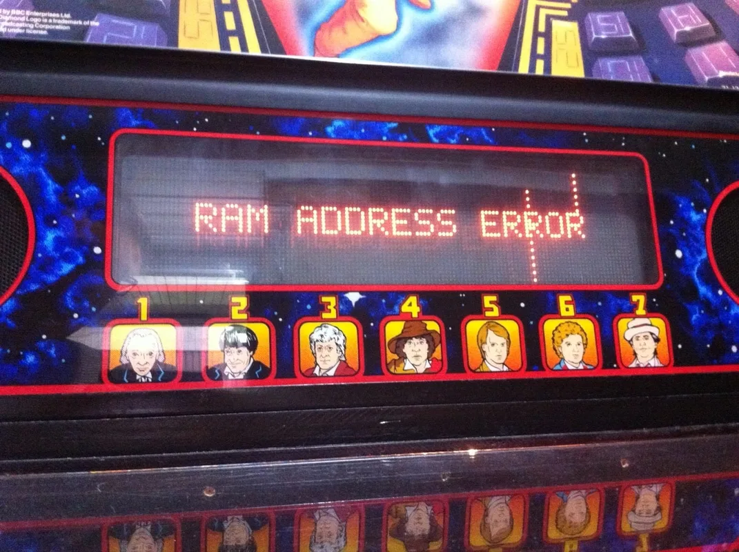
RAM address error on DMD driver board no. 2, with two vertical lines.

Pinwiki has some great descriptions about what you can expect to see when various display driver components fail. In fact, the issues on my boards were very similar to those depicted in Example 2 and Example 4 on the Pinwiki page linked above.
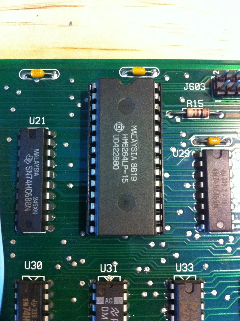
Both of the errors were suggestive of faulty RAM. The second error even mentions the RAM specifically. The display board has several integrated circuits on the board, but 99% of the time just one of them is responsible for display issues. The problematic IC is U24, located at the top and centre of the board. This is the one normally covered by the warranty sticker.
So, the first step was to order some replacement ICs. Various Aussie pinball retailers sell them, including Pinball Spare Parts Australia and John's Arcade. There are also several general electronics retailers that sell them, including Futurlec and Rockby. You can even buy them quite cheaply on eBay. Thankfully, they are a fairly available component. I am very grateful to John (John's Arcade) for supplying me with two sets of U24 chips and sockets. Now it was time to heat up the soldering iron!
The first step is to cut the chip from the board. Use some fine/precise wire cutters or similar tool as it is fiddly getting in between the IC's legs. Don't bother trying to desolder it intact, as this will not be easy, not to mention pointless if the chip is faulty! If the chip is particularly valuable (or irreplaceable), then you can skip straight to the desoldering step. However, whenever desoldering an integrated circuit while leaving it intact, you risk damaging the traces and through holes on the board as it is very hard to remove all of the solder from the joints.

Removal of the U24 chip, leaving the legs/pins behind.
Next, you will need to remove the pins that are still embedded in the board. Using a desoldering gun, hold the gun tip over the through hole you wish to clear, wait for the solder to melt, then suck it up. It's best to do this from the component side of the board, as the chip legs are thicker towards the top, and this thick part may not pass through the through hole if you try and suck it out from the underside. Be quick and precise with this as you don't want to heat the area for any longer than absolutely necessary. Heat destroys through holes and vias!
Alternatively, you can do this with a manual solder sucker. Simply hold the solder sucker against the joint you wish to clear on the component side of the board. Or, even better, get someone else to do this for you. Heat the through hole you wish to clear with a soldering iron on the other (underside) of the board. Once the solder melts, simply press the button on the solder sucker to remove the solder.
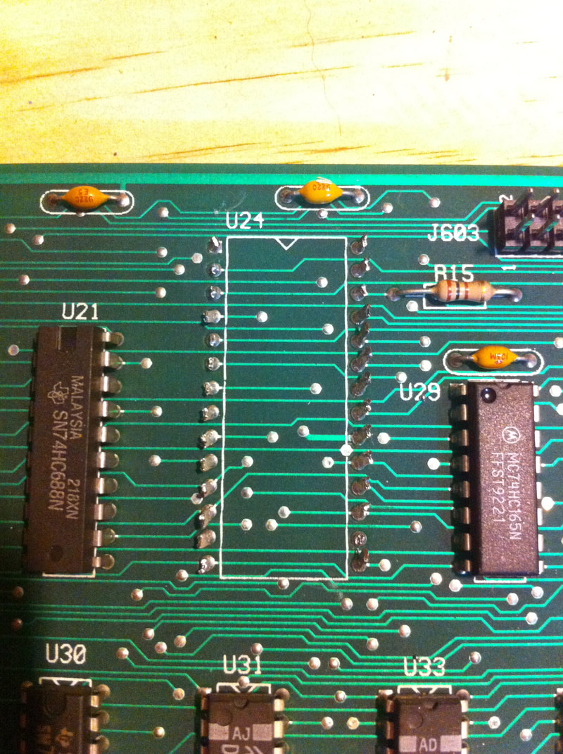
You may find that component legs stay stuck in the through hole, attached by a tiny sliver of solder that you can't remove. In these cases, you can pull the leg out manually with some tweezers or fine pliers. You may need to use a little force, but the leg should come loose with only a little effort. If it's not budging at all, you will need to remove more of the solder holding it in place. You can add more solder to the joint to help you suck up smaller amounts of solder that are being stubborn. Don't forget to check your desoldering device for legs and debris that have been sucked up and become lodged in the device shaft. You should be left with a nice clean board, with clear through holes. Hold the board up to the light to check that there is nothing blocking the holes.
After removing the old solder, hold the board up to a light source to check for clean through holes.

As a rule, always install integrated circuits into a socket before installing them into the circuit board. This makes them easy to replace in the future. Turn the board upside-down and hold the socket against the board with tape or some kind of support underneath. Then, simply heat up the socket's pins with the soldering iron, add some solder, and voila! Use enough solder to surround the component leg and fill the through hole, but no more!
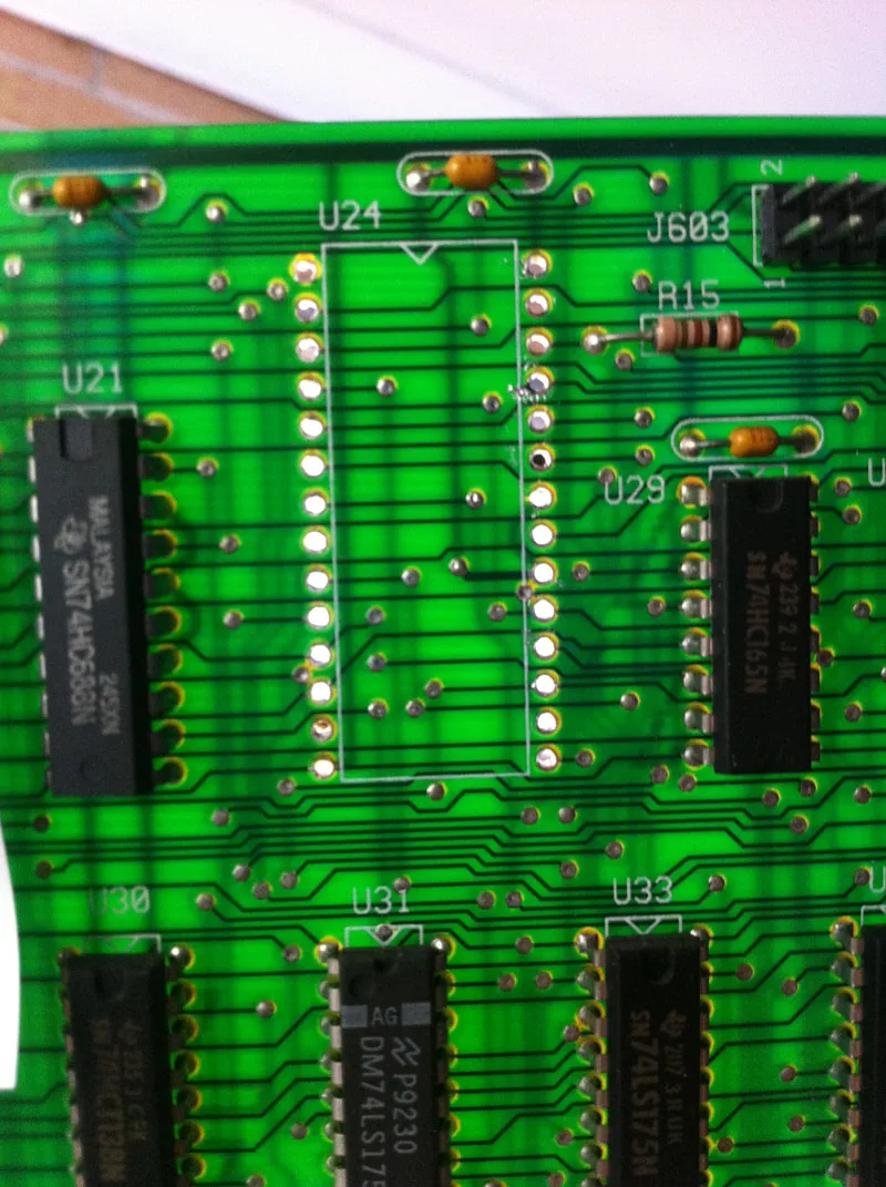
Topside of the board with the new socket and IC installed. All done!
Underside of the board with new socket and IC installed.

And in this case, that was about all I needed to do! I reinstalled each board into the Doctor Who and noticed that none of the display artifacts were present. Then I ran a display test, and each board passed without issue. So, U24 was the issue on both boards. Board repair success!
0 Comments