- Published on
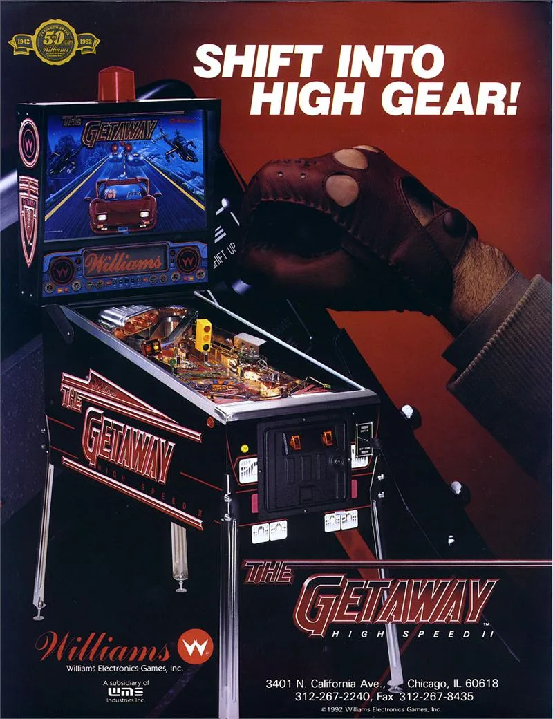
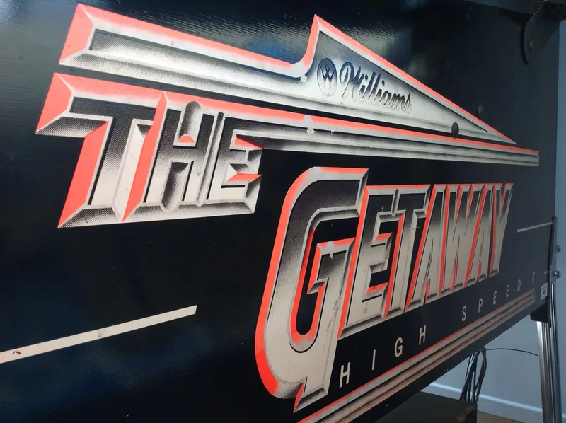
The Getaway: High Speed II
- Author
-
-
- Name
- Posts
- Posts
-
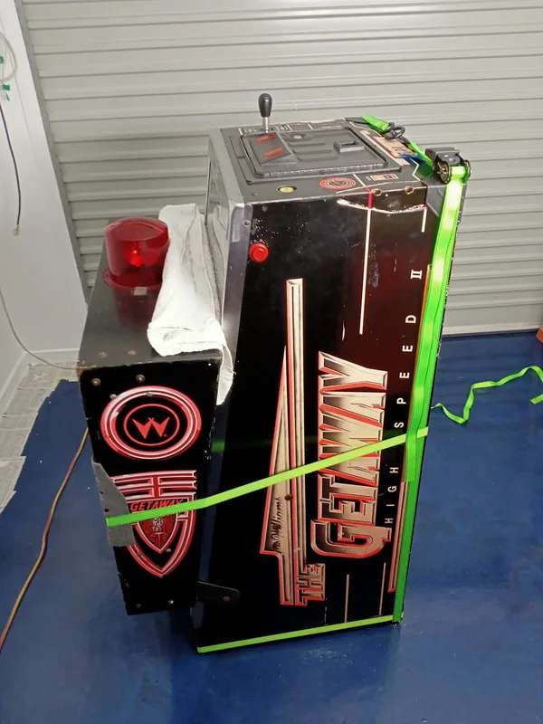
Ever since I became interested in pinball, I had always wanted to play and own a Getaway: High Speed II (Williams, 1992). The Getaway is a popular machine and over 13,000 were made. As a result, I had played a few in private collections, and had a blast each and every time. It's an incredibly fun game that has wide appeal. Having only just finished restoring my first machine, I was game for another. I contacted a seller in north-western Sydney who was selling a Getaway. She and her partner had had the game for several years, but it had never been set up. Her husband had purchased it from his place of work, where it had been sitting around and was no longer wanted. The couple originally intended to have it repaired, but now they were moving house and needed to get rid of it.
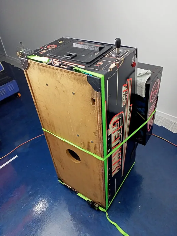
The first image I saw of the machine.

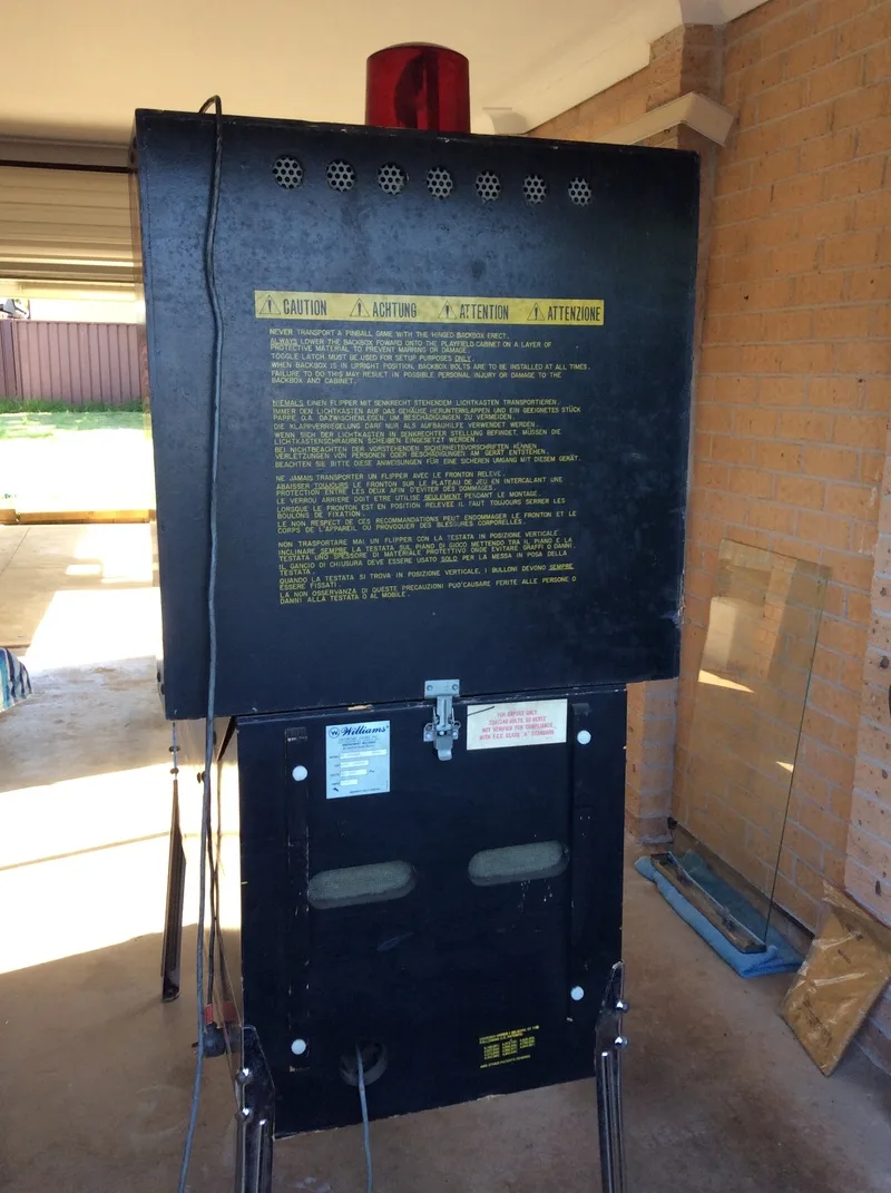
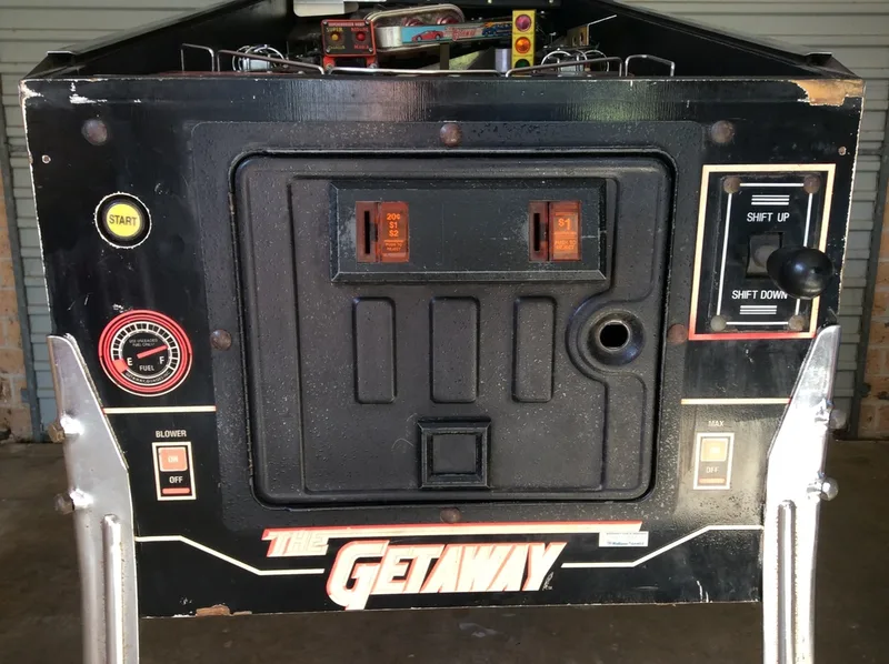
Above is the only picture I saw of the game. There's not a lot of information to glean from a photo like that! This was a tricky machine to inspect for a couple of reasons. First, it only had two legs. Everything had to be done with the machine flat on the floor. If you ever need to inspect a machine like this, wedge something under the front of the cabinet so you can still get to the power switch. Second, there were no keys for the cabinet or backbox. I wasn't able to get into the machine to actually inspect it. Here is what I saw from the outside:
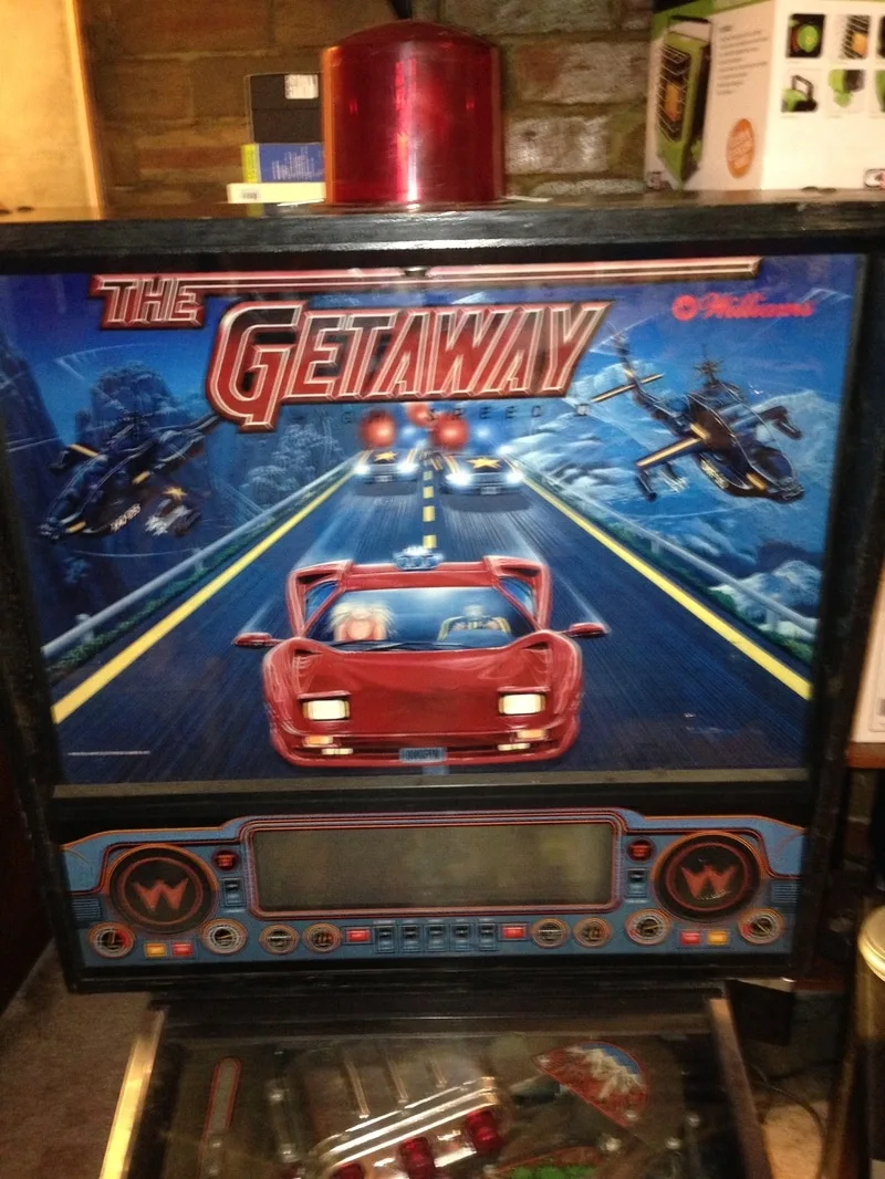
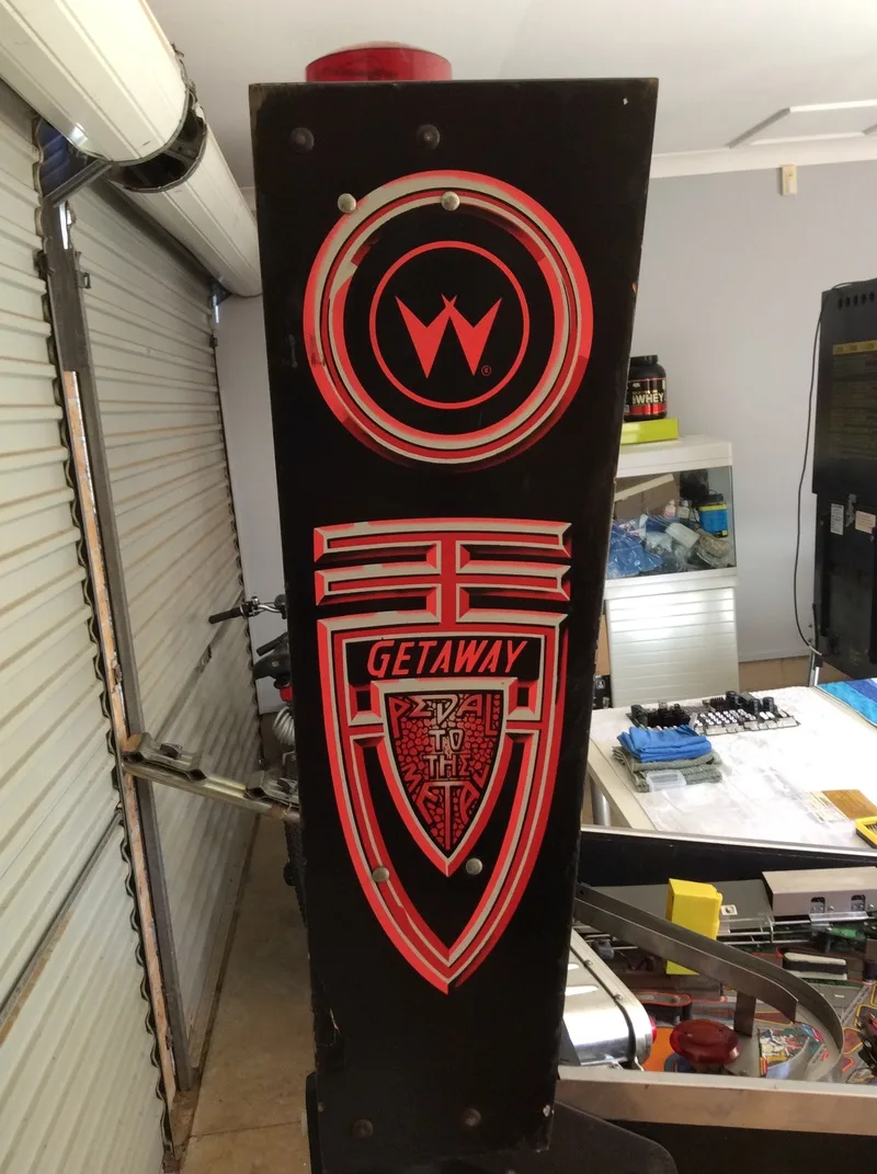
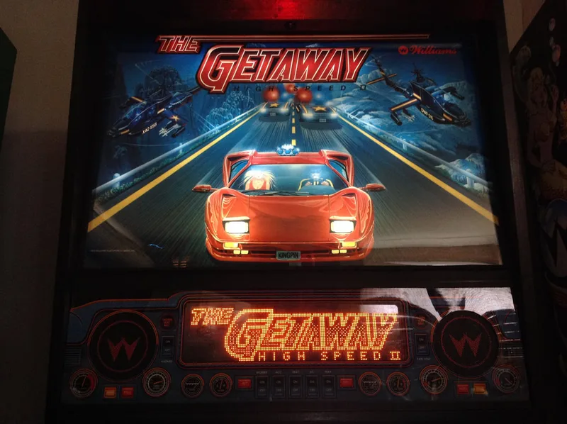
Backbox and Translite with dome topper.


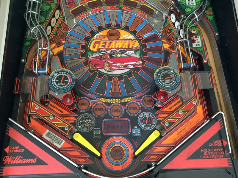
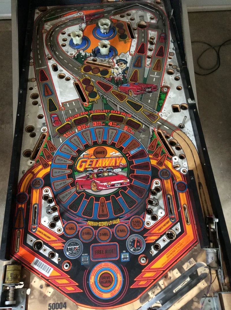
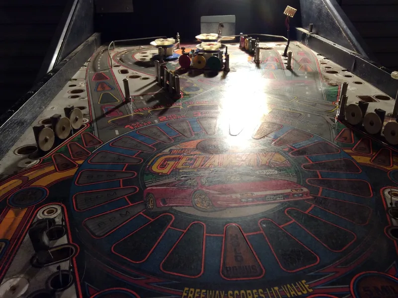
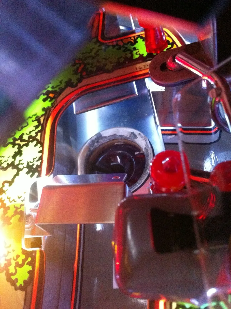
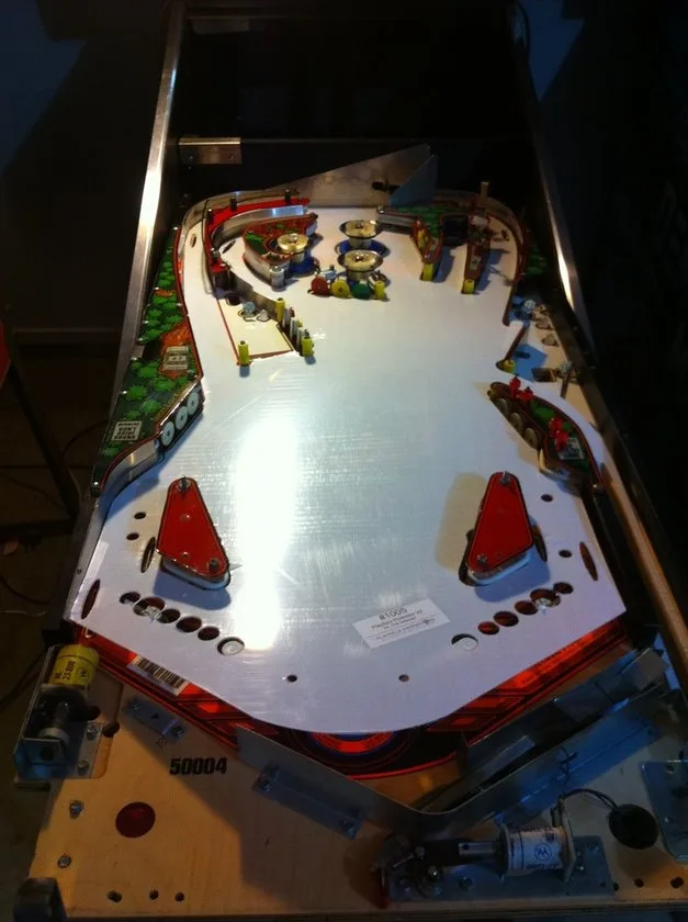
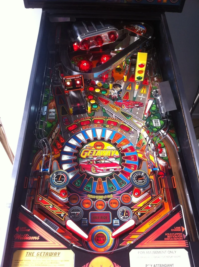
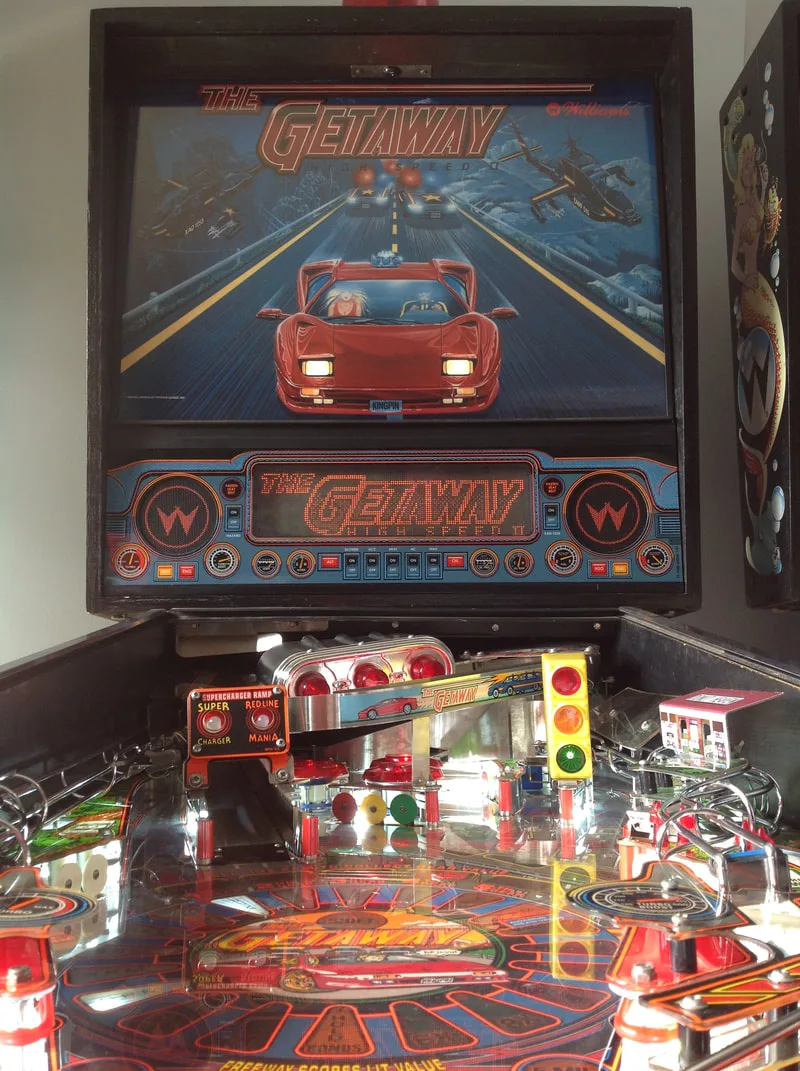
Full playfield view.
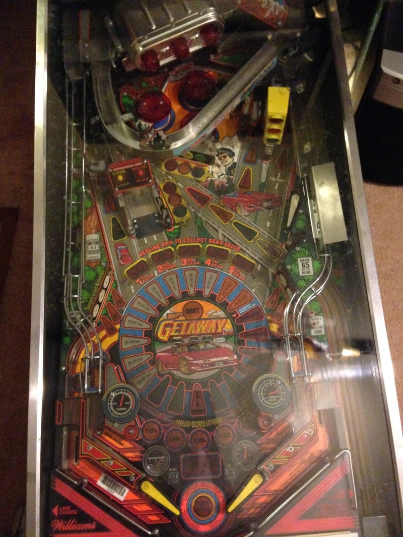
Playfield close-up. Ball track marks everywhere!

Luckily, the owner had told me about the missing keys before I arrived, so I came prepared. I brought a drill to drill out the lock and get into the coin door. I followed the basic instructions from this video guide, which explains how to drill out a coin door lock. However, don't do what I did and bring standard steel drill bits. As much as coin door locks look like poor quality locks, none of my steel bits could actually penetrate through the tumbler. I had to borrow a titanium bit from the owner to punch all the way through. So remember to bring a good battery-powered drill and strong drill bits! Once I got into the coin door, I found the backbox keys, so I then had access to the full machine. The owner didn't know much about the history of the machine, but I could tell that the machine had been sited at some point in the past from the instruction cards.
Initial condition report (click on sections below to view details)
- Timber in good condition. Some small scuffs and marks. Some screws used to fasten the right side of the cabinet to the base.
- Decals in poor condition. Major fading. Artwork worn away near flipper buttons.
- Translite in good condition.
- Two legs missing.
- Topper in good condition.
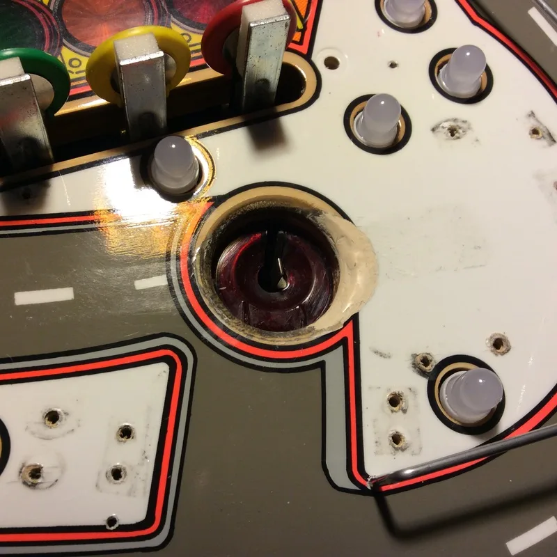
- Playfield was very dirty.
- Consumables (rubbers and lamps) dirty and in poor condition.
- Playfield artwork in average condition. Some inserts raised. Some with worn decals.
- Plastics in average condition. Supercharger entry ramp plastic broken.
- Playfield mechanisms/toys in average condition. Two ball guides by the right freeway orbit and one by the left freeway orbit were missing. Wear at the tunnel saucer.
- All mechanisms and assemblies very dirty.
- Consumables (coil sleeves, flipper parts) dirty and in poor condition.
- Machine would not boot!
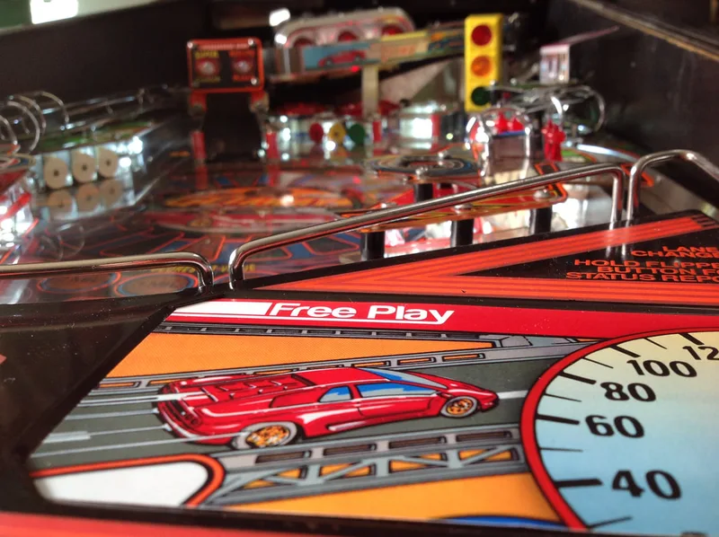
Externally and internally, the machine looked okay. The cabinet decals were faded, but I have never seen a Getaway with the original red colour fully intact. The two missing legs were a little odd. How does a pinball machine lose half of its legs? Who knows. The playfield looked like it would clean up nicely and most of the parts were there. The biggest issue was that the machine would not turn on. I tried a few different things to get the machine working on the spot, but none of them worked. I was stumped.
I had no idea what was wrong with this machine and, for all I knew, the fix may have been totally out of my league. Luckily, the seller acknowledged this and offered me a good price. I bought the machine knowing full well that it had potentially massive faults requiring repair. If you find yourself in this situation and you're unsure if you can fix the machine or not, just buy it! The worst case scenario is that the fault is major and you will have to pay someone more experienced to fix it. If that's the case, you'll just end up paying the same amount in repairs as if you bought the machine fully working. The best case scenario is that the fault is minor, and you just saved some cash. Win! We paid the owner and brought the Getaway home to tear apart and have a closer look.
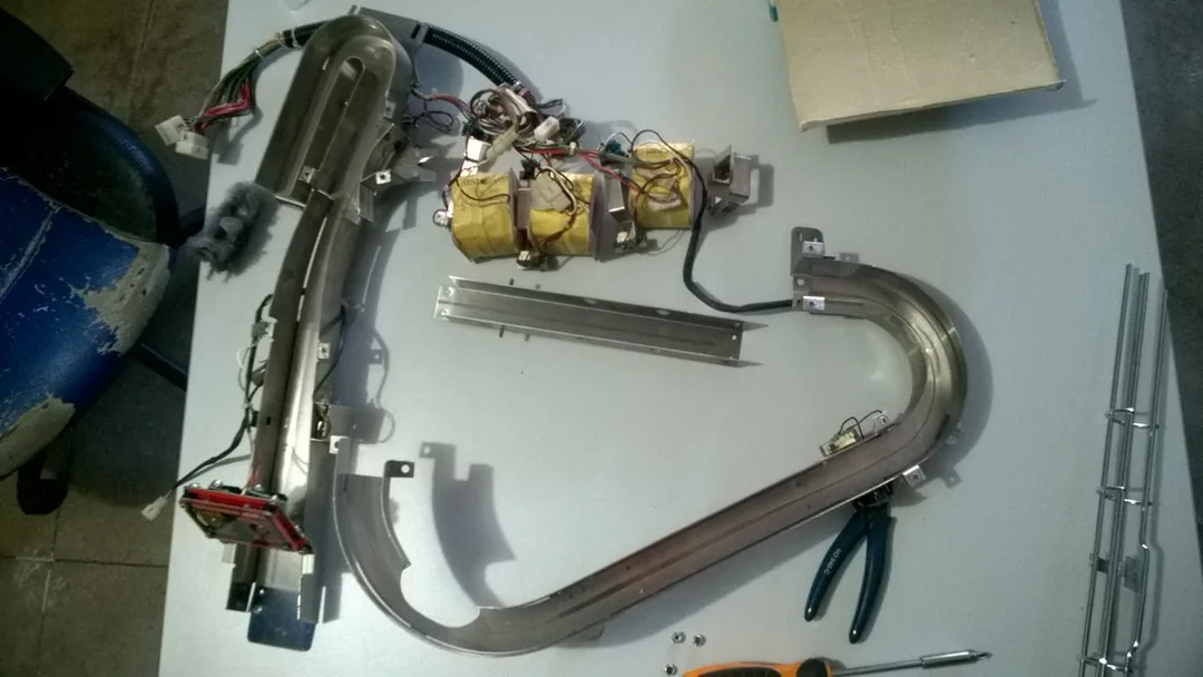
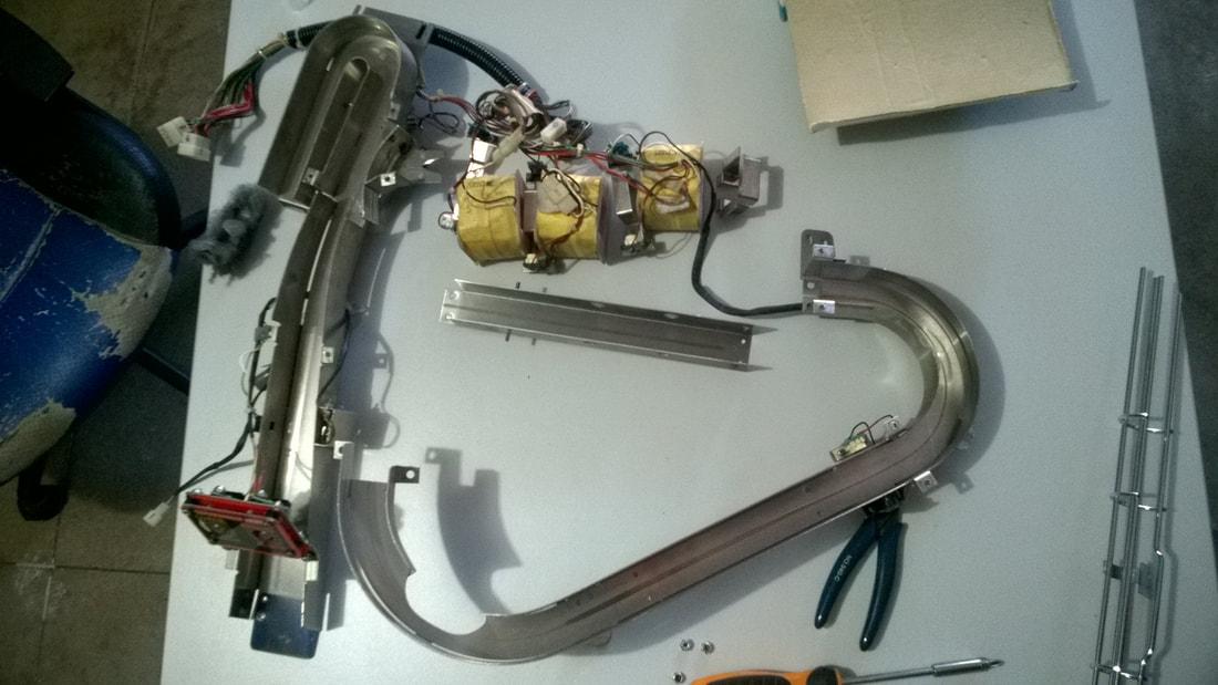
Disassembly
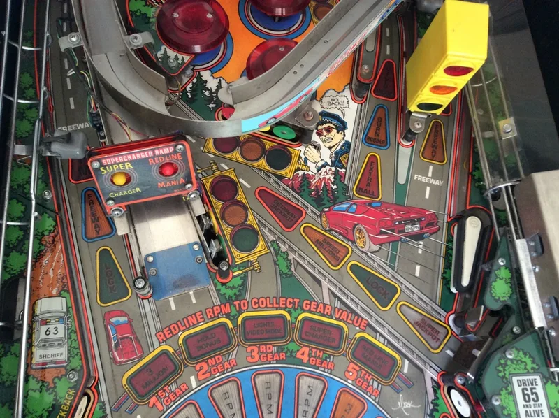
The Getaway is a nice machine to tear down because it has a fairly simple, single-level playfield with only the supercharger and two ramps coming down either side of the playfield. Take these off first, and removal of other playfield components is self-explanatory. The trickiest part of disassembly is the supercharger. This tutorial is helpful, and has pictures that guide you through the process.
Tips & Troubleshooting (click on sections below to view details)
I actually mistakenly replaced the EMI filter first, thinking that this was the problem, but when that had no effect, I looked more closely at the terminals and found the problem. Most of the parts in this box are susceptible to damage from surges, and they need to be replaced when damaged. All are available locally including the EMI filter (Jaycar, PSPA), thermistor (PSPA, Mr Pinball), and varistor/MOV (Jaycar, PSPA, Mr Pinball). If using the Jaycar line filter, note that the case of the filter is plastic and you will need to run a separate wire to ground the line filter. Original line filters were metal and the case of the filter grounded it to the chassis without the need for a separate wire. Another important note about the Jaycar line filter. It is pinned oppositely to the original line filter. The LOAD side of the Jaycar line filter has three terminals, and the LINE side of the filter has two terminals. The LINE and LOAD sides are indicated on the schematic printed on the filter. So, you cannot simply insert the new line filter in the same orientation as the old one (the game will actually work in this configuration but the line filter will not be doing its job). Ensure the LINE side of the filter is connected to the incoming active and neutral, while the LOAD side (with three terminals) is connected to the power switch. The third terminal is the earth/ground, which must be connected to the metal box chassis. It's a bit weird that the earth is mounted on the load side of the filter, but that's how they designed it!
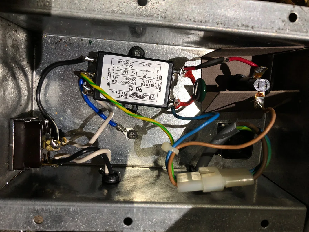
View of the line filter box showing new line filter and soldered power switch.

The varistor and thermistor are important parts of the game's surge protection circuit. Be careful if ordering these parts from US suppliers, as the EMI filter and varistor must be rated for 240v. Pinwiki had a good explanation of how to check them. Whenever working on this part of the game, make sure the power cord is unplugged! All components up until the power switch are live when plugged into a active power outlet and you don't want to be sticking your fingers in here until it's safe!
Extract from the Getaway operations manual showing the tantalum capacitors mounted to the sound board.


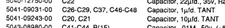
View of the new C47 capacitor with the burn marks and damage from the previous one still visible.
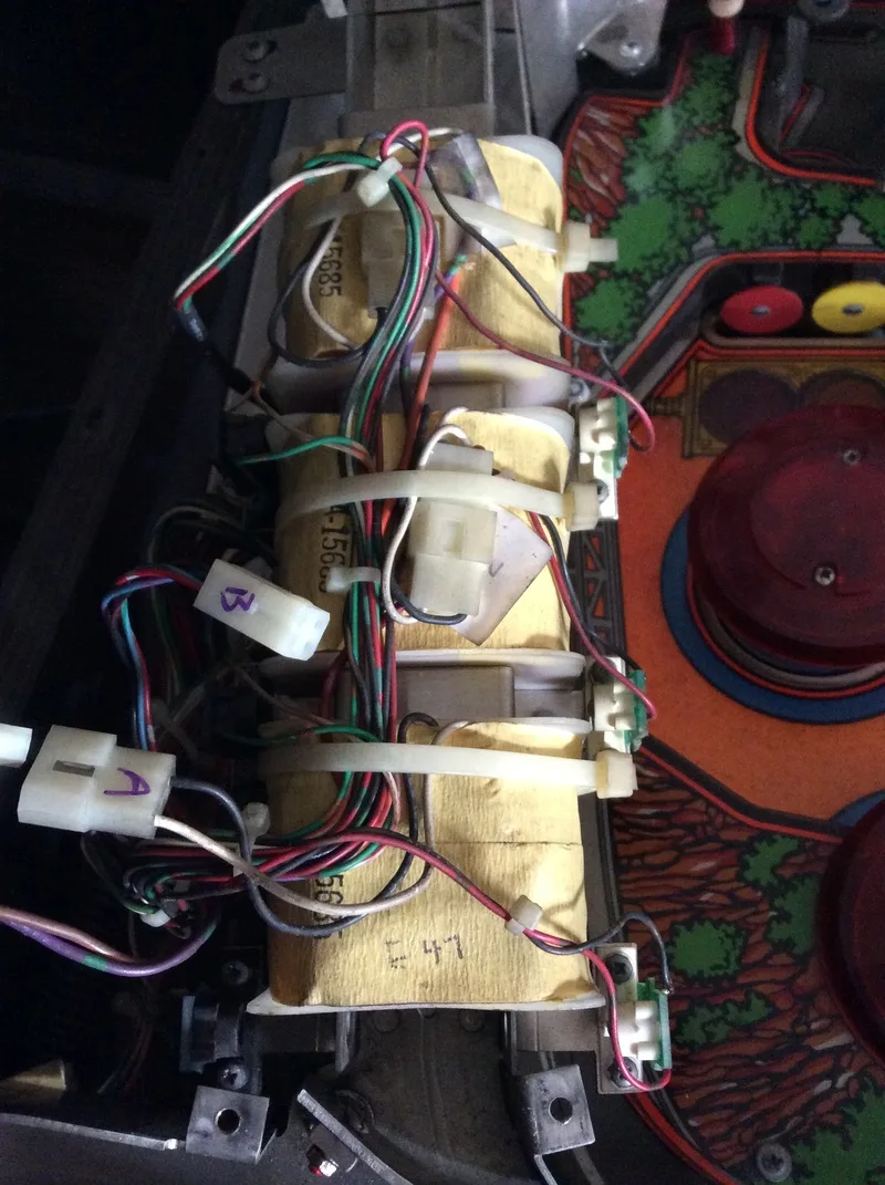
The hole through which the supercharger wiring goes is at the top left.
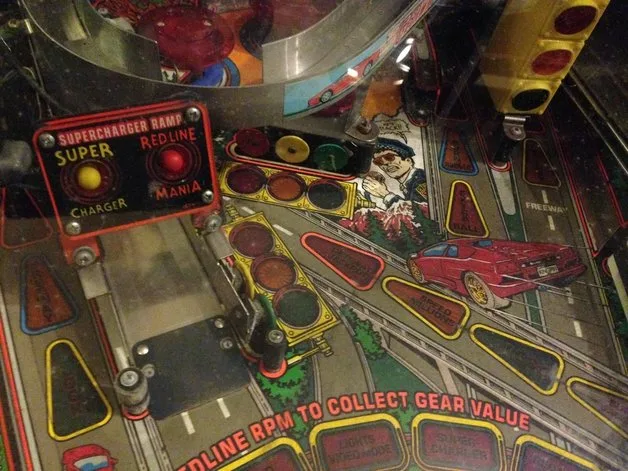
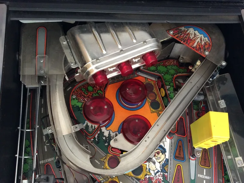
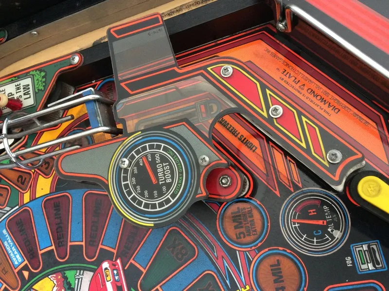
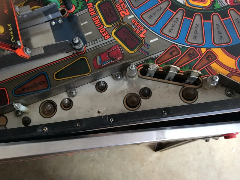
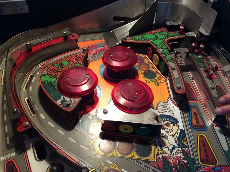
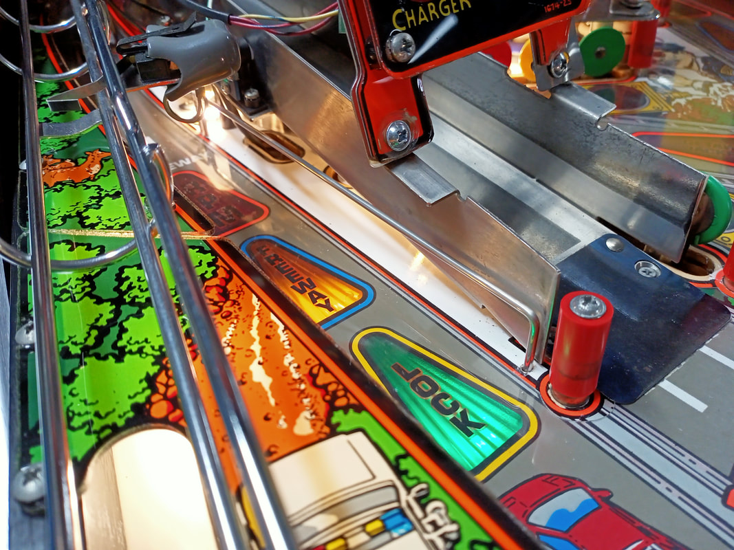
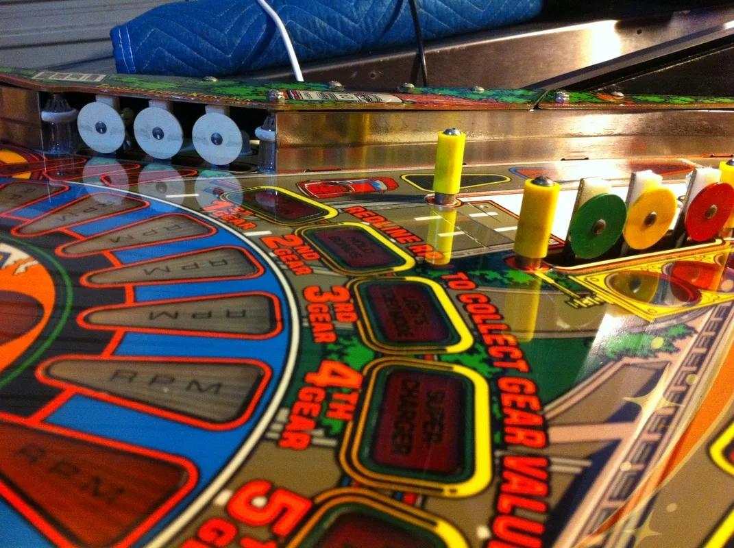
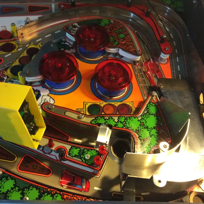
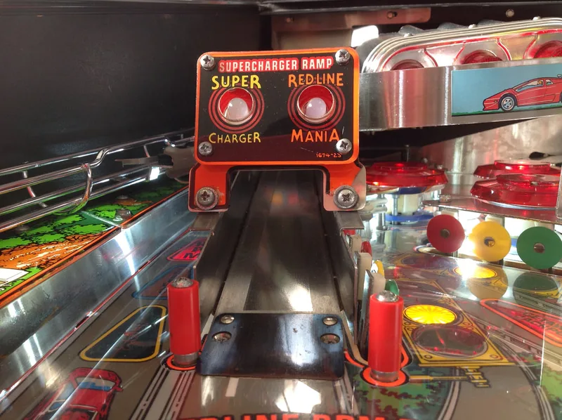
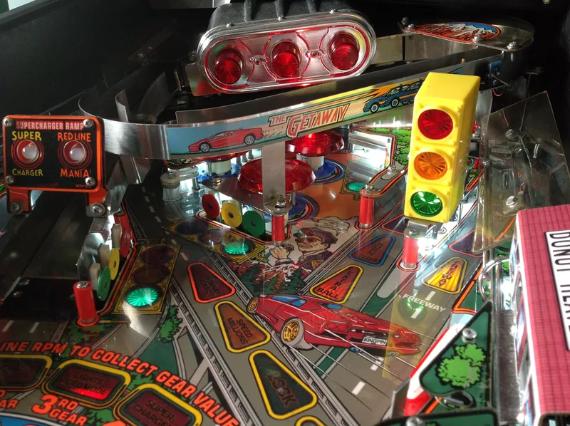
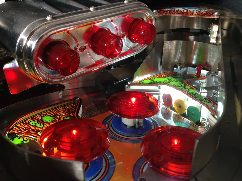
The supercharger is the main playfield toy on the Getaway, so make sure you give it a proper clean. Wipe down the metal runway and guides, the three magnet assemblies, and service the coil assembly that controls the diverter (a good clean and a new coil sleeve at the very least). If you don't clean the coil assembly, you might find that the diverter is too slow to open or close, which makes balls skip the supercharger entry, or pushes them out too early. After a thorough clean the Supercharger was working like new again - balls were whizzing around faster than I had ever seen on any other machine! You need to pull the supercharger entirely apart to clean out the accelerator tray, which is where the magnets sit. Polish the supercharger as much as possible with a metal polish to really make it slick.
Fully disassembled supercharger assembly, ready for cleaning.
Here's a video of the supercharger speed test once I got most of it back together. It was bottoming out at around 70 ms - super fast!
There's one other problem that seems to plague most Getaway owners and robs the supercharger of a lot of speed. The diverter (part no. A-15801 on most supplier websites, but listed as A-15586 in the manual) was originally riveted together with two rivets. The bottom rivet was recessed into the diverter face, allowing it to sink into the diverter and not protrude. This allowed the balls to whizz past at full speed. The diverters commonly break at these rivets and are often fixed using screws and nuts. This holds everything together, but often the screw head will stick out and will nick the ball as it comes past. This will rob the ball of some speed, depending on how much of an obstruction the screw head is. My diverter was repaired in this way and the top screw head was sticking out so far that it impacted the ball's speed. Screwing it back in tightly gave enough clearance for the ball to pass cleanly. If your diverter is beyond repair and you aren't able to rivet it together, brand new ones are available (PSPA).
Screws protruding from the face of the diverter.


Underside of the supercharger assembly showing the diverter coil assembly.
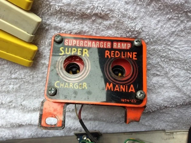
The cracked supercharger ramp entry plastic from the game.
I was curious as to how this plastic could get broken as I never seemed to see balls hitting it. I set up a slow motion camera (actually an iPhone 8) and recorded the area to see what would happen. Sure enough, after a few hits to the standup targets, I saw exactly how this piece gets broken. Airballs from these targets get sent right into the side of the supercharger ramp where this plastic sits. No wonder it got smashed!
To stop the airballs, I bent the supporting brackets behind each of the standup targets downwards slightly. This deflected balls downwards towards the playfield instead of upwards like before. The airballs stopped after that.
Bending the support bracket of a standup target to deflect balls downward.

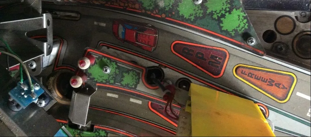
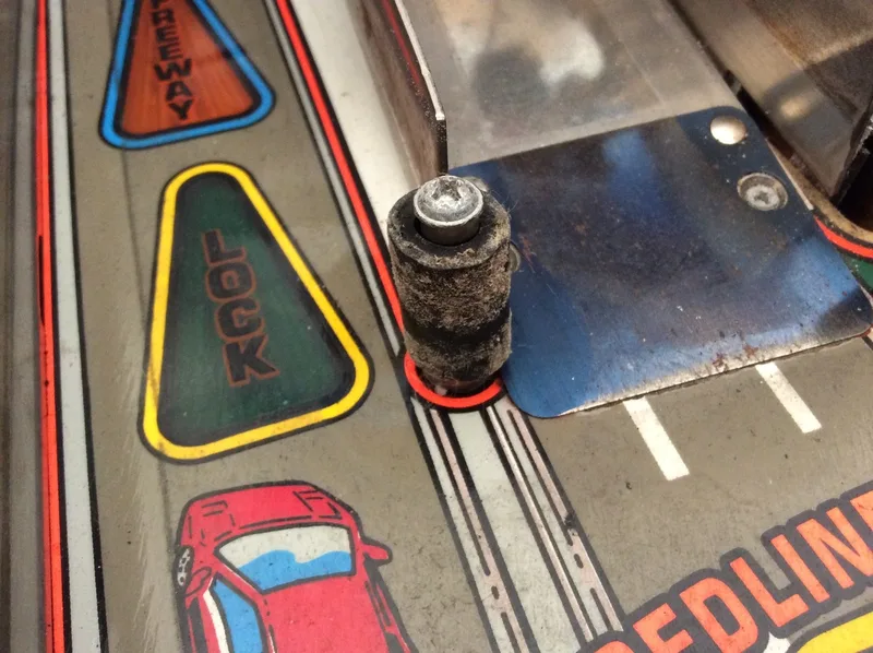
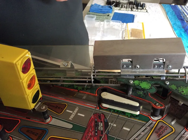
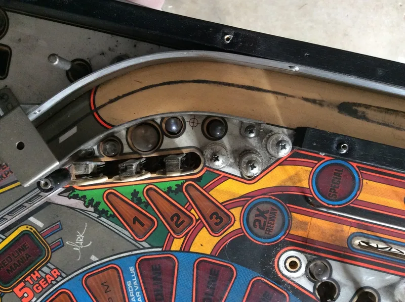
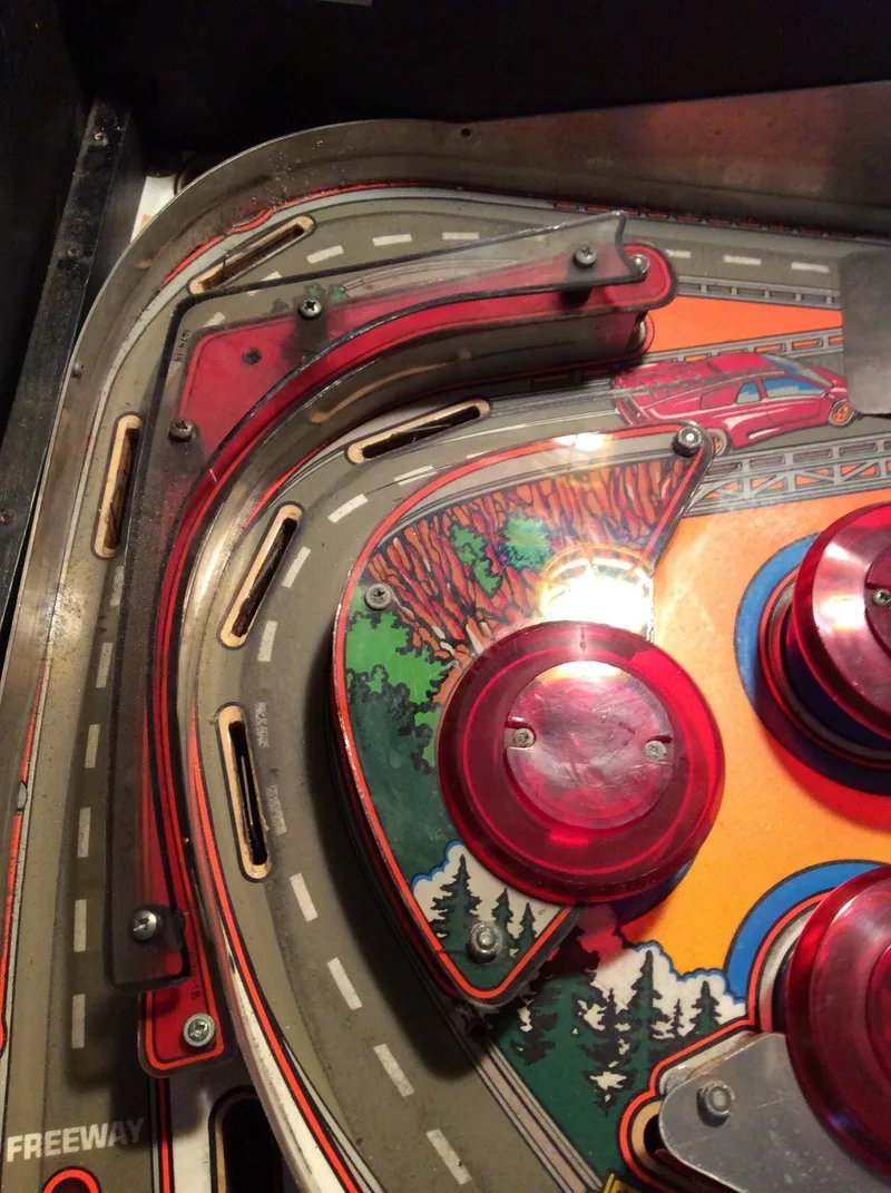
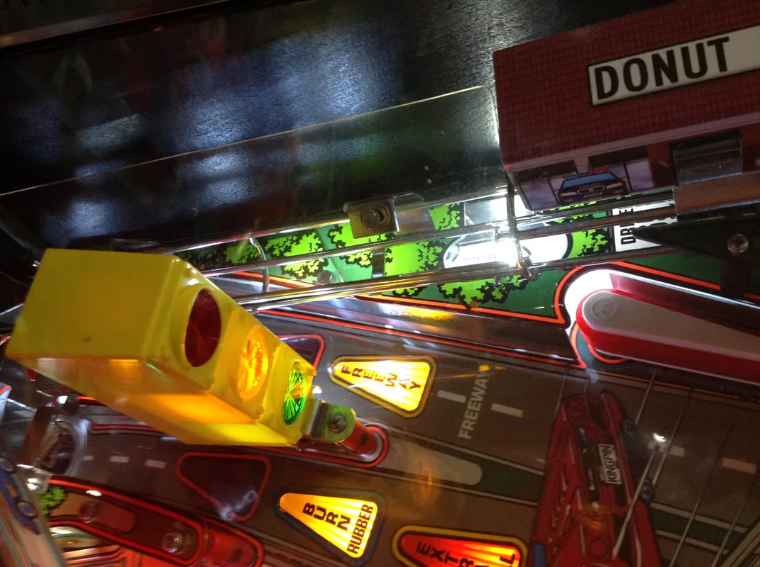
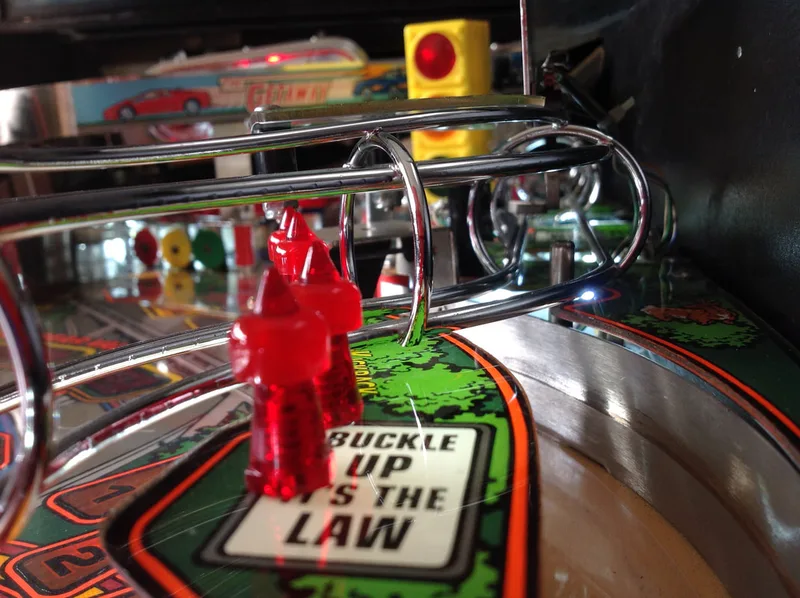
Raised freeway insert.

Luckily, I found two of the ball guides for sale by two retailers in the US. I grabbed these while Fiona was visiting family in the US and she brought them back in her luggage. Saved a bunch on postage! However, I was still missing one ball guide for the right freeway orbit. I found a few miscellaneous ball guides in a bunch of used parts I ordered from Pinball Spare Parts Australia, including one that was approximately the right size. It was a tiny bit too short, but with a little bending with pliers, it inserted into the holes on the playfield just fine.
If you find that ball guides are being pushed out of their mounting holes, use a dab of glue on the ends of the guides as you insert them into the playfield. Often, the wood is damaged when the guides are removed from the playfield, so the glue helps secure them in place.

Left freeway orbit ball guide.
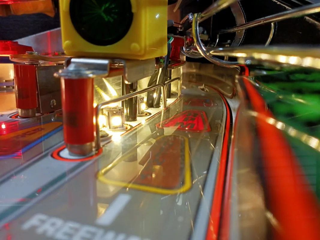
Right freeway orbit ball guides.
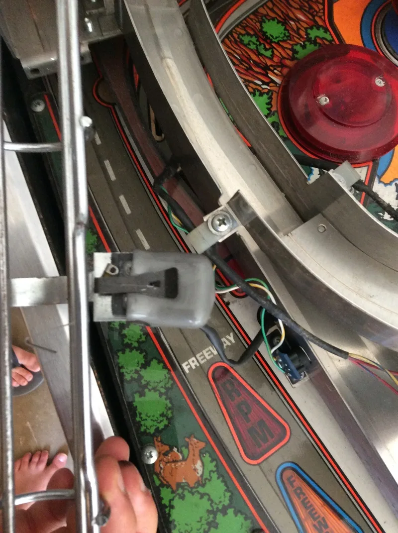
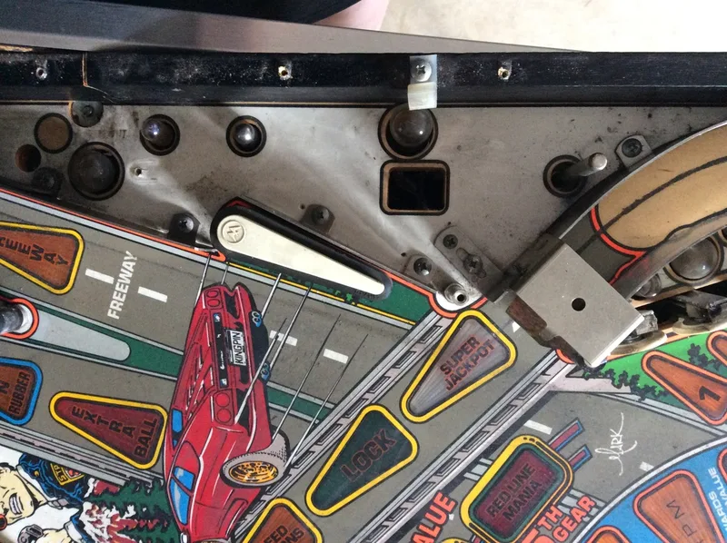
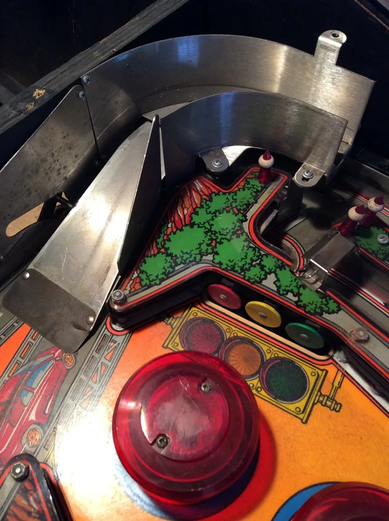
The only other thing in that area is a small screw that holds the metal ball guide to the back panel. I removed it completely and the hangups stopped. Turns out, the ball was going airborne after it came around this loop, bringing it into the path of the screw head.
The screw that was interfering with ball travel at the top of the left freeway orbit.

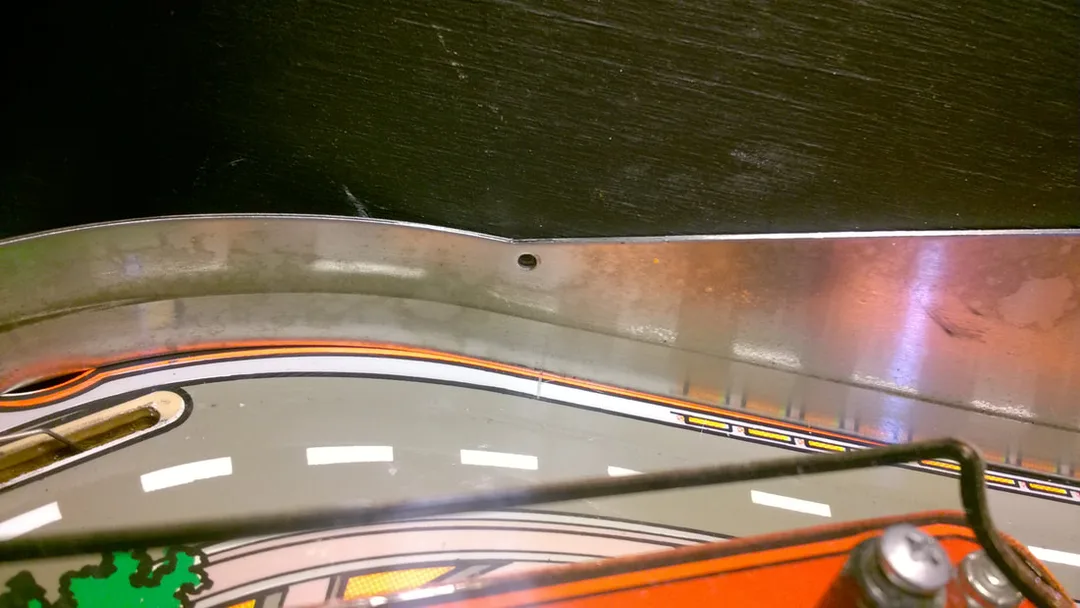
Funnily enough, I then had this exact same issue in the right freeway orbit. Balls coming from the left orbit at speed were getting launched into the air, hitting another screw that fastened the ball guide to the cabinet, and coming to a halt. This screw was in a position amenable to filming so I brought out the trusty slow motion camera again to see exactly what was happening. Like before, removing the screw fixed the issue.

The problem screw (half removed) on the right freeway orbit.
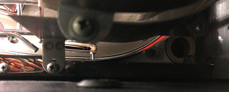
Thankfully, a friend of mine was able to fashion a new switch wire and attach it to the switch. Then it simply needed to be bent into shape and installed. It worked great! Thanks Daz!

Actuator wire replacement for the freeway orbit switch.
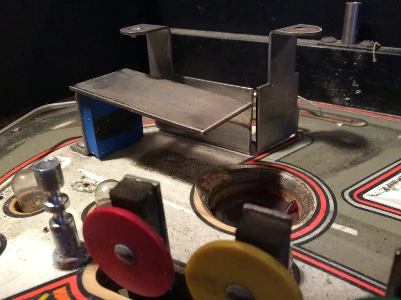
The up/down ramp causes a lot of issues on many Getaway machines. A search on Google shows heaps of forum topics asking for help with it. I found a great video on Youtube that explains how the up/down ramp works and the components in the ramp assemblies; well worth a watch if you haven't worked on this assembly before.
The important thing to note about this assembly is that the lift crank assembly (part no. A-12577) that lifts and lowers the ramp is held in place by a lift crank lock armature (part no. 01-8390) which "grabs" the lever underneath the playfield when the ramp is raised. The issue on my machine was that the crank assembly was raising the ramp, but then falling back down slightly before coming to rest. Balls would snag the ramp whenever they passed underneath, so I had to raise the ramp a tiny bit. I tried adjusting the bar that holds the ramp, wedging rubber or tape under the ramp to give it some lift, and rebuilding the coil assembly underneath the playfield, but nothing seemed to give the ramp the extra bit of lift it needed.
I determined that there was just too much slop between the lift crank assembly and the crank lock. I had to reduce this gap somehow. I resorted to sticking some plastic to the crank lock, effectively thickening it. The lift crank would therefore stop a little earlier, holding the ramp slightly higher. This adjustment worked for a little while, but I found that the piece of plastic would keep coming off. So my good friend Daz made up a new crank lock part, making it thicker. This worked well, and now the ball flies under the ramp with no contact at all. For such an important assembly, I was surprised there was so much slop in its movement. I wouldn't be surprised if a lot of Getaways actually have this issue, but it goes unnoticed.
Newly fabricated crank lock with a thicker catch section.
New crank lock installed, grabbing the lift crank assembly.
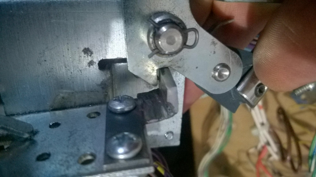
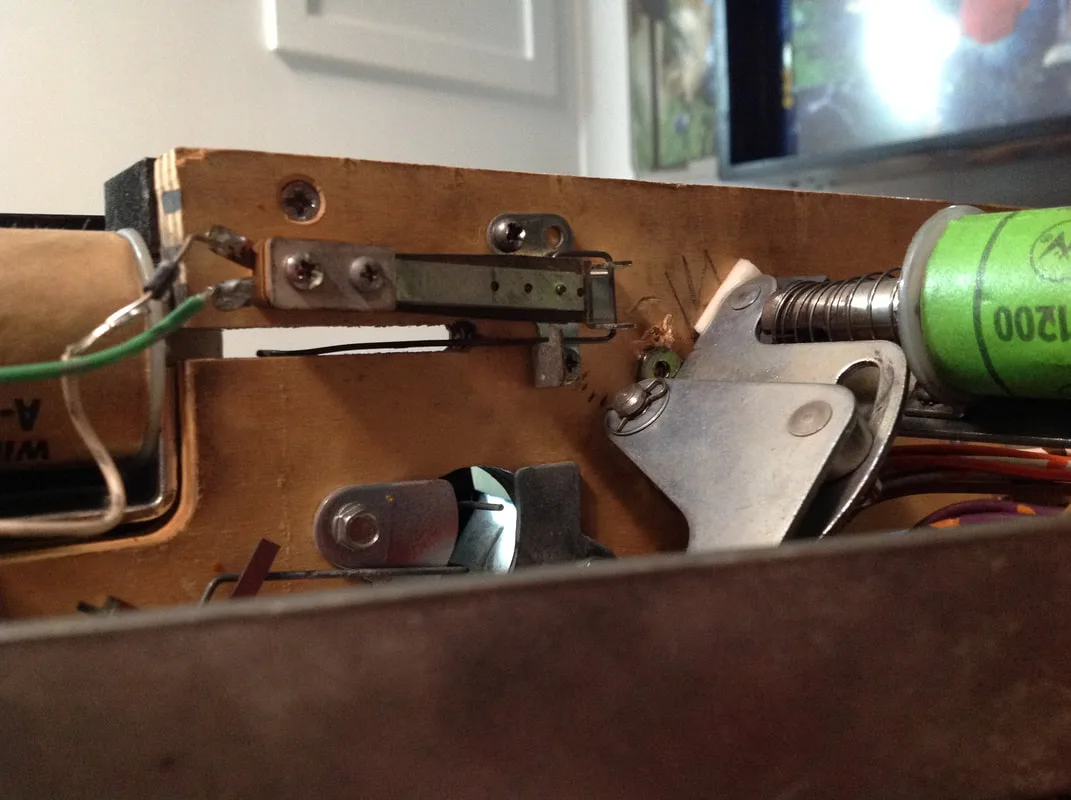
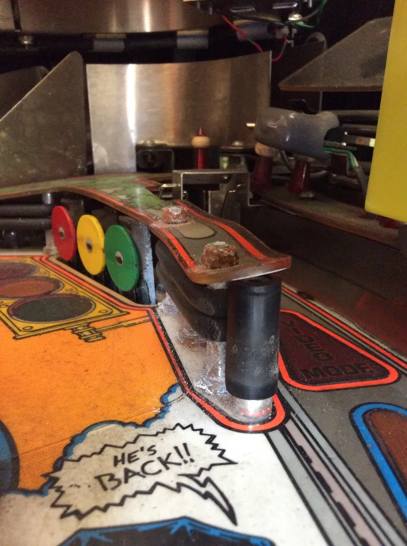
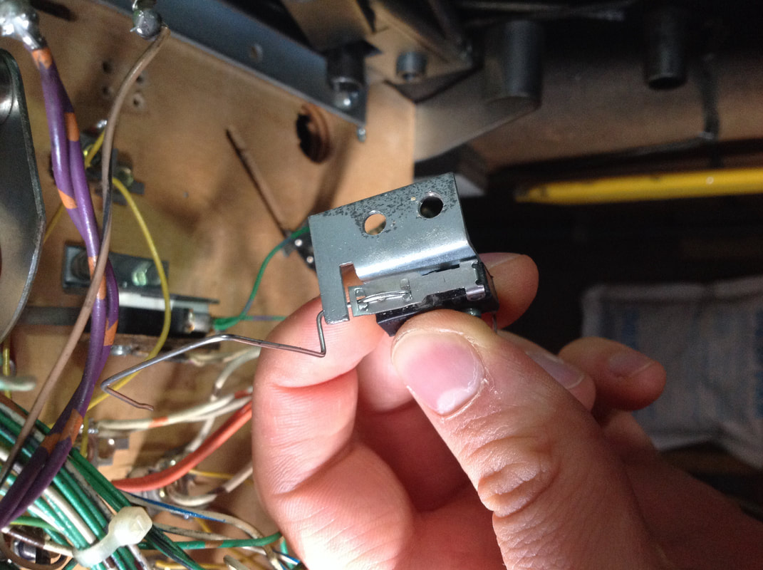
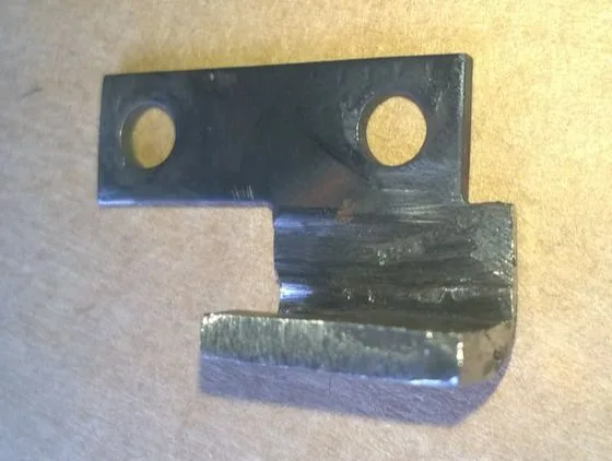
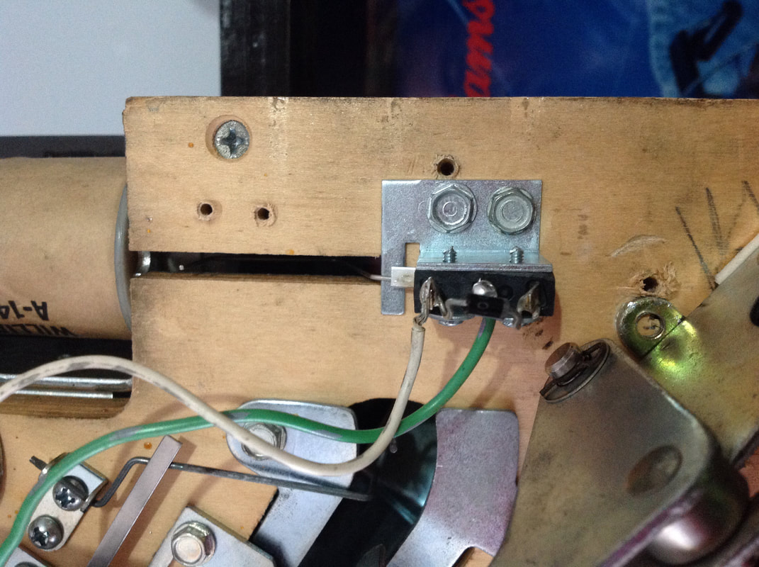
Older style leaf switch used for the shooter lane switch.

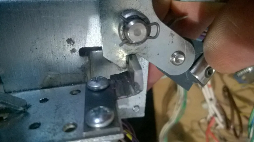
Correct microswitch and bracket assembly used as a replacement.
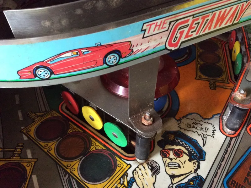
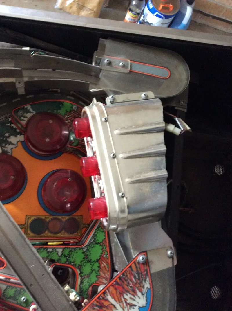
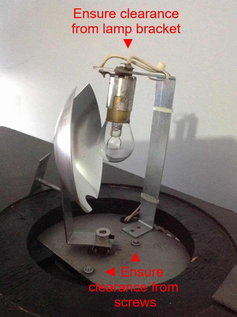
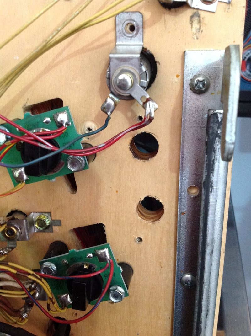
When I took the dome off to have a look at what happened, I saw that the reflector assembly was hitting the motor plate and lamp assembly as it had been fastened too low on the motor shaft. So I loosened the grub screw and raised it slightly. But be careful - if you secure the reflector too high on the motor shaft, it will hit the lamp support at the top, too! So install the reflector and move it manually through its full range of motion before tightening the grub screw. You might just save your beacon motor! If you do ever destroy the beacon motor, replacements are available (Marco).
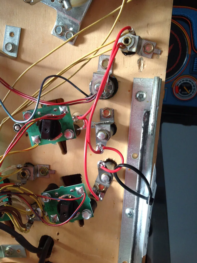
Unnecessary screw adjacent the ball trough eject assembly.


Unnecessary screws removed.

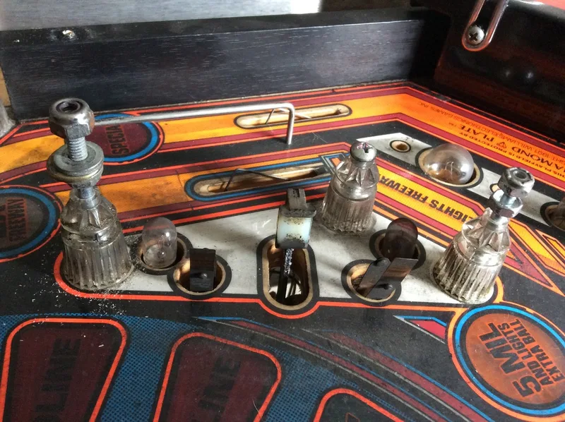
Original playfield with two empty holes with dimples for screws.
New lamp sockets installed and connected to GI string.

The wiring was a little fiddly as I was daisy chaining both sockets from a socket above, past a flasher socket. I had to cut one of the socket brackets down slightly so it would fit next to the flasher socket without shorting against it. Then it was just a matter of soldering leads to the sockets themselves and the socket tabs. Unfortunately, I did not clean the surfaces of the sockets well enough and the solder didn't grab onto one of the socket bodies. So I soldered the leads to an old alligator clip instead and clipped that to the socket bracket. This setup works well and lights the area above the upper flipper nicely. Definitely not the most significant improvement I've made to the game, but a good way to use otherwise empty playfield holes!
Area now lit with the two new lamps.

After reinstalling the power driver board after checking it for issues, I reconnected everything and started a game. However, the plunger didn't work. I checked the usual suspects including transistors and fuses, but they were all good. So I dove into the manual to see where to go next. I checked for power at the coil lugs and got no reading. Definitely a wiring problem, then. So I started to check for continuity from the power driver board to the plunger.
According to the manual, the plunger is supplied power through J107-2 and the transistor is connected to the coil via J127-5. I had good continuity from J127, but none from J107. I checked all of the other coils connected to J107-2 and all of them were getting power and working normally. This is weird, because all of the coils are daisy-chained together and the plunger sits right in the middle of the group. So a non-working plunger coil should knock out others in the chain.
The wiring for the plunger coil has been a source of confusion for many and there are plenty of threads on Pinside that discuss it. The problem is that the solenoid wiring diagram in the manual is actually incorrect. The plunger is not supplied power by J107-2. Instead, 50 volts is supplied via J109-7; the only wire on that connector. It seems that this wiring change was done at the factory and went undocumented in the manual. References online to J109 made me go back and recheck my work. Sure enough, I had forgotten to plug J109 back into the power driver board as it had gotten stuck behind the board. This explained why the plunger did not have continuity to other coils in the same group; it is serviced by a different circuit entirely. The fact that the plunger was the only coil not working also indicated this. This was a stupid problem to have really, but it was good for forcing me to learn more about solenoid wiring in the game.
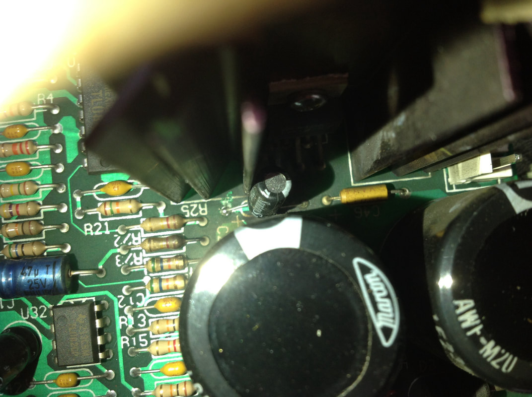
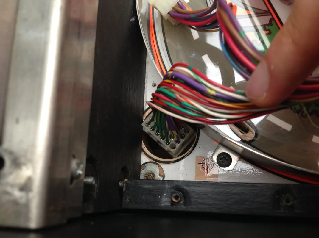
J109 power driver board connector stuck behind the board.

I noticed that the issue would come and go during the same game and that moving the machine slightly could make it come and go. So I suspected some kind of connectivity issue. Looking under the playfield, I couldn't see anything amiss, and started to probe around with the affected lamps and sockets. All of the lamps were working properly; they were just lighting up at the wrong time. While inspecting some lamps near the bottom of the playfield, I realised that moving the wiring loom would cause the issue to start and stop. I followed the wiring loom around and traced some of the controlled lamp wires to find the issue.
The wire for one return row of controlled lamps had been rubbing against the service rail under the playfield. The wire insulation had been worn through so that the bare conductors were in intermittent contact with the service rail. This was grounded, so whenever the wire touched it, the connected lamps would light. Neat, huh! Some electrical tape on the wire and the service rail in the location that they were rubbing put an end to the issue. I'll cut the wires and heatshrink them properly at some point.
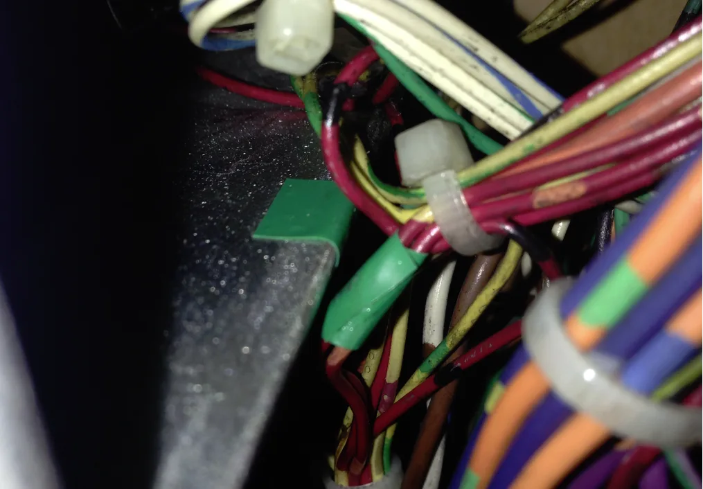
Damaged wires protected by tape as well as the service rail they were rubbing against.

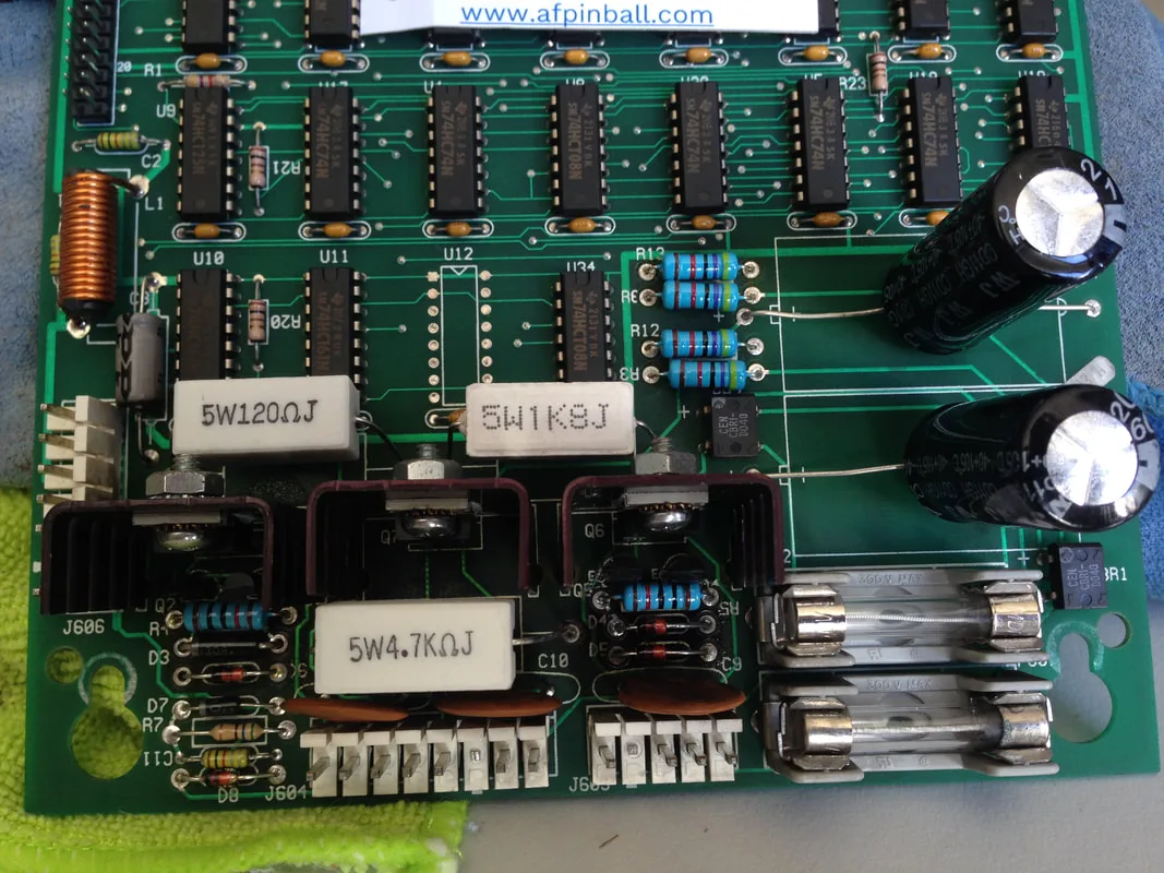
Display driver board high voltage section after rebuild.

Original burned J115 connector.
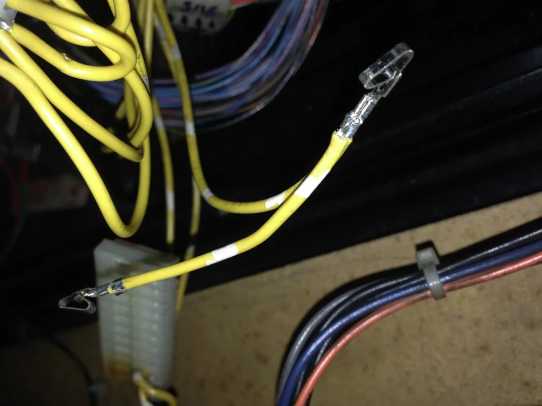
Recreating a "looped" wire using crimp terminals.
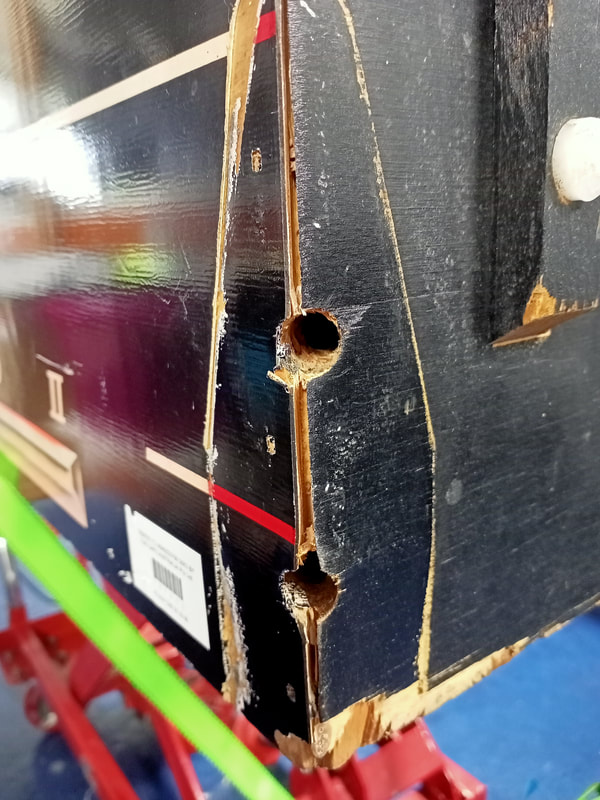
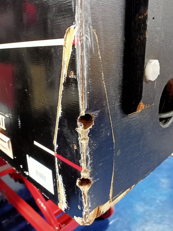
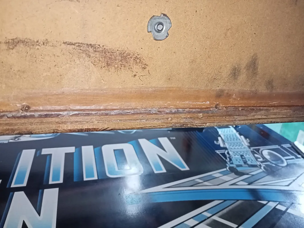
Splits in cabinet join, right side.
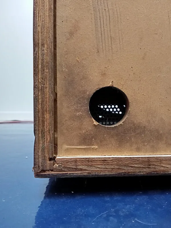
Splits in cabinet join, rear left.

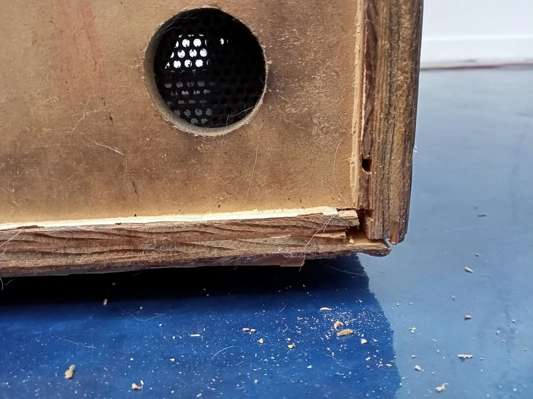
Splits in cabinet join, rear right.

These splits were simple enough to fix with some liberal application of Selley's Liquid Nails Heavy Duty. I like the heavy duty stuff as the cabinet needs to be strong to withstand the shoves and tilts it usually sustains during play. The stronger the adhesive, the better! Squeeze it as far as possible into the split joins and pack it in with a craft stick as tightly as you can. You want to clear out any bubbles and air gaps to ensure the bond is strong.
Then, some clamps around the cabinet to secure it in place as the glue sets. I use ratcheting straps (Bunnings) for this, as you can tighten them around the entire cabinet and clamp several joins at once. Leave the clamps in place for a day or two until the glue is set, and voila, all done!
Cabinet during clamping, left side.
Cabinet during clamping, bottom panel.

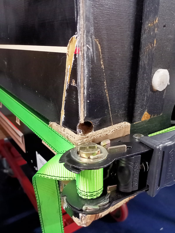
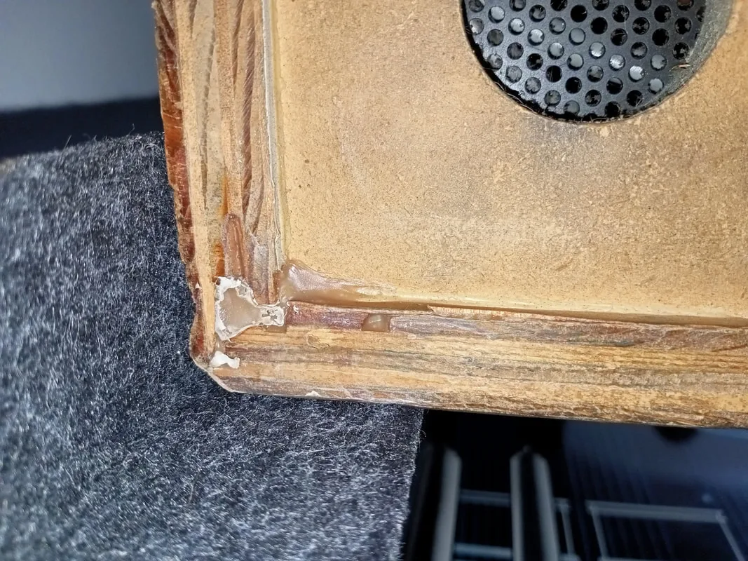
There was also some extra clamping to be done around the rear right corner, where the cabinet seam had split slightly where the leg mounts. This area got another squirt of adhesive and was again clamped for a day to set.

Split cabinet seam at the rear right leg.

Loaded with glue, clamped, and ready to cure.
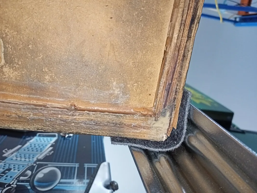
After curing; looks ugly but it is solid as a rock.
Once all of that adhesive was cured, the cabinet was back to full strength again. Ready to be used and abused for another few decades, hopefully!
Rear right corner after repair.
Front right corner after repair.

Right underside after repair.
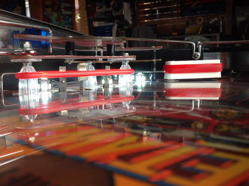
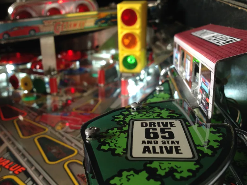
I originally installed yellow Cliffy post sleeves in the Getaway, but it didn't look quite right. I then installed a set of red sleeves, and these seem to fit the playfield colour scheme much better. This Getaway had two yellow (bottom) and one white (upper right) flipper bats when I purchased it. I replaced them all with new white bats and fitted them all with red Super-Bands. I went for white rubber rings which look quite nice, though I can understand why some people prefer the look of black rings on the Getaway. I also trialed some Super-Bands slingshot rubbers in red (PSPA). One thing I did notice about these rings is that they are super tight - ordering one size up from what is specified may be a good idea as the bands put a lot of pressure on the posts that support them. Other than that, they look good, and on the slingshots there isn't a noticeable change in bounce.
LEDs were installed throughout the machine. For feature lamps, I colour matched all of the inserts. For the LEDs under the playfield, I used quad-LEDs from Luke's Pinballs, which have four individual diodes (instead of the single diode types I normally use). I figured a little extra brightness would look better. However, the quad-LEDs are exceedingly bright, and I'd recommend sticking to single-LED lamps (at least for the inserts). However, some people like their playfields to be bright, so to each their own!
The general illumination was replaced with white 5+1 LEDs, with frosted white LEDs in the backbox. The Supercharger and Red Line Mania lamps on the supercharger ramp entry were replaced with yellow and red frosted LEDs, respectively.
I made up a spreadsheet to make ordering and organising the LEDs simpler. Feel free to download it and use it!
Installing the playfield protector.
Playfield protector installed. Shiny!
Finally, I downloaded some fantastic custom instruction and pricing cards. There are heaps available for The Getaway. I use two sets; one from Pinball Boy and another form Pinball Cards. If you download a set, consider donating!

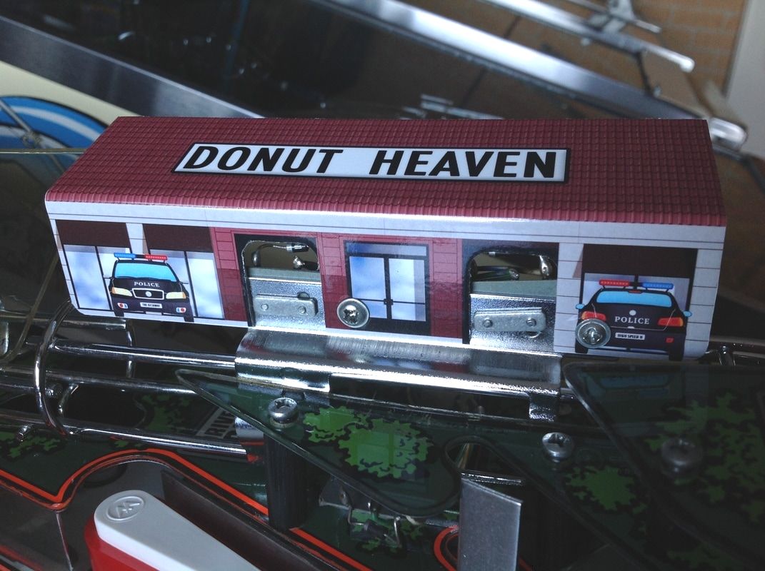
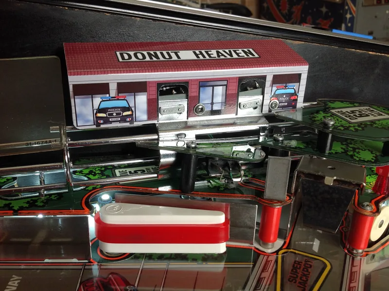
Getaway is a game that there are heaps of mods available for, particularly decals. One which I decided to get was the donut shop decal for the ball lock area. Thanks to Wade at Aussie Arcade for the decal! This is a cheaper mod than ordering the 'real' 3D donut shop (by Mezel Mods) and is simpler to install. I like it!

Donut Shop decal covering the lock area.
Conclusion
The Getaway is a personal favourite machine of mine and I can't see it ever leaving the collection. It is a super fast game with an awesome theme. The supercharger never gets old. While the gameplay isn't as deep as other machines, getting super jackpots consistently can still be tough. In my opinion, the Getaway is great for long jackpot-chasing sessions or short, casual games alike.
What we learned during our Demolition Man restoration definitely came in handy during our Getaway restoration. Knowing what type of posts usually went where, and what components to expect in certain places made reassembly much easier, even when we forgot to take some specific photographs. Just goes to show - the more you practice, the easier it gets!
Im currently doing a HS2 restoration and your pictures and journey help greatly
looks great well done
Glad you found the information useful!
Alex
Thanks for the feedback! I'm sure the shop will do an awesome job on the restoration. Have fun playing it!
The red/gray wire should be in position 9 (far left).
Hope that helps!
Thanks so much.
I'll try and send some photos through tomorrow. As for the kickstand, my advice is not to use it. It warps the playfield, and doesn't mate with the playfield very securely. One slip could be dangerous. Simply lift the playfield up and rest it against the backbox if you need to access the underside.
Alex