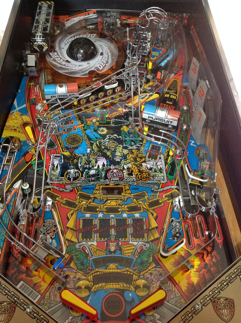
 Time to lay down the law! Judge Dredd was the last Bally/Williams machine I had left to restore of my original road trip haul. I had left it to last mainly because the look of all the ramps criss-crossing the playfield, the idea of having to fiddle with the Deadworld, and the sheer size and weight of the damn thing all told me that this would be a painful restoration. Just looking at it and comparing it to Demolition Man (Williams, 1994), my only other widebody game, the Judge Dredd playfield was packed with more features and more mechanisms, which meant more to clean and more to service. But, as always, I was up for the challenge! Initial condition report (click on sections below to view details) Cabinet
Average condition overall.
Above playfield
Good condition overall.
Under playfield
Average condition overall.
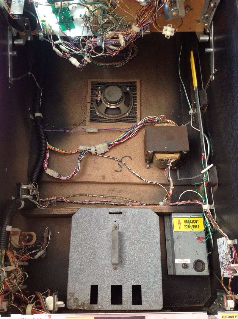
Electrical
Average condition overall.
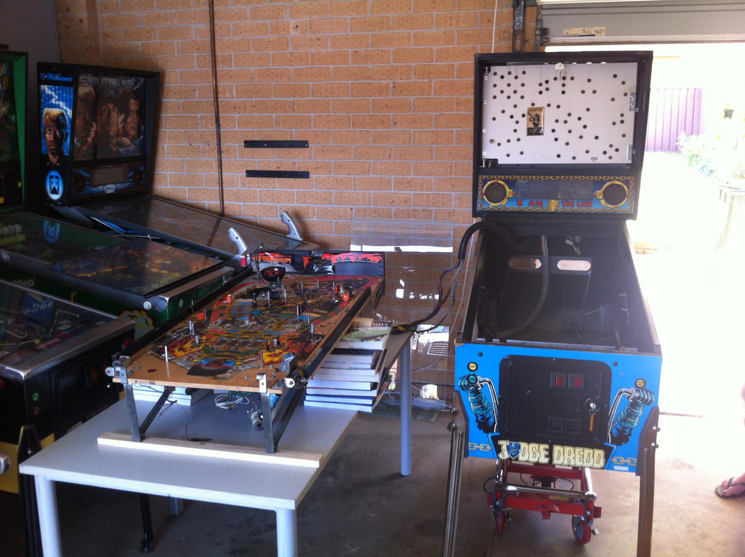
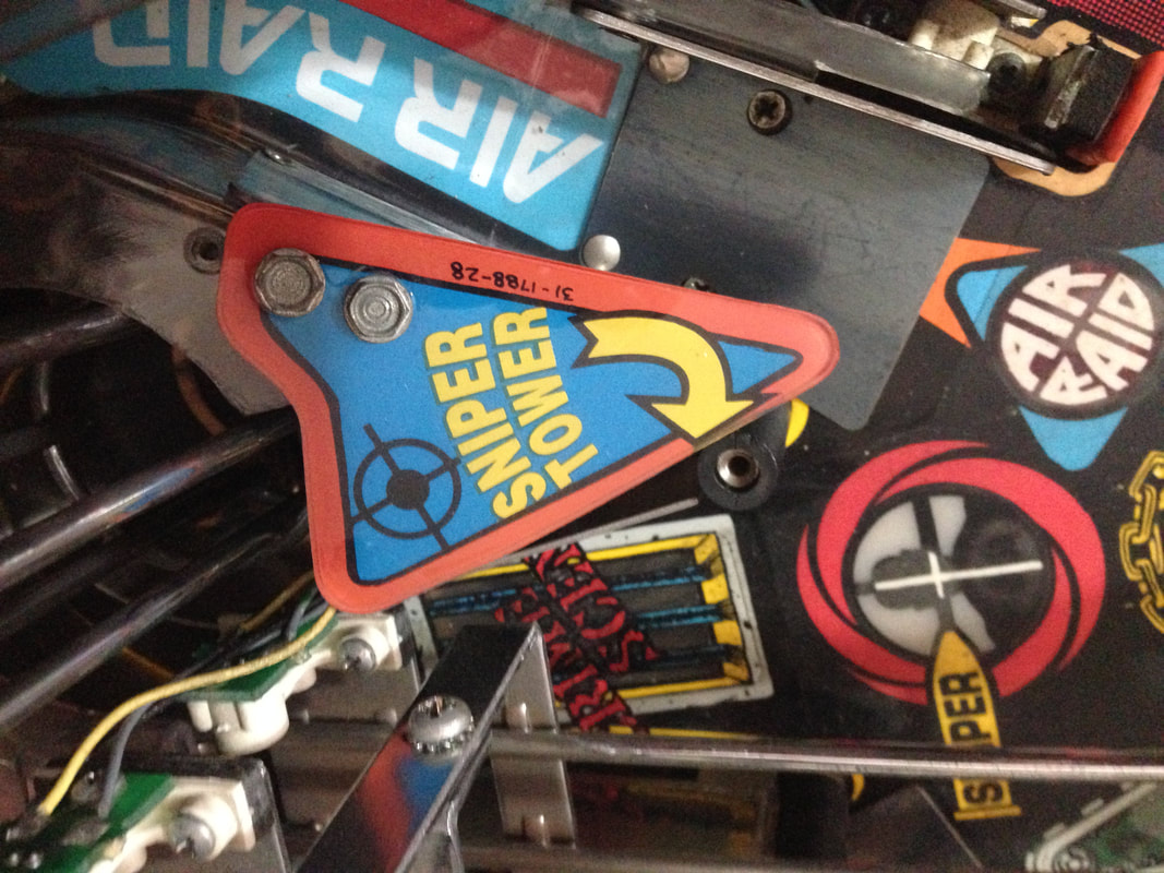
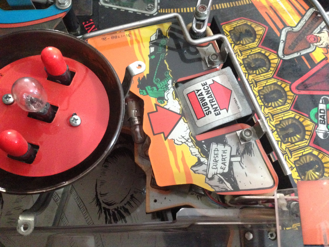
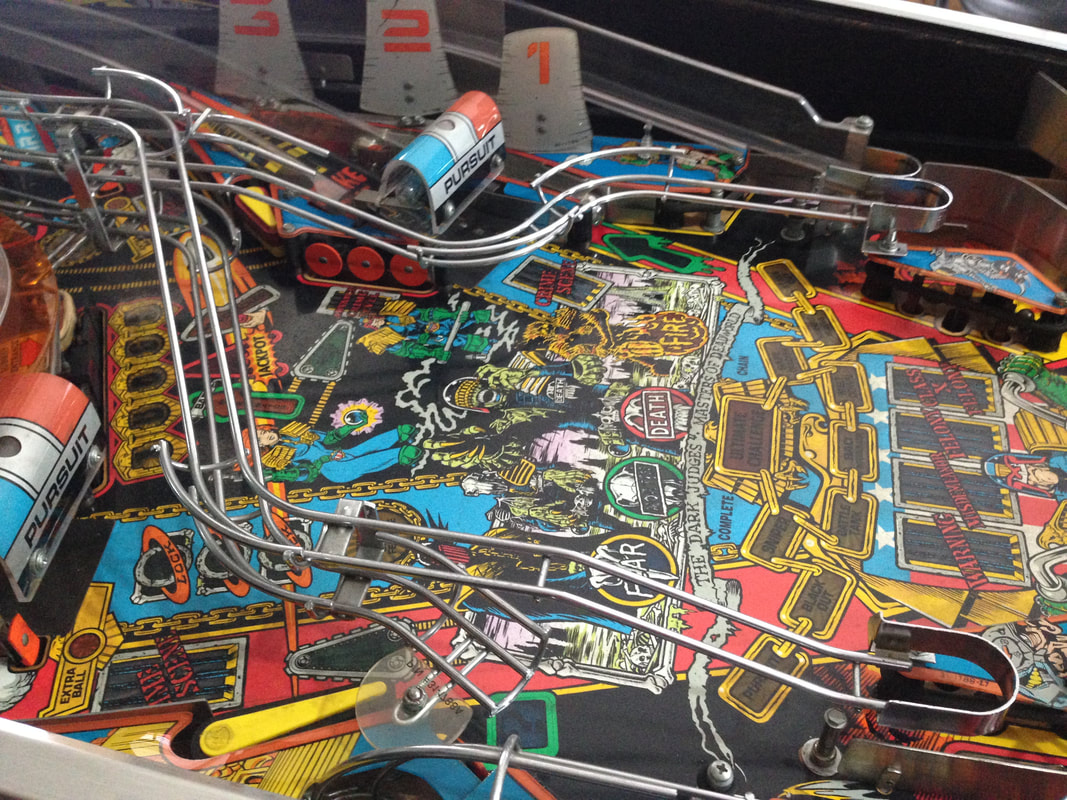
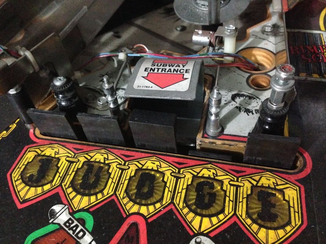
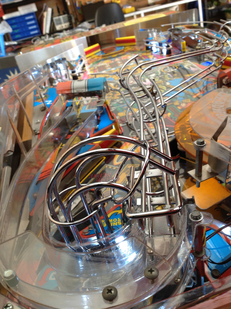
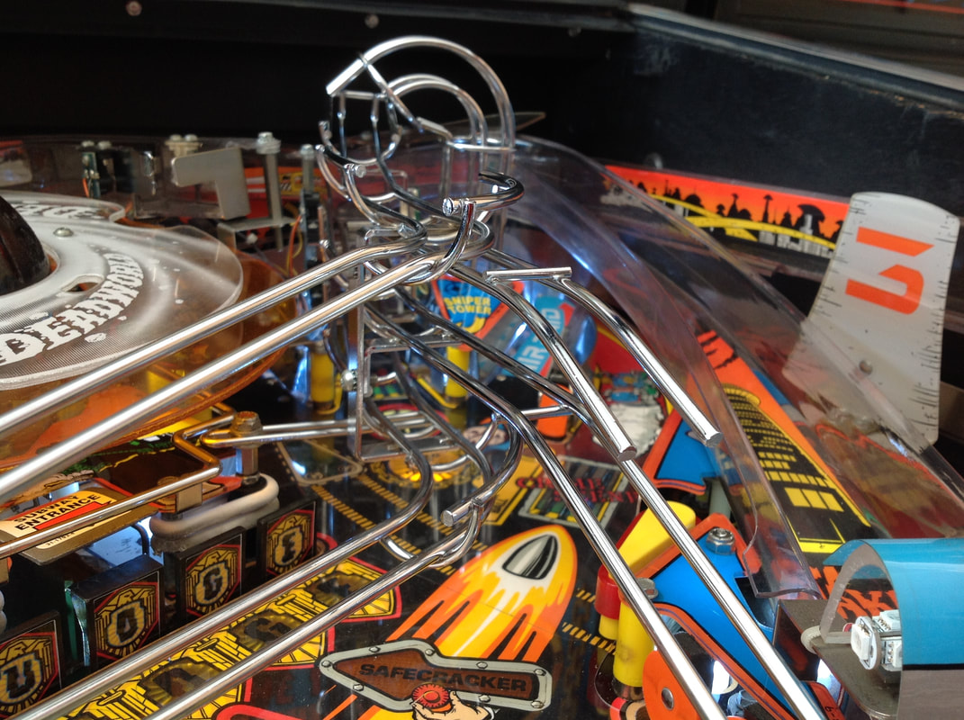
One thing I do remember about this machine was when we were first looking at all of the machines we bought during our road trip, Fiona and I both decided that Judge Dredd was probably in the best condition and played the best when we inspected it. We decided that if we couldn't get multiple machines for the price we wanted, then we could at least bring home Judge Dredd on its own. We thought, at the time, that there would not be much work in it. How wrong we were! Disassembly Judge Dredd has a lot going on on top of the playfield, so be sure to take more photos than normal when disassembling everything. The wireform ramps can be removed in one single piece. A very useful guide to refer to during disassembly is Adrian Cook's Judge Dredd shop-out guide. Take particular care on the underside of the playfield near the subway ramp. Things are packed in tight around this ramp, such as the lamp board and playfield wiring, so I found it easier to take most surrounding components off as well. After disassembly, the game went through my standard restoration process to get it playing and looking like new. During the restoration process, I dealt with a number of issues, described below. Tips & Troubleshooting (click on sections below to view details) Topper in pieces and missing bracket
The topper for Judge Dredd just looks way cool. That is probably why a lot of them are missing or damaged - they must have been irresistible to kids that wanted to steal them for their own bedroom walls. If you've ever tried to pry a topper off a backbox, you'll have found that it's not that easy. They're held down pretty tightly and you're more likely to break something that steal anything.
And that, I think, is what happened to this topper. When we retrieved it from the top of a storage shelf in the seller's warehouse, it was in two pieces. Not only that, but it was easy to tell that it was previously in many more than two pieces. Multiple sections had been glued back together and some small chips of plastic were missing here and there. The underside of the eagle's beak was completely missing so you could see through the topper. Even the bracket mounting holes at the rear of the topper had been broken and glued back together. Gotta give points for trying, though. It was actually glued back together quite well. But for the time being we just had to worry about putting together the two individual halves of the topper we had. We used Revell Contacta Professional glue to glue the pieces back together and it worked very well. The bond was strong and rigid. Unfortunately the piece for the eagle's beak was long gone, so we had to make do with a gap in the topper. No biggie. 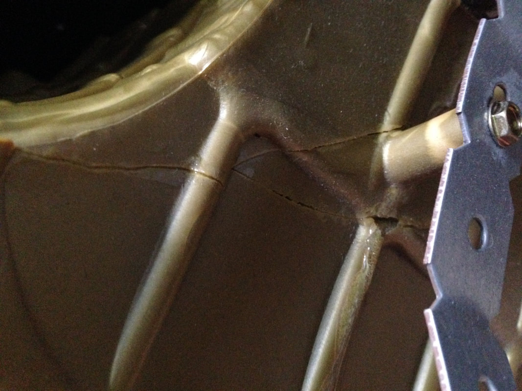
Close-up of the largest crack in the topper after gluing. Nice and snug.
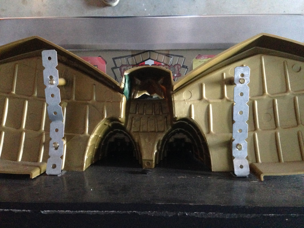
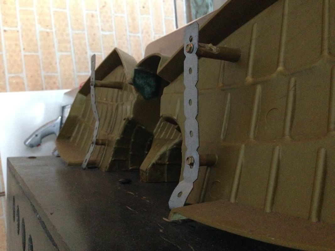
Replacements for the eagle topper (part no. 03-8936) are actually readily obtainable from several local suppliers (RTBB, PSPA, Mr Pinball). It comes in several varieties including the original mustard colour and reflective gold. I'm normally a sucker for original parts, but the gold eagle looks awesome and I would totally buy it instead of the original one. The next task was to mount the topper on the backbox. Unfortunately, the original bracket (part no. 01-11964) was missing, and at the time, it was actually quite difficult to get a hold of unless you could fabricate your own out of sheet metal. If I had to do it again now, I wouldn't bother, as the brackets are available from a local supplier (RTBB) and are a much better solution than my clumsy bracketing jig. But building clumsy bracketing jigs is half of the fun, isn't it? The mounting holes for the bracket, as well as the carriage bolts and nuts, were still on the machine. So all I needed was some material that I could secure to the original mounting positions as well as the screw holes on the rear of the topper. I had a look at what Bunnings had to offer and found something that worked quite well: Carinya Make-a-Brackets. These are sheets you can buy in multiple shapes and sizes which are notched to make them easy to cut down and fold into the shapes you need. I grabbed a 20 x 600 x 1 mm length (plenty for both sides of the topper) and cut it down to an appropriate size. Simply measure the distance between topper mounting holes, and cut the bracket to suit. The screws can go straight through the pre-drilled holes in the bracket. The back of this topper was not quite vertical and was on a slight angle for some reason, so I had to bend the bottom half of the bracket forwards to meet the screw hole properly. Next, I bent the bracket approximately 90 degrees so it would sit flat on the topper and I could line it up with the carriage bolt mounting holes. You will need to enlarge the mounting holes on the bracket as they are not big enough to take the carriage bolts. But once you've done that, they'll slot right in. I misaligned the holes in the bracket, and ended up having to cut new holes in the bracket instead. But once that was done, everything screwed in properly and stayed night and tight.
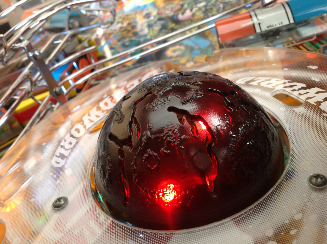
Deadworld rebuild
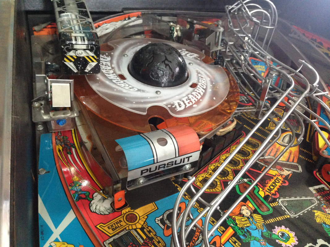
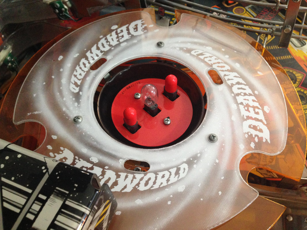
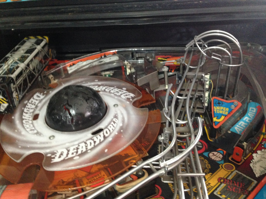
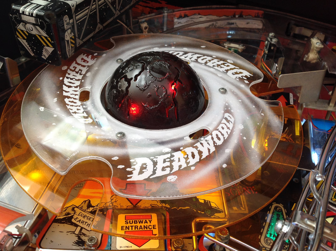
Deadworld before the commencement of work.
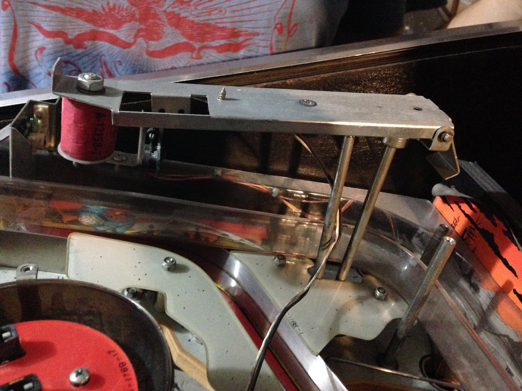
I consider myself to be very familiar with pain-in-the-ass playfield assemblies. I had certainly gained some experience in this area after having rebuilt the Doctor Who (Bally, 1992) mini playfield (once and twice!), and the Johnny Mnemonic (Williams, 1995) Cyberglove assembly. Those experiences prepared me well for taking the Deadworld apart and refurbishing it. It actually functioned somewhat normally to begin with, which was a good start, but its movement was slow and the crane did not pick up and drop balls consistently. Either way, it needed a rebuild. Before you dig into the Deadworld, it's a good idea to read a couple (out of the thousands) of threads on Pinside describing the variety of issues people have with the Deadworld. It's good preparation for things you may run into later on. I found it easiest to remove the entire Deadworld and crane/lifter assembly and clean it up on the bench before reinstalling it into the game. There are a fair few resources which are helpful to consult when working on the Deadworld, including this Pinside thread, Martin's guide to tuning the crane, First is disassembly. The entire assembly can be removed from the playfield but there are a number of parts that need to be removed first, both on the top and underneath the playfield. On top of the playfield, you'll need to remove the Deadworld rings. The upper ring (part no. 31-1801) and lower ring (part no. 03-8867) are screwed onto the main Deadworld shaft with three screws. Unscrew these and lift both rings off the assembly. 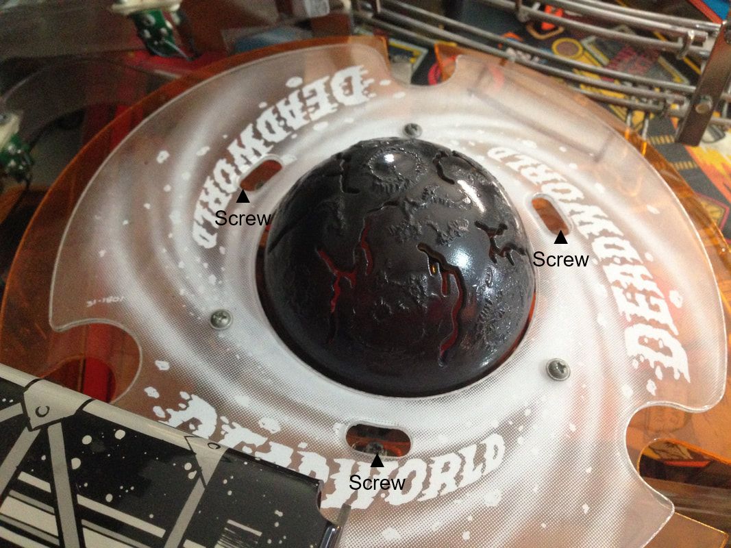
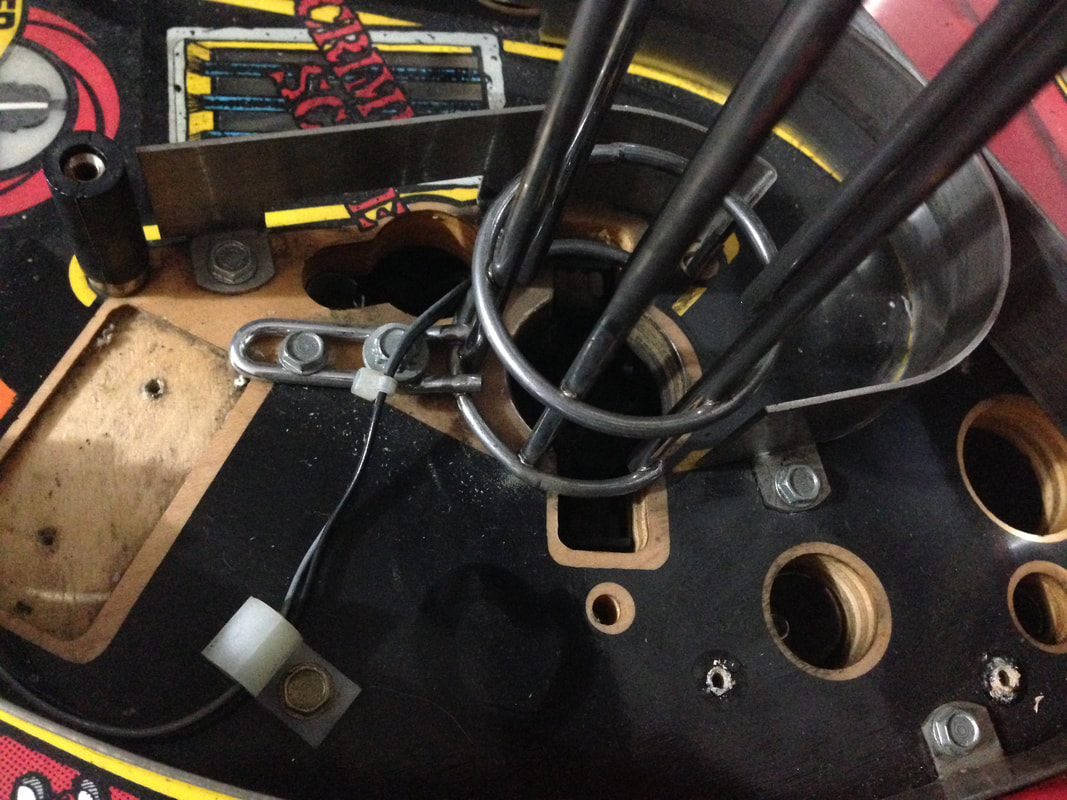
Screws for removal of the Deadworld rings.
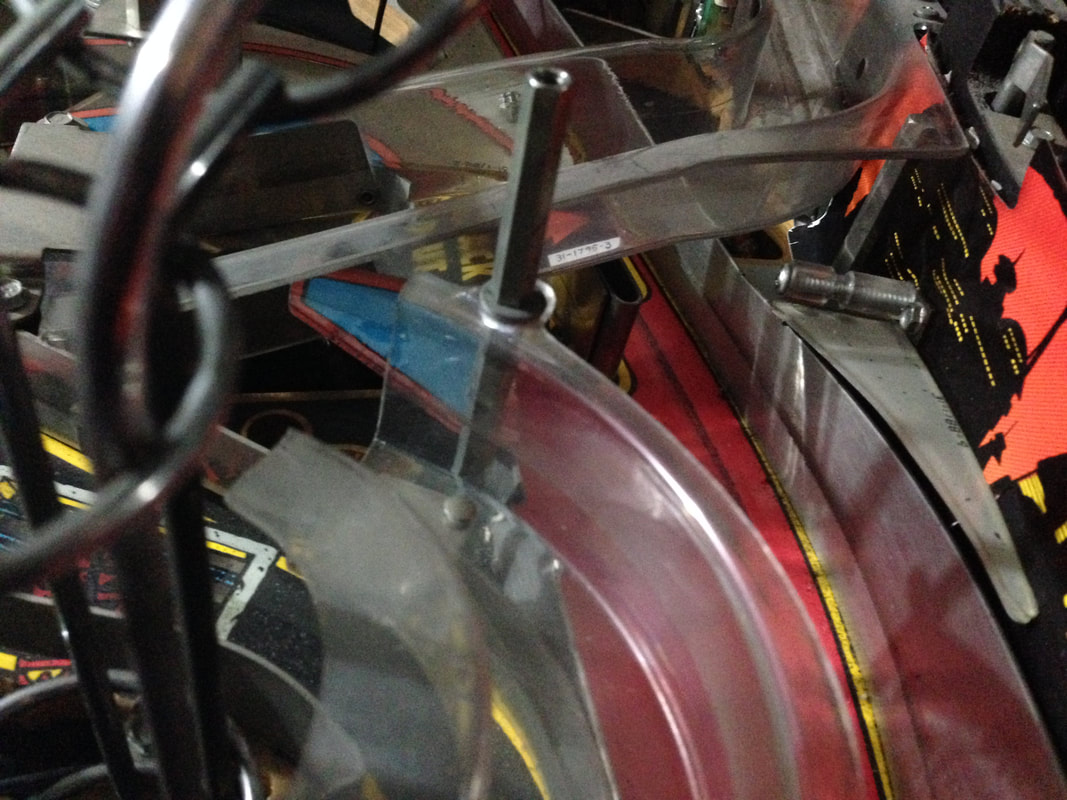
Next, you'll need to undo the crane arm lifter (part no. A-16769) by loosening the set screw at the rear of the crane, which screws into a pivot and hub assembly (part no. A-16788). Once this is loose, the crane can be lifted off the shaft. Secure it somewhere on the playfield so it doesn't fall down when you lift the playfield. 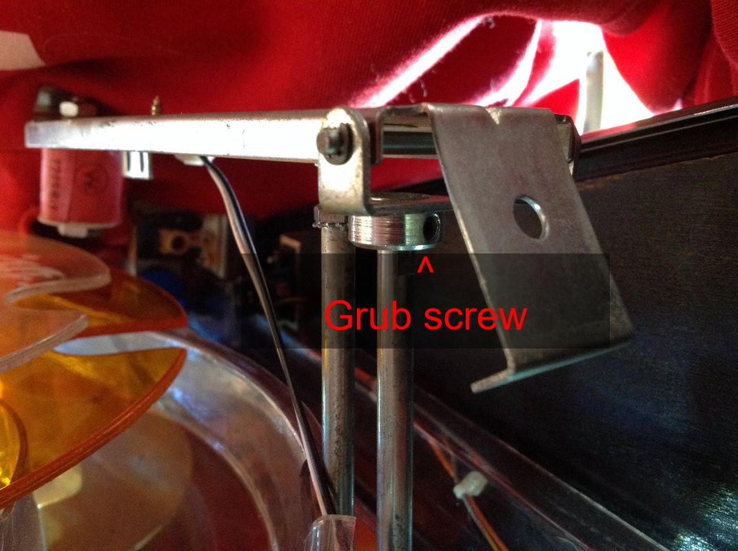
Location of the grub screw on the lifter assembly.
Under the playfield, you'll need to remove the lifter assembly (part no. A-17247). This screws into the playfield and the mounting bracket for the Deadworld motor. Once these screws are removed, you can pull the arm lifter assembly through the bottom of the playfield and remove it from the game. Don't forget to disconnect the lifter motor and the opto switch connectors, too. 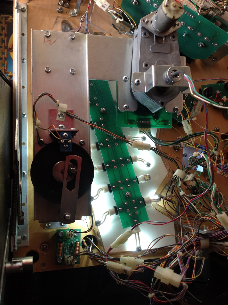
Screws and connectors for removal of the lifter assembly.
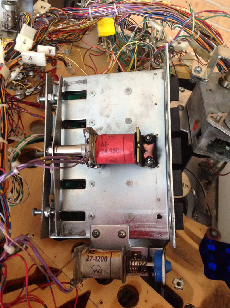
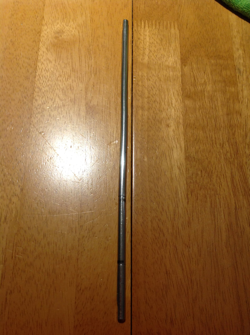
Now you can focus on the Deadworld planet assembly itself (part no. A-16478). Before removing the Deadworld, you will need to remove the plastic trough (two pieces) that sits under the Deadworld (part no. A-16947 and A-16968). I always thought this was a weird part of the playfield. The trough doesn't really serve any purpose. I think the only reason it was put in was to catch balls that might fall off the Deadworld ring, yet I've never seen this happen in a game. The trough is secured by wood screws and these are a pain to remove as the mounting bracket for the Deadworld is in the way. But you need to remove them first so you can pull the Deadworld planet through the playfield. Bit of a catch-22. Don't forget to disconnect the lamp board on the trough as well. Once the trough is off, the Deadworld can be removed. Unplug the Deadworld motor and the lamp connector. Then simply unscrew the wood screws holding the mounting bracket (part no. A-16808) in place. Hold the assembly while you do this, as it is heavy. Now pull the entire assembly through the playfield, being careful not to damage the planet as you pull it through. And that's it! Now you've got one Deadworld assembly, ready to refurbish. At this point, take plenty of photos of the entire assembly from different angles so you'll have plenty to refer to when you put it back together. One issue with the arm lifter assembly was that the lifter shaft (part no. 02-4818) was seriously bent. This was probably from somebody pushing the playfield back into the cabinet while the crane was still poking out of the left side of the cabinet. The kink made it a lot harder for the arm to move properly, making it difficult to pick up the ball from the Deadword ring. This was easily fixed with a hammer and anvil, hammering the shaft until it was straight.
The Deadworld planet plastic (part no. 03-8858) is made up of a top and bottom half. The halves are meant to screw together, but the threads on my planet were pretty much gone and it didn't take long for the planet to work itself loose; even a light touch would knock it off. So I taped it down around the rear of the planet, locking it in place. It's important to make sure the planet is secure as if it falls forwards, it can jam the Deadworld assembly. Disassembly of the gearbox is pretty straightforward. The main issue is the pair of wires that thread through the main shaft from the connector underneath the playfield to the lamp board on top of the Deadworld. These wires made it impossible to fully disassemble everything. So, I removed the terminal pins from the connector and slid the wires out of the shaft. Remember to mark which pins go into which connector slot! 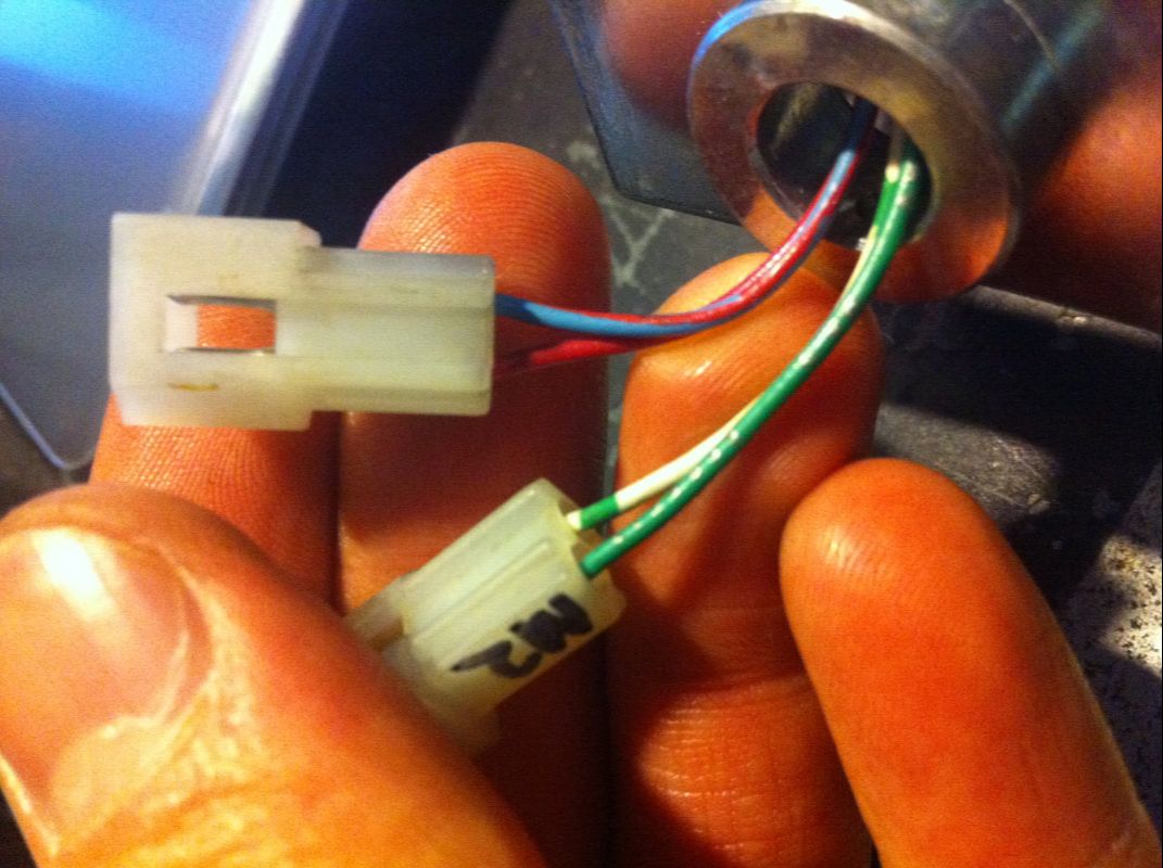
Connector wiring for wires threaded through the Deadworld shaft.
I found that there was a bit more crud inside the Deadworld gearbox than I'd normally expect, but this was probably because it is an open-ended gearbox which allows dust and debris to get in. Regardless, it needed a full clean out. I removed all of the gears and cleaned them with a degreaser, as well as the gearbox casing. I applied some Nulon Extreme Performance Grease after clearing out the old gunky grease. Remember to also clean the smaller gears on top of the gearbox. The rest of the shaft and associated parts also got a good clean. After that, the gearbox was nice and clean and the gears spun without any issue, so it was time for reassembly. 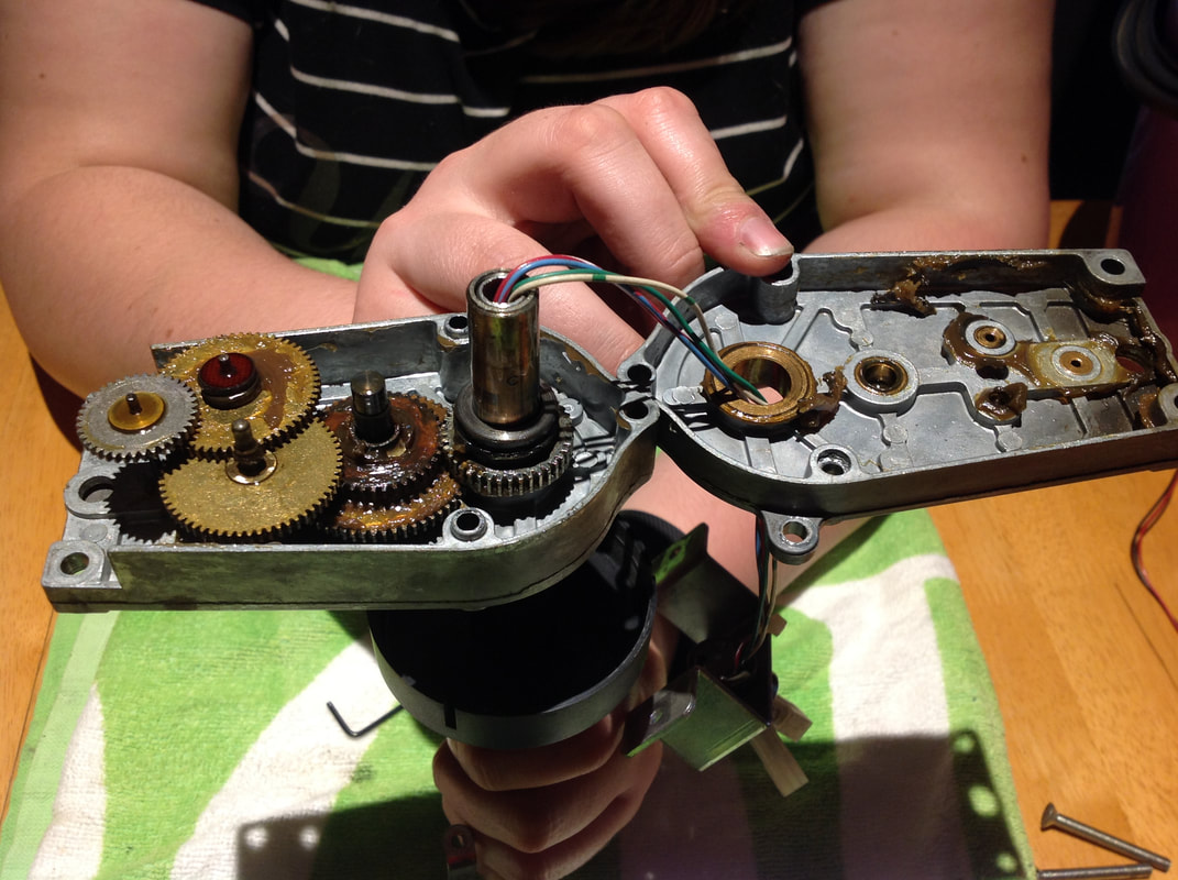
Deadworld gearbox assembly before cleaning.
Reassembly is pretty straight forward; just follow the disassembly in reverse, using photos for reference. One thing to be aware of is any protrusions caused by nuts or bolts that can get in the way of the assembly. My gearbox casing had been taken apart previously and put back together with screws and nuts. I initially installed these the wrong way around, which meant that the gearbox could not sit flush with mounting bracket. So, again, check your reference images carefully. 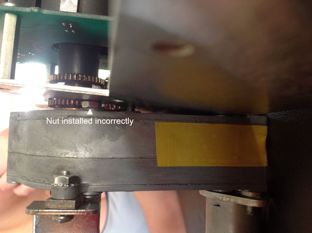
Rogue nut installed in the wrong location, causing the assembly to sit at an angle.
Also be careful when tightening the grub screw that secures the opto interrupter (part no. 03-8869) to the main shaft. I overtightened this screw and cracked the opto interrupter plastic, creating a hairline fracture down one side. You can get replacements for this plastic (PSPA), but I found replacing it was not necessary. The crack was hardly noticeable when the screw was loosened a bit and the plastic still did its job of blocking the optos properly. 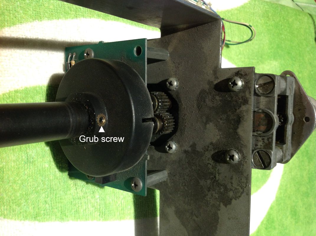
Beware of overtightening the grub screw on the opto interrupter (left of image).
After the first couple of hiccups above, the rest of the reassembly went pretty smoothly. I got everything back together, installed the assembly on the playfield, and tested it to make sure it worked. All good! Cue the first Deadworld nightmare. I was pretty happy with my restoration effort, so I organised a meet with some local pinheads to play my machines, have some drinks, and talk pinball. It was gonna be fun! All was going very well until halfway through the afternoon. At this point, somebody let me know that Dredd wasn't working properly. I had a look and saw that a ball was stuck on the Deadworld. For some reason, it wasn't getting delivered to the crane and the game had lost track of the ball. Looking into it, I found that the a fuse in the backbox had blown. It was fuse F105, which protects solenoids 1-8, including the globe motor. I thought nothing of it, removed the ball, placed it back in the trough, and then replaced the fuse. Must have been a one-time thing. The Deadworld spun and the game reset without issue, so I went away to continue the conversation that Dredd had interrupted. Unfortunately, the blown fuse was actually an indicator that something else was wrong and I didn't notice it until it was too late. The next time someone pointed out that Dredd wasn't working, it was having the same issue. The ball was stuck on the Deadworld, and it wasn't spinning. The fuse was intact this time, and everything else seemed perfectly fine with the game, except for the fact that the Deadworld would not spin. Occasionally it would jolt a little and hesitate, but only for a fraction of a second. I popped the hood to have a look and entered the globe test option in the test menu. The globe motor was running as was evidenced by the noise of the gearbox, but nothing was turning. Thinking something might have been stuck, I took a closer look inside the gearbox to see if anything was lodged in it. This is a situation where it is really handy that the gearbox is open-ended! Looking in, I could see the motor working, a few gear spinning, but the main shaft stayed stationery. It looked like there were gear problems after all - uh oh! I removed the assembly and took the gearbox apart (again!). It soon became clear what the issue was... one of the gears had been completely stripped of its teeth and was no longer engaging with the next gear in the chain. The gear was almost completely smooth around its circumference! 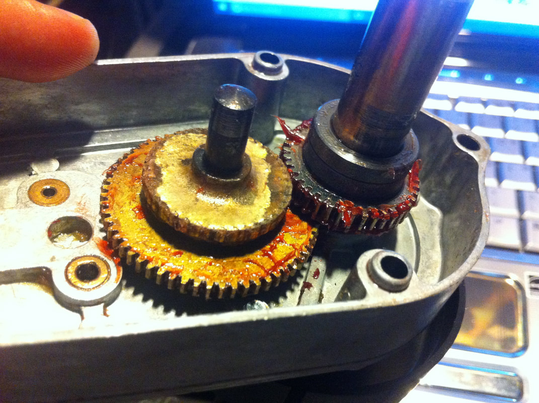
Stripped gear in the Deadworld motor gearbox.
When you research Judge Dredd gearbox problems, you find that the most common problem is that this gear becomes loose and begins to spin on the shaft. There are heaps of threads on Pinside about this issue. Unfortunately (or maybe fortunately), as it is a relatively common issue, there are a few solutions. Most people seem to resort to brazing the gear to the shaft or installing pins to keep it secure. Brand new gearboxes and motor assemblies are available (Marco), but this is overkill if only a single gear is broken. Steve Young (PB Resource) performs repairs on all Multi Products gearboxes and motors, so for a modest fee, you can have your gearbox professionally refurbished by him. However, shipping a gearbox to the US for repair is not really an option for us Aussies. I reached out to Steve and he was very helpful in finding a solution to my problem. Long story short, I was able to obtain a replacement gear (and shaft) to replace my broken one. The difference is pretty stark when they are put side-by-side! 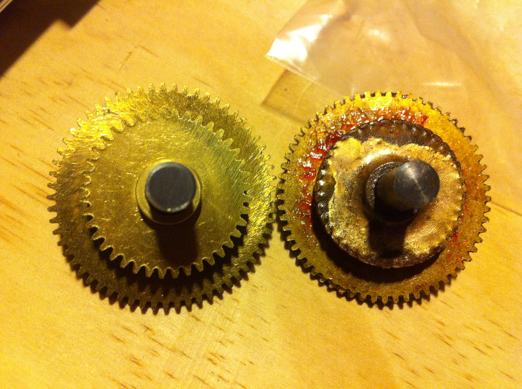
New shaft and gear next to the old, stripped one.
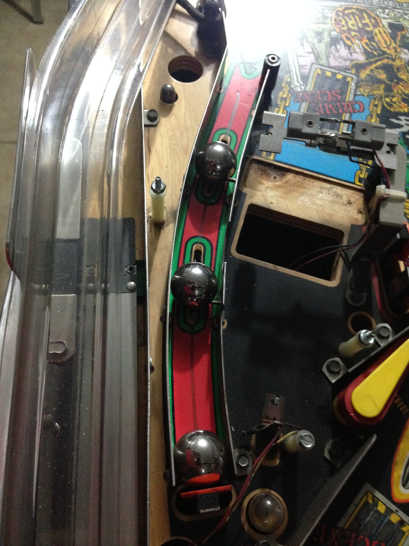
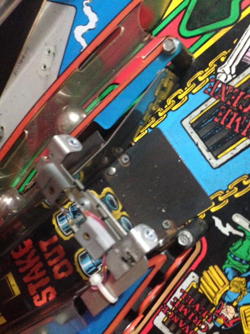
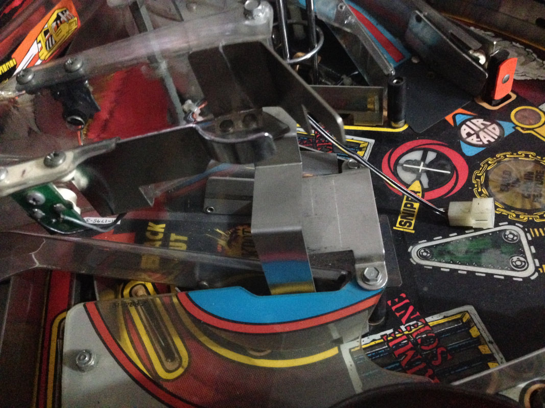
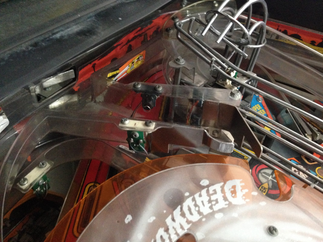
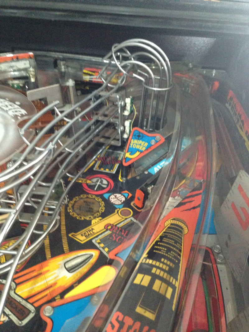
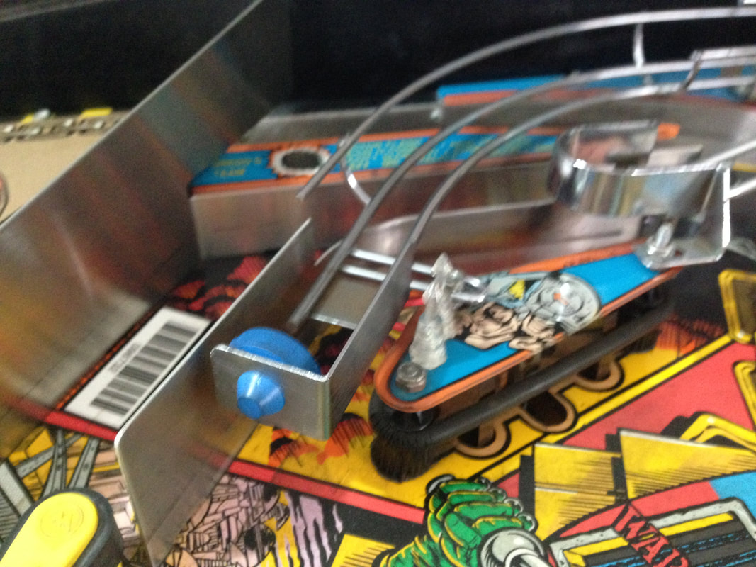
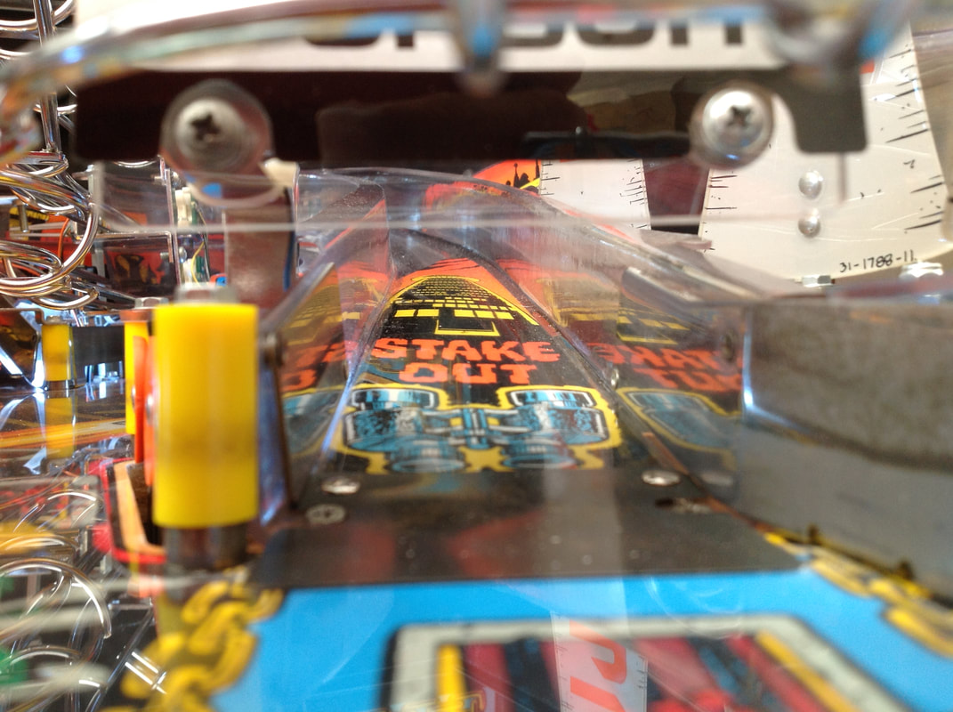
I dropped the new gear and shaft into the assembly and reassembled the whole thing. I then turned on the game and got ready to test the motor. The good news was that the motor was turning the Deadworld nicely. So the repair, at least, was a success. But then I ran into another problem. The Deadworld turned until one of the edges of the orange ring cutouts snagged on the left ramp. This halted the Deadworld and the gearbox started to make a horrible noise from straining to move. Luckily, I was watching everything happen, so I turned the machine off before it stripped another gear to shreds! I believe this was what happened in the first instance to destroy my original gear. Once the assembly got stuck, either the gear or the Deadworld ring plastic had to give in and break. Surprisingly, it was the gear that gave in first, stripping it of its teeth. Now that I knew what the cause of the problem was, I could try and fix it. First, I tried loosening the Deadworld ring and adjusting it (side-to-side), but it didn't help. Next, I loosened the hex nut under the globe and moved the ring assembly up and down. This helped a little, but there still wasn't enough clearance to avoid hitting the side of the left ramp. I needed way more space. Next, I loosened the entire Deadworld assembly (including the crane assembly attached to it), moved the entire assembly down the playfield, and screwed it into a new position which would give it more clearance from the left ramp. This actually helped a lot, but the ring was still snagging on the edges of the cutout sections. I didn't want to have to move the entire under-playfield assembly around to fix this problem, so I moved it back to the original mounting holes. As moving and adjusting the Deadworld itself was not successful, I needed to modify the other half of the problem - the left ramp. I have no idea why the clearance between the ramp and the Deadworld ring was so tight on my game; I haven't seen any other Judge Dredds with this issue. But it is what it is. The only way I was going to give the ring enough space to pass the ramp was to sand the ramp edges down. I normally avoid having to sand or drill holes into plastic pieces as much as possible as it usually isn't necessary. But in this case I couldn't see another way to do it. I used increasingly fine grit sandpaper (from about 400 to start up to 1200 to finish off) to take some height off the ramp edge. By the time I had finished cleaning up the swarf and polishing the edge with 1200 grit paper, it was hard to tell the ramp had even been sanded. 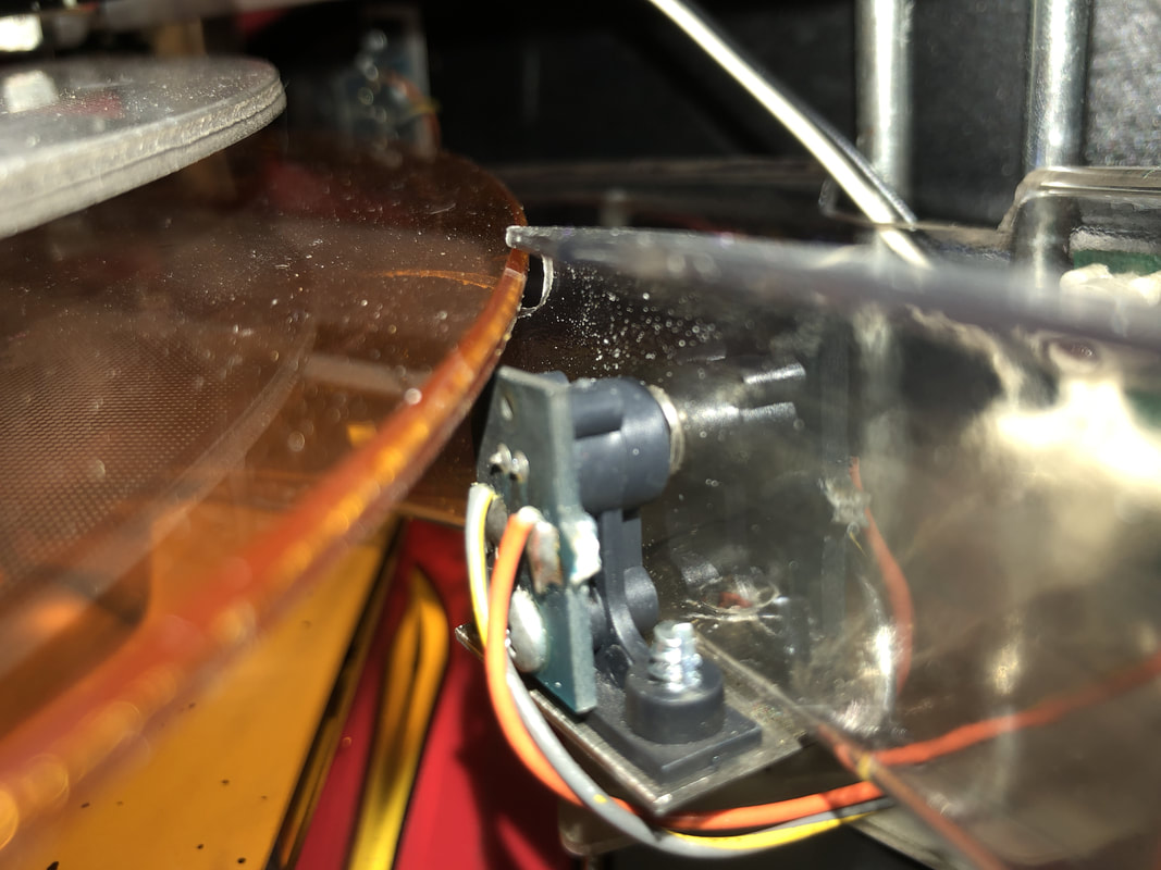
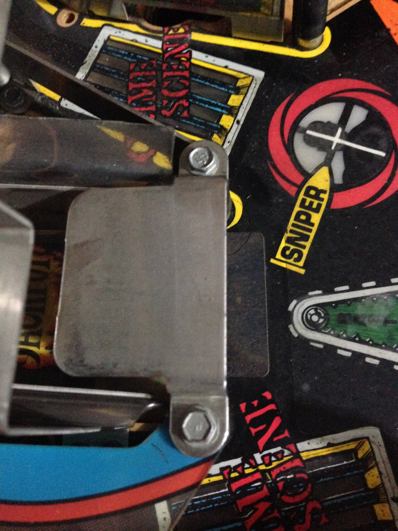
View showing the clearance between the ramp, opto and Deadworld ring after sanding of the ramp.
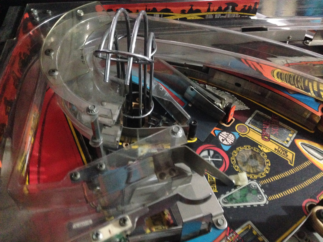
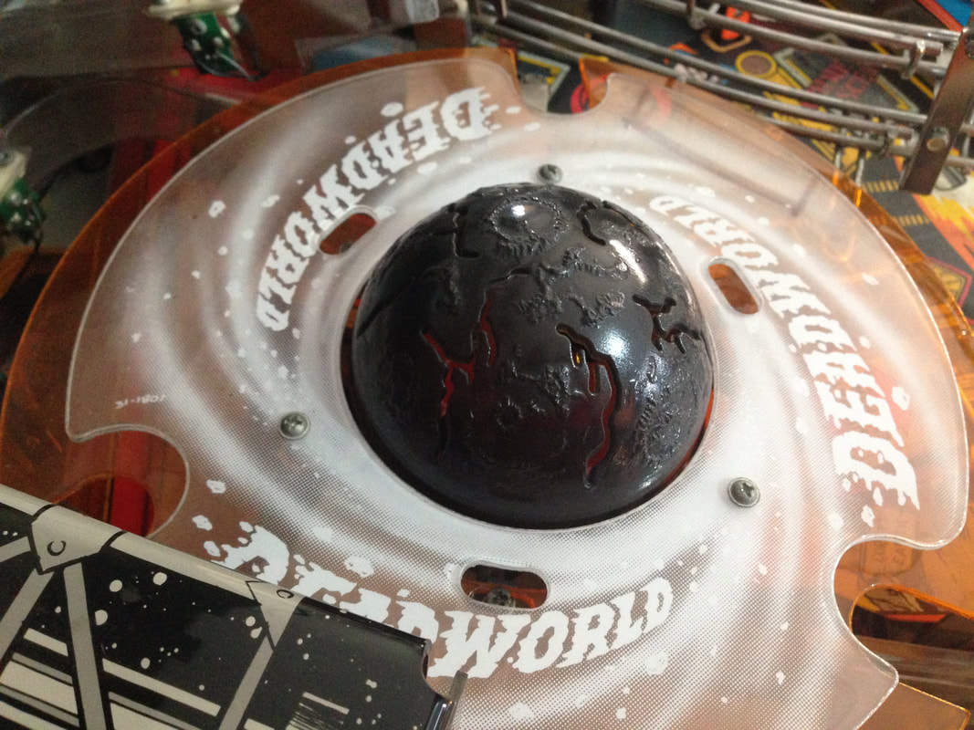
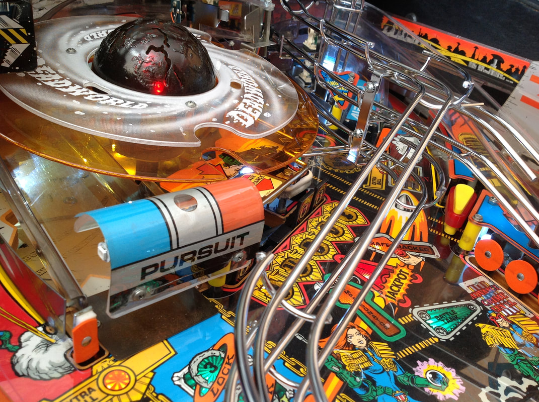
At this point the Deadworld could spin freely through an entire revolution and pick up and drop balls without issue. And that was the end of my Deadworld saga! 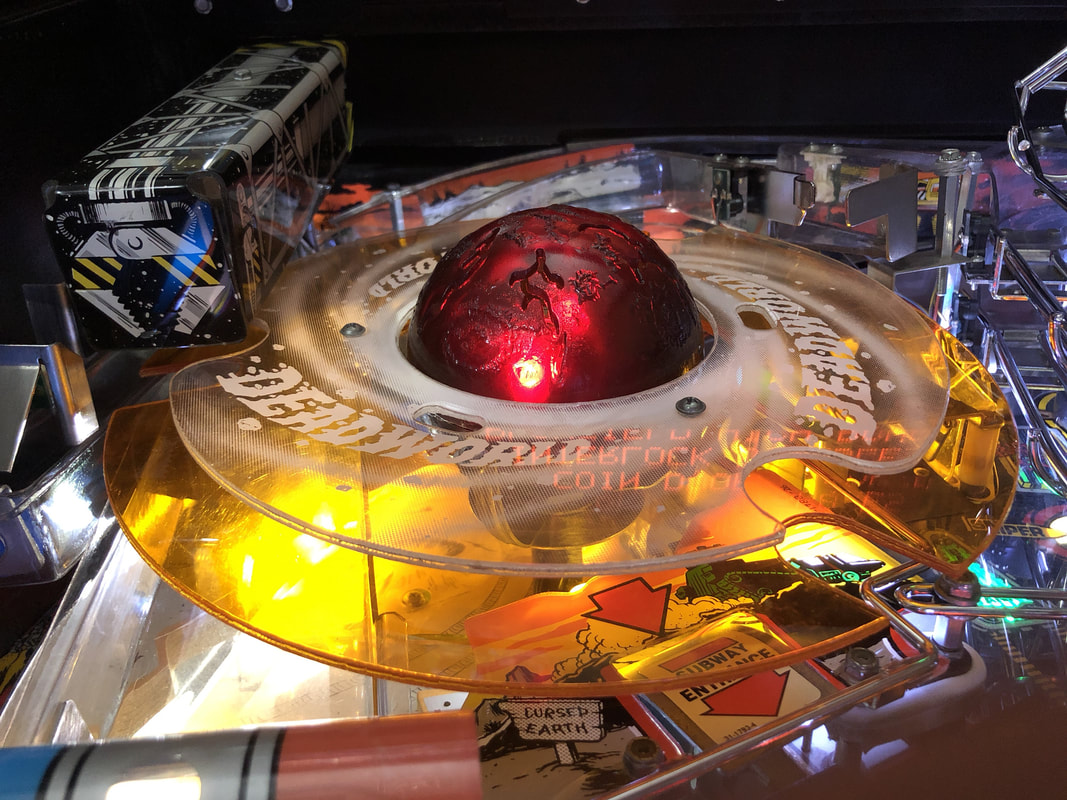
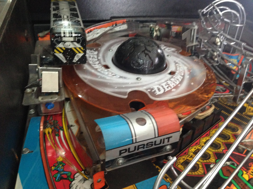
The end result of the Deadworld saga - fully rebuilt multiple times!
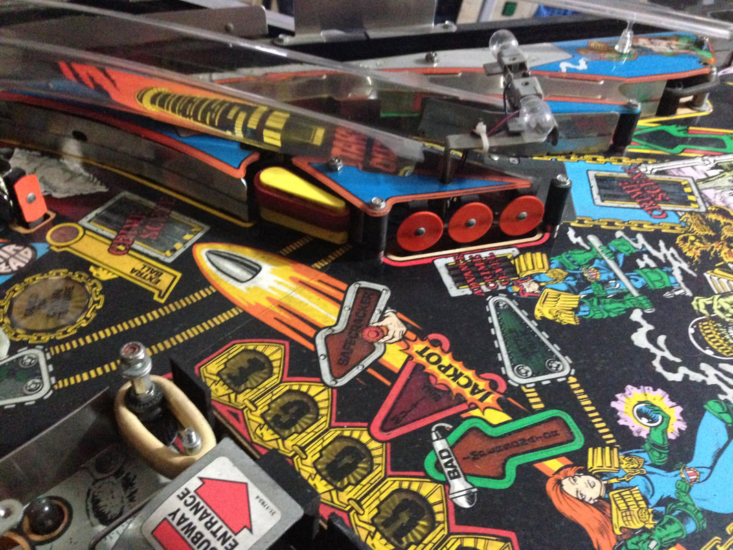
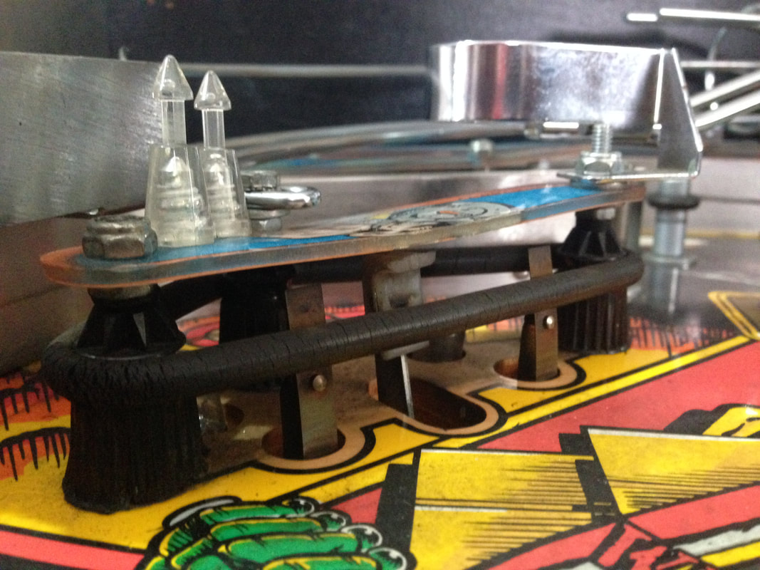
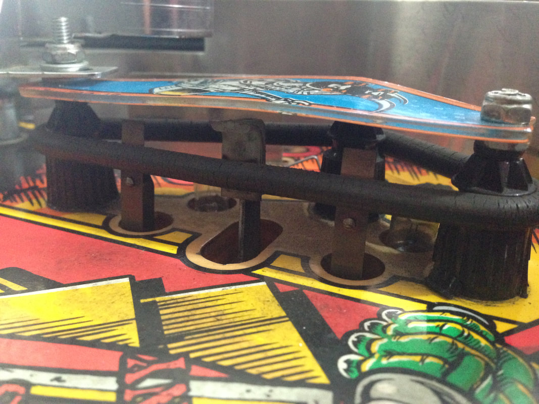
Another thing to note about the orange Deadworld ring is its orientation. It can be installed two ways, with the "slots" in the ring facing towards the front of the playfield or towards the rear. Photos on IPDB depict the ring in both orientations. The manual depicts only the prototype ring plastic with holes instead of slots (see below). So I'm not sure what the "correct" orientation actually is.
I found it best to angle the slots towards the rear of the playfield, which allowed the balls to sit nicely in the slot while the crane picked them up. Having the ring the other way up allows the balls to roll out of the slot before the crane has a chance to pick them up. Your mileage may vary, but it doesn't matter at the end of the day because the balls will still roll out of the Deadworld and onto the playfield if they get missed by the crane for whatever reason. There is one main thing you can do to mod your Deadworld. In the original prototype game, the Deadworld actually held onto balls that were diverted into it (i.e. it held the balls as physical locks instead of virtual ones). So when you locked two balls, those two balls were held on the orange Deadworld ring (part no. 03-8867) while it was spinning around, until you locked the third ball. At that point the crane picked them all up and dropped them onto the playfield for multiball. Here's a video of the mechanism as it was originally designed: It's a cool mechanic that was apparently removed after one distributor raised concerns regarding the reliability of the mechanism. And like so many other cool pinball mechanism ideas, it was removed from the final game. However, all you need to restore the prototype Deadworld is a modified orange ring (with holes instead of cut-outs) and a game ROM programmed with the prototype Deadworld functionality. The most popular version of the mod is that sold by Pinbits. Installation is pretty easy and is covered fairly well in this guide and on Pinball News. I haven't installed this mod on my Judge Dredd yet, but may very well do so in the future, as it's damn cool. Artefacts on display
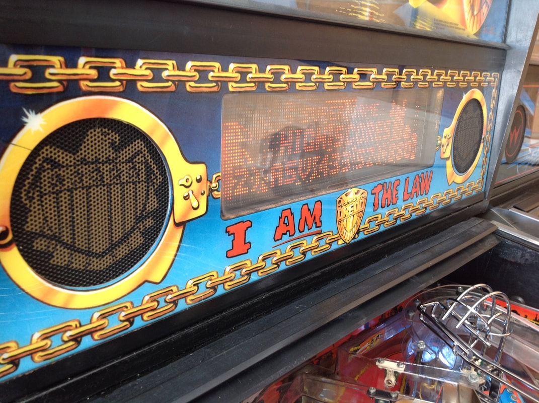
This was not the first time I had had issues with a display on Judge Dredd. My first issue was fixed several months before I properly started the restoration. That was a relatively simply one associated with a failed ROM on the display driver board.
Soon after I finished the restoration completely, I started seeing another display issue. The display would randomly start displaying a cloudy pattern, sometimes after several hours of play, or sometimes immediately after startup. Restarting the game sometimes fixed the problem, sometimes not. The first thing I checked were the voltages supplied to the display from the display controller board. All seemed OK. The issue looked like artefacts created by outgassing or too much voltage being driven to the display. Pinwiki has a great section with images showing how each of these issues can manifest. A really helpful tool I keep on hand for diagnosing display issues is a high voltage section piggyback board. I have one made by Video Penny, but there are various others available including one manufactured by Homepin. These boards entirely replace the high voltage section of the display driver board, so they're handy for when components fail and you need to troubleshoot where the issue lies. Installing the piggyback board in Judge Dredd stopped the display artefacts from appearing. So, that was a good indicator that one of the components in the high voltage section was out of spec. 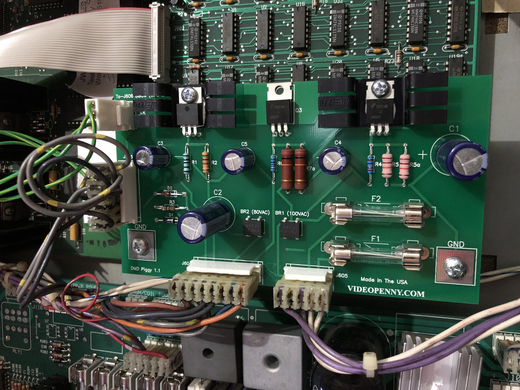
High voltage section piggyback board installed.
So, it was time to rebuild the high voltage section of the original board. This is a fairly laborious standard operating procedure which I covered in a separate blog post. Thankfully, after rebuilding the high voltage section, the display worked without issue. Hooray! Burned general illumination connectors
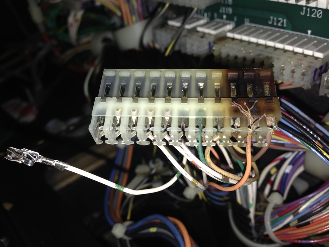
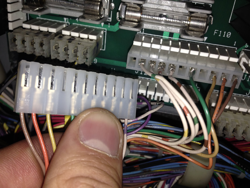
Another common issue that I find on most machines with original connectors and pins. Both connectors J120 and J121 had evidence of heat damage to them. Judge Dredd has a lot of lamps on the playfield as well as the backbox, so I suppose this is why both of them were affected. Both connectors were removed and recrimped with trifurcon terminals and installed into new housings. These will keep the lamps going for years to come. I also replaced the header pins for better reliability.
Wear spots around inserts
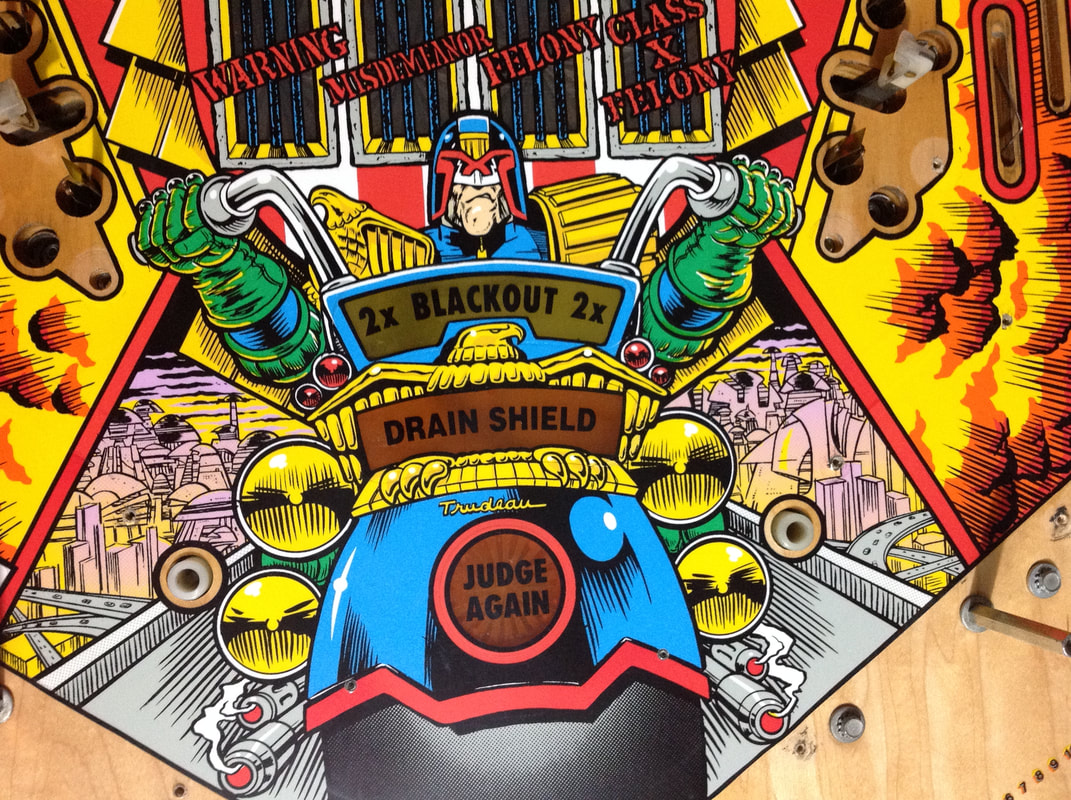
Any game with inserts close to the flippers is prone to insert and artwork damage as the balls spend most of their time around the flippers. "Hotdog" inserts are renowned for this as their shape makes them susceptible to lifting. This isn't helped when flashers are used behind the inserts - if they lock on, the insert will warp.
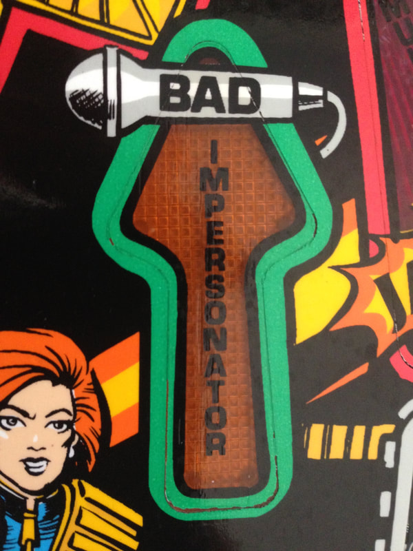
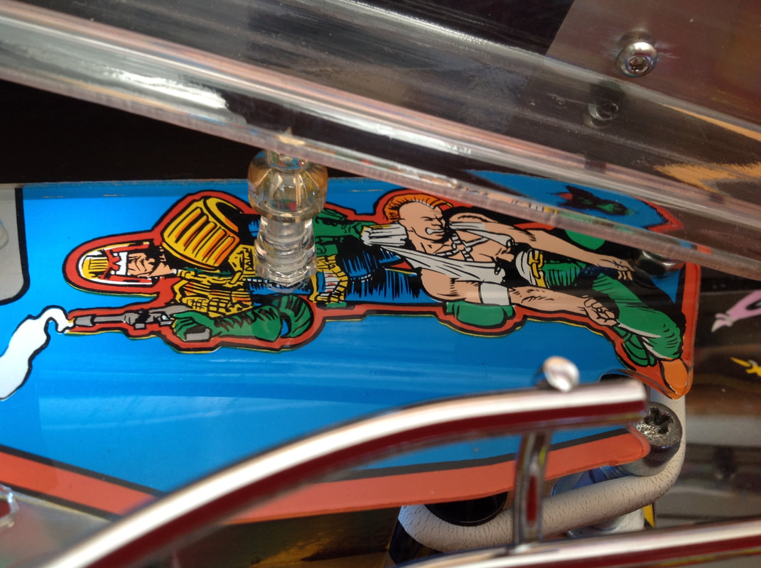
The Drain Shield insert on Judge Dredd was worn on the bottom right corner as a result of a slight raise in the insert causing balls to rub the artwork off. This section was mainly yellow and black, so it wasn't too hard for Fiona to touch up. 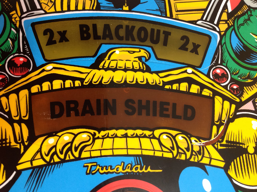
Drain shield insert before touch-up.
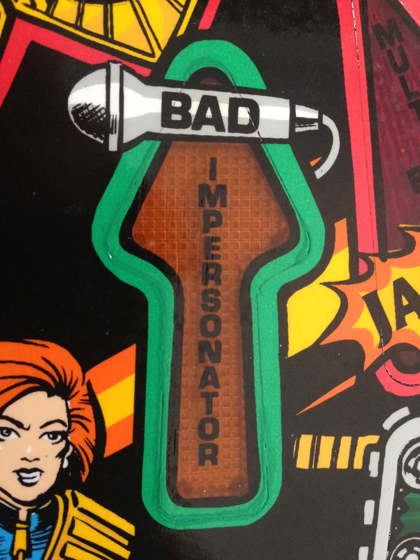
The lines in this area necessitated some brushwork instead of airbrush spray. The yellow on the eagle is actually two tones, with the slightly darker yellow tone representing shadow. The yellow was a great colour match with Createx opaque yellow, while the darker yellow was made with opaque yellow mixed with several drops of opaque red mixed in to create the darker shade. The lighter yellow went down as a base coat, with the darker yellow on top and black as the final layer. The black outlines were done in opaque black. The final result looks pretty good, and under the playfield protector, it is hard to spot. 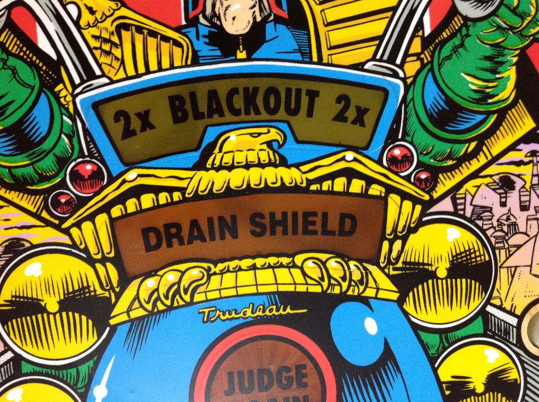
Drain shield insert after touch-up.
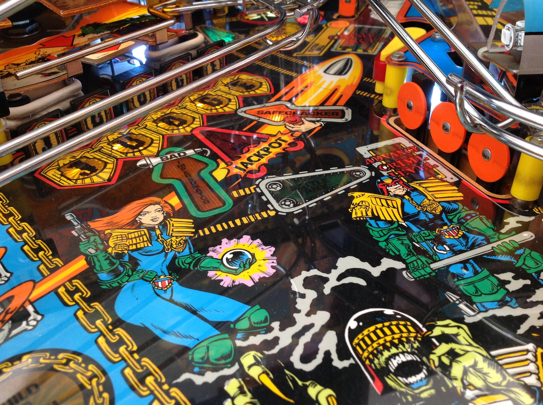
There were a couple of other inserts on the playfield with very slightly worn edges. The first was the jackpot insert in the centre of the playfield and the second was the meltdown insert in front of the captive balls. These just needed a touch of opaque red and opaque light green, respectively, to fill out the insert outlines. Otherwise, they were in good condition.
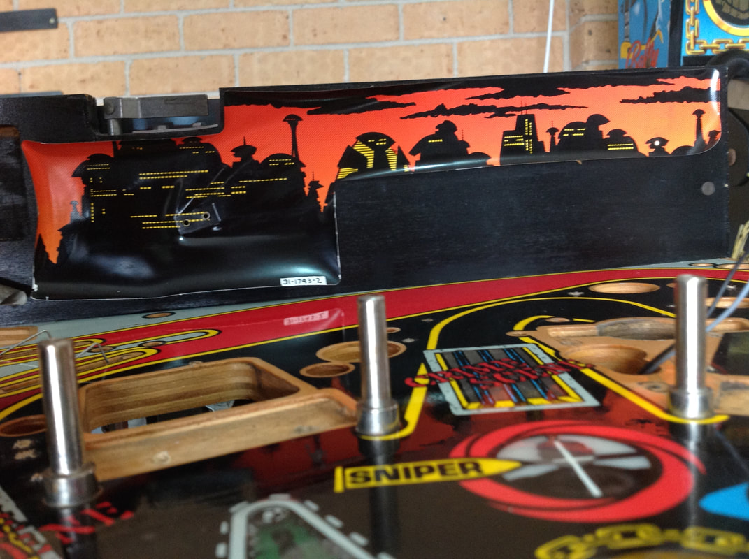
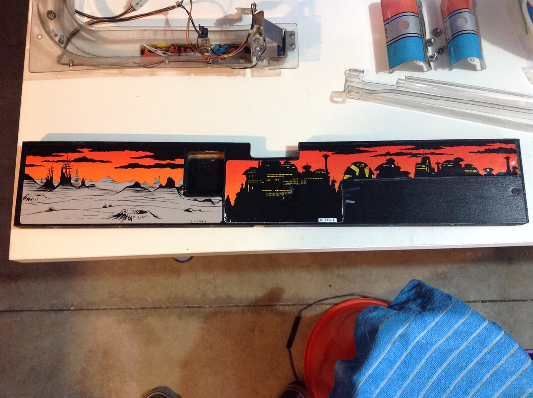
Back panel decal warping
The decal stuck to the back panel of the playfield was heavily warped and had started to peel. It looked really ugly, and is hard to buy new, so I took it off in order to fix it. Use alcohol to mobilise the decal adhesive and pull it off without tearing it to pieces.
Once the decal is off, clean off as much of the adhesive as possible. This just makes it easier to work with while you're trying to flatten it. Then, flatten the decal using flat, solid weights. I used old textbooks for this as they're big and heavy. Use some sheets of greaseproof paper to keep the backside of the decals from sticking to anything. Check on it every now and again and take it out once it's well and truly flat. This decal took about two full days to flatten out. At this point you can just stick it back onto the back panel with your choice of adhesive - easy peasy.
Lamp matrix column not working
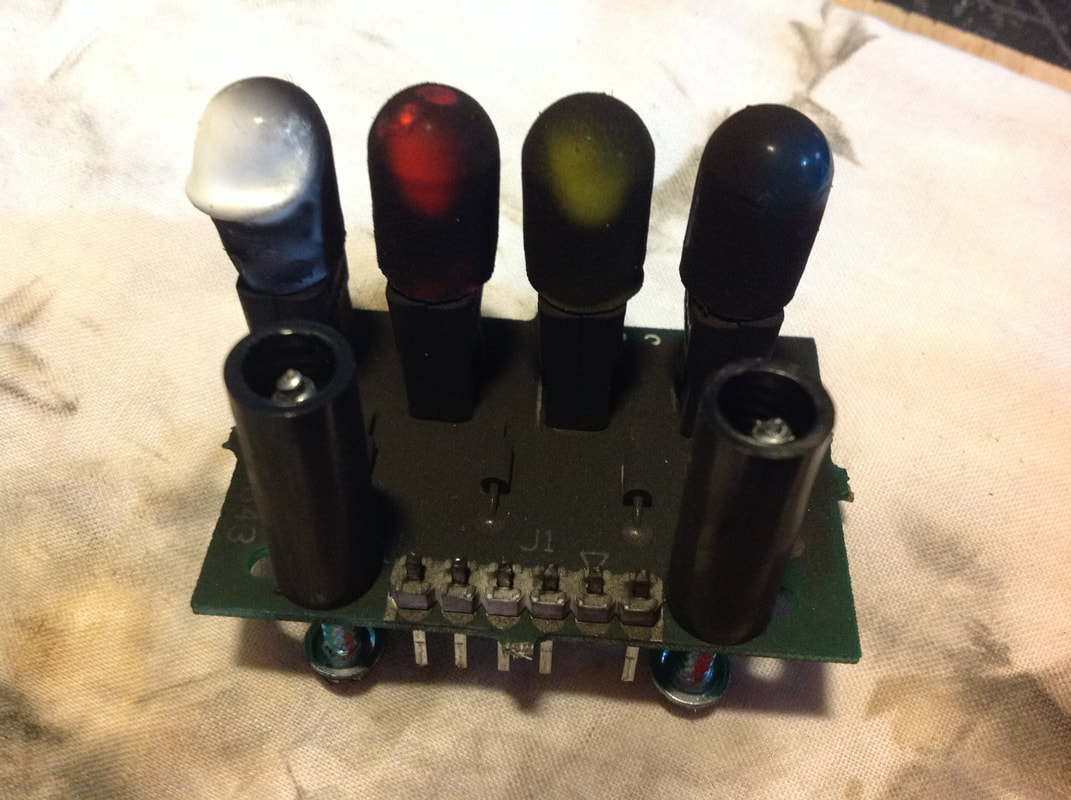
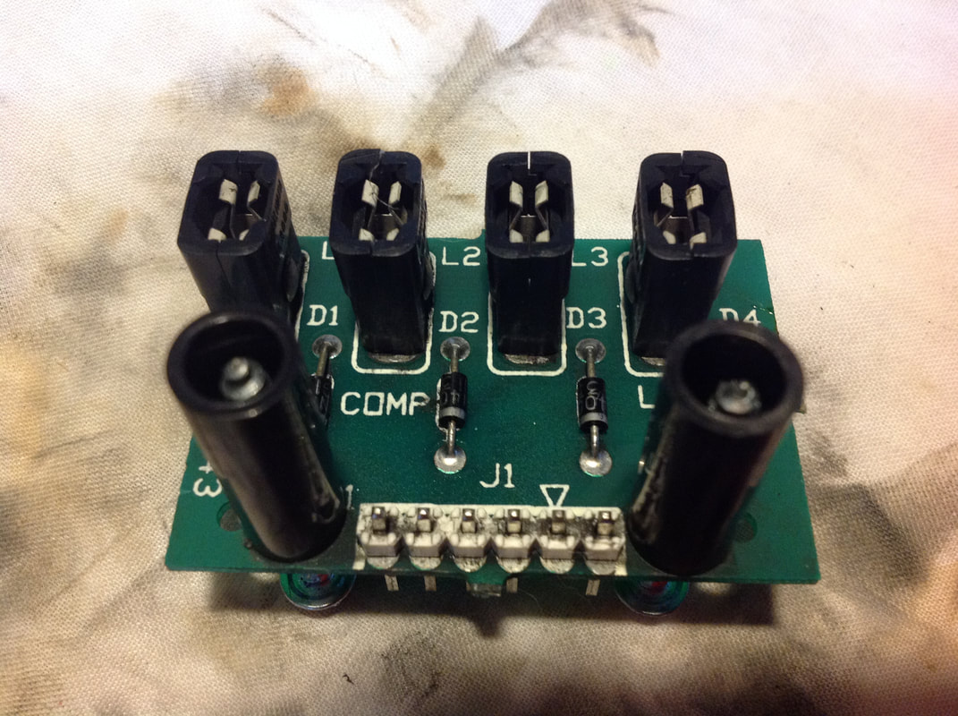
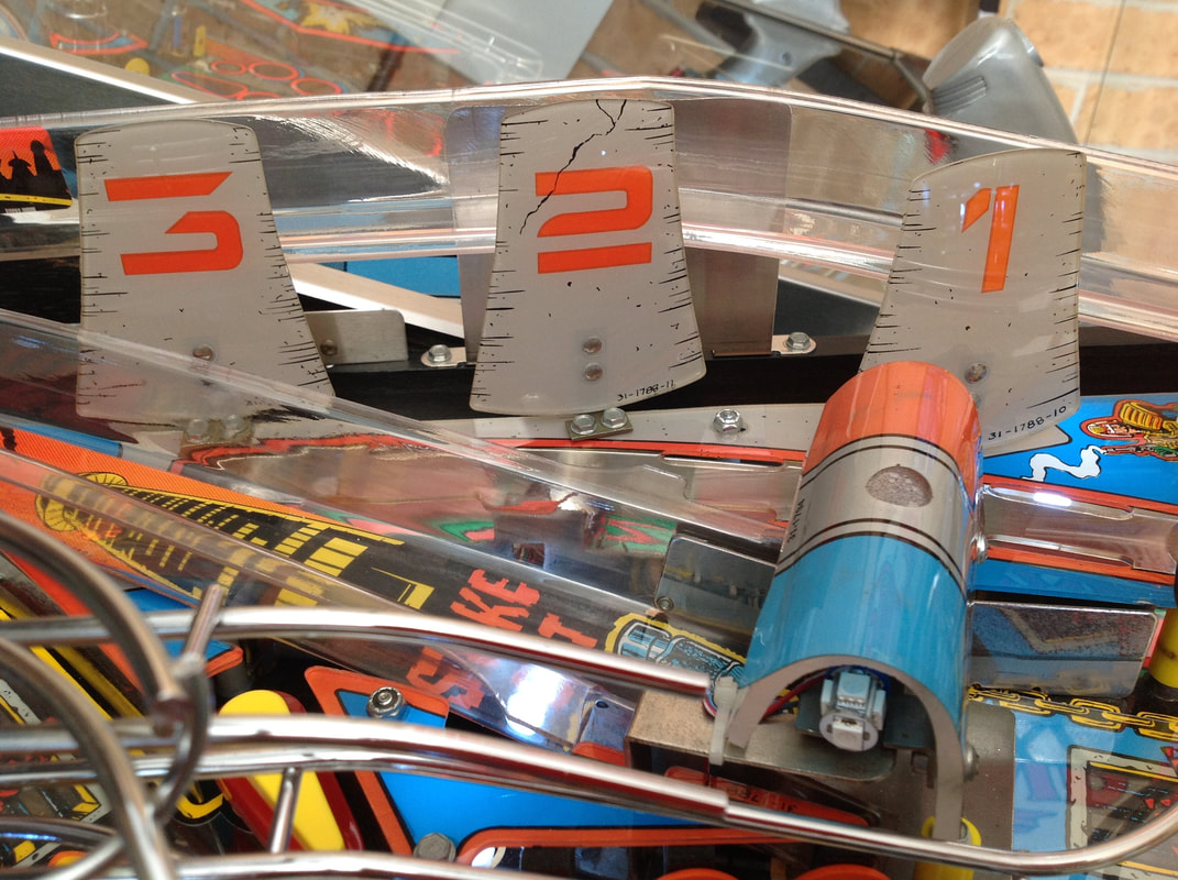
I had an issue with a series of controlled lamps on the playfield not lighting up which turned out to be an interesting troubleshooting exercise. The non-working lamps included Crime Level 1-4, meltdown, bad impersonator, and battle tank. These lamps were all in column 4 of the lamp matrix. The fact that the issue was common to an entire column was the first clue. I checked transistor Q95, which controls this column, and it tested fine. Continuity from the backbox (J137-4) to the lamp board under the playfield was also good. To narrow the issue down to a playfield or board issue, I tested the lamp matrix column outputs using a simple lamp socket test jig, as detailed in Terry B's guide. The video below shows the results.
Column 4 was not being driven by the power driver board, which confirmed that the issue was with the power driver board rather than a wiring issue on the playfield. I had already eliminated Q95 as an issue so I started looking further up the power chain. The lamp matrix circuit upstream of the TIP107 transistor consists of a ULN2803A transistor and LS374 and LS240 logic flip-flops. So I started probing these components with my meter to see if I could find any issues. There is a guide on Pinwiki that covers the testing procedure for multimeters. Note that integrated circuit testing is much easier with a logic probe, which allows you to test the outputs of the chip pins easily. However, all I had at this point in time was my multimeter. So, off we go... I tested the pins of U18, placing the red probe on the ground pin (U18-10) and probing the other pins in sequence. Most of them read similar voltages except for U18-18, which read only 0.32 volts. Hmm! This pin is connected to Q95 down the chain, which drives column 4. Sounds like we may have a culprit! 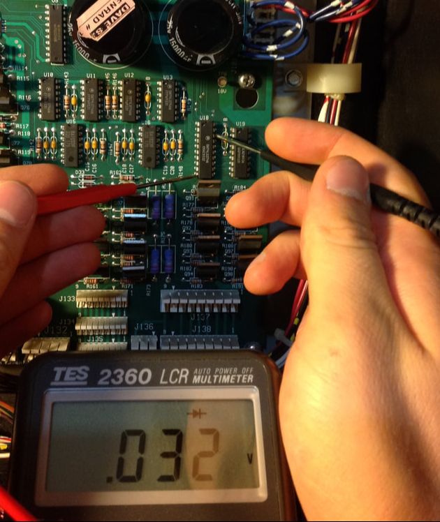
Testing pin 18 on U18 and reading low voltage.
Unfortunately, it's never as simple as that! While U18 may have been the problem component, it is fed by signals from U9. So the short may have been originating from either chip. The only way to verify for sure is to desolder one of the pins in the problem circuit and retest; the faulty component will still show a short. So, I went ahead and desoldered U18 completely. I lifted a couple of traces in the process and learned first-hand why you should always clip the component from the board before desoldering the legs individually. Even with a good desoldering gun, it's easy to mess these the through holes up. With U18 out, pin U18-18 actually tested OK. This suggested that it was not faulty as initially thought. So I directed my attention to U9 and used the same testing procedure on each of U9's pins. Sure enough, I found another suspect pin that gave the same low 0.32 volt reading: U9-8. Surprise, surprise; this pin is directly upstream of U18-18! This turned out to be the defective component. I ordered some replacement LS240 chips (RS Components) and some LS374s (RS Components). These will come in handy for future board repairs, too. After socketing the new chips and resoldering them in place, column 4 lit up like a Christmas tree. Hooray! Topper lighting mod
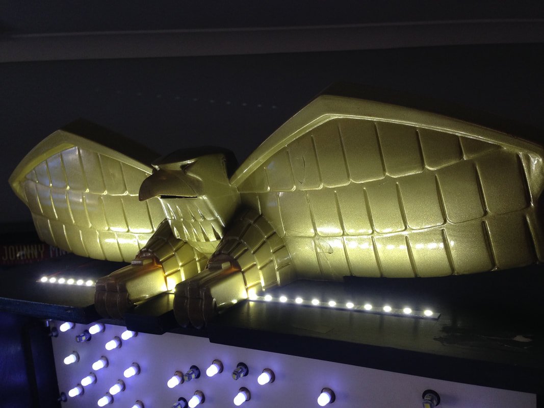
As I described above, the eagle topper is pretty cool to look at. Unfortunately, a lot of the time it goes unnoticed. I decided to draw some attention to it by installing a strip of LEDs underneath it, shining directly up into the wings of the eagle.
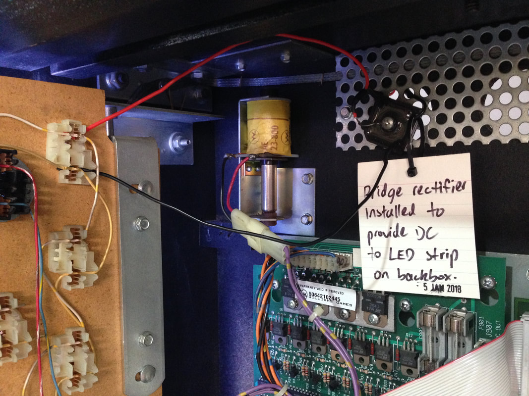
I had grabbed a bunch of 6V LED strips on eBay to play around with and this was the perfect first project to try them out. These strips are sold in 50cm lengths, and luckily, 50cm is the perfect size for this. A strip this size fits right underneath the topper, and as the strip is quite thin, the eagle's legs just sit on top of it. No cutting the strip is necessary and no need to use multiple small lengths. Next was the task of finding a power source for the LEDs. I wanted these lamps to be on all of the time, so I hooked into a nearby general illumination circuit. I needed to lengthen the wires attached to the strip, and routed them through the grille at the top and rear of the backbox. I connected them to the wedge lamp socket in the top left corner of the backbox. The good thing about these types of sockets is that the wires are just punched in - similar to an IDC connector. No extra plugs to worry about. I turned the game on to see what would happen. The lights lit up the topper nicely, but there was one annoying problem... the LEDs were strobing badly. This was because the LED strip I purchased was DC, while the lamps in the backbox are supplied AC current. Alternating current is shut on and off repeatedly (sine wave). This was causing the strobe effect as the LEDs were basically being turned on and off 60 times a second. To fix this, I needed to supply the strip with direct current. Fortunately, I had plenty of spare bridge rectifiers in my toolbox for this. The GI lamp circuits in WPC games run at about 6-7 volts at 5 amps. Any bridge with specifications over these figures will work. Standard bridges used on power driver boards are rated at 200 volts and 35 amps - plenty of wiggle room. I found that the neatest place to mount the bridge was on the backbox grille. It can be attached with a screw and a nut on the other side of the grille. Next I just soldered everything together. The positive and negative leads from the LED strip were attached to the positive and negative leads of the bridge, respectively. The wires from the lamp socket were soldered to the other two bridge legs (no specific orientation). The wires were all cut to size so there was no messy wiring clogging up the backbox. This was one of the neatest mod implementations I've ever done! After installing the bridge rectifier, the strobe effect was gone and the LEDs were consistently lit. The eagle looks much better now. But something tells me it would look even better if it was a brand new eagle with shiny gold paint. Maybe I'll have to add that to the shopping list!
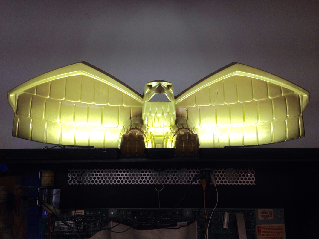
Installed and strobe-free. Shiny!
Drop target decals
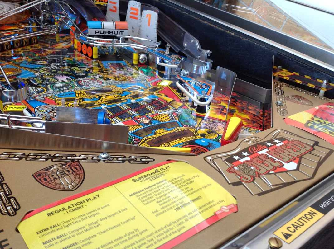
The drop targets on Judge Dredd are plain black plastic, which in my opinion looks pretty dull for a playfield feature which is in the very centre of the playfield. There are a few different target decal designs available, and having them installed on the targets with similar designs to the lamp inserts makes for a nice effect. I grabbed a set from Bay Area Amusements. I liked these ones as the design matched the inserts in front of the drop targets on the playfield. There are a few different designs available, so have a look around and see which ones you like.
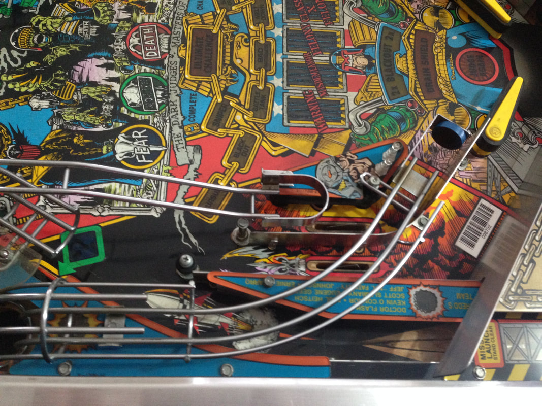
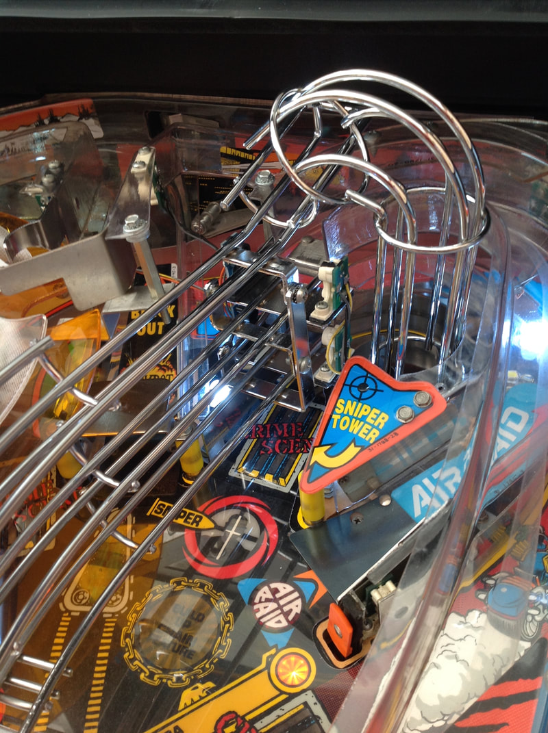
Left ramp Cliffy protector
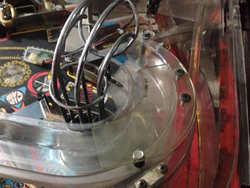
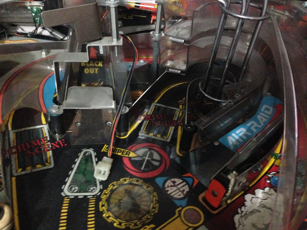
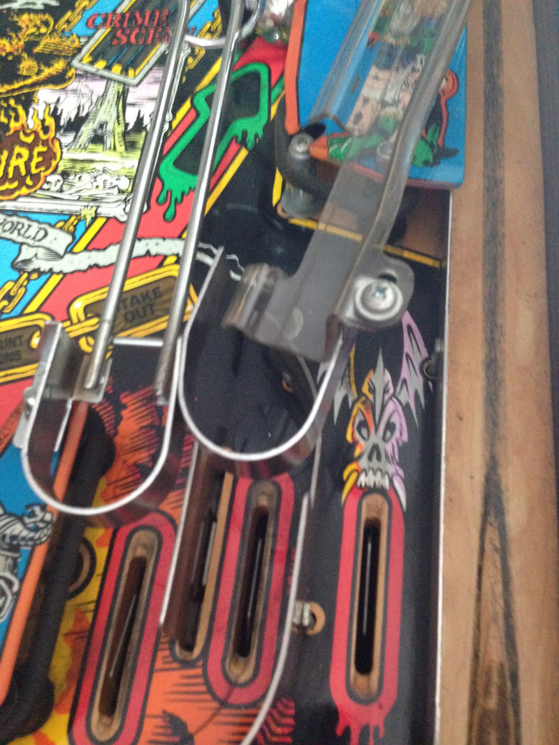
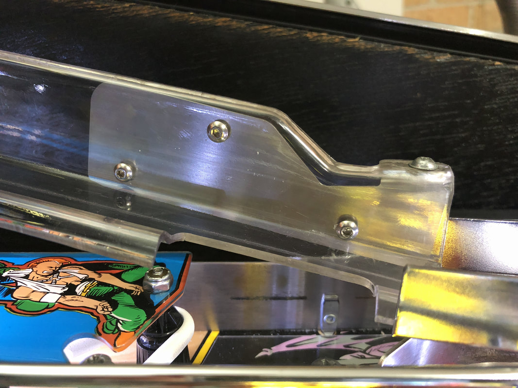
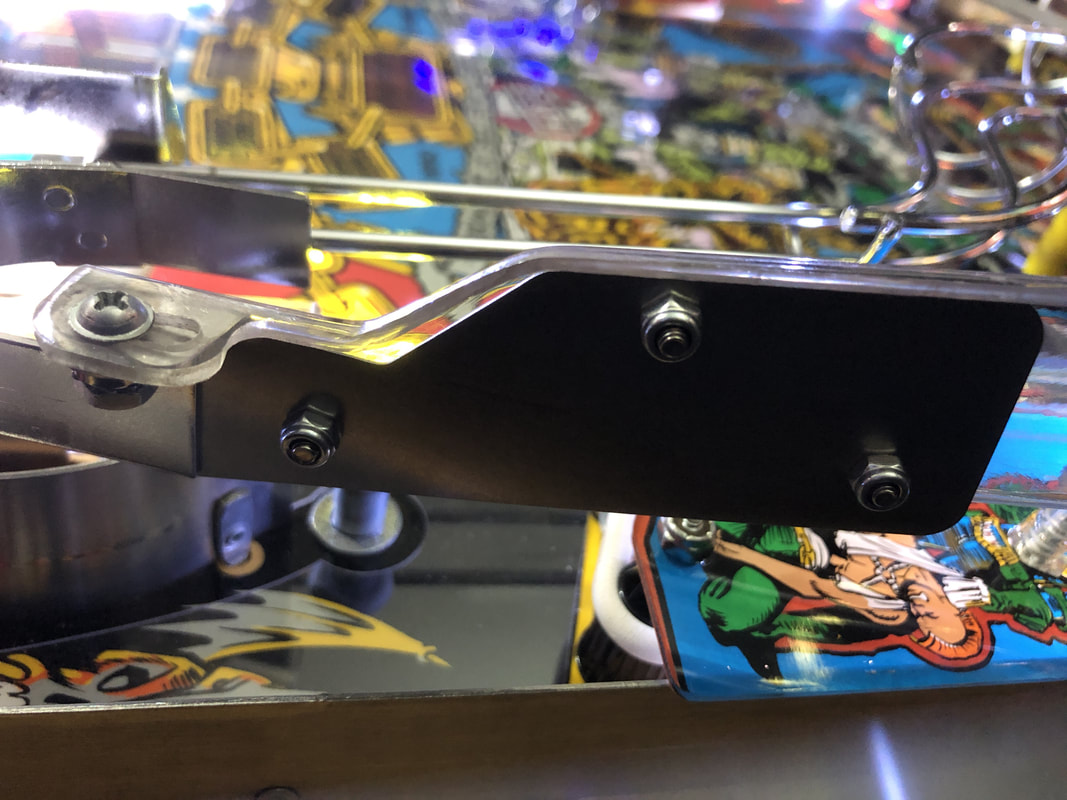
One thing you will probably notice when playing Judge Dredd is that the end of the left ramp, where it mounts to the right slingshot, shakes a lot when the ball travels over it. I found that the screw that secures the ramp to its mounting bracket allows for a bit of movement in the ramp even when fully tightened. The end of the ramp seemed to flap around a bit when the ball exited it.
This is a common issue and the reason why a lot of Judge Dredds have cracks in this section of the ramp. Luckily, there is a Cliffy protector designed to address this problem. My ramp was in perfect condition, so I installed the Cliffy to ensure it stays that way. However, it's still a good idea to install a protector even if your ramp is broken, as it will keep the pieces secure. There are some good images of such a reinforcement on Cliffy's website, linked above. It was a bit odd having to drill holes in an otherwise perfect ramp... putting holes in intact pinball assemblies is generally not what you want to do! However, the way this ramp mounts means that there's no other effective way to secure the bracket. Place the protector on the ramp and mark the position of the holes before you drill to make sure you install them in the right spots. You can use rivets instead of the supplied screws and nuts if you want a more professional finish. I used the supplied screws and nuts, which I think look just fine.
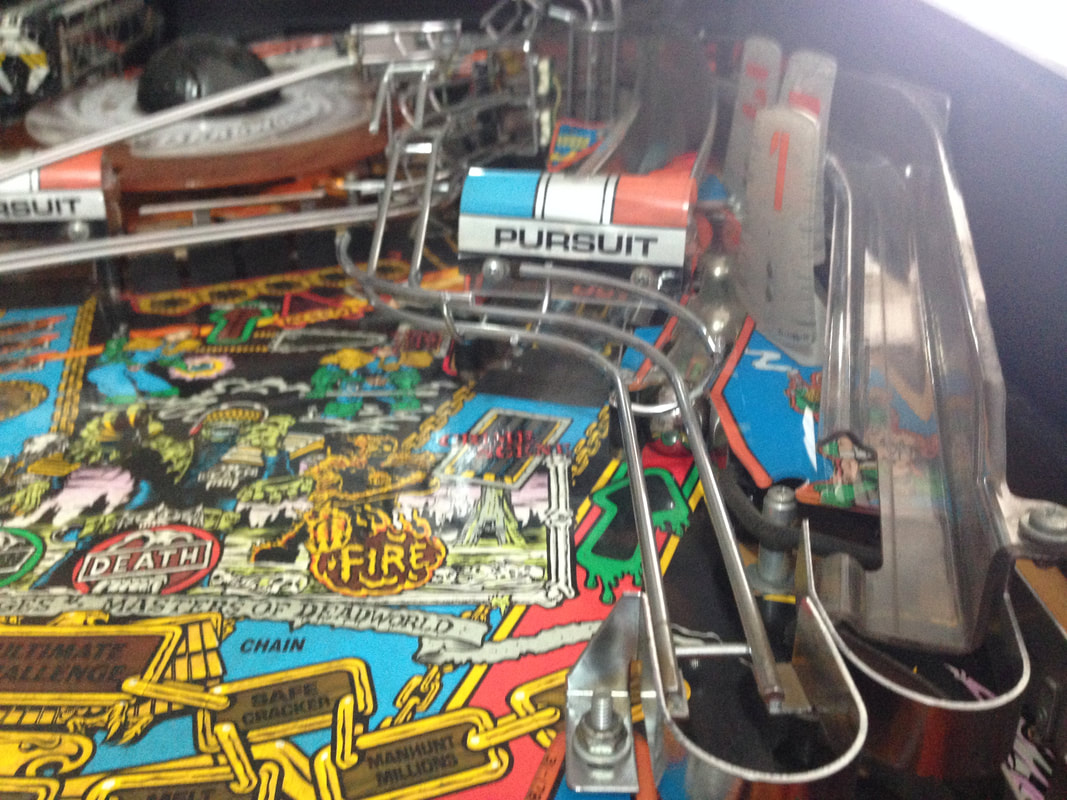
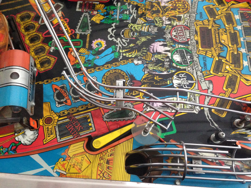
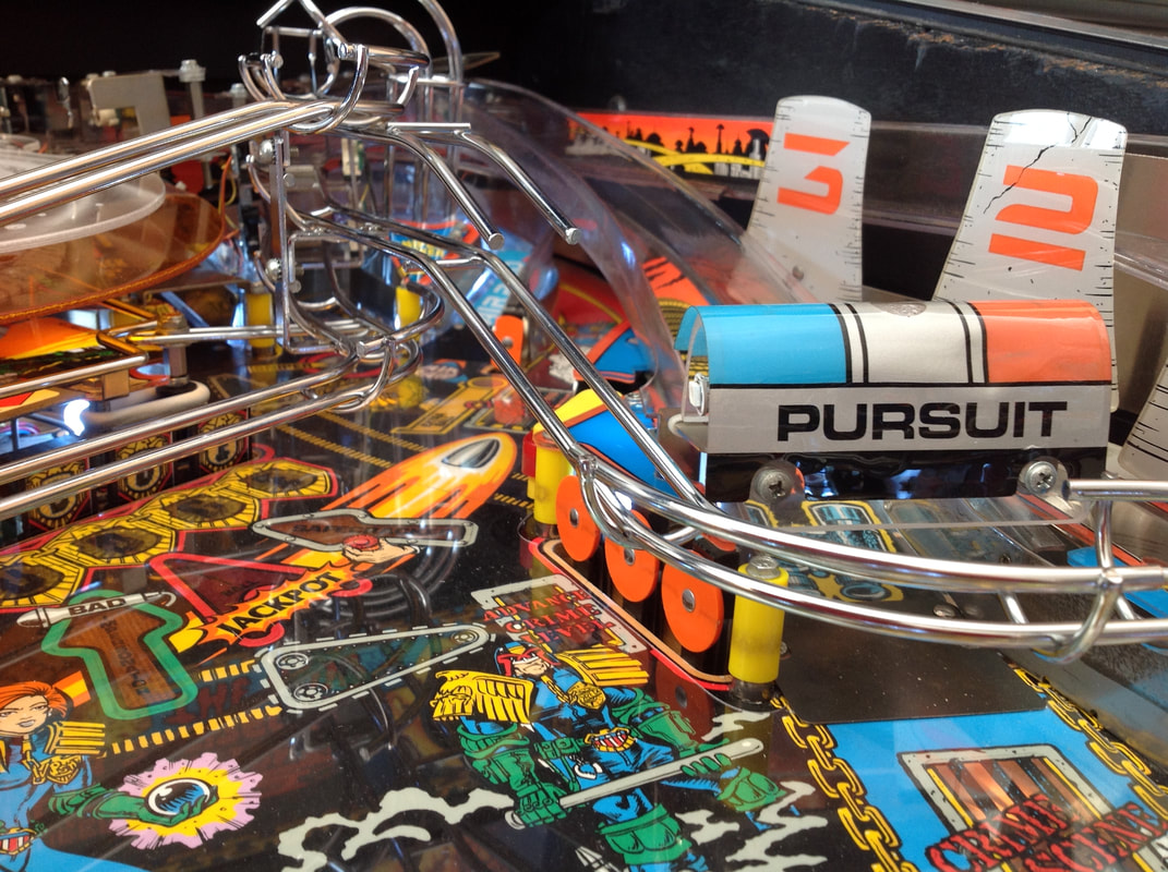
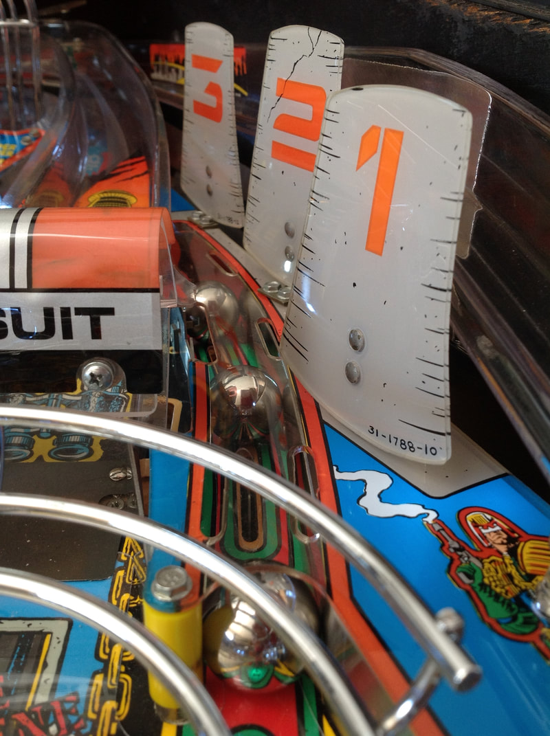
Pursuit plastics, decals and lamps
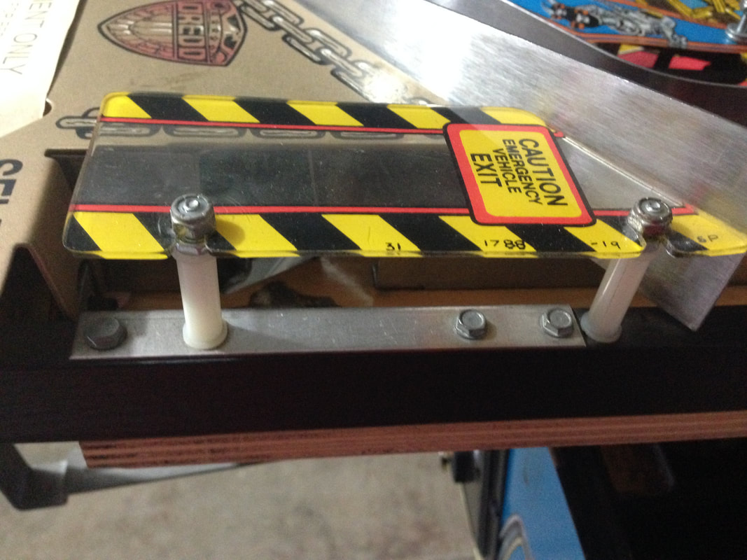
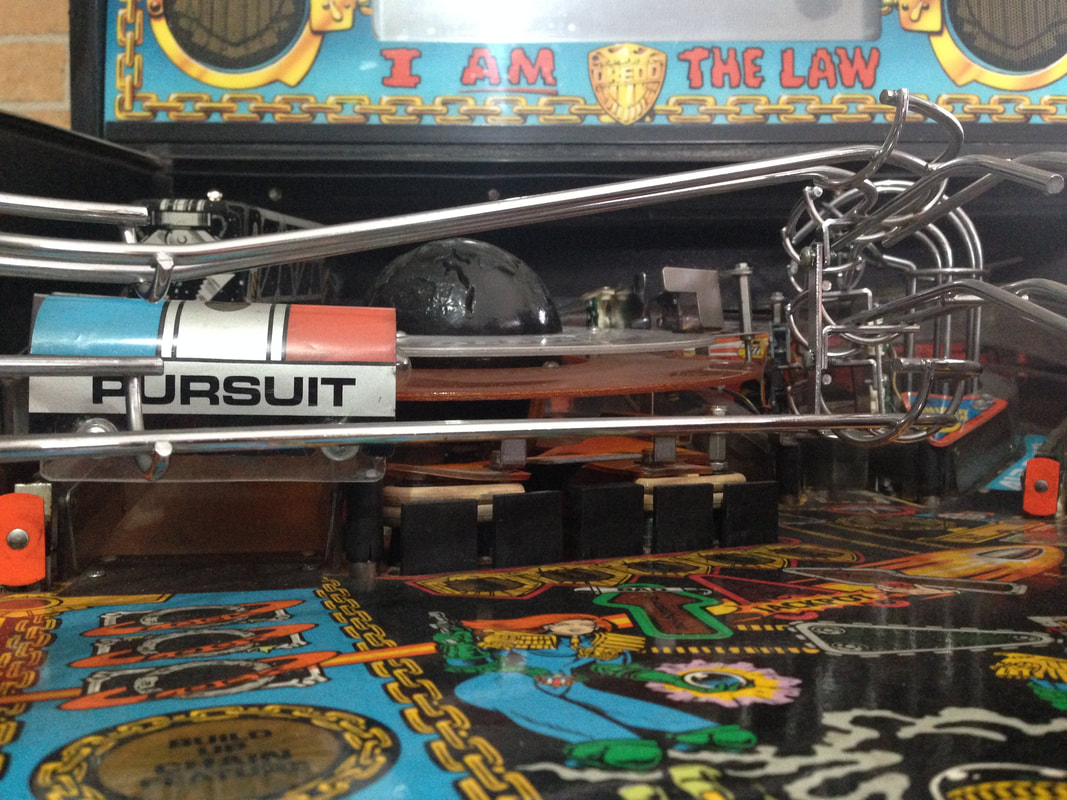
Above the entrances to the left and right ramps are the pursuit flasher assemblies (part nos. A-16790 and A-16791, respectively). These assemblies are problematic because they often get smashed by airborne balls, and are very difficult to find replacement parts for. They basically consist of a metal bracket with two flasher bulb sockets, covered by a transparent, curved plastic, with a decal over the top.
The assemblies on my game were not entirely original. The left mounting bracket was fine, but the one on the right had been snapped. The section of the bracket that screws onto the playfield had been replaced with another piece of metal which was riveted to the original, remaining piece. It worked well enough, and was mostly hidden under plastics, so there was no reason to replace it. The curved plastic pieces, however, were both unoriginal. It looked like the previous owner had made up his own by bending some polycarbonate to shape. It actually looked really good, and the plastic was much thicker than the original, which means they will hopefully be more impact-resistant. I guess this is one of those rare instances where a pinball repair is actually done properly! 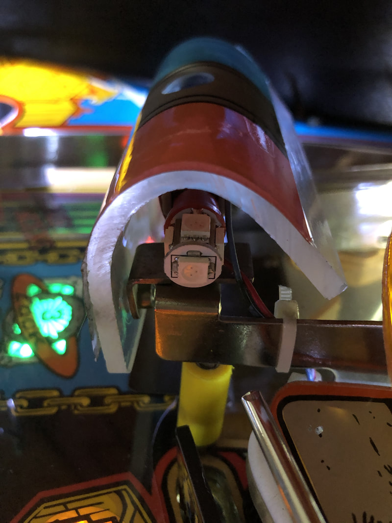
Unoriginal replacement pursuit plastic. Thicker and stronger than the original.
While the decals looked to be original, they had obviously been removed from the old plastics and transferred to the new ones. They hadn't been stuck down very well and needed a bit more adhesive applied to keep them in place. I was lucky in that the assemblies were either intact or properly repaired on my machine. Most people aren't so lucky, and are missing parts. Unfortunately, parts for this assembly are not easy to get locally. The metal support brackets are not currently available anywhere. The plastic covers only seem to be available at Pinball Life. However, the decals are available from a few retailers (Pinball Life, Ministry of Pinball, Marco, Pinball Center). Parallel lamp board sockets loose
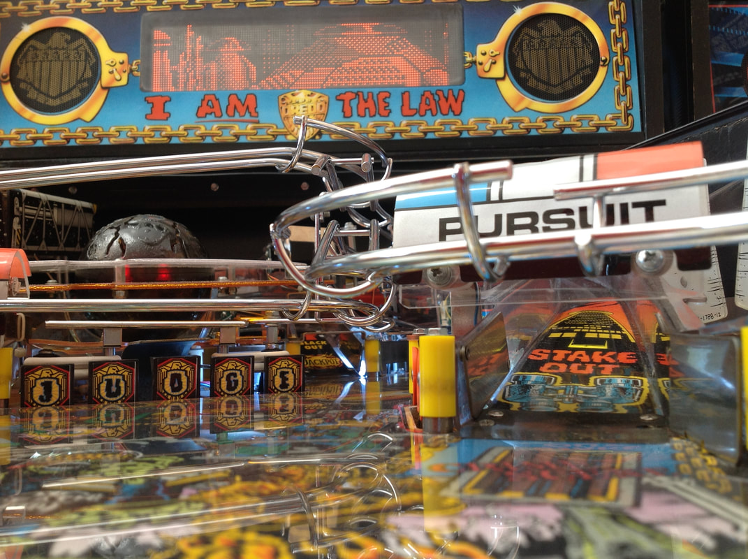
After fixing the lamp matrix issues affecting lamp column 4, I found that I still had issues with one particular lamp... the pursuit insert (leftmost chain link). This insert lit up occasionally, but was usually dimly lit, and would sometimes stop working altogether.
The wiring was all intact, so I looked at the lamp board itself. The header pins were in good condition, so no issues there. I replaced the lamp and the issue remained, so the socket was the next likely cause. This socket, as well as the socket on the opposite side of the lamp board, is actually mounted parallel to the lamp board surface. The sockets sit at a 90 degree angle (cantilever sockets) and are notorious for having their solder joints crack over time due to the pressure of inserting bulbs into the socket. Pinwiki has a section describing this common issue. And that was the case with this socket; the solder had given way and there was no longer a good connection between the socket and the board. Resoldering it fixed the issue. These sockets commonly break, too. Replacements are available (Mr Pinball). 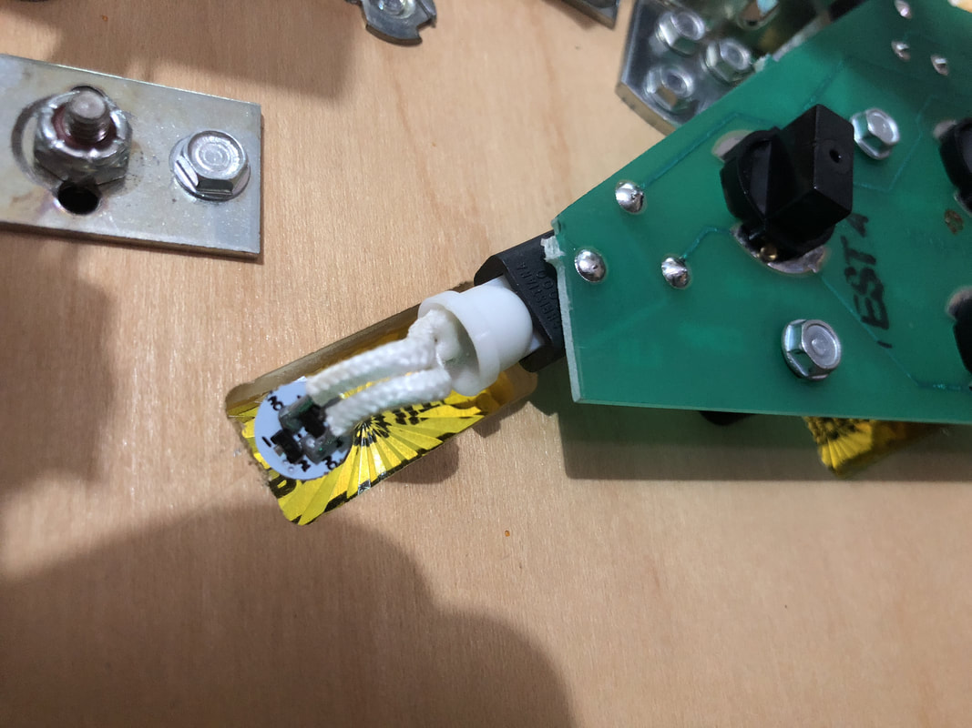
The pursuit lamp socket with new solder applied.
Sound board upgrades
This is a small upgrade I do on all WPC DCS sound boards. The ceramic capacitors at C37 and C45 are unnecessary, and were actually removed from the next revision of sound boards (WPC 95), as described on Pinwiki as well as on Pinball Rehab. I removed them both from the board. This cleans up the sound effects a little and makes the sound clearer. Game reset issues
At one point I was having some opto and sound board issues, which I managed to fix without too much issue. However, when I tried to boot up the game after fixing these issues, the game would not boot. I struggled to figure out why this started to happen when the game had been booting without issue several days before. As is usually the case, fiddling around in the backbox to fix one thing usually breaks something else! Reseating the ASIC chip seemed to stop the issue temporarily, but after playing for an hour, the game started resetting again. So, off I went to follow the Pinwiki game reset guide to narrow down the cause. I dealt with all of the easy stuff (reseating connectors) until I had to get the power driver board out and inspect some connectors and solder joints. All of them looked fine visually, but reflowed solder on J101, J102, J103, F113, and the LM323K regulator. One of these joints must have had issues, as the resets stopped after the solder was reflowed. In fact, I was now getting 0.25 V more at TP2 than before. Just goes to show that even visually perfect solder joints can be dodgy internally. Trough opto issues
WPC trough opto boards are notoriously unreliable, and the ones used on games between Indiana Jones (Williams, 1993) and Demolition Man (Williams, 1994) are even more susceptible to issues as the logic components are mounted to the boards and subjected to the same heat and vibration stress as the other components.
My initial problem was with the top trough opto (also known as the 'jam' opto, switch 87). This opto was intermittent, and would sometimes be triggered by a flipper activation or other vibration. This would send another ball into the shooter lane, which would then launch onto the playfield, for an impromptu two-ball multiball. This got annoying after a while, so I went into switch edge test to figure out what was happening. With the coin door closed so I could use the flippers, I started banging away at them. That's when I saw switch 87 registering false hits. So, time to inspect the trough opto board. The first thing I noticed was some dodgy wiring on the connector leading to the trough opto transmitter board. The wires had been pushed into the connector loosely and were partly hanging out. Also, two black wires were shoved into one terminal and two grey wires were shoved into instead of being inserted into individual terminals as per the schematic. I rerouted the wires according to the manual and spliced them together with an inline connector while I hunted further for the root issue (this wans't it!). 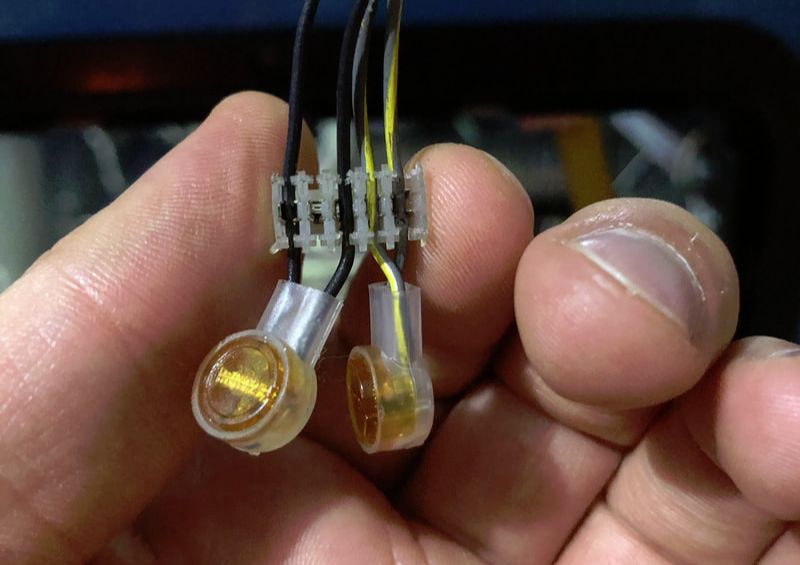
Proper wire layout of trough transmitter board connector.
The opto transmitter board on my Judge Dredd had been hacked up a bit before I got it, which was pretty typical of these boards. All of the resistors had been replaced previously and some of the optos were also unoriginal. I used a torch to verify all of the opto receivers were working properly. Then, I used a phone camera to check if the top trough opto was emitting any light. It wasn't, so I replaced it and installed the board back into the game. 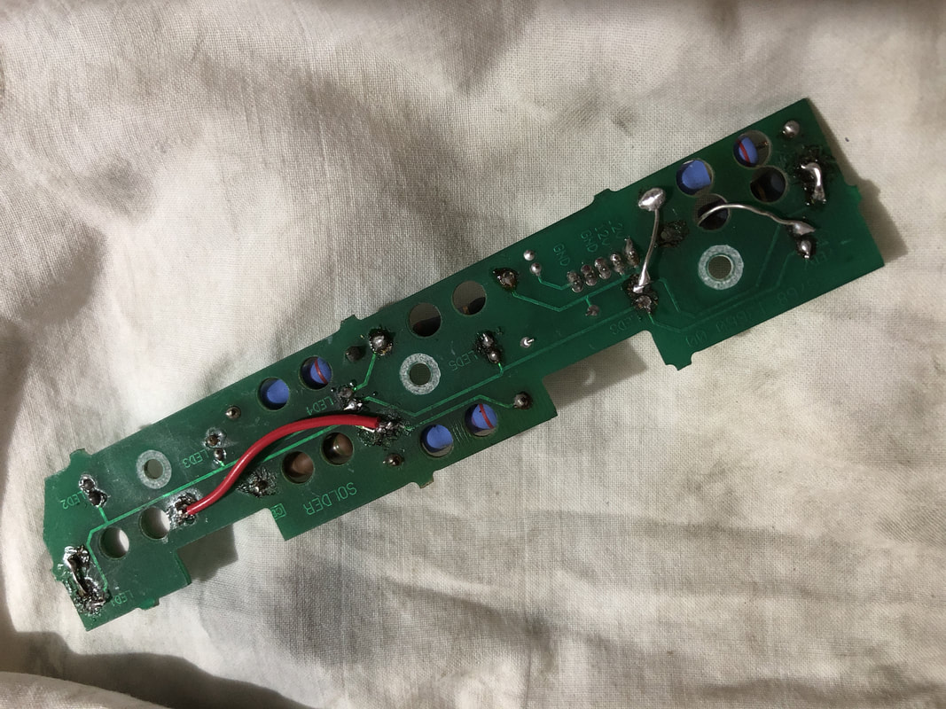
Solder side of the opto board. Lots of hacky wiring going on here...
Everything worked fine for a little while, until I started seeing the exact same issue again. And it was still the top trough opto that was triggering intermittently. I double checked all of my soldering and couldn't find any issues. At that point I started to look at the other traces and components on the board. I chased my tail for a few hours and couldn't find anything wrong. At the end of the day, I decided to check all of the components again. This time, I didn't get a reading on resistor R1, which is connected to the top trough opto LED. This was weird because I checked the resistor earlier and it gave me a good reading. I pushed on the resistor and found the source of the problem - the resistor had cracked where the leg joins the body of the resistor and it was only making intermittent contact. This was why I got a good reading earlier but a bad one later on. This is a common problem with these boards, caused by the heat of the resistors. I replaced the resistor with a higher rated 5-watt cement resistor (Jaycar), compared to the original 2-watt resistor, which will give it some extra heat-sinking capacity. While this was a tricky problem to find, it shows that it is a good idea to physically poke components when testing them instead of just relying on your meter! 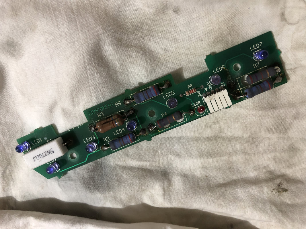
Component side of the trough opto board with new resistor at R1.
Filthy lamp boards under playfield
I don't know what it is about the small Crime Scene lamp boards under the playfield on Judge Dredd, but they were the filthiest components I have ever seen on a pinball game. Even dirtier than any plastic subway I've ever seen. I have no idea how they get so bad, but the difference is pretty stark after cleaning.
Unused connectors
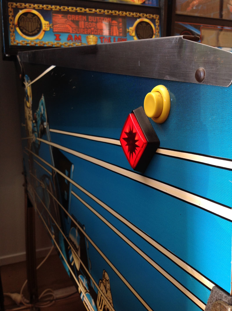
If you're a new Judge Dredd owner, you will probably be confused by a few connectors in the game. Judge Dredd has a few that simply do not connect to anything and sit unused. This is unnatural to most pinball restorers and we usually try to plug orphan connectors into a jack somewhere, but on Judge Dredd that's not the best solution!
The first oddity is J136 in the backbox. In some games I have seen it unplugged, yet in others it is connected. I initially plugged mine in after cleaning the machine up. However, plugging J136 in normally will cause weird lamp matrix issues such as making the Extra Ball and Super Game cabinet buttons flash when they shouldn't and making some playfield lights stay lit all of the time. This connector is a parallel connection to the start button lamp. There are a couple of threads on Pinside about it. The consensus is to leave this connector unplugged. 
Connector J136 in the backbox.
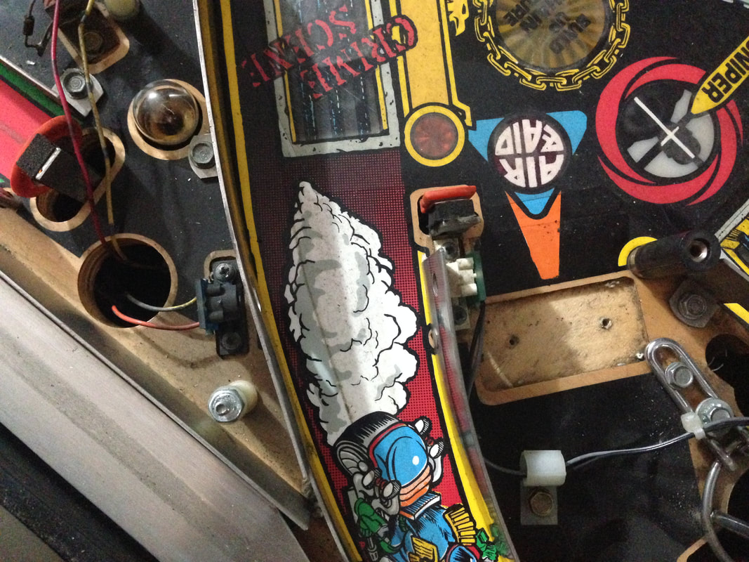
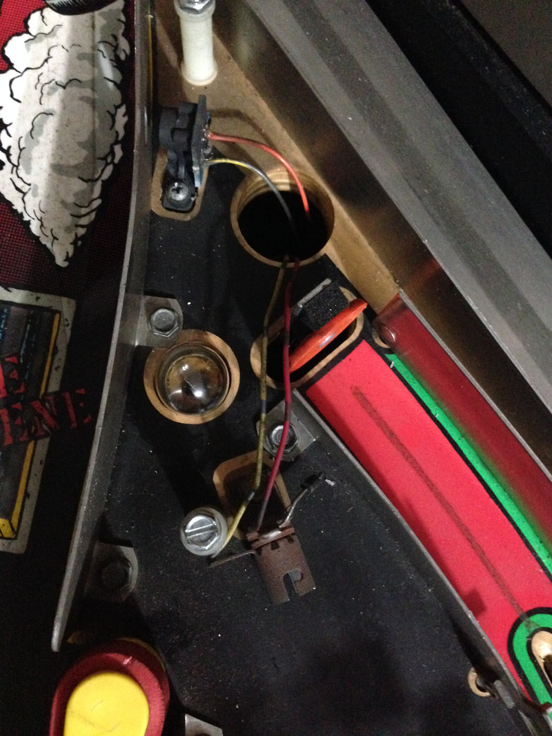
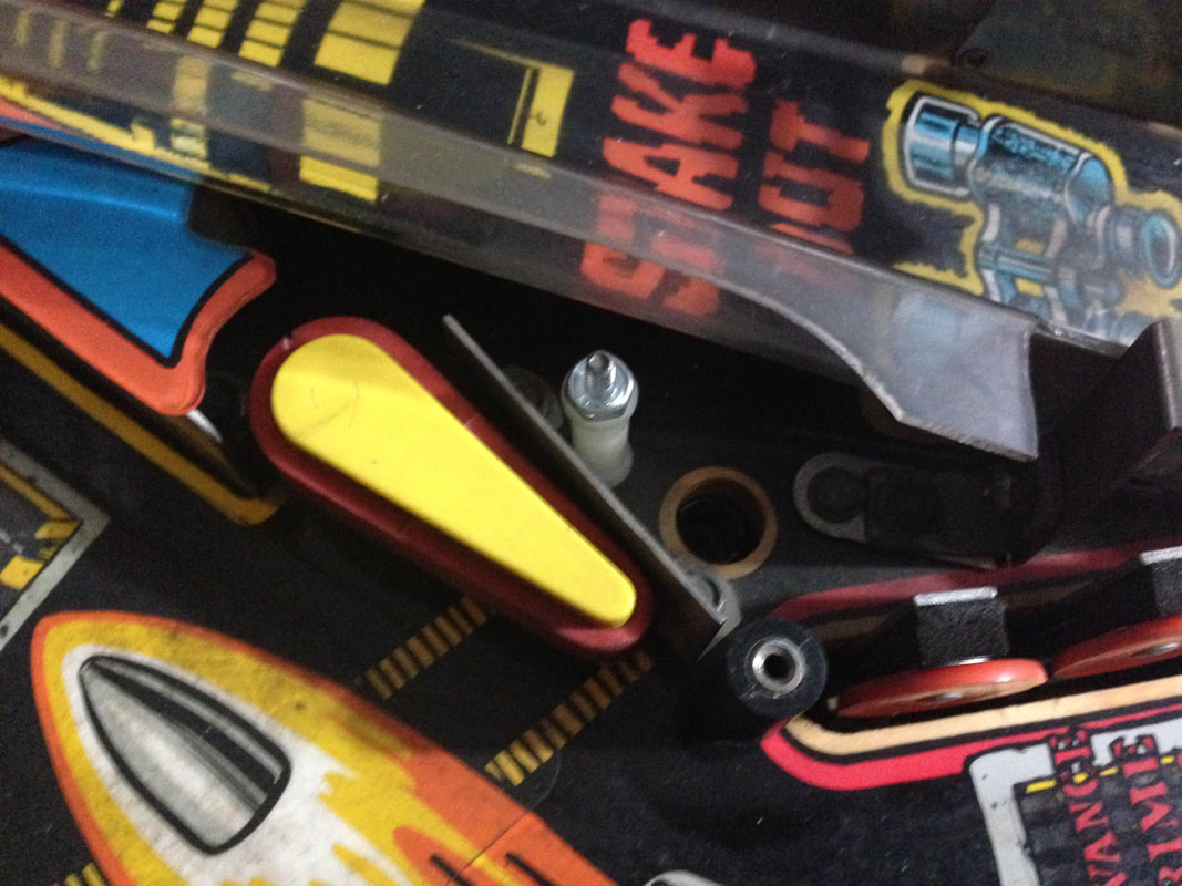
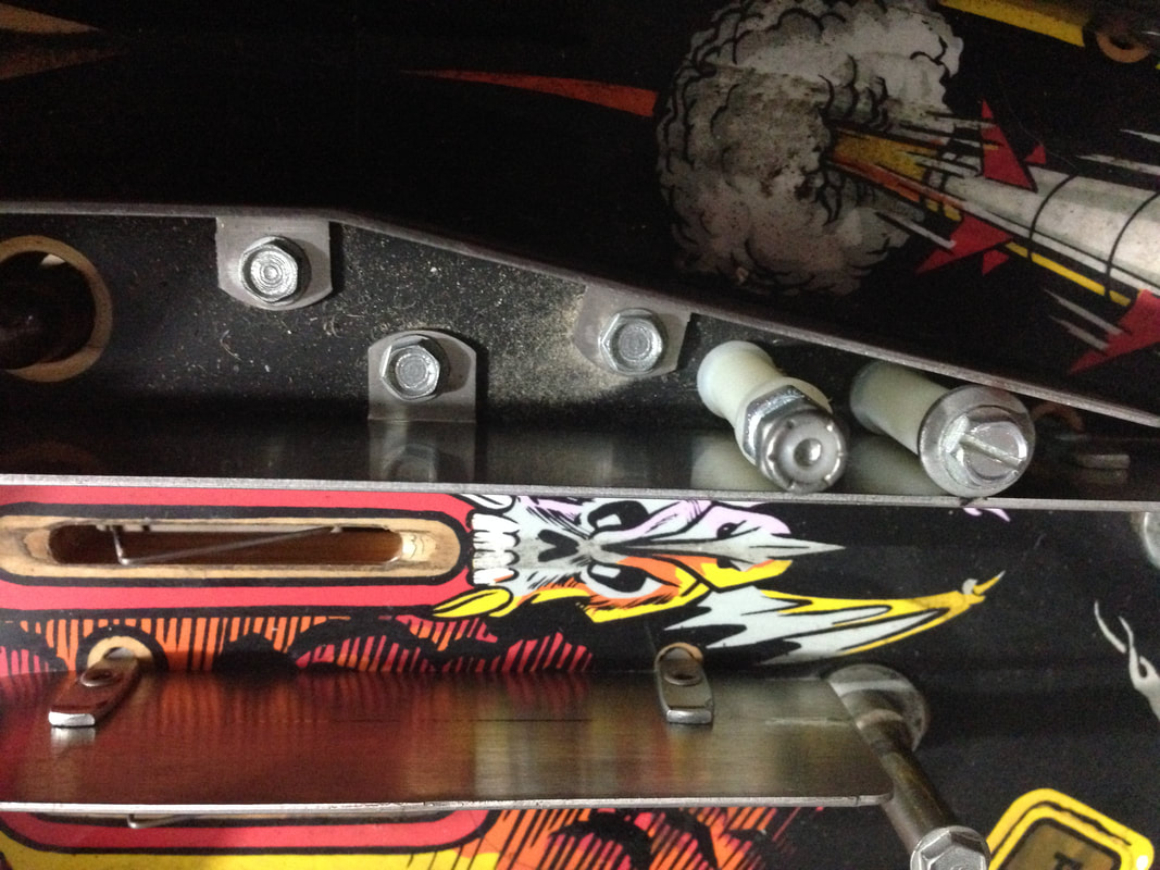
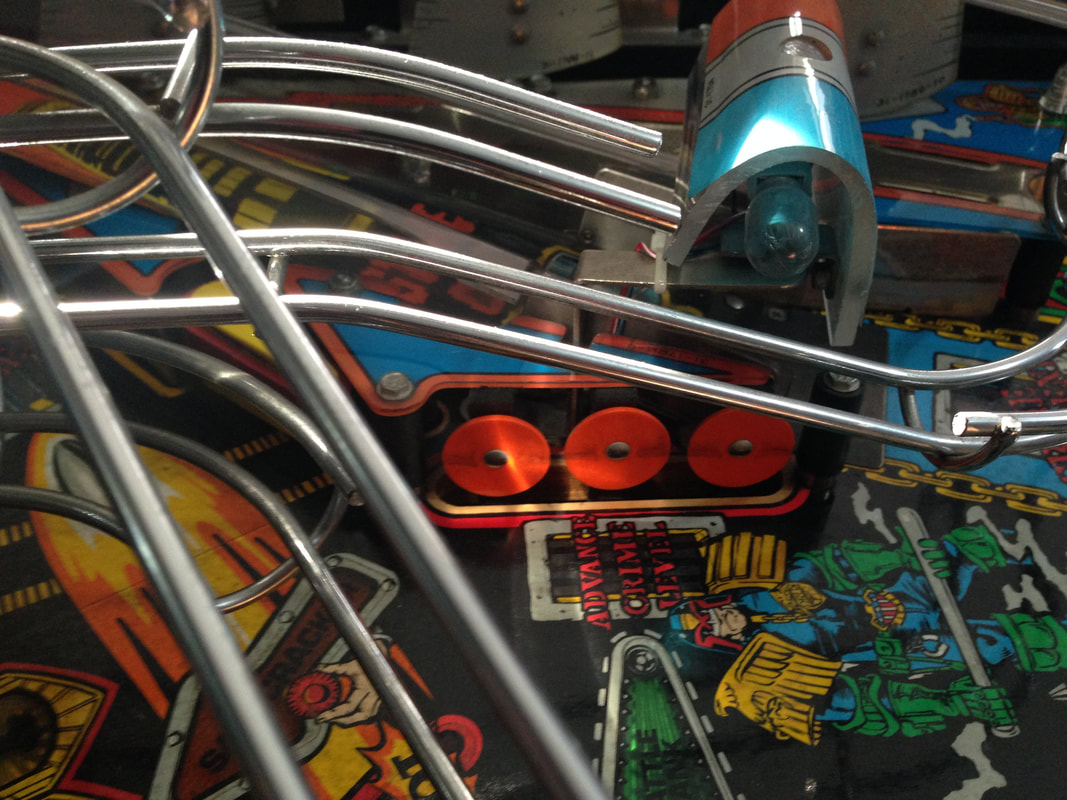
Next are the unused connectors under the playfield. The first is a connector with white and green wires that sits near the rear of the playfield. This one usually causes issues because it looks identical to a switch connector in this same area. The way to tell them apart is the number of wires connected to them. The connector with multiple wires connected to it should be left unplugged. There is an easy way to test whether the connectors are the right way around. Enter switch edge test and hit the bank of three standup targets (Advance Crime Scene). If the correct connector is plugged in, the targets will register properly. If the wrong one is plugged in, the tilt switch will register instead. 
Switch connector near the rear of the playfield.
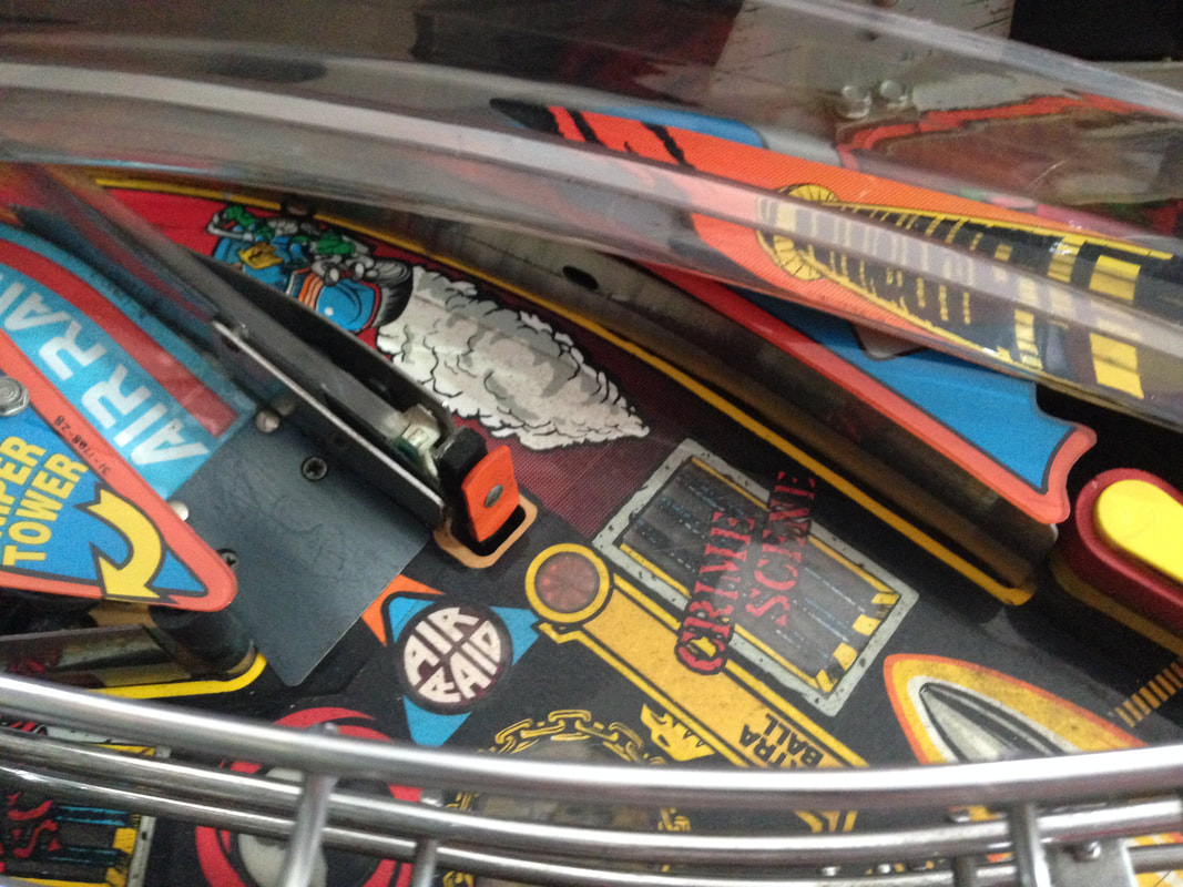
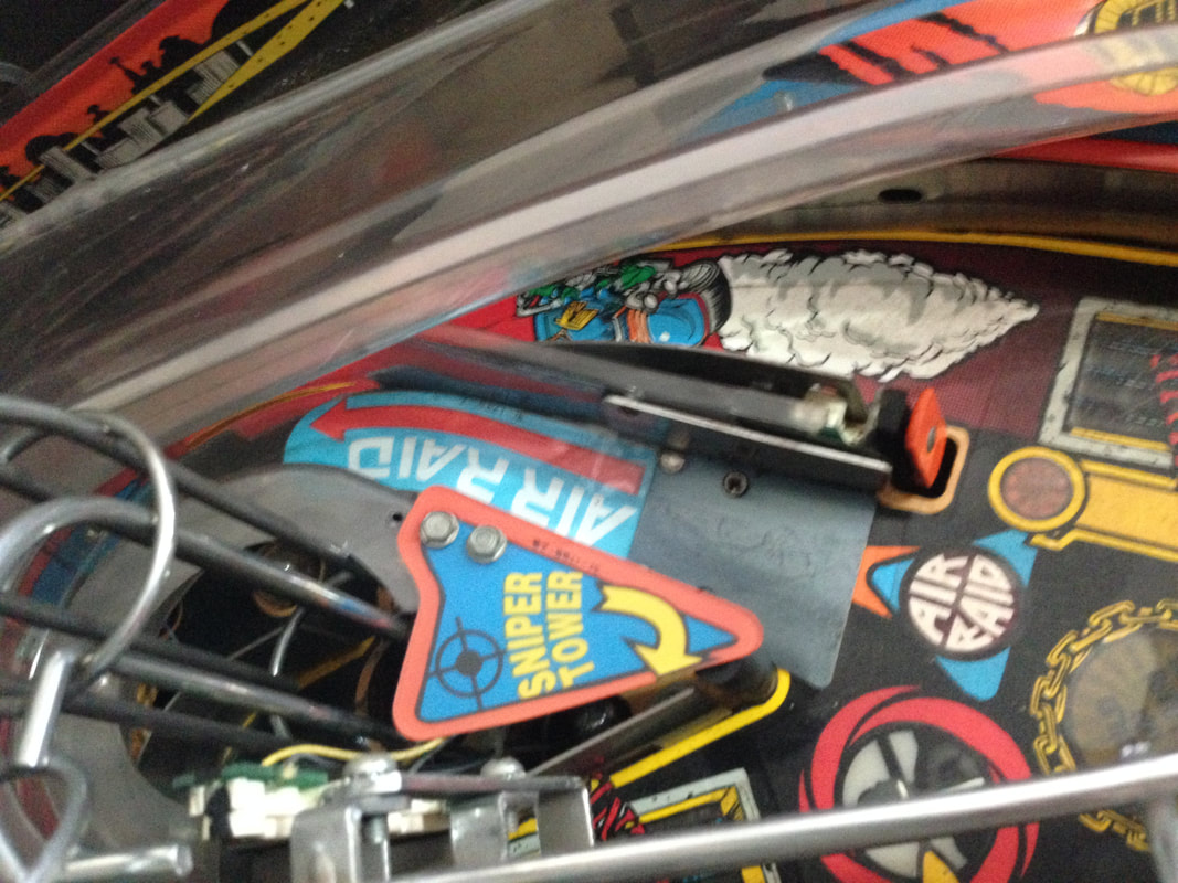
The last one is another Molex connector near the upper right flipper assembly. It has black, grey and orange wires going into it. Leave this one unplugged also. This one is a little less confusing because there isn't a male connector near it with similar wire colours. 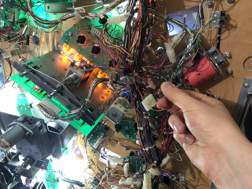
Female connector near the upper right flipper assembly.
Diverter coil not working
This issue started after I replaced some rubber rings on the playfield after I had pretty much finished restoring the game. I hadn't done anything to the diverter previously and it was working just fine up until this point. In test mode, the diverter wouldn't fire at all. I checked the basic stuff, including the wiring at the coil (all intact), voltage at the coil (present and in spec), and that the coil had not shorted out (it hadn't). Next, I started to suspect an upstream wiring issue, or a board issue. To narrow it down, I swapped in a working power driver board and tested the diverter - it worked fine.
So, that narrowed the problem down to a board issue. I inspected the original board and focused on transistor Q54, which controls the diverter. Surprise, surprise, the transistor was out of spec. I didn't think much of it, and replaced the components responsible for driving the coil (TIP102 transistor, 2N5401 transistor, and two resistors). However, when I booted the game up again, the diverter still didn't work. What the hell? I retested the components I installed with my multimeter, and they all appeared to be in spec. So why wasn't the coil firing? Time to do some further probing. This was one of my first opportunities to put my logic probe to the test. This probe was a $12 cheapie from eBay, but it was good enough for sorting basic logic issues such as this. WPC game manuals have a small section describing coil theory of operation. 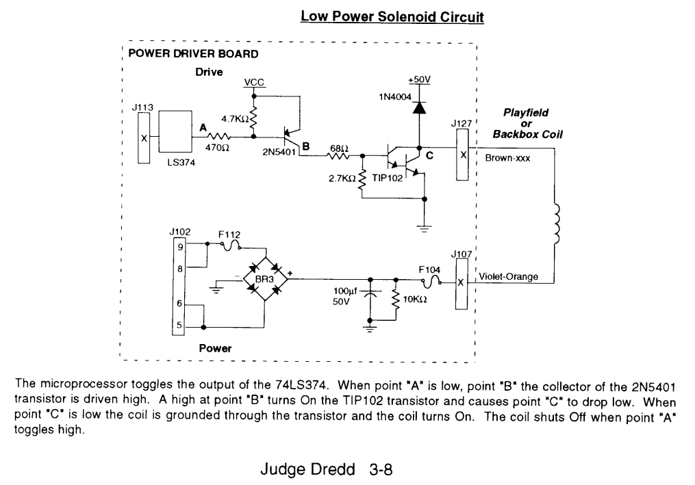
Low Power Solenoid circuit schematic diagram.
First port of call was to check the output of the 74LS374. In the case of the diverter coil, U4 is the controlling chip. The input is at pin 4, and the output is at pin 5. With the game in coil test and the diverter set to "repeat", I could see pin 5 flashing low every time the coil was supposed to be activated. All good there. Then, I checked the collector of the 2N5401 at Q53 (left leg when looking at the board installed in the game). This flashed high in sync with the coil test as well. So, the only component down the power train was the TIP102 transistor at Q54 which I had just replaced. All signs pointed to a problem with this transistor so I removed it from the board again to double check it hadn't failed. While doing this, I cleaned this area of the board and actually found the problem. The trace that connects Q54 to R92 (and then to ground) was severed. I didn't notice the first time because I was too quick in replacing the damaged components, and I didn't clean the board very thoroughly. Now the board was clean and I was looking at it, the broken trace was quite easy to see. It must have been blown out when the previous TIP102 failed. I jumpered this trace with some wire and all was good with the diverter coil again. Lesson learned: be slow and methodical when replacing parts as you might miss some obvious failures! 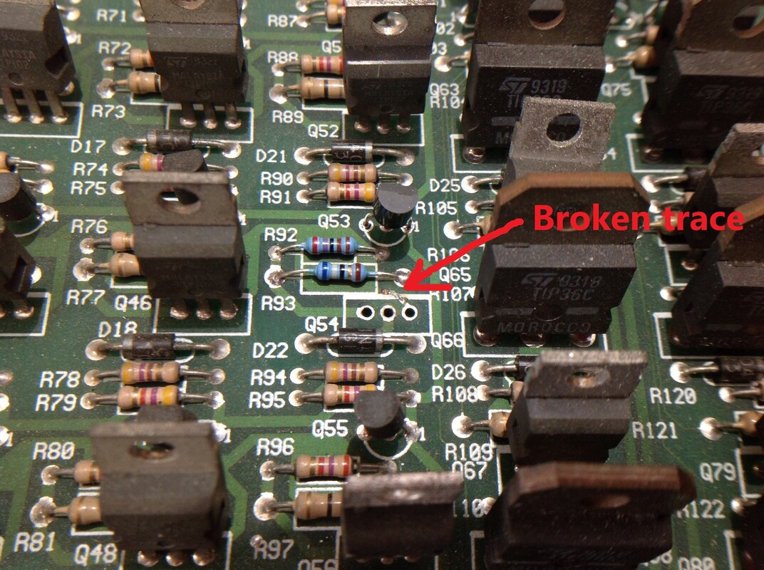
Broken trace at Q54.
Cabinet strengthening
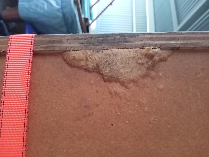
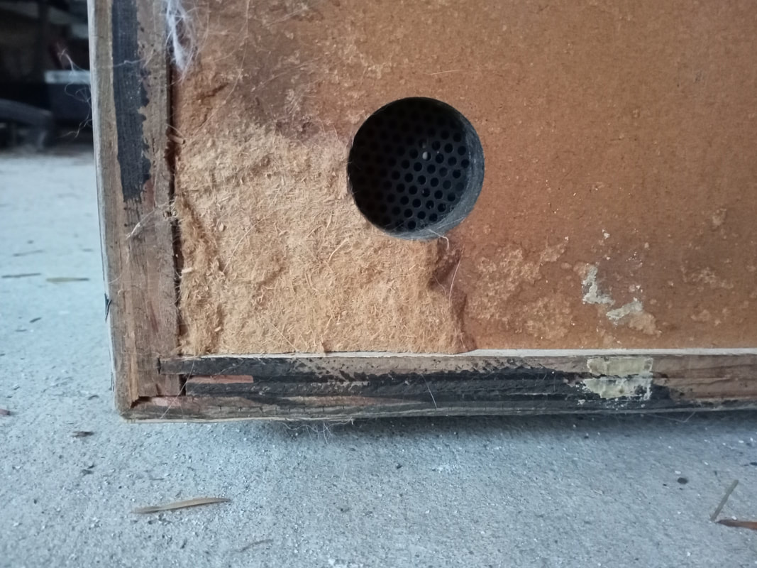
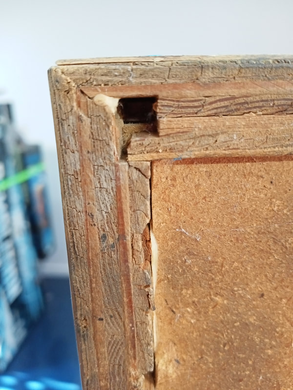
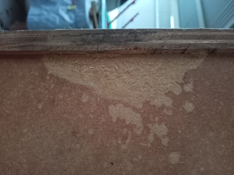
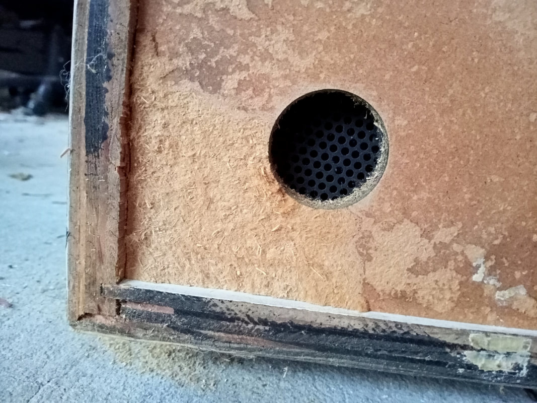
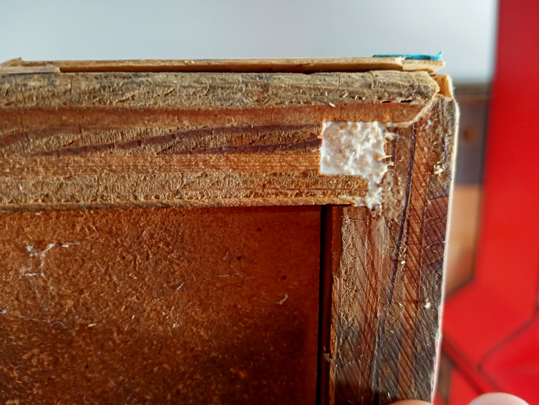
This was some additional work I did on the cabinet in 2021, when we moved house. Judge Dredd had been moved around and bashed around a fair bit since the original restoration, and one of the things I had not yet done was attend to some broken seams and cracks in the cabinet. The wood tends to spit a little at the joins after so many decades of abuse. Most cabinets need a little patchwork or glue to keep them as strong as possible. Plus, this cabinet had had some water affect it at some point, and the MDF in the corner and along one edge of the bottom of the cabinet had swelled up. MDF fibres were constantly flaking off so these areas needed to be repaired also.
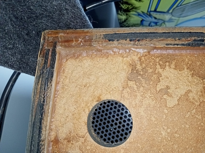
To deal with the areas of swelling, I sanded these down with an orbital sander until they were flush with the rest of the bottom panel and the fibres weren't flaking off so easily. Then, I applied a layer of basic wood glue such as Selley's Aquadhere to seal in the fibres. This locked things in nicely.
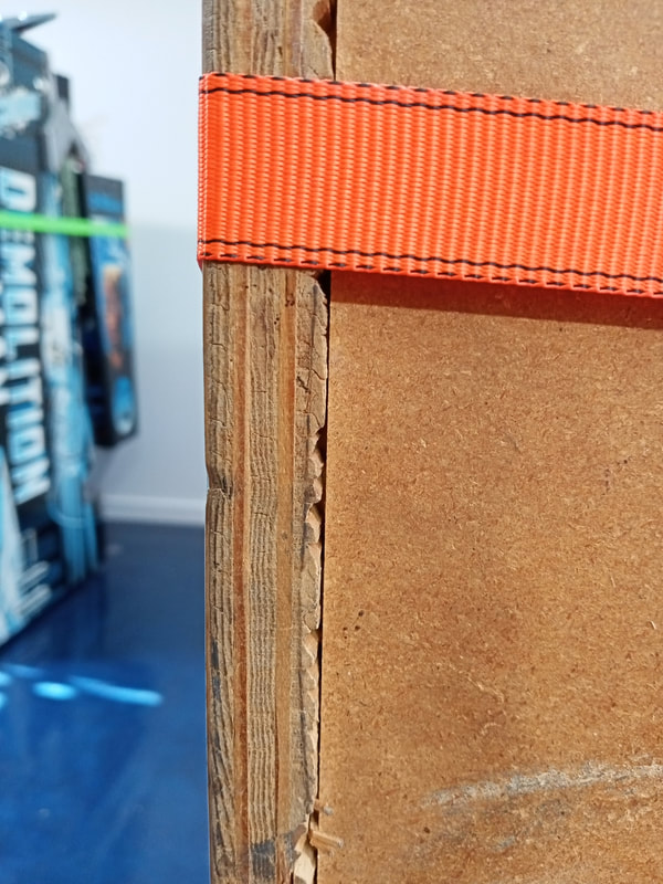
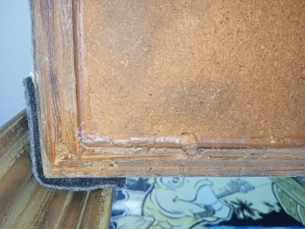
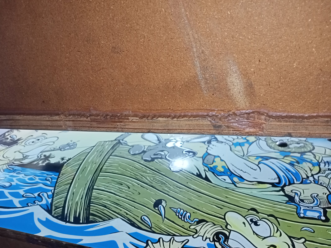
The splits in the sides of the cabinet were simple enough to fix with some liberal application of Selley's Liquid Nails Heavy Duty. I like the heavy duty stuff as the cabinet needs to be strong to withstand the shoves and tilts it usually sustains during play. The stronger the adhesive, the better! Squeeze it as far as possible into the split joins and pack it in with a craft stick as tightly as you can. You want to clear out any bubbles and air gaps to ensure the bond is strong. As for the large hole in the timber joint at the front corner, I simply filled this with a mixture of sawdust and wood glue, and packed it in tightly. I wasn't too concerned about the strength of this joint, and just wanted to fill it in. For these less important joints I use a basic wood glue such as Selley's Aquadhere. Then, some clamps around the cabinet to secure it in place as the glue sets. I use ratcheting straps (Bunnings) for this, as you can tighten them around the entire cabinet and clamp several joins at once. Leave the clamps in place for a day or two until the glue is set, and voila, all done! 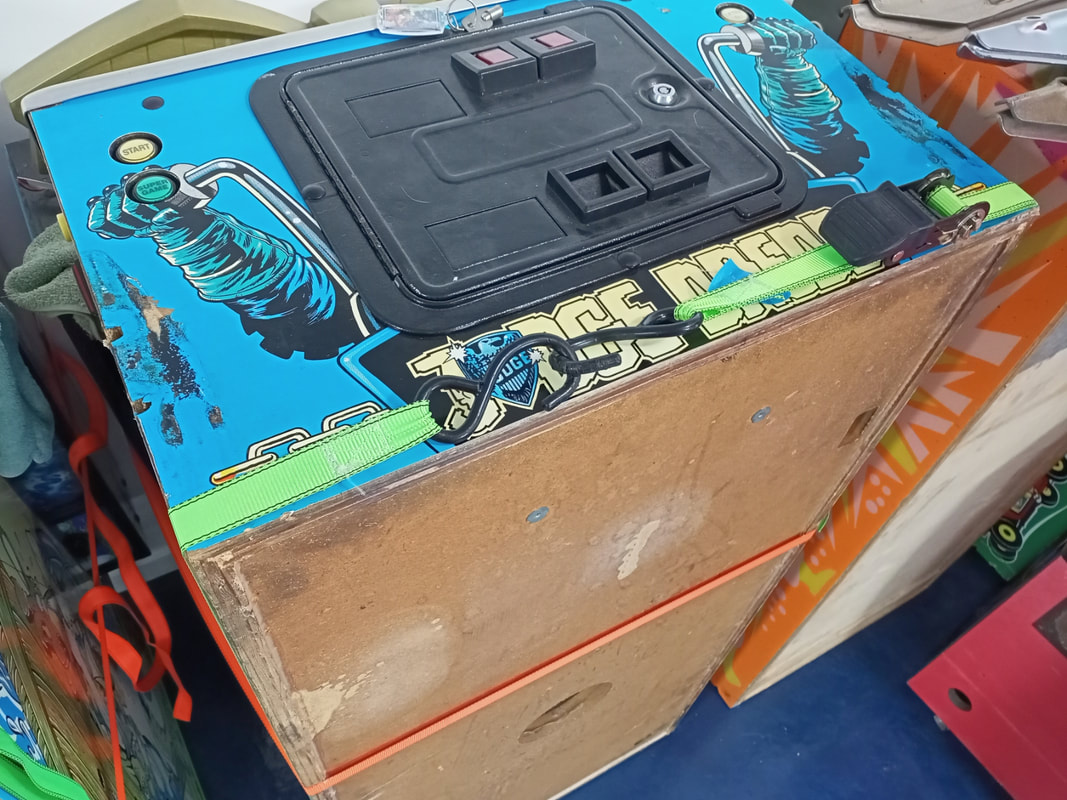
Clamping the cabinet for the glue to set.
Reassembly The main thing to remember when assembling Judge Dredd is to test the operation of the Deadworld before installing all of the ramps, plastics and wireforms that obstruct it. It is very hard to take it apart piecemeal so don't assume you'll be able to get to everything easily once it is installed on the playfield. I installed yellow Cliffy post sleeves throughout the game. The flipper bats on Judge Dredd are yellow, so I ordered some red Super-Bands which look good on them. For rubber, I used white rings, but can totally understand why some people prefer black. White works well with the brighter colours on the playfield, but black also fits the theme well. For LEDs, I installed colour-matched lamps in the inserts bought from Luke's Pinballs. Judge Dredd looks fantastic with some bright LEDs installed. However, I did not replace the incandescent globes used in the crime scene insert lamp boards. These are the ones that flash according to the crime scene level you reach in the game. These bulbs are flashed in sequence to create a strobe effect during gameplay, which makes it look like lights are flashing through the inserts, which have decals like barred windows. It's a really cool effect, but the LEDs don't reproduce it very well due to the fast speed at which they turn on. So it looks like incandescent globes do still have a place in pinball after all! The general illumination was replaced with white frosted LEDs, as were the lamps in the backbox. Judge Dredd has a huge number of GI lamps in the backbox - fifty! That's more than I have seen in other games. I made up a spreadsheet to make ordering and organising the LEDs simpler. Feel free to download it and use it if you wish.
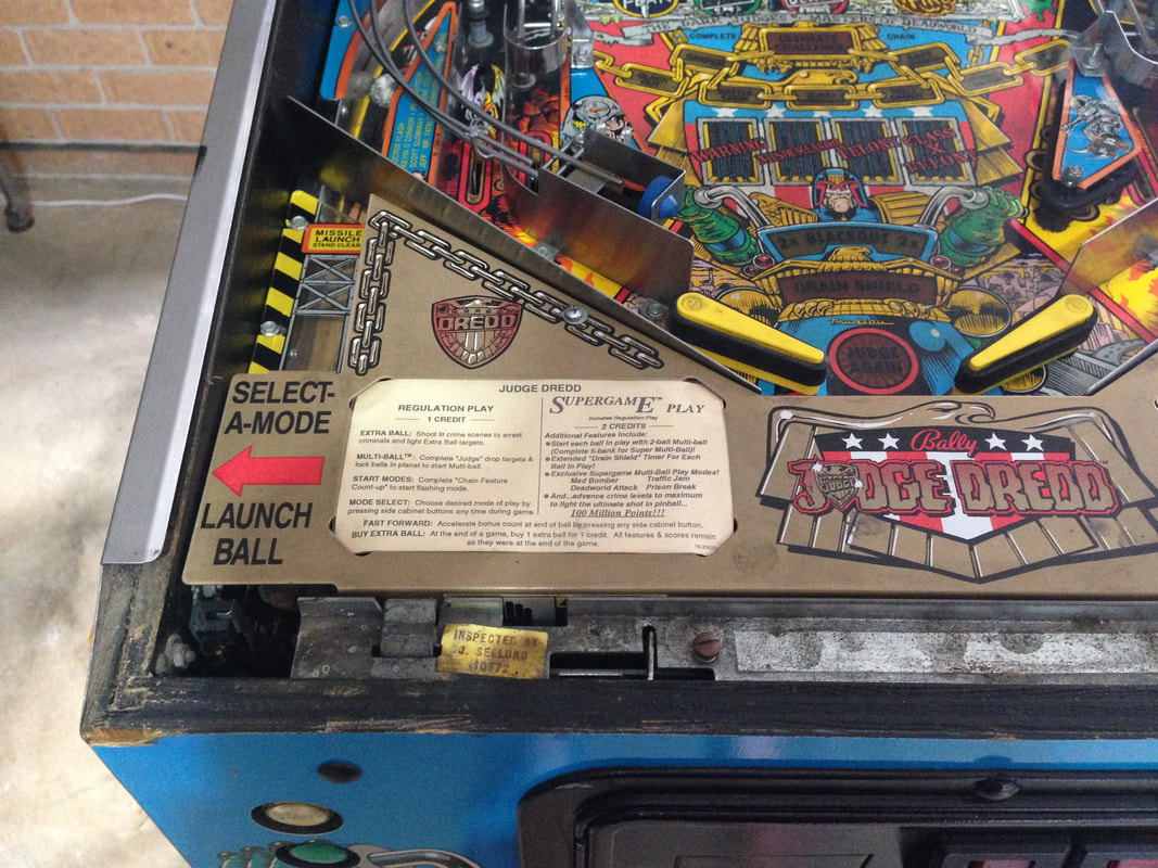
At the end of the restoration, I finished the playfield off by installing a Makrolon playfield protector overlay from Precision Gas Springs. This was necessary not only to protect the playfield from normal wear, but also to protect the touched-up areas from further damage. 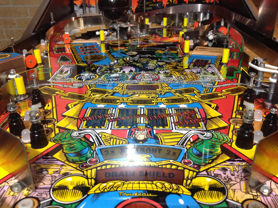 Playfield protector installed. And, of course, I downloaded some cool custom pricing and instruction cards. There are a few designs available however the ones I liked most were from Pinball Boy. These ones are orange and yellow and blend in perfectly with the playfield.  Conclusion Judge Dredd is an awesome game. Not only do you get a fully-featured widebody machine with lots of shots, you also get Supergame, which is like having a second game altogether. If you ever get bored of regular play, you can switch it up to Supergame, and vice versa. Supergame is actually a great way to practice multiball skills. It's one of the few multiball modes in a pinball game that you can literally start with the press of a button. The gameplay is smooth and there are lots of fun shots to make on the playfield. The Deadworld is a cool toy, too. Judge Dredd is definitely a multiball-centric game, though, so if you can't juggle balls, stay away! The music and sounds are also really catchy. In terms of the restoration, Judge Dredd was demanding. The Deadworld was a complex assembly to disassemble and clean, and it was very fiddly getting everything back together and working again. There were some interesting circuit board problems with the display and game resets, as well. Those were a good learning experience. I will keep Judge Dredd for a long time, I think. There's a lot of game for your buck in this cabinet (two games if you could Supergame!).
5 Comments
Simon
11/9/2019 08:44:52 pm
Excellent detail of the restoration process, extremely useful for anyone considering this on a Judge Dredd (it's a pity that I saw it AFTER I'd nearly completed mine haha)
Andy
23/2/2022 08:28:12 am
Great write up. I've had my JD here in England for almost 20 years. It doesn't need a full restoration, but it does need a proper clean up as it's stood unused for a good couple of years. Just fired it back up recently and got the bug back. Ordered a bunch of LED's for it (waiting for them to arrive), and cannot wait to get them fitted to see if it freshens it up. Thanks for giving me the motivation to get mine back up and running and the cleaning up has started.
Josh
4/7/2024 01:37:57 am
Great detail! Do you have the link or contact info for where you found that replacement gear for the Deadworld motor fix? Dredd is my first pinball machine and the gearbox is turning on the inside but not rotating the post/arm to move the world. I plan to take mine apart, swap lights and clean the unit/playfield as well so this will be immensely helpful.
Hi Josh Your comment will be posted after it is approved.
Leave a Reply. |
About
Here you will find logs of our pinball and arcade machine restorations, repairs, discussion about general pinball and arcade topics, as well as recounts of our random pinball adventures.
Check back regularly for updates! Blog updates
Archives
May 2024
Categories
All
Donate

Running this website is a hobby for me (just like pinball!). I like being able to show off my restoration work so everyone can learn from it and potentially fix their own machines. If you enjoy reading the site's content or it has been helpful to you, please consider donating to offset some of the website's operating costs. |
||||||||||||||||||||||||||||||||||||||


 RSS Feed